US10093254B2 - Bumper beam - Google Patents
Bumper beam Download PDFInfo
- Publication number
- US10093254B2 US10093254B2 US12/309,988 US30998807A US10093254B2 US 10093254 B2 US10093254 B2 US 10093254B2 US 30998807 A US30998807 A US 30998807A US 10093254 B2 US10093254 B2 US 10093254B2
- Authority
- US
- United States
- Prior art keywords
- bumper beam
- crown
- welds
- webs
- beam according
- Prior art date
- Legal status (The legal status is an assumption and is not a legal conclusion. Google has not performed a legal analysis and makes no representation as to the accuracy of the status listed.)
- Active, expires
Links
- 239000002184 metal Substances 0.000 claims description 3
- 230000000977 initiatory effect Effects 0.000 claims 2
- 229910000831 Steel Inorganic materials 0.000 description 3
- 239000010959 steel Substances 0.000 description 3
- 239000013256 coordination polymer Substances 0.000 description 2
- 238000000034 method Methods 0.000 description 2
- 238000012986 modification Methods 0.000 description 2
- 230000004048 modification Effects 0.000 description 2
- 229910000712 Boron steel Inorganic materials 0.000 description 1
- 230000007423 decrease Effects 0.000 description 1
- 239000003999 initiator Substances 0.000 description 1
- 238000005728 strengthening Methods 0.000 description 1
- 230000007704 transition Effects 0.000 description 1
- 230000003313 weakening effect Effects 0.000 description 1
- 238000003466 welding Methods 0.000 description 1
Images


Classifications
-
- B—PERFORMING OPERATIONS; TRANSPORTING
- B60—VEHICLES IN GENERAL
- B60R—VEHICLES, VEHICLE FITTINGS, OR VEHICLE PARTS, NOT OTHERWISE PROVIDED FOR
- B60R19/00—Wheel guards; Radiator guards, e.g. grilles; Obstruction removers; Fittings damping bouncing force in collisions
- B60R19/02—Bumpers, i.e. impact receiving or absorbing members for protecting vehicles or fending off blows from other vehicles or objects
- B60R19/18—Bumpers, i.e. impact receiving or absorbing members for protecting vehicles or fending off blows from other vehicles or objects characterised by the cross-section; Means within the bumper to absorb impact
-
- B—PERFORMING OPERATIONS; TRANSPORTING
- B60—VEHICLES IN GENERAL
- B60R—VEHICLES, VEHICLE FITTINGS, OR VEHICLE PARTS, NOT OTHERWISE PROVIDED FOR
- B60R19/00—Wheel guards; Radiator guards, e.g. grilles; Obstruction removers; Fittings damping bouncing force in collisions
- B60R19/02—Bumpers, i.e. impact receiving or absorbing members for protecting vehicles or fending off blows from other vehicles or objects
- B60R19/24—Arrangements for mounting bumpers on vehicles
-
- B—PERFORMING OPERATIONS; TRANSPORTING
- B60—VEHICLES IN GENERAL
- B60R—VEHICLES, VEHICLE FITTINGS, OR VEHICLE PARTS, NOT OTHERWISE PROVIDED FOR
- B60R19/00—Wheel guards; Radiator guards, e.g. grilles; Obstruction removers; Fittings damping bouncing force in collisions
- B60R19/02—Bumpers, i.e. impact receiving or absorbing members for protecting vehicles or fending off blows from other vehicles or objects
- B60R19/18—Bumpers, i.e. impact receiving or absorbing members for protecting vehicles or fending off blows from other vehicles or objects characterised by the cross-section; Means within the bumper to absorb impact
- B60R2019/1806—Structural beams therefor, e.g. shock-absorbing
- B60R2019/1813—Structural beams therefor, e.g. shock-absorbing made of metal
- B60R2019/1826—Structural beams therefor, e.g. shock-absorbing made of metal of high-tension steel
-
- B—PERFORMING OPERATIONS; TRANSPORTING
- B60—VEHICLES IN GENERAL
- B60R—VEHICLES, VEHICLE FITTINGS, OR VEHICLE PARTS, NOT OTHERWISE PROVIDED FOR
- B60R19/00—Wheel guards; Radiator guards, e.g. grilles; Obstruction removers; Fittings damping bouncing force in collisions
- B60R19/02—Bumpers, i.e. impact receiving or absorbing members for protecting vehicles or fending off blows from other vehicles or objects
- B60R19/18—Bumpers, i.e. impact receiving or absorbing members for protecting vehicles or fending off blows from other vehicles or objects characterised by the cross-section; Means within the bumper to absorb impact
- B60R2019/1893—Bumpers, i.e. impact receiving or absorbing members for protecting vehicles or fending off blows from other vehicles or objects characterised by the cross-section; Means within the bumper to absorb impact comprising a multiplicity of identical adjacent shock-absorbing means
Definitions
- the present invention relates to a bumper beam for a vehicle, which, at least in its attachment regions, is of generally U-shaped cross-section with the crown pointing outwards.
- WO 2006/002531 refers to a bumper beam with a hat-shaped profile.
- the web of the profile has holes for bolts and the beam is attached to the vehicle by bolts.
- a stiffening plate is disposed in the profile and runs along the profile in order to provide further support relative to the vehicle in the event of a collision.
- FIG. 1 is a view from above of the left half of a rear bumper beam according to the invention.
- FIG. 2 is a view from outside the vehicle of the bumper beam according to FIG. 1 .
- FIG. 3 is a view from inside the vehicle of the same bumper beam half as in FIG. 2 .
- FIG. 4 is a cross-section along the line 4 - 4 in FIG. 3 .
- FIGS. 5 and 6 correspond to FIG. 1 but depict two somewhat modified embodiments.
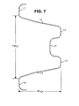
- FIG. 7 is a cross-section along the line 7 - 7 in FIG. 3 .
- FIGS. 1 and 2 depict the left half of a slightly curved rear bumper beam as seen from outside the vehicle and FIG. 3 depicts it as seen from inside the vehicle.
- the bumper beam is of generally U-shaped cross-section and made of sheetmetal, as illustrated in FIG. 4 . More specifically, the example depicted is a hat-shaped beam with a varying cross-section along its length. Its left half is usually a mirror image of the right one, although there may be small differences.
- the hat beam has a central flange comprising two outer planar portions 12 , 13 and a central groove 14 . On each side of the central flange, the hat beam has two webs 15 , 16 ending with two side flanges 17 , 18 .
- the crown of the hat beam i.e. the portions 12 - 16 , point outwards from the vehicle.
- the webs 15 , 16 thus constitute the sides of the crown.
- the shape of the crown may be more rounded than here depicted.
- the hat beam has an open cross section but alternatively it may have a sheet steel cover welded to it that makes a bumper beam with a partially or completely closed cross section.
- the bumper beam has a fastening portion or attachment region 20 at each end where the side flanges are planar and has fastening holes 21 , 22 , 23 for attachment by bolts to supporting elements of the vehicle, e.g. end plates on the vehicle's side rails.
- the web height of the bumper beam is greatest at the fastening portions and decreases gradually and gently towards the centre, where it is less than two-thirds of the maximum web height.
- the web height is greater than the greatest distance between the webs, whereas the web height at the centre of the beam is smaller than the greatest distance between the webs.
- the side flanges are bent towards the central flange, thereby strengthening the beam where it has a low profile.
- the central flange 12 - 14 widens asymmetrically towards the middle as a result of its planar portion 13 being broadened as seen from the fastening portions 20 .
- the bumper beam broadens by gentle curves asymmetrically downwards to be able to absorb impact forces which act low relative to the fastening. This configuration is suitable for vehicles which have brackets for the bumper beam positioned high.
- a sheet metal transverse bulkhead 25 which is adapted to the shape of the central flange 12 - 14 , is welded to the central flange's outer portions 12 , 13 by welds 26 , 27 and is also welded to the webs 15 , 16 by welds 28 , 29 close to the webs' connections to the side flanges.
- the bulkhead 25 extends down to the transition between the webs 15 , 16 and the side flanges 17 , 18 .
- the webs' intermediate portions have no welds but may alternatively be welded along their whole length or along the whole of one web, depending on the supplementary characteristics desired for the bumper beam.
- the bulkhead 25 is represented by a broken line in FIG. 1 .
- FIG. 4 depicts an alternative represented by a broken line 30 where the bulkhead does not abut against the webs except at the top and bottom and is at a distance from the webs in an intermediate portion 31 .
- FIG. 4 further illustrates that the profile height (PH AR ) of the beam is greater than the profile width (PW AR ) of the beam at the attachment regions ( 20 ) of the beam
- FIG. 7 illustrates that the profile height (PH CP ) of the beam is smaller than the profile width (PW CP ) of the beam at the longitudinal central portion of the beam.
- the bulkhead 25 being situated close to the region of the beam's greatest web height, provides the bumper beam with increased torsional rigidity and more stable deformation behaviour in collisions.
- the tendency to tilt when subjected to collision loading which is asymmetrical in the vertical direction is reduced.
- An asymmetrical beam tends to tilt when it absorbs a load which acts low, and in such cases the bulkhead considerably reduces the tendency to tilt. This also applies to a beam which is symmetrical in the vertical direction, particularly if the load acts in the vicinity of the fastening.
- the bulkhead increases the load level at which the bumper beam begins to deform plastically, particularly in the case of a collision acting on the fastening portion 20 .
- This load level may be modified by, for example, the bulkhead being as represented by the broken line 30 in FIG. 4 .
- This design according to the broken line 30 with an intermediate portion 31 where the bulkhead 25 is narrower than the smallest distance between the webs causes in this intermediate portion a bulkhead weakening which serves as a deformation initiator and results in more stable and more predictable deformation behaviour. It is also possible to make other modifications, symmetrical or asymmetrical, e.g. make holes in the bulkhead or provide its edges with notches in order to achieve similar results.
- the intermediate portion 31 of the bulkhead 30 is curved inwardly in a direction away from the web 15 .
- FIG. 1 depicts the bulkhead 25 running parallel with the longitudinal direction of the vehicle
- FIGS. 5 and 6 show the bulkhead 25 running somewhat obliquely to the longitudinal direction of the vehicle, but in all three cases the bulkhead 25 runs generally in the longitudinal direction of the vehicle. It is thus possible to adapt the bulkhead to achieve desired modifications of a bumper beam's deformation behaviour in collisions.
- a bulkhead according to the invention generally results in improved performance of a bumper beam of generally U-shaped cross-section without substantially increasing its weight.
- a bumper beam according to the invention may be formed by the press-hardening process whereby a hardenable sheet steel, usually boron steel, is hot-formed in a cooled tool and is directly hardened while still in the cooled tool. It is thus possible to achieve very high strength values. It is also possible to make the bumper beam by cold-forming of high-strength or ultra high-strength cold-forming steel. In either case the transverse bulkhead is attached preferably by welding, after the forming process.
Landscapes
- Engineering & Computer Science (AREA)
- Mechanical Engineering (AREA)
- Body Structure For Vehicles (AREA)
- Vibration Dampers (AREA)
- Fittings On The Vehicle Exterior For Carrying Loads, And Devices For Holding Or Mounting Articles (AREA)
- Moulds For Moulding Plastics Or The Like (AREA)
Abstract
A bumper beam for a vehicle has a hat beam profile, i.e. a generally U-shaped cross-section with the crown (12-16) pointing outwards. In each attachment region (20) it has a transverse bulkhead (25) fastened between the crown's sides (12, 13) and running generally in the longitudinal direction of the vehicle.
Description
The present invention relates to a bumper beam for a vehicle, which, at least in its attachment regions, is of generally U-shaped cross-section with the crown pointing outwards.
WO 2006/002531 refers to a bumper beam with a hat-shaped profile. The web of the profile has holes for bolts and the beam is attached to the vehicle by bolts. At each attachment region a stiffening plate is disposed in the profile and runs along the profile in order to provide further support relative to the vehicle in the event of a collision.
It is an object of the invention to provide a bumper beam of the kind indicated above, which is of high performance, exhibits stable deformation behaviour relative to its weight and has a reduced tendency to twist or tilt.
This is achieved by its having in each attachment region a transverse bulkhead which is fastened between the sides of the crown and runs generally in the vehicle's longitudinal direction.
The bumper beam has a fastening portion or attachment region 20 at each end where the side flanges are planar and has fastening holes 21, 22, 23 for attachment by bolts to supporting elements of the vehicle, e.g. end plates on the vehicle's side rails. The web height of the bumper beam is greatest at the fastening portions and decreases gradually and gently towards the centre, where it is less than two-thirds of the maximum web height. At the fastening portions the web height is greater than the greatest distance between the webs, whereas the web height at the centre of the beam is smaller than the greatest distance between the webs. Between the fastening portions, the side flanges are bent towards the central flange, thereby strengthening the beam where it has a low profile. The central flange 12-14 widens asymmetrically towards the middle as a result of its planar portion 13 being broadened as seen from the fastening portions 20. Between the fastening portions, the bumper beam broadens by gentle curves asymmetrically downwards to be able to absorb impact forces which act low relative to the fastening. This configuration is suitable for vehicles which have brackets for the bumper beam positioned high.
As best illustrated in FIG. 4 , there is in the fastening portion 20 between the two outermost fastening holes 21, 22 a sheet metal transverse bulkhead 25 which is adapted to the shape of the central flange 12-14, is welded to the central flange's outer portions 12, 13 by welds 26,27 and is also welded to the webs 15, 16 by welds 28,29 close to the webs' connections to the side flanges. The bulkhead 25 extends down to the transition between the webs 15, 16 and the side flanges 17, 18. The webs' intermediate portions have no welds but may alternatively be welded along their whole length or along the whole of one web, depending on the supplementary characteristics desired for the bumper beam. The bulkhead 25 is represented by a broken line in FIG. 1 . FIG. 4 depicts an alternative represented by a broken line 30 where the bulkhead does not abut against the webs except at the top and bottom and is at a distance from the webs in an intermediate portion 31.
The bulkhead 25, being situated close to the region of the beam's greatest web height, provides the bumper beam with increased torsional rigidity and more stable deformation behaviour in collisions. The tendency to tilt when subjected to collision loading which is asymmetrical in the vertical direction is reduced. An asymmetrical beam, as in the example depicted, tends to tilt when it absorbs a load which acts low, and in such cases the bulkhead considerably reduces the tendency to tilt. This also applies to a beam which is symmetrical in the vertical direction, particularly if the load acts in the vicinity of the fastening.
The bulkhead increases the load level at which the bumper beam begins to deform plastically, particularly in the case of a collision acting on the fastening portion 20. This load level may be modified by, for example, the bulkhead being as represented by the broken line 30 in FIG. 4 . This design according to the broken line 30 with an intermediate portion 31 where the bulkhead 25 is narrower than the smallest distance between the webs causes in this intermediate portion a bulkhead weakening which serves as a deformation initiator and results in more stable and more predictable deformation behaviour. It is also possible to make other modifications, symmetrical or asymmetrical, e.g. make holes in the bulkhead or provide its edges with notches in order to achieve similar results.
As also illustrated by FIG. 4 , the intermediate portion 31 of the bulkhead 30 is curved inwardly in a direction away from the web 15.
A bumper beam according to the invention may be formed by the press-hardening process whereby a hardenable sheet steel, usually boron steel, is hot-formed in a cooled tool and is directly hardened while still in the cooled tool. It is thus possible to achieve very high strength values. It is also possible to make the bumper beam by cold-forming of high-strength or ultra high-strength cold-forming steel. In either case the transverse bulkhead is attached preferably by welding, after the forming process.
Claims (20)
1. A bumper beam for a vehicle, which at least in attachment regions (20) of said bumper beam is of generally U-shaped cross-section with a crown (12-16) pointing outwards, said crown including a central flange and two webs extending from said central flange in a direction towards said vehicle, characterised in that the crown has a larger profile height than profile width at the attachment regions and a smaller profile height than profile width at a longitudinal central portion of said bumper beam such that the profile height of the bumper beam is larger at the attachment regions than at the longitudinal center, said bumper beam being oriented asymmetrically in a vertical direction relative to the longitudinal direction of extension of said bumper beam, and said bumper beam has in each said attachment region (20) a single transverse metal bulkhead (25) fastened between sides (12,13) of the crown and running generally in the longitudinal direction of the vehicle for reducing tilting of the bumper beam relative to the vehicle when the bumper beam is subjected to an impact force during a collision, each said transverse bulkhead being attached to said webs and arranged such that an intermediate portion of each said transverse bulkhead is curved inwardly away from at least one of said webs and does not directly abut against said at least one of said webs for initiating deformation of said transverse bulkhead during a collision.
2. A bumper beam according to claim 1 , characterised in that said bumper beam is of hat-shaped cross-section, the height of which is greatest in the attachment regions, and said bumper beam has planar side flanges (17, 18) with fastening holes (21-23) for bolts.
3. A bumper beam according to claim 2 , characterised in that, as seen along the beam, each transverse bulkhead (25) is situated between two fastening holes (21, 22).
4. A bumper beam according to claim 1 , characterised in that each said transverse bulkhead (25) is welded to the top of the crown and to the base of the crown by welds (26-29) but has no welds in an intermediate portion.
5. A bumper beam according to claim 4 , characterised in that said intermediate portion (31) with no welds is at a distance from the crown's sides (15, 16).
6. A bumper beam according to claim 2 , characterised in that each said transverse bulkhead (25) is welded to the top of the crown and to the base of the crown by welds (26-29) but has no welds in an intermediate portion.
7. A bumper beam according to claim 3 , characterised in that each said transverse bulkhead (25) is welded to the top of the crown and to the base of the crown by welds (26-29) but has no welds in an intermediate portion.
8. A bumper beam according to claim 2 , characterised in that each said transverse bulkhead (25) is welded to the top of the crown and to the base of the crown by welds (26,29) but has no welds in an intermediate portion, said intermediate portion (31) with no welds is at a distance from the crown's sides (15,16).
9. A bumper beam according to claim 3 , characterised in that each said transverse bulkhead (25) is welded to the top of the crown and to the base of the crown by welds (26, 29) but has no welds in an intermediate portion, said intermediate portion (31) with no welds is at a distance from the crown's sides (15, 16).
10. A bumper beam according to claim 1 , characterised in that said crown defines a central groove (14) extending longitudinally therewith.
11. A bumper beam according to claim 1 , wherein said bumper beam widens asymmetrically downwardly in a direction from said attachment regions towards the longitudinal center of the bumper beam for reducing tilting of the bumper beam relative to the vehicle when a lower portion of the bumper beam is subjected to an impact force during a collision.
12. A bumper beam according to claim 1 , characterised in that the height of said bumper beam is less than two thirds of the maximum height of the webs at the center of the bumper beam.
13. A bumper beam according to claim 10 , characterised in that the central groove is defined in the central flange.
14. A bumper beam according to claim 1 , characterised in that the bumper beam has side flanges (17, 18) extending from said webs (15, 16), said side flanges being bent towards said central flange between said attachment regions of said bumper beam.
15. A bumper beam for a vehicle, which at least in attachment regions (20) of said bumper beam is of generally U-shaped cross-section with a crown (12-16) pointing outwards, said crown including a central flange and two webs extending from said central flange in a direction towards said vehicle, characterised in that the crown has a larger profile height than profile width at the attachment regions and a smaller profile height than profile width at a longitudinal central portion of said bumper beam such that the profile height of the bumper beam is larger at the attachment regions than at the longitudinal center, said bumper beam has in each said attachment region (20) a single transverse metal bulkhead (25) fastened between sides (12,13) of the crown and running generally in the longitudinal direction of the vehicle, each said transverse bulkhead being attached to said webs and arranged such that an intermediate portion of each said transverse bulkhead is curved inwardly away from at least one of said webs and does not directly abut against said at least one of said webs for initiating deformation of said transverse bulkhead during a collision.
16. A bumper beam according to claim 15 , characterised in that said bumper beam is oriented asymmetrically in a vertical direction relative to the longitudinal direction of extension of said bumper beam.
17. A bumper beam according to claim 15 , characterised in that said bumper beam is oriented symmetrically in a vertical direction relative to the longitudinal direction of extension of said bumper beam.
18. A bumper beam according to claim 15 , characterised in that the height of said bumper beam is less than two thirds of the maximum height of the webs at the center of the bumper beam.
19. A bumper beam according to claim 15 , characterised in that said crown defines a central groove (14) extending longitudinally therewith.
20. A bumper beam according to claim 19 , characterised in that in that the central groove is defined in the central flange.
Applications Claiming Priority (4)
| Application Number | Priority Date | Filing Date | Title |
|---|---|---|---|
| SE0601679 | 2006-08-15 | ||
| SE0601679-4 | 2006-08-15 | ||
| SE0601679A SE530205C2 (en) | 2006-08-15 | 2006-08-15 | Bumper beam |
| PCT/SE2007/000704 WO2008020794A1 (en) | 2006-08-15 | 2007-08-01 | A bumper beam |
Publications (2)
| Publication Number | Publication Date |
|---|---|
| US20090295177A1 US20090295177A1 (en) | 2009-12-03 |
| US10093254B2 true US10093254B2 (en) | 2018-10-09 |
Family
ID=39082270
Family Applications (1)
| Application Number | Title | Priority Date | Filing Date |
|---|---|---|---|
| US12/309,988 Active 2027-12-17 US10093254B2 (en) | 2006-08-15 | 2007-08-01 | Bumper beam |
Country Status (7)
| Country | Link |
|---|---|
| US (1) | US10093254B2 (en) |
| EP (1) | EP2054272B1 (en) |
| JP (1) | JP5266222B2 (en) |
| KR (1) | KR101425917B1 (en) |
| AT (1) | ATE532674T1 (en) |
| SE (1) | SE530205C2 (en) |
| WO (1) | WO2008020794A1 (en) |
Cited By (2)
| Publication number | Priority date | Publication date | Assignee | Title |
|---|---|---|---|---|
| US20240246618A1 (en) * | 2018-08-07 | 2024-07-25 | Sti Holdings, Inc. | Stamped rear frame bolster |
| USD1087844S1 (en) | 2019-09-09 | 2025-08-12 | Sti Holdings, Inc. | Rear bolster |
Families Citing this family (7)
| Publication number | Priority date | Publication date | Assignee | Title |
|---|---|---|---|---|
| DE202008017596U1 (en) | 2008-09-05 | 2010-02-18 | Voestalpine Automotive Gmbh | Molded part made of sheet steel |
| KR101402022B1 (en) * | 2012-09-19 | 2014-05-30 | 주식회사 성우하이텍 | Bumper beam for vehicles |
| JP5987638B2 (en) * | 2012-10-31 | 2016-09-07 | マツダ株式会社 | Vehicle body structure |
| DE102013100720B4 (en) * | 2013-01-24 | 2014-11-27 | Benteler Automobiltechnik Gmbh | Cross member for a motor vehicle |
| SE537087C2 (en) * | 2013-03-13 | 2014-12-30 | Gestamp Hardtech Ab | Bumper beam |
| JP6575317B2 (en) * | 2015-11-17 | 2019-09-18 | トヨタ自動車株式会社 | Vehicle front structure |
| US11987192B2 (en) * | 2019-09-06 | 2024-05-21 | Kirchhoff Automotive Deutschland Gmbh | Bumper cross beam for a motor vehicle |
Citations (49)
| Publication number | Priority date | Publication date | Assignee | Title |
|---|---|---|---|---|
| US3790200A (en) * | 1972-03-24 | 1974-02-05 | Dura Corp | Vehicle bumper |
| DE2360525A1 (en) * | 1972-12-14 | 1974-06-20 | Ford Werke Ag | SHOCK ABSORBING BUMPER FOR MOTOR VEHICLES |
| US3851909A (en) * | 1972-03-24 | 1974-12-03 | Dura Corp | Vehicle bumper construction and method of making same |
| JPS5253336A (en) * | 1975-10-27 | 1977-04-28 | Toyo Tire & Rubber Co Ltd | Shock absorbing member |
| JPS5273433A (en) * | 1975-12-13 | 1977-06-20 | Toyo Tire & Rubber Co Ltd | Improved shock absorbing bumper |
| US4073528A (en) * | 1975-03-25 | 1978-02-14 | Daimler-Benz Aktiengesellschaft | Bumper for motor vehicles having a shock-absorbing profile |
| US4079975A (en) | 1975-09-20 | 1978-03-21 | Nissan Motor Company, Ltd. | Bumper construction |
| US4116480A (en) * | 1975-03-21 | 1978-09-26 | Itt Industries, Inc. | Automotive vehicle bumper |
| US4142753A (en) * | 1975-11-21 | 1979-03-06 | Daimler-Benz Aktiengesellschaft | Vehicle bumper |
| US4208069A (en) * | 1976-10-30 | 1980-06-17 | Daimler-Benz Aktiengesellschaft | Bumper-support body consisting of glass-fiber-reinforced synthetic plastic material |
| GB2084942A (en) * | 1980-07-30 | 1982-04-21 | Nissan Motor | Vehicle bumper guard molding |
| JPS598552A (en) * | 1982-07-07 | 1984-01-17 | Nissan Motor Co Ltd | Automobile bumper |
| JPS5948249A (en) * | 1982-09-13 | 1984-03-19 | Nissan Motor Co Ltd | Bumper reinforcing structure |
| FR2533181A1 (en) * | 1982-09-16 | 1984-03-23 | Fiat Auto Spa | AUTOMOTIVE BUMPER COMPRISING AN EXTERNAL PLASTIC ELEMENT WITH CURVED END |
| JPS59190059A (en) * | 1983-04-12 | 1984-10-27 | Nissan Motor Co Ltd | Rear-part chassis structure of car |
| US4925224A (en) * | 1989-03-06 | 1990-05-15 | Romeo-Rim, Inc. | Energy absorbing vehicle bumper |
| JPH05112190A (en) * | 1991-10-22 | 1993-05-07 | Daikyo Inc | Structure of bumper |
| EP0582524A1 (en) * | 1992-08-06 | 1994-02-09 | Compagnie Plastic Omnium | Bumper with a modular shockabsorber, in particular for a motor vehicle |
| JPH0769145A (en) * | 1993-09-06 | 1995-03-14 | Toyota Motor Corp | Car bumper |
| JPH07164983A (en) * | 1993-12-17 | 1995-06-27 | Toyota Motor Corp | Automotive bumper force |
| US5722708A (en) * | 1994-01-26 | 1998-03-03 | Plannja Hardtech Ab | Bumper structure |
| JP2001058519A (en) * | 1999-08-23 | 2001-03-06 | Honda Motor Co Ltd | Vehicle cooling air system |
| US6435579B1 (en) * | 1999-10-27 | 2002-08-20 | Patrick M. Glance | Bumper beam having double open sided channel members |
| US20020180222A1 (en) * | 2001-05-29 | 2002-12-05 | Janssen Aloysius Paulus Maria Helena Leonardus | Crash energy absorbing element |
| US6540276B2 (en) * | 2000-11-09 | 2003-04-01 | Aisin Seiki Kabushiki Kaisha | Bumper reinforcement structure |
| US6554345B2 (en) * | 1997-10-23 | 2003-04-29 | Ssab Hardtech Ab | Lightweight beam |
| WO2003080398A1 (en) | 2002-03-26 | 2003-10-02 | Valeo Thermique Moteur | Bumper beam with shock absorber for motor vehicle |
| US20030227182A1 (en) * | 2002-06-07 | 2003-12-11 | Om Corporation | Bumper reinforcement |
| US6779821B2 (en) * | 2000-10-13 | 2004-08-24 | Ssab Hardtech Ab | Bumper arrangement |
| JP2005067541A (en) * | 2003-08-27 | 2005-03-17 | Honda Motor Co Ltd | Bumper beam |
| US6902215B1 (en) * | 2004-03-08 | 2005-06-07 | Romeo-Rim, Inc. | Apparatus to attach a proximity sensor to an energy absorbing vehicle bumper |
| US6971691B1 (en) * | 2004-06-25 | 2005-12-06 | Shape Corporation | Vehicle bumper beam |
| WO2006002531A1 (en) | 2004-07-01 | 2006-01-12 | Magna International Inc. | Bumper beam for a motor vehicle |
| US6986536B1 (en) * | 2004-06-25 | 2006-01-17 | Shape Corporation | Vehicle bumper beam |
| US20060061111A1 (en) * | 2004-09-17 | 2006-03-23 | Shape Corporation | Bumper with face-mounted reinforcer |
| US7025396B2 (en) * | 2004-07-28 | 2006-04-11 | Honda Motor Co., Ltd. | Vehicle bumper structure |
| US7044515B2 (en) * | 2001-09-12 | 2006-05-16 | General Electric Company | Bumper beam with crush cans |
| JP2007246021A (en) * | 2006-03-17 | 2007-09-27 | Jfe Steel Kk | Shock absorbing member |
| US7316432B2 (en) * | 2003-12-08 | 2008-01-08 | Gestamp Hardtech Ab | Bumper beam and a vehicle with such a beam |
| US7357430B2 (en) * | 2003-06-06 | 2008-04-15 | Gestamp Hardtech Ab | Bumper beam for a vehicle |
| US20080315597A1 (en) * | 2007-06-22 | 2008-12-25 | Honda Motor Co., Ltd. | Bumper beam structure |
| US20090066095A1 (en) * | 2005-05-25 | 2009-03-12 | Lars Karlander | Bumper beam |
| US20090206617A1 (en) * | 2006-08-15 | 2009-08-20 | Hans Ahlin | bumper beam for a vehicle |
| US7611175B2 (en) * | 2004-02-25 | 2009-11-03 | Gestamp Hardtech Ab | Bumper beam for a vehicle |
| US20090273197A1 (en) * | 2006-11-09 | 2009-11-05 | Per Muskos | Bumper beam |
| US20090315344A1 (en) * | 2006-10-06 | 2009-12-24 | Faurecia Kunststoffe Automobilsysteme Gmbh | Support for the front unit of a motor vehicle and method for its production |
| US20100013249A1 (en) * | 2005-05-25 | 2010-01-21 | Lars Karlander | Bumper beam |
| US7703820B2 (en) * | 2005-04-29 | 2010-04-27 | Autotech Engineering, A.I.E. | Bumper reinforcing cross-member |
| US20100102578A1 (en) * | 2007-05-30 | 2010-04-29 | Johan Nilsson | Bumper Beam |
Family Cites Families (4)
| Publication number | Priority date | Publication date | Assignee | Title |
|---|---|---|---|---|
| JP2522835Y2 (en) * | 1990-07-27 | 1997-01-16 | スズキ株式会社 | Bumper mounting structure |
| JPH06247238A (en) * | 1993-03-01 | 1994-09-06 | Toyota Motor Corp | Bumper force structure |
| JP3911826B2 (en) * | 1998-03-10 | 2007-05-09 | マツダ株式会社 | Bumper structure |
| JP4360238B2 (en) * | 2004-03-19 | 2009-11-11 | マツダ株式会社 | Rear body structure of automobile |
-
2006
- 2006-08-15 SE SE0601679A patent/SE530205C2/en unknown
-
2007
- 2007-08-01 AT AT07769010T patent/ATE532674T1/en active
- 2007-08-01 US US12/309,988 patent/US10093254B2/en active Active
- 2007-08-01 WO PCT/SE2007/000704 patent/WO2008020794A1/en not_active Ceased
- 2007-08-01 EP EP07769010A patent/EP2054272B1/en active Active
- 2007-08-01 KR KR1020097004984A patent/KR101425917B1/en not_active Expired - Fee Related
- 2007-08-01 JP JP2009524577A patent/JP5266222B2/en active Active
Patent Citations (50)
| Publication number | Priority date | Publication date | Assignee | Title |
|---|---|---|---|---|
| US3790200A (en) * | 1972-03-24 | 1974-02-05 | Dura Corp | Vehicle bumper |
| US3851909A (en) * | 1972-03-24 | 1974-12-03 | Dura Corp | Vehicle bumper construction and method of making same |
| DE2360525A1 (en) * | 1972-12-14 | 1974-06-20 | Ford Werke Ag | SHOCK ABSORBING BUMPER FOR MOTOR VEHICLES |
| US4116480A (en) * | 1975-03-21 | 1978-09-26 | Itt Industries, Inc. | Automotive vehicle bumper |
| US4073528A (en) * | 1975-03-25 | 1978-02-14 | Daimler-Benz Aktiengesellschaft | Bumper for motor vehicles having a shock-absorbing profile |
| US4079975A (en) | 1975-09-20 | 1978-03-21 | Nissan Motor Company, Ltd. | Bumper construction |
| JPS5253336A (en) * | 1975-10-27 | 1977-04-28 | Toyo Tire & Rubber Co Ltd | Shock absorbing member |
| US4142753A (en) * | 1975-11-21 | 1979-03-06 | Daimler-Benz Aktiengesellschaft | Vehicle bumper |
| JPS5273433A (en) * | 1975-12-13 | 1977-06-20 | Toyo Tire & Rubber Co Ltd | Improved shock absorbing bumper |
| US4208069A (en) * | 1976-10-30 | 1980-06-17 | Daimler-Benz Aktiengesellschaft | Bumper-support body consisting of glass-fiber-reinforced synthetic plastic material |
| GB2084942A (en) * | 1980-07-30 | 1982-04-21 | Nissan Motor | Vehicle bumper guard molding |
| JPS598552A (en) * | 1982-07-07 | 1984-01-17 | Nissan Motor Co Ltd | Automobile bumper |
| JPS5948249A (en) * | 1982-09-13 | 1984-03-19 | Nissan Motor Co Ltd | Bumper reinforcing structure |
| FR2533181A1 (en) * | 1982-09-16 | 1984-03-23 | Fiat Auto Spa | AUTOMOTIVE BUMPER COMPRISING AN EXTERNAL PLASTIC ELEMENT WITH CURVED END |
| JPS59190059A (en) * | 1983-04-12 | 1984-10-27 | Nissan Motor Co Ltd | Rear-part chassis structure of car |
| US4925224A (en) * | 1989-03-06 | 1990-05-15 | Romeo-Rim, Inc. | Energy absorbing vehicle bumper |
| JPH05112190A (en) * | 1991-10-22 | 1993-05-07 | Daikyo Inc | Structure of bumper |
| EP0582524A1 (en) * | 1992-08-06 | 1994-02-09 | Compagnie Plastic Omnium | Bumper with a modular shockabsorber, in particular for a motor vehicle |
| JPH0769145A (en) * | 1993-09-06 | 1995-03-14 | Toyota Motor Corp | Car bumper |
| JPH07164983A (en) * | 1993-12-17 | 1995-06-27 | Toyota Motor Corp | Automotive bumper force |
| US5722708A (en) * | 1994-01-26 | 1998-03-03 | Plannja Hardtech Ab | Bumper structure |
| US6554345B2 (en) * | 1997-10-23 | 2003-04-29 | Ssab Hardtech Ab | Lightweight beam |
| JP2001058519A (en) * | 1999-08-23 | 2001-03-06 | Honda Motor Co Ltd | Vehicle cooling air system |
| US6435579B1 (en) * | 1999-10-27 | 2002-08-20 | Patrick M. Glance | Bumper beam having double open sided channel members |
| US6779821B2 (en) * | 2000-10-13 | 2004-08-24 | Ssab Hardtech Ab | Bumper arrangement |
| US6540276B2 (en) * | 2000-11-09 | 2003-04-01 | Aisin Seiki Kabushiki Kaisha | Bumper reinforcement structure |
| US20020180222A1 (en) * | 2001-05-29 | 2002-12-05 | Janssen Aloysius Paulus Maria Helena Leonardus | Crash energy absorbing element |
| US7044515B2 (en) * | 2001-09-12 | 2006-05-16 | General Electric Company | Bumper beam with crush cans |
| WO2003080398A1 (en) | 2002-03-26 | 2003-10-02 | Valeo Thermique Moteur | Bumper beam with shock absorber for motor vehicle |
| US20030227182A1 (en) * | 2002-06-07 | 2003-12-11 | Om Corporation | Bumper reinforcement |
| US7357430B2 (en) * | 2003-06-06 | 2008-04-15 | Gestamp Hardtech Ab | Bumper beam for a vehicle |
| JP2005067541A (en) * | 2003-08-27 | 2005-03-17 | Honda Motor Co Ltd | Bumper beam |
| US7316432B2 (en) * | 2003-12-08 | 2008-01-08 | Gestamp Hardtech Ab | Bumper beam and a vehicle with such a beam |
| US7611175B2 (en) * | 2004-02-25 | 2009-11-03 | Gestamp Hardtech Ab | Bumper beam for a vehicle |
| US6902215B1 (en) * | 2004-03-08 | 2005-06-07 | Romeo-Rim, Inc. | Apparatus to attach a proximity sensor to an energy absorbing vehicle bumper |
| US6971691B1 (en) * | 2004-06-25 | 2005-12-06 | Shape Corporation | Vehicle bumper beam |
| US6986536B1 (en) * | 2004-06-25 | 2006-01-17 | Shape Corporation | Vehicle bumper beam |
| WO2006002531A1 (en) | 2004-07-01 | 2006-01-12 | Magna International Inc. | Bumper beam for a motor vehicle |
| US7025396B2 (en) * | 2004-07-28 | 2006-04-11 | Honda Motor Co., Ltd. | Vehicle bumper structure |
| US20060061111A1 (en) * | 2004-09-17 | 2006-03-23 | Shape Corporation | Bumper with face-mounted reinforcer |
| US7703820B2 (en) * | 2005-04-29 | 2010-04-27 | Autotech Engineering, A.I.E. | Bumper reinforcing cross-member |
| US20090066095A1 (en) * | 2005-05-25 | 2009-03-12 | Lars Karlander | Bumper beam |
| US20100013249A1 (en) * | 2005-05-25 | 2010-01-21 | Lars Karlander | Bumper beam |
| JP2007246021A (en) * | 2006-03-17 | 2007-09-27 | Jfe Steel Kk | Shock absorbing member |
| US20090206617A1 (en) * | 2006-08-15 | 2009-08-20 | Hans Ahlin | bumper beam for a vehicle |
| US7954863B2 (en) * | 2006-08-15 | 2011-06-07 | Gestamp Hardtech Ab | Bumper beam for a vehicle |
| US20090315344A1 (en) * | 2006-10-06 | 2009-12-24 | Faurecia Kunststoffe Automobilsysteme Gmbh | Support for the front unit of a motor vehicle and method for its production |
| US20090273197A1 (en) * | 2006-11-09 | 2009-11-05 | Per Muskos | Bumper beam |
| US20100102578A1 (en) * | 2007-05-30 | 2010-04-29 | Johan Nilsson | Bumper Beam |
| US20080315597A1 (en) * | 2007-06-22 | 2008-12-25 | Honda Motor Co., Ltd. | Bumper beam structure |
Cited By (3)
| Publication number | Priority date | Publication date | Assignee | Title |
|---|---|---|---|---|
| US20240246618A1 (en) * | 2018-08-07 | 2024-07-25 | Sti Holdings, Inc. | Stamped rear frame bolster |
| US12291284B2 (en) * | 2018-08-07 | 2025-05-06 | Sti Holdings, Inc. | Stamped rear frame bolster |
| USD1087844S1 (en) | 2019-09-09 | 2025-08-12 | Sti Holdings, Inc. | Rear bolster |
Also Published As
| Publication number | Publication date |
|---|---|
| EP2054272B1 (en) | 2011-11-09 |
| JP5266222B2 (en) | 2013-08-21 |
| WO2008020794A1 (en) | 2008-02-21 |
| KR101425917B1 (en) | 2014-08-01 |
| EP2054272A4 (en) | 2009-11-04 |
| US20090295177A1 (en) | 2009-12-03 |
| SE530205C2 (en) | 2008-03-25 |
| SE0601679L (en) | 2008-02-16 |
| KR20090042958A (en) | 2009-05-04 |
| JP2010500230A (en) | 2010-01-07 |
| EP2054272A1 (en) | 2009-05-06 |
| ATE532674T1 (en) | 2011-11-15 |
Similar Documents
| Publication | Publication Date | Title |
|---|---|---|
| US10093254B2 (en) | Bumper beam | |
| JP4733702B2 (en) | Vehicle crash box | |
| JP6445687B2 (en) | Bumper reinforcement system for automobile | |
| US7794006B2 (en) | Bumper beam | |
| US8201872B2 (en) | One-piece shotgun with impact energy absorber | |
| US7357430B2 (en) | Bumper beam for a vehicle | |
| US7611175B2 (en) | Bumper beam for a vehicle | |
| US8544935B2 (en) | Door impact beam | |
| EP2150441B1 (en) | A bumper beam | |
| EP1888377B1 (en) | A bumper beam | |
| WO2018038210A1 (en) | Supporting structure for underrun protector | |
| JP6274382B1 (en) | Support structure for the underrun protector | |
| WO2007084044A1 (en) | A bumper beam | |
| EP2890601B1 (en) | Vehicle body front structure | |
| US20250229835A1 (en) | Front rail with crash tuning features |
Legal Events
| Date | Code | Title | Description |
|---|---|---|---|
| AS | Assignment |
Owner name: GESTAMP HARDTECH AB, SWEDEN Free format text: ASSIGNMENT OF ASSIGNORS INTEREST;ASSIGNORS:ASPLUND, MATTIAS;KARLANDER, LARS;SIGNING DATES FROM 20090126 TO 20090130;REEL/FRAME:022257/0780 |
|
| STCF | Information on status: patent grant |
Free format text: PATENTED CASE |
|
| MAFP | Maintenance fee payment |
Free format text: PAYMENT OF MAINTENANCE FEE, 4TH YEAR, LARGE ENTITY (ORIGINAL EVENT CODE: M1551); ENTITY STATUS OF PATENT OWNER: LARGE ENTITY Year of fee payment: 4 |