US10092992B2 - Polishing apparatus, polishing head, and retainer ring - Google Patents
Polishing apparatus, polishing head, and retainer ring Download PDFInfo
- Publication number
- US10092992B2 US10092992B2 US15/163,571 US201615163571A US10092992B2 US 10092992 B2 US10092992 B2 US 10092992B2 US 201615163571 A US201615163571 A US 201615163571A US 10092992 B2 US10092992 B2 US 10092992B2
- Authority
- US
- United States
- Prior art keywords
- ring
- retainer ring
- screw thread
- annular
- polishing
- Prior art date
- Legal status (The legal status is an assumption and is not a legal conclusion. Google has not performed a legal analysis and makes no representation as to the accuracy of the status listed.)
- Active, expires
Links
Images


Classifications
-
- B—PERFORMING OPERATIONS; TRANSPORTING
- B24—GRINDING; POLISHING
- B24B—MACHINES, DEVICES, OR PROCESSES FOR GRINDING OR POLISHING; DRESSING OR CONDITIONING OF ABRADING SURFACES; FEEDING OF GRINDING, POLISHING, OR LAPPING AGENTS
- B24B37/00—Lapping machines or devices; Accessories
- B24B37/27—Work carriers
- B24B37/30—Work carriers for single side lapping of plane surfaces
- B24B37/32—Retaining rings
-
- B—PERFORMING OPERATIONS; TRANSPORTING
- B24—GRINDING; POLISHING
- B24B—MACHINES, DEVICES, OR PROCESSES FOR GRINDING OR POLISHING; DRESSING OR CONDITIONING OF ABRADING SURFACES; FEEDING OF GRINDING, POLISHING, OR LAPPING AGENTS
- B24B37/00—Lapping machines or devices; Accessories
- B24B37/11—Lapping tools
-
- B—PERFORMING OPERATIONS; TRANSPORTING
- B24—GRINDING; POLISHING
- B24B—MACHINES, DEVICES, OR PROCESSES FOR GRINDING OR POLISHING; DRESSING OR CONDITIONING OF ABRADING SURFACES; FEEDING OF GRINDING, POLISHING, OR LAPPING AGENTS
- B24B37/00—Lapping machines or devices; Accessories
- B24B37/04—Lapping machines or devices; Accessories designed for working plane surfaces
- B24B37/07—Lapping machines or devices; Accessories designed for working plane surfaces characterised by the movement of the work or lapping tool
- B24B37/10—Lapping machines or devices; Accessories designed for working plane surfaces characterised by the movement of the work or lapping tool for single side lapping
- B24B37/105—Lapping machines or devices; Accessories designed for working plane surfaces characterised by the movement of the work or lapping tool for single side lapping the workpieces or work carriers being actively moved by a drive, e.g. in a combined rotary and translatory movement
- B24B37/107—Lapping machines or devices; Accessories designed for working plane surfaces characterised by the movement of the work or lapping tool for single side lapping the workpieces or work carriers being actively moved by a drive, e.g. in a combined rotary and translatory movement in a rotary movement only, about an axis being stationary during lapping
-
- B—PERFORMING OPERATIONS; TRANSPORTING
- B24—GRINDING; POLISHING
- B24B—MACHINES, DEVICES, OR PROCESSES FOR GRINDING OR POLISHING; DRESSING OR CONDITIONING OF ABRADING SURFACES; FEEDING OF GRINDING, POLISHING, OR LAPPING AGENTS
- B24B37/00—Lapping machines or devices; Accessories
- B24B37/11—Lapping tools
- B24B37/20—Lapping pads for working plane surfaces
-
- B—PERFORMING OPERATIONS; TRANSPORTING
- B24—GRINDING; POLISHING
- B24B—MACHINES, DEVICES, OR PROCESSES FOR GRINDING OR POLISHING; DRESSING OR CONDITIONING OF ABRADING SURFACES; FEEDING OF GRINDING, POLISHING, OR LAPPING AGENTS
- B24B37/00—Lapping machines or devices; Accessories
- B24B37/34—Accessories
-
- B—PERFORMING OPERATIONS; TRANSPORTING
- B24—GRINDING; POLISHING
- B24B—MACHINES, DEVICES, OR PROCESSES FOR GRINDING OR POLISHING; DRESSING OR CONDITIONING OF ABRADING SURFACES; FEEDING OF GRINDING, POLISHING, OR LAPPING AGENTS
- B24B47/00—Drives or gearings; Equipment therefor
- B24B47/10—Drives or gearings; Equipment therefor for rotating or reciprocating working-spindles carrying grinding wheels or workpieces
- B24B47/12—Drives or gearings; Equipment therefor for rotating or reciprocating working-spindles carrying grinding wheels or workpieces by mechanical gearing or electric power
-
- H10P52/00—
-
- H10P52/402—
-
- H10P54/00—
-
- H10P95/60—
Definitions
- seal rings which seal a gap between the drive ring and the retainer ring, are disposed inside and outside the first screw thread and the second screw thread, respectively.
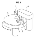
- the polishing head 1 is configured to be able to hold the wafer W on its lower surface by vacuum suction.
- the polishing head 1 and the polishing table 3 rotate in the same direction as indicated by arrows. In this state, the polishing head 1 presses the wafer W against the polishing surface 2 a of the polishing pad 2 .
- the polishing liquid is supplied from the polishing-liquid supply nozzle 5 onto the polishing pad 2 , so that the wafer W is polished by sliding contact with the polishing pad 2 in the presence of the polishing liquid.
Landscapes
- Engineering & Computer Science (AREA)
- Mechanical Engineering (AREA)
- Finish Polishing, Edge Sharpening, And Grinding By Specific Grinding Devices (AREA)
- Physics & Mathematics (AREA)
- Condensed Matter Physics & Semiconductors (AREA)
- General Physics & Mathematics (AREA)
- Manufacturing & Machinery (AREA)
- Computer Hardware Design (AREA)
- Microelectronics & Electronic Packaging (AREA)
- Power Engineering (AREA)
- Mechanical Treatment Of Semiconductor (AREA)
Abstract
A polishing apparatus which can allow easy replacement of a retainer ring and can allow the retainer ring to be secured to a drive ring without causing deformation of the retainer ring is disclosed. The polishing head includes a head body having a substrate contact surface, a drive ring coupled to the head body, and a retainer ring surrounding the substrate contact surface and coupled to the drive ring. A first screw thread is formed on the drive ring, a second screw thread, which engages with the first screw thread, is formed on the retainer ring. The second screw thread extends in a circumferential direction of the retainer ring.
Description
This document claims priorities to Japanese Patent Application No. 2015-105793 filed May 25, 2015, Japanese Patent Application No. 2016-007265 filed Jan. 18, 2016 and Japanese Patent Application No. 2016-096466 filed May 12, 2016, the entire contents of which are hereby incorporated by reference.
A CMP apparatus, which is a polishing apparatus, is configured to press a wafer against a polishing pad while supplying a polishing liquid (or slurry) onto the polishing pad to thereby polish the wafer. The polishing pad is supported on a polishing table, and is rotated together with the polishing table. The wafer is rotated by a polishing head, and is pressed against the rotating polishing pad by the polishing head. During polishing of the wafer, a lateral force acts on the wafer due to a friction between the wafer and the polishing pad. Thus, in order to prevent the wafer from coming off from the polishing head, the polishing head includes a retainer ring for retaining the wafer.
Since the retainer ring 301 is in sliding contact with the polishing pad during polishing of a wafer W, the retainer ring 301 is gradually worn away. Therefore, the retainer ring 301 is one of consumables which must be periodically replaced. However, in order to replace the retainer ring 301, it is necessary to remove the polishing head 300 from the polishing apparatus and to disassemble the polishing head 300, because the screws 307, securing the retainer ring 301, are disposed in the polishing head 300. Therefore, it takes considerable time to replace the retainer ring 301, resulting in an increase in a downtime of the polishing apparatus.
Further, when the retainer ring 301 is fastened by the plurality of screws 307, a stress in the retainer ring 301 may vary, thus possibly causing deformation of the retainer ring 301. The retainer ring 301 has not only a function to retain the wafer W during polishing, but also a function to control an amount of rebounding of the polishing pad to thereby control a polishing rate of a peripheral portion of the wafer W. If the retainer ring 301 is deformed, the polishing rate of the peripheral portion of the wafer W may vary.
According to embodiments, there are provided a polishing head and a polishing apparatus which can allow easy replacement of a retainer ring and can allow the retainer ring to be secured to a drive ring without causing deformation of the retainer ring. Further, according to an embodiment, there is provided a retainer ring capable of being easily mounted to and easily removed from the polishing head.
Embodiments, which will be described below, relate to a polishing apparatus for polishing a substrate, such as a wafer, and more particularly relate to a polishing apparatus for polishing a substrate on a polishing pad while pressing a retainer ring against the polishing pad around the substrate. Further, the below-described embodiments relate to a polishing head and a retainer ring for use in such a polishing apparatus.
In an embodiment, there is provided a polishing apparatus comprising: a polishing table for supporting a polishing pad; a polishing head for pressing a substrate against the polishing pad; and a head motor for rotating the polishing head, wherein the polishing head includes: a head body having a substrate contact surface; a drive ring coupled to the head body; and a retainer ring surrounding the substrate contact surface and coupled to the drive ring, a first screw thread is formed on the drive ring, a second screw thread, which engages with the first screw thread, is formed on the retainer ring, and the second screw thread extends in a circumferential direction of the retainer ring.
In an embodiment, the drive ring includes an annular drive ring body and an annular protrusion which protrudes downwardly from a lower surface of the annular drive ring body, an annular recess, which houses the annular protrusion therein, is formed in an upper surface of the retainer ring, and the first screw thread is formed on a side surface of the annular protrusion, and the second screw thread is formed on a side surface of the annular recess.
In an embodiment, the annular protrusion is constituted by at least a part of a screw ring secured to the annular drive ring body.
In an embodiment, a lower surface of the annular drive ring body is in contact with the upper surface of the retainer ring.
In an embodiment, the retainer ring includes an annular retainer ring body and a recess ring, the annular recess and the second screw thread being formed in the recess ring, and the recess ring has a higher strength than the annular retainer ring body.
In an embodiment, the retainer ring includes an annular retainer ring body and an annular protrusion which protrudes upwardly from an upper surface of the annular retainer ring body, an annular recess, which houses the annular protrusion therein, is formed in a lower surface of the drive ring, and the first screw thread is formed on a side surface of the annular recess, and the second screw thread is formed on a side surface of the annular protrusion.
In an embodiment, the annular protrusion is constituted by at least a part of a screw ring secured to the annular retainer ring body.
In an embodiment, an upper surface of the annular retainer ring body is in contact with a lower surface of the drive ring.
In an embodiment, seal rings, which seal a gap between the drive ring and the retainer ring, are disposed inside and outside the first screw thread and the second screw thread, respectively.
In an embodiment, a recess, with which a tightening tool for rotating the retainer ring about its own axis can engage, is formed in an outer circumferential surface of the retainer ring.
In an embodiment, the head motor has a lock function to lock a rotation of the polishing head.
In an embodiment, a direction in which the second screw thread is tightened is opposite to a direction in which the polishing head is rotated by the head motor when the polishing head is polishing the substrate.
In an embodiment, the polishing apparatus further comprises a locking structure for the first screw thread and the second screw thread.
In an embodiment, the locking structure is a lock ring which presses the retainer ring against the drive ring.
In an embodiment, the locking structure is a lock screw which restrains the rotation of the retainer ring relative to the drive ring.
In an embodiment, the locking structure includes a pin which is vertically movably supported by the drive ring, and the retainer ring has a hole into which a distal end of the pin can be inserted.
In an embodiment, the locking structure further includes a camshaft which is rotatably supported by the drive ring, and the camshaft has a cam portion and an exposed end, the cam portion being in engagement with the pin.
In an embodiment, the polishing apparatus further comprises a looseness detector for detecting a looseness of the second screw thread relative to the first screw thread.
In an embodiment, the looseness detector is a mark detector which detects a relative position of a first mark formed on the drive ring and a second mark formed on the retainer ring.
In an embodiment, the looseness detector is a load cell which is sandwiched between the drive ring and the retainer ring.
In an embodiment, there is provided a polishing head comprising: a head body having a substrate contact surface; a drive ring coupled to the head body; and a retainer ring surrounding the substrate contact surface and coupled to the drive ring, wherein a first screw thread is formed on the drive ring, a second screw thread, which engages with the first screw thread, is formed on the retainer ring, and the second screw thread extends in a circumferential direction of the retainer ring.
In an embodiment, there is provided a retainer ring for use in a polishing head which includes a head body having a substrate contact surface and a drive ring coupled to the head body, the retainer ring comprising: a second screw thread which can engage with a first screw thread formed on the drive ring, the second screw thread extending in a circumferential direction of the retainer ring.
The retainer ring is coupled to the drive ring by the engagement of the first screw thread and the second screw thread. Specifically, by rotating the entirety of the retainer ring, the second screw thread is engaged with the first screw thread, so that the retainer ring is secured to the drive ring. When the retainer ring is rotated in the opposite direction, the first screw thread and the second screw thread are disengaged, so that the retainer ring can be removed from the drive ring. In this manner, the retainer ring can be mounted and removed by simply rotating the retainer ring. Accordingly, it is not necessary to remove the polishing head from the polishing apparatus and it is also not necessary to disassemble the polishing head. Further, since the second screw thread extends in the circumferential direction of the retainer ring, a fastening force acting between the first screw thread and the second screw thread is uniform over the entire circumference of the retainer ring. Therefore, a stress generated in the retainer ring becomes uniform, and the retainer ring is not distorted.
Embodiments will be described in detail below with reference to the drawings. Identical or corresponding elements are denoted by the same reference numerals throughout the drawings, and their repetitive explanations will be omitted.
The polishing head 1 is configured to be able to hold the wafer W on its lower surface by vacuum suction. The polishing head 1 and the polishing table 3 rotate in the same direction as indicated by arrows. In this state, the polishing head 1 presses the wafer W against the polishing surface 2 a of the polishing pad 2. The polishing liquid is supplied from the polishing-liquid supply nozzle 5 onto the polishing pad 2, so that the wafer W is polished by sliding contact with the polishing pad 2 in the presence of the polishing liquid.
The polishing head 1 is coupled to a head shaft 11, which is vertically movable relative to a head arm 16 by a vertically moving mechanism 27. The vertical movement of the head shaft 11 causes a vertical movement of the entirety of the polishing head 1 relative to the head arm 16 and enables positioning of the polishing head 1. A rotary joint 25 is mounted to an upper end of the head shaft 11.
The vertically moving mechanism 27 for elevating and lowering the head shaft 11 and the polishing head 1 includes a bridge 28 for rotatably supporting the head shaft 11 through a bearing 26, a ball screw 32 mounted to the bridge 28, a support base 29 supported by pillars 30, and a servomotor 38 mounted to the support base 29. The support base 29 for supporting the servomotor 38 is secured to the head arm 16 through the pillars 30.
The ball screw 32 has a screw shaft 32 a coupled to the servomotor 38 and a nut 32 b which is in engagement with the screw shaft 32 a. The head shaft 11 is configured to move vertically together with the bridge 28. Therefore, when the servomotor 38 is set in motion, the bridge 28 moves vertically through the ball screw 32 to cause the head shaft 11 and the polishing head 1 to move vertically.
The head shaft 11 is further coupled to a rotary cylinder 12 through a key (not shown). This rotary cylinder 12 has a timing pulley 14 on its outer circumferential surface. A head motor 18 is secured to the head arm 16, and the timing pulley 14 is coupled through a timing belt 19 to a timing pulley 20 which is secured to the head motor 18. Therefore, when the head motor 18 is set in motion, the rotary cylinder 12 and the head shaft 11 are rotated together through the timing pulley 20, the timing belt 19, and the timing pulley 14, thus rotating the polishing head 1 about its own axis. The head motor 18, the timing pulley 20, the timing belt 19, and the timing pulley 14 constitute a polishing-head rotating mechanism for rotating the polishing head 1 about its own axis. The head arm 16 is supported by a head arm shaft 21, which is rotatably supported by a frame (not shown).
The polishing head 1 is configured to be able to hold a substrate, such as the wafer W, on its lower surface. The head arm 16 is configured to be able to pivot on the head arm shaft 21, so that the polishing head 1, holding the wafer W on its lower surface, is moved from a receiving position of the wafer W to a position above the polishing table 3 by the pivotal movement of the head arm 16. The polishing head 1 and the polishing table 3 are rotated individually, while the polishing liquid is supplied onto the polishing pad 2 from the polishing-liquid supply nozzle 5 disposed above the polishing table 3.
The polishing head 1 is lowered and then presses the wafer W against the polishing surface 2 a of the polishing pad 2. In this manner, the wafer W is placed in sliding contact with the polishing surface 2 a of the polishing pad 2 to polish a surface of the wafer W.
Next, the polishing head 1, which serves as the substrate holder, will be described. FIG. 3 is a cross-sectional view of the polishing head 1. The polishing head 1 is also called a top ring. As shown in FIG. 3 , the polishing head 1 includes a head body 10 for pressing the wafer W against the polishing surface 2 a, and a retainer ring 40 disposed so as to surround the wafer W. The head body 10 and the retainer ring 40 are configured to rotate together by the rotation of the head shaft 11. The retainer ring 40 is configured to be movable in the vertical direction independently of the head body 10.
The head body 10 has a circular flange 41, a spacer 42 mounted to a lower surface of the flange 41, and a carrier 43 mounted to a lower surface of the spacer 42. The flange 41 is coupled to the head shaft 11. The carrier 43 is coupled to the flange 41 through the spacer 42, so that the flange 41, the spacer 42, and the carrier 43 rotate together, and vertically move together. The flange 41, the spacer 42, and the carrier 43 are made of resin, such as engineering plastic (e.g., PEEK). The flange 41 may be made of metal, such as SUS, aluminum, or the like.
An elastic membrane 45, which is brought into contact with a back surface of the wafer W, is attached to a lower surface of the carrier 43. This elastic membrane 45 has a lower surface which serves as a substrate contact surface 45 a to be brought into contact with the wafer W. A pressure chamber 50 is formed between the carrier 43 and the elastic membrane 45. The pressure chamber 50 is coupled to a pressure regulator 65 via the rotary joint 25, so that pressurized fluid (e.g., pressurized air) is supplied from the pressure regulator 65 into the pressure chamber 50. The elastic membrane 45 is made of a highly strong and durable rubber material, such as ethylene propylene rubber (EPDM), polyurethane rubber, silicone rubber, or the like.
The pressure chamber 50 is further coupled to a ventilation mechanism (not shown), so that the pressure chamber 50 can be ventilated to the atmosphere. The pressure chamber 50 is further coupled to a vacuum pump. A plurality of through-holes (not shown) are formed in the substrate contact surface 45 a of the elastic membrane 45. When the vacuum pump creates a vacuum in the pressure chamber 50, the substrate contact surface 45 a can hold the wafer W by the vacuum suction. When the wafer W is polished, the pressurized fluid (e.g., pressurized air) is supplied into the pressure chamber 50. The wafer W is pressed against the polishing surface 2 a of the polishing pad 2 by the substrate contact surface 45 a of the elastic membrane 45.
The retainer ring 40 is disposed around the substrate contact surface 45 a of the elastic membrane 45. This retainer ring 40 is coupled to a drive ring 46 by a first screw thread 91 and a second screw thread 92. During polishing of the wafer W, the retainer ring 40 presses the polishing surface 2 a of the polishing pad 2, while surrounding the wafer W which is being pressed against the polishing pad 2 by the substrate contact surface 45 a. The wafer W is retained in the polishing head 1 by the retainer ring 40 so that the wafer W is prevented from coming off from the polishing head 1.
The drive ring 46 has an upper portion which is coupled to an annular retainer-ring pressing mechanism 60. This retainer-ring pressing mechanism 60 is configured to exert a uniform downward load on the entirety of the upper surface of the drive ring 46 to thereby press the entirety of the lower surface of the retainer ring 40 against the polishing surface 2 a of the polishing pad 2.
The retainer-ring pressing mechanism 60 includes an annular piston 61 secured to the upper portion of the drive ring 46, and an annular rolling diaphragm 62 coupled to an upper surface of the piston 61. The rolling diaphragm 62 forms a retainer-ring pressure chamber 63 therein. This retainer-ring pressure chamber 63 is coupled to the pressure regulator 65 via the rotary joint 25. When pressurized fluid (e.g., pressurized air) is supplied from the pressure regulator 65 into the retainer-ring pressure chamber 63, the rolling diaphragm 62 pushes down the piston 61, which in turn pushes down the entireties of the drive ring 46 and the retainer ring 40. In this manner, the retainer-ring pressing mechanism 60 presses the lower surface of the retainer ring 40 against the polishing surface 2 a of the polishing pad 2. Further, when the pressure regulator 65 or the vacuum pump (not shown) develops a negative pressure in the retainer-ring pressure chamber 63, the entireties of the retainer ring 40 and the drive ring 46 can be elevated. The retainer-ring pressure chamber 63 is further coupled to a ventilation mechanism (not shown), so that the retainer-ring pressure chamber 63 can be ventilated to the atmosphere.
The drive ring 46 is removably coupled to the retainer-ring pressing mechanism 60. More specifically, the piston 61 is made of a magnetic material such as metal, and a plurality of magnets (not shown) are disposed in the upper portion of the drive ring 46. These magnets magnetically attract the piston 61, so that the drive ring 46 is secured to the piston 61 by a magnetic force. Instead of using the magnetic force, the piston 61 and the drive ring 46 may be mechanically coupled to each other by a fastening member or the like. The drive ring 46 is coupled to a spherical bearing 85 through a coupling member 75. This spherical bearing 85 is disposed radially inwardly of the retainer ring 40.
Plural pairs of drive rollers 80, 80 are secured to the carrier 43. The drive rollers 80, 80 of each pair are arranged on both sides of each spoke 78, and are in rolling contact with both sides of each spoke 78. The rotation of the carrier 43 is transmitted to the spokes 78 through the drive rollers 80, 80, thereby rotating the drive ring 46 connected to the spokes 78. Therefore, the retainer ring 40, which is secured to the drive ring 46, rotates together with the head body 10.
As shown in FIG. 3 , the shaft portion 76 extends vertically in the spherical bearing 85. The shaft portion 76 of the coupling member 75 is supported by the spherical bearing 85, which is arranged at the center of the head body 10, such that the shaft portion 76 can move in the vertical direction. As shown in FIG. 4 , the carrier 43 has a plurality of radial grooves 43 a in which the spokes 78 are disposed, respectively. Each spoke 78 is movable freely in the vertical direction in each groove 43 a.
With these configurations, the drive ring 46 and the retainer ring 40, which are coupled to the coupling member 75, are vertically movable relative to the head body 10. Further, the drive ring 46 and the retainer ring 40 are tiltably supported by the spherical bearing 85. The retainer ring 40 is tillable and vertically movable relative to the substrate contact surface 45 a and the wafer W pressed by the substrate contact surface 45 a, and is capable of pressing the polishing pad 2 independently of the wafer W.
The first screw thread 91 and the second screw thread 92 are helical screw ridges that engage with each other. The first screw thread 91 is formed on the screw ring 94 of the drive ring 46, and the second screw thread 92 is formed on the retainer ring 40. The first screw thread 91 extends in a circumferential direction of the drive ring 46, and the second screw thread 92 extends in a circumferential direction of the retainer ring 40. The first screw thread 91 is formed over an entire circumference of the drive ring 46, and the second screw thread 92 is formed over an entire circumference of the retainer ring 40. When the retainer ring 40 is rotated, the first screw thread 91 and the second screw thread 92 are disengaged, so that the retainer ring 40 can be removed from the drive ring 46. The first screw thread 91 may not necessarily extend continuously. The first screw thread 91 may be partially discontinuous, so long as the first screw thread 91 is formed over the entire circumference of the drive ring 46. Similarly, the second screw thread 92 may not necessarily extend continuously, and thus the second screw thread 92 may be partially discontinuous, so long as the second screw thread 92 is formed over the entire circumference of the retainer ring 40.
In this embodiment, from the viewpoint of easiness of forming the first screw thread 91, the annular protrusion 95 is constituted by a part of the screw ring 94 which is a separate member from the annular drive ring body 47. The screw ring 94 may be secured to the lower surface 46 a of the annular drive ring body 47 such that the annular protrusion 95 is constituted by the entirety of the screw ring 94. In order to more firmly secure the screw ring 94 to the annular drive ring body 47, the screw ring 94 may be glued to the annular drive ring body 47, and be then secured by the mounting screws 90. The screw ring 94 and the annular drive ring body 47 may be integrally made of the same material to form the drive ring 46.
The annular protrusion 95 extends over the entire circumference of the annular drive ring body 47, and is concentric with the annular drive ring body 47 and the retainer ring 40. The first screw thread 91 is formed on an inner side surface of the annular protrusion 95. An annular recess 97, which houses the annular protrusion 95 therein, is formed in the upper surface of the retainer ring 40. The second screw thread 92 is formed on an inner side surface of the annular recess 97. The annular recess 97 extends over the entire circumference of the retainer ring 40, and is concentric with the retainer ring 40. In this embodiment, the first screw thread 91 is a female thread, and the second screw thread 92 is a male thread.
By rotating the entirety of the retainer ring 40 about its own axis, the second screw thread 92 is engaged with the first screw thread 91 as shown in FIG. 5 , so that the retainer ring 40 can be coupled (i.e., secured) to the drive ring 46. Further, by rotating the entirety of the retainer ring 40 about its own axis in the opposite direction, the first screw thread 91 and the second screw thread 92 are disengaged, so that the retainer ring 40 can be removed from the drive ring 46 as shown in FIG. 6 .
In this manner, the retainer ring 40 can be attached and removed by simply rotating the retainer ring 40. Therefore, it is not necessary to remove the polishing head 1 from the polishing apparatus, and it is also not necessary to disassemble the polishing head 1. Further, a fastening force acting between the first screw thread 91 and the second screw thread 92 is uniform over the entire circumference of the retainer ring 40, because the first screw thread 91 and the second screw thread 92 continuously (or discontinuously) extend over the entire circumference of the retainer ring 40. Therefore, a stress generated in the retainer ring 40 also becomes uniform, and as a result, the retainer ring 40 is not distorted.
When the polishing head 1 is rotating, a torque acts on the retainer ring 40 due to a friction between the retainer ring 40 and the polishing pad 2. In order to prevent the first screw thread 91 and the second screw thread 92 from being loosened during polishing of the wafer W, a direction in which the second screw thread 92 is tightened may be opposite to a direction in which the polishing head 1 (and the retainer ring 40) is rotated by the head motor 18 (see FIG. 2 ) when the wafer W is polished. It is noted that this anti-looseness mechanism is not necessary if a sufficient fastening force can be achieved by the first screw thread 91 and the second screw thread 92.
As shown in FIG. 5 , the retainer ring 40 is coupled to the drive ring 46, with the upper surface 40 a of the retainer ring 40 being pressed against the lower surface 46 a of the annular drive ring body 47 of the drive ring 46 by the fastening force of the first screw thread 91 and the second screw thread 92. The lower surface 46 a of the annular drive ring body 47 is in contact with the upper surface 40 a of the retainer ring 40. The first screw thread 91 and the second screw thread 92 are completely enclosed by the drive ring 46 and the retainer ring 40 such that these screw threads 91, 92 are not exposed to the exterior. Therefore, during polishing of the wafer W, the polishing liquid (or slurry) does not reach the first screw thread 91 and the second screw thread 92, so that a smooth removal of the retainer ring 40 can be ensured.
In order to more reliably prevent the entry of the polishing liquid (slurry), as shown in FIG. 7 , seal rings 100A, 100B, such as O-rings, may preferably be provided between the drive ring 46 and the retainer ring 40. In an embodiment shown in FIG. 7 , the inner seal ring 100A, which is an O-ring, is disposed inside the first screw thread 91 and the second screw thread 92. The outer seal ring 100B, which is an O-ring, is disposed outside the first screw thread 91 and the second screw thread 92. These two seal rings 100A, 100B seal a gap between the drive ring 46 and the retainer ring 40, more specifically a gap between the lower surface 46 a of the annular drive ring body 47 and the upper surface 40 a of the retainer ring 40.
In an embodiment shown in FIG. 8 , the inner seal ring 100A has an inverted U-shaped cross section. An inner circumferential edge of the inner seal ring 100A is connected to the carrier 43 of the head body 10, and an outer circumferential edge of the inner seal ring 100A is sandwiched between the drive ring 46 and the retainer ring 40, more specifically between the lower surface 46 a of the annular drive ring body 47 and the upper surface 40 a of the retainer ring 40. The inverted U-shaped inner seal ring 100A has a shape that can prevent the slurry from entering a space between the elastic membrane (or the membrane) 45 and the retainer ring 40, and does not obstruct the vertical movement of the retainer ring 40. The inner seal ring 100A shown in FIG. 8 may be integral with the elastic membrane 45.
According to both the embodiment shown in FIG. 5 and FIG. 6 and the embodiment shown in FIG. 9 and FIG. 10 , the retainer ring 40 can be secured to the drive ring 46 by the engagement of the first screw thread 91 and the second screw thread 92. Because there is a difference in position where the fastening force is generated between these embodiments, it is preferable to select proper one of the embodiments according to polishing conditions.
The annular retainer ring body 48 is made of resin, while the recess ring 49 is made of a material having a higher strength than the annular retainer ring body 48, such as metal, ceramic, carbon, or PEEK. From the viewpoint of cost, a stainless steel having a high corrosion-resistance is preferably used. In a case where an eddy current sensor is used for measuring a film thickness of the wafer W, the recess ring 49 is preferably made of a non-metal material having a high strength, such as ceramic. As shown in FIG. 13 , the recess ring 49 may be applied to the embodiment shown in FIG. 9 and FIG. 10 .
The annular protrusion 95 extends over the entire circumference of the annular retainer ring body 48, and is concentric with the annular retainer ring body 48. Annular recess 97, which houses the annular protrusion 95 therein, is formed in the lower surface 46 a of the drive ring 46. The first screw thread 91 is formed on an inner side surface of the annular recess 97. The second screw thread 92 is formed on an inner side surface of the annular protrusion 95. The annular recess 97 extends over the entire circumference of the drive ring 46, and is concentric with the drive ring 46. In this embodiment, the first screw thread 91 is a male thread, and the second screw thread 92 is a female thread. The first screw thread 91 may be formed on an outer side surface of the annular recess 97, and the second screw thread 92 may be formed on an outer side surface of the annular protrusion 95.
The first screw thread 91 and the second screw thread 92 are formed over the entire circumferences of the drive ring 46 and the retainer ring 40. When the retainer ring 40 is rotated, the first screw thread 91 and the second screw thread 92 are disengaged, so that the retainer ring 40 can be removed from the drive ring 46.
In this embodiment, from the viewpoint of easiness of forming the second screw thread 92, the annular protrusion 95 is constituted by a part of the screw ring 94 which is a separate member from the annular retainer ring body 48. The screw ring 94 may be secured to the upper surface 40 a of the annular retainer ring body 48 such that the annular protrusion 95 is constituted by the entirety of the screw ring 94. In order to more firmly secure the screw ring 94 to the annular retainer ring body 48, the screw ring 94 may be glued to the annular retainer ring body 48, and be then secured by the mounting screws (now shown). The screw ring 94 and the annular retainer ring body 48 may be integrally made of the same material to form the retainer ring 40.
As shown in FIG. 14 , the retainer ring 40 is coupled to the drive ring 46, with the upper surface 40 a of the annular retainer ring body 48 being pressed against the lower surface 46 a of the drive ring 46 by the fastening force of the first screw thread 91 and the second screw thread 92. The lower surface 46 a of the drive ring 46 is in contact with the upper surface 40 a of the annular retainer ring body 48 of the retainer ring 40. The first screw thread 91 and the second screw thread 92 are completely enclosed by the drive ring 46 and the retainer ring 40 such that these screw threads 91, 92 are not exposed to the exterior. Therefore, during polishing of the wafer W, the polishing liquid (or slurry) does not reach the first screw thread 91 and the second screw thread 92, so that a smooth removal of the retainer ring 40 can be ensured. The above-described embodiments shown in FIGS. 7 through 10 can be applied to the embodiment shown in FIG. 14 .
The retainer ring 40 is first rotated by hand without using the tightening tool 110 until the second screw thread 92 is screwed onto the first screw thread 91 to some extent. Thereafter, the tightening tool 110 shown in FIG. 16 is used to exert a high torque on the retainer ring 40. FIG. 17 is a view showing the tightening tool 110 when rotating the retainer ring 40 about its own axis. The projection 112 of the tightening tool 110 is fitted into one of the plurality of recesses 120, and in this state, the tightening tool 110 is rotated by hand in a direction indicated by arrow.
In order to prevent the polishing head 1 from being rotated when the retainer ring 40 is rotated by the tightening tool 110, the head motor 18 (see FIG. 2 ) has a lock function to lock the rotation of the polishing head 1. Specifically, an electric current is passed to the head motor 18, without rotating the head motor 18, to cause the head motor 18 to generate a fixing force which is larger than a rated torque of the head motor 18. The retainer ring 40 may be rotated while a dedicated tool is fixing the head shaft 11 (see FIG. 1 and FIG. 2 ) which supports the polishing head 1.
If the first screw thread 91 and the second screw thread 92 are loosened during polishing of the wafer W, the position of the retainer ring 40 relative to the head body 10 changes. As a result, a polishing profile of the wafer W may vary, or the wafer W may be damaged. Thus, in order to prevent the first screw thread 91 and the second screw thread 92 from being loosened, it is preferable to provide a locking structure shown in FIGS. 18 through 23 .
The locking structure shown in FIG. 18 comprises a lock screw 125 which restrains the rotation of the retainer ring 40 relative to the drive ring 46. This lock screw 125 is embedded in the retainer ring 40, and is in contact with the annular protrusion 95 of the drive ring 46. More specifically, a threaded hole 122, which communicates with the annular recess 97, is formed in the outer circumferential surface of the retainer ring 40, and the lock screw 125 is screwed into the threaded hole 122 until a distal end of the lock screw 125 comes into contact with the outer circumferential surface of the annular protrusion 95.
The locking structure shown in FIG. 20 comprises a lock ring 127 which presses the retainer ring 40 against the drive ring 46. A male thread 130 is formed on the outer circumferential surface of the drive ring 46. A female thread 131, which engages the male thread 130 of the drive ring 46, is formed on an inner circumferential surface of the lock ring 127. The retainer ring 40 has, at its upper portion, a flange portion 135 which protrudes outwardly. The lock ring 127 has, at its lower portion, a small-diameter portion 136 which protrudes inwardly. The lock ring 127 is fastened to the drive ring 46 until an upper surface of the small-diameter portion 136 of the lock ring 127 is brought into contact with a lower surface of the flange portion 135 of the retainer ring 40. The retainer ring 40 is pressed against the drive ring 46 by the lock ring 127, which can thus prevent the first screw thread 91 and the second screw thread 92 from being loosened.
A direction in which the lock ring 127 is tightened is preferably opposite to a direction in which the second screw thread 92 of the retainer ring 40 is tightened. This is advantageous for preventing the looseness of the retainer ring 40 because, when the retainer ring 40 rotates in a direction to loosen the second screw thread 92, the lock ring 127 is tightened. The lock ring 127 can be applied to the embodiment shown in FIG. 14 and FIG. 15 as well.
The lock ring 150 is disposed around the drive ring 46. The lock ring 150 has a small-diameter portion 154 which protrudes radially inwardly. The drive ring 46 has a flange portion 155 which protrudes radially outwardly. A lower surface of the small-diameter portion 154 is in contact with an upper surface of the flange portion 155, so that the small-diameter portion 154 of the lock ring 150 engages with the flange portion 155 of the drive ring 46.
The lock nut 151 is disposed around the drive ring 46, and is in contact with the lock ring 150. A female thread 157 is formed on an inner circumferential surface of the lock nut 151, and a male thread 158 is formed on the outer circumferential surface of the drive ring 46. The female thread 157 extends helically in a circumferential direction of the lock nut 151, and the male thread 158 extends helically in a circumferential direction of the drive ring 46.
At least a part of a lower surface of the lock nut 151 is constituted by a tapered surface 161, and at least a part of an upper surface of the lock ring 150 is constituted by a tapered surface 162 which is in contact with the tapered surface 161 of the lock nut 151. The tapered surface 161 and the tapered surface 162 have truncated cone shapes, respectively, which have the same slope angle. The tapered surface 161 of the lock nut 151 is in contact with the tapered surface 162 of the lock ring 150, and the female thread 157 of the lock nut 151 is screwed onto the male thread 158 of the drive ring 46. Since the small-diameter portion 154 of the lock ring 150 engages with the flange portion 155 of the drive ring 46, the lock ring 150 is supported by the drive ring 46. Therefore, even if the lock nut 151 is tightened strongly, the lock ring 150 does not transmit a downward force to the retainer ring 40.
An outer circumferential portion of the lower surface of the lock ring 150 is constituted by a tapered surface 163, and an outer circumferential portion of the upper surface 40 a of the retainer ring 40 is constituted by a tapered surface 164 which is in contact with the tapered surface 163 of the lock ring 150. The tapered surface 163 and the tapered surface 164 have truncated cone shapes, respectively, which have the same slope angle. When the lock nut 151 is tightened, the tapered surface 163 of the lock ring 150 is pressed against the tapered surface 164 of the retainer ring 40, so that a gap between the lock ring 150 and the retainer ring 40 is sealed.
A recess 165, into which the projection 112 (see FIG. 16 ) of the tightening tool 110 can be inserted, is formed in an outer circumferential surface of the lock nut 151. Therefore, as with the retainer ring 40, the lock nut 151 can be tightened with use of the tightening tool 110. A tightening tool, which is different from the tightening tool 110, may be prepared for the lock nut 151. When the lock nut 151 is tightened, the tapered surfaces 161, 162 of the lock ring 150 and the lock nut 151 exert a wedge effect, so that the lock ring 150 is secured to the drive ring 46. The rotation of the retainer ring 40 is prevented by the lock ring 150.
A direction in which the lock nut 151 is tightened is preferably opposite to the direction in which the second screw thread 92 of the retainer ring 40 is tightened. This configuration is advantageous for preventing the looseness of the retainer ring 40, because the lock nut 151 is tightened when the retainer ring 40 rotates in the direction to loosen the second screw thread 92.
As shown in FIG. 21 , in order to prevent the polishing liquid or water from entering through a gap between the head body 10 and the lock nut 151, a seal band 167 is provided. This seal band 167 connects the outer circumferential surface of the head body 10 to the outer circumferential surface of the lock nut 151. The seal band 167 is formed by a flexible annular sheet, and extends over entire circumferences of the head body 10 and the lock nut 151. The seal band 167 can expand and contract in the vertical direction and does not obstruct the vertical movement of the retainer ring 40.
In the embodiment shown in FIG. 21 , a seal ring 100A, having an inverted U-shaped cross section, is provided, which connects the elastic membrane (or the membrane) 45 to the retainer ring 40. An inner circumferential edge of the seal ring 100A is connected to the elastic membrane 45, and an outer circumferential edge of the seal ring 100A is connected to the retainer ring 40. The inverted U-shaped seal ring 100A has a shape that prevents the slurry from entering the gap between the elastic membrane (membrane) 45 and the retainer ring 40, and does not obstruct the vertical movement of the retainer ring 40. The seal ring 100A may be integral with the elastic membrane 45.
The camshaft 190 is rotatably supported by the drive ring 46. The camshaft 190 has an exposed end 191. This exposed end 191 lies in the outer circumferential surface of the drive ring 46. A groove 192, with which a tip end of a slotted screwdriver can engage, is formed in this exposed end 191. When the slotted screwdriver is rotated with its tip end in engagement with the groove 192, the camshaft 190 can be rotated about its own axis.
A rotation in a direction to loosen or tighten the retainer ring 40 during polishing is restrained by the engagement of the pin 170 and the hole 40 c. As shown in FIG. 28 , in view of a working operation, each of holes 40 c of the retainer ring 40 may preferably be in a shape of elongated hole extending in the circumferential direction. When the retainer ring 40 is tightened at a fixed torque, it is impossible to know a position at which the retainer ring 40 comes to a stop. If each hole 40 c of the retainer ring 40 has a circular shape, it is difficult to align the pin 170 with the circular hole. According to this embodiment, there may be an advantage that a positioning adjustment can be omitted, because each of holes 40 c is the elongated hole extending in the circumferential direction of the retainer ring 40. Specifically, if the pin 170 is located above the hole 40 c after the retainer ring 40 is tightened at a predetermined torque, the camshaft 190 can be rotated to lower the pin 170. On the other hand, if the pin 170 is not located above the hole 40 c, the retainer ring 40 is further tightened until the pin 170 is located above the hole 40 c. Even when the distal end of the pin 170 is in the hole 40 c, the retainer ring 40 can be rotated within a length of the hole 40 c. Therefore, the hole 40 c may preferably have a length (i.e., a length in the circumferential direction of the retainer ring 40) that does not affect the process even if the tightening torque changes.
Whether the pin 170 is located right above the hole 40 c when the retainer ring 40 has been tightened can be judged from positions of marks (not shown) which are provided on the outer circumferential surface of the retainer ring 40 and the outer circumferential surface of the drive ring 46, respectively. The mark provided on the retainer ring 40 indicates the position of the hole 40 c, while the mark provided on the drive ring 46 indicates the position of the pin 170.
As shown in FIG. 35 , a looseness detector for detecting a looseness of the second screw thread 92 relative to the first screw thread 91 may be provided. The looseness detector shown in FIG. 35 is a mark detector 143 that detects a relative position of a first mark 141 formed on the outer circumferential surface of the drive ring 46 and a second mark 142 formed on the outer circumferential surface of the retainer ring 40. The mark detector 143 may be a sensor, such as an image sensor or a laser sensor, which can measure a shape or a relative position.
The previous description of embodiments is provided to enable a person skilled in the art to make and use the present invention. Moreover, various modifications to these embodiments will be readily apparent to those skilled in the art, and the generic principles and specific examples defined herein may be applied to other embodiments. Therefore, the present invention is not intended to be limited to the embodiments described herein but is to be accorded the widest scope as defined by limitation of the claims.
Claims (29)
1. A polishing apparatus comprising:
a polishing table for supporting a polishing pad;
a polishing head for pressing a substrate against the polishing pad; and
a head motor for rotating the polishing head,
wherein the polishing head includes:
a head body having a substrate contact surface;
a drive ring coupled to the head body; and
a retainer ring surrounding the substrate contact surface and coupled to the drive ring,
a first screw thread is formed on the drive ring,
a second screw thread, which engages with the first screw thread, is formed on the retainer ring, and
the second screw thread extends in a circumferential direction of the retainer ring; and wherein:
the drive ring includes an annular drive ring body and an annular protrusion which protrudes downwardly from a lower surface of the annular drive ring body;
an annular recess, which houses the annular protrusion therein, is formed in an upper surface of the retainer ring; and
the first screw thread is formed on a side surface of the annular protrusion, and the second screw thread is formed on a side surface of the annular recess.
2. The polishing apparatus according to claim 1 , wherein the annular protrusion is constituted by at least a part of a screw ring secured to the annular drive ring body.
3. The polishing apparatus according to claim 1 , wherein a lower surface of the annular drive ring body is in contact with the upper surface of the retainer ring.
4. The polishing apparatus according to claim 1 , wherein:
the retainer ring includes an annular retainer ring body and a recess ring, the annular recess and the second screw thread being formed in the recess ring; and
the recess ring has a higher strength than the annular retainer ring body.
5. A polishing apparatus, comprising:
a polishing table for supporting a polishing pad;
a polishing head for pressing a substrate against the polishing pad; and
a head motor for rotating the polishing head,
wherein the polishing head includes:
a head body having a substrate contact surface;
a drive ring coupled to the head body; and
a retainer ring surrounding the substrate contact surface and coupled to the drive ring,
a first screw thread is formed on the drive ring,
a second screw thread, which engages with the first screw thread, is formed on the retainer ring, and
the second screw thread extends in a circumferential direction of the retainer ring; and wherein:
the retainer ring includes an annular retainer ring body and an annular protrusion which protrudes upwardly from an upper surface of the annular retainer ring body;
an annular recess, which houses the annular protrusion therein, is formed in a lower surface of the drive ring; and
the first screw thread is formed on a side surface of the annular recess, and the second screw thread is formed on a side surface of the annular protrusion.
6. The polishing apparatus according to claim 5 , wherein the annular protrusion is constituted by at least a part of a screw ring secured to the annular retainer ring body.
7. The polishing apparatus according to claim 5 , wherein an upper surface of the annular retainer ring body is in contact with a lower surface of the drive ring.
8. The polishing apparatus according to claim 1 , wherein seal rings, which seal a gap between the drive ring and the retainer ring, are disposed inside and outside the first screw thread and the second screw thread, respectively.
9. The polishing apparatus according to claim 1 , wherein a recess, with which a tightening tool for rotating the retainer ring about its own axis can engage, is formed in an outer circumferential surface of the retainer ring.
10. The polishing apparatus according to claim 1 , wherein the head motor has a lock function to lock a rotation of the polishing head.
11. The polishing apparatus according to claim 1 , wherein a direction in which the second screw thread is tightened is opposite to a direction in which the polishing head is rotated by the head motor when the polishing head is polishing the substrate.
12. The polishing apparatus according to claim 1 , further comprising:
a locking structure for the first screw thread and the second screw thread.
13. The polishing apparatus according to claim 12 , wherein the locking structure is a lock ring which presses the retainer ring against the drive ring.
14. The polishing apparatus according to claim 12 , wherein the locking structure is a lock screw which restrains the rotation of the retainer ring relative to the drive ring.
15. The polishing apparatus according to claim 12 , wherein the locking structure includes a pin which is vertically movably supported by the drive ring, and the retainer ring has a hole into which a distal end of the pin can be inserted.
16. The polishing apparatus according to claim 15 , wherein the locking structure further includes a camshaft which is rotatably supported by the drive ring, and the camshaft has a cam portion and an exposed end, the cam portion being in engagement with the pin.
17. The polishing apparatus according to claim 1 , further comprising:
a looseness detector for detecting a looseness of the second screw thread relative to the first screw thread.
18. The polishing apparatus according to claim 17 , wherein the looseness detector is a mark detector which detects a relative position of a first mark formed on the drive ring and a second mark formed on the retainer ring.
19. The polishing apparatus according to claim 17 , wherein the looseness detector is a load cell which is sandwiched between the drive ring and the retainer ring.
20. A polishing head, comprising:
a head body having a substrate contact surface;
a drive ring coupled to the head body; and
a retainer ring surrounding the substrate contact surface and coupled to the drive ring,
wherein a first screw thread is formed on the drive ring,
a second screw thread, which engages with the first screw thread, is formed on the retainer ring, and
the second screw thread extends in a circumferential direction of the retainer ring; and wherein:
the drive ring includes an annular drive ring body and an annular protrusion which protrudes downwardly from a lower surface of the annular drive ring body;
an annular recess, which houses the annular protrusion therein, is formed in an upper surface of the retainer ring; and
the first screw thread is formed on a side surface of the annular protrusion, and the second screw thread is formed on a side surface of the annular recess.
21. The polishing head according to claim 20 , wherein the annular protrusion is constituted by at least a part of a screw ring secured to the annular drive ring body.
22. The polishing head according to claim 20 , wherein a lower surface of the annular drive ring body is in contact with an upper surface of the retainer ring.
23. The polishing head according to claim 20 , wherein:
the retainer ring includes an annular retainer ring body and a recess ring, the annular recess and the second screw thread being formed in the recess ring; and
the recess ring has a higher strength than the annular retainer ring body.
24. A polishing head, comprising:
a head body having a substrate contact surface;
a drive ring coupled to the head body; and
a retainer ring surrounding the substrate contact surface and coupled to the drive ring,
wherein a first screw thread is formed on the drive ring,
a second screw thread, which engages with the first screw thread, is formed on the retainer ring, and
the second screw thread extends in a circumferential direction of the retainer ring; and wherein:
the retainer ring includes an annular retainer ring body and an annular protrusion which protrudes upwardly from an upper surface of the annular retainer ring body;
an annular recess, which houses the annular protrusion therein, is formed in a lower surface of the drive ring; and
the first screw thread is formed on a side surface of the annular recess, and the second screw thread is formed on a side surface of the annular protrusion.
25. The polishing head according to claim 24 , wherein the annular protrusion is constituted by at least a part of a screw ring secured to the annular retainer ring body.
26. The polishing head according to claim 24 , wherein an upper surface of the annular retainer ring body is in contact with a lower surface of the drive ring.
27. The polishing head according to claim 24 , wherein seal rings, which seal a gap between the drive ring and the retainer ring, are disposed inside and outside the first screw thread and the second screw thread, respectively.
28. A retainer ring for use in a polishing head which includes a head body having a substrate contact surface and a drive ring coupled to the head body, the retainer ring comprising:
a second screw thread which can engage with a first screw thread formed on the drive ring, the second screw thread extending in a circumferential direction of the retainer ring, wherein an annular recess is formed in an upper surface of the retainer ring, and the second screw thread is formed on a side surface of the annular recess.
29. The retainer ring for use in a polishing head which includes a head body having a substrate contact surface and a drive ring coupled to the head body, the retainer ring comprising:
a second screw thread which can engage with a first screw thread formed on the drive ring, the second screw thread extending in a circumferential direction of the retainer ring;
an annular retainer ring body; and
an annular protrusion which protrudes upwardly from an upper surface of the annular retainer ring body, the second screw thread being formed on a side surface of the annular protrusion.
Applications Claiming Priority (6)
| Application Number | Priority Date | Filing Date | Title |
|---|---|---|---|
| JP2015-105793 | 2015-05-25 | ||
| JP2015105793 | 2015-05-25 | ||
| JP2016-007265 | 2016-01-18 | ||
| JP2016007265 | 2016-01-18 | ||
| JP2016096466A JP6449194B2 (en) | 2015-05-25 | 2016-05-12 | Polishing device, polishing head, and retainer ring |
| JP2016-096466 | 2016-05-12 |
Publications (2)
| Publication Number | Publication Date |
|---|---|
| US20160368115A1 US20160368115A1 (en) | 2016-12-22 |
| US10092992B2 true US10092992B2 (en) | 2018-10-09 |
Family
ID=57453372
Family Applications (1)
| Application Number | Title | Priority Date | Filing Date |
|---|---|---|---|
| US15/163,571 Active 2036-07-04 US10092992B2 (en) | 2015-05-25 | 2016-05-24 | Polishing apparatus, polishing head, and retainer ring |
Country Status (5)
| Country | Link |
|---|---|
| US (1) | US10092992B2 (en) |
| KR (1) | KR101938936B1 (en) |
| CN (1) | CN106181751B (en) |
| SG (1) | SG10201604105TA (en) |
| TW (1) | TWI656945B (en) |
Cited By (2)
| Publication number | Priority date | Publication date | Assignee | Title |
|---|---|---|---|---|
| US20220111483A1 (en) * | 2020-10-14 | 2022-04-14 | Applied Materials, Inc. | Polishing head retaining ring tilting moment control |
| US11305399B2 (en) * | 2018-08-02 | 2022-04-19 | Ebara Corporation | Jig for a polishing apparatus |
Families Citing this family (11)
| Publication number | Priority date | Publication date | Assignee | Title |
|---|---|---|---|---|
| US10350722B2 (en) * | 2016-02-05 | 2019-07-16 | Toshiba Kikai Kabushiki Kaisha | Polishing apparatus |
| US10363647B2 (en) * | 2016-02-05 | 2019-07-30 | Toshiba Kikai Kabushiki Kaisha | Grinding tool |
| JP6894805B2 (en) * | 2017-08-21 | 2021-06-30 | 株式会社荏原製作所 | Polishing liquid discharge method in substrate polishing equipment and substrate polishing equipment |
| JP7003838B2 (en) * | 2018-05-17 | 2022-01-21 | 株式会社Sumco | Polishing head and wafer polishing equipment and polishing method using it |
| US12296428B2 (en) * | 2018-10-29 | 2025-05-13 | Taiwan Semiconductor Manufacturing Co., Ltd. | Chemical mechanical polishing apparatus and method |
| KR102708234B1 (en) * | 2019-04-01 | 2024-09-23 | 주식회사 케이씨텍 | Polishing head and elastic sealing ring used therein |
| CN112536713A (en) * | 2019-09-23 | 2021-03-23 | 清华大学 | Retaining ring |
| JP6927617B1 (en) * | 2020-11-19 | 2021-09-01 | 不二越機械工業株式会社 | Resin mat body for work polishing equipment and top ring |
| CN114734370B (en) * | 2020-12-23 | 2023-06-30 | 中国科学院微电子研究所 | Polishing head and chemical mechanical polishing equipment |
| CN114952610B (en) * | 2021-11-10 | 2024-02-09 | 华海清科股份有限公司 | Bearing head for chemical mechanical polishing and polishing equipment |
| CN114393518A (en) * | 2022-03-18 | 2022-04-26 | 南京工业职业技术大学 | An adjustable carrier for sheet workpieces suitable for ring polishing machines |
Citations (9)
| Publication number | Priority date | Publication date | Assignee | Title |
|---|---|---|---|---|
| US6354927B1 (en) * | 2000-05-23 | 2002-03-12 | Speedfam-Ipec Corporation | Micro-adjustable wafer retaining apparatus |
| US20030070757A1 (en) * | 2001-09-07 | 2003-04-17 | Demeyer Dale E. | Method and apparatus for two-part CMP retaining ring |
| JP2003124169A (en) | 2001-10-17 | 2003-04-25 | Tokyo Seimitsu Co Ltd | Wafer polishing device |
| US6840845B2 (en) * | 2001-11-19 | 2005-01-11 | Tokyo Seimitsu Co., Ltd. | Wafer polishing apparatus |
| KR20050067148A (en) | 2002-10-02 | 2005-06-30 | 엥징게르 쿤츠토프테크놀러지 게베알 | Retaining ring for holding semiconductor wafers in a chemical-mechanical polishing device |
| JP2008229790A (en) | 2007-03-22 | 2008-10-02 | Nec Electronics Corp | Retainer ring and polishing device |
| JP2009190101A (en) | 2008-02-13 | 2009-08-27 | Ebara Corp | Polishing equipment |
| US7622016B2 (en) | 2005-06-16 | 2009-11-24 | Will Be S & T Co., Ltd. | Retainer ring of chemical mechanical polishing device |
| KR20140052531A (en) | 2012-10-24 | 2014-05-07 | 제타텍 주식회사 | Retainer ring in chemical mechanical polishing apparatus |
Family Cites Families (1)
| Publication number | Priority date | Publication date | Assignee | Title |
|---|---|---|---|---|
| TWM435967U (en) * | 2012-04-27 | 2012-08-21 | Yau Yu Ind Co Ltd | Improved collet nut structure |
-
2016
- 2016-05-23 SG SG10201604105TA patent/SG10201604105TA/en unknown
- 2016-05-23 TW TW105115932A patent/TWI656945B/en active
- 2016-05-24 KR KR1020160063304A patent/KR101938936B1/en active Active
- 2016-05-24 US US15/163,571 patent/US10092992B2/en active Active
- 2016-05-25 CN CN201610352162.0A patent/CN106181751B/en active Active
Patent Citations (10)
| Publication number | Priority date | Publication date | Assignee | Title |
|---|---|---|---|---|
| US6354927B1 (en) * | 2000-05-23 | 2002-03-12 | Speedfam-Ipec Corporation | Micro-adjustable wafer retaining apparatus |
| US20030070757A1 (en) * | 2001-09-07 | 2003-04-17 | Demeyer Dale E. | Method and apparatus for two-part CMP retaining ring |
| JP2003124169A (en) | 2001-10-17 | 2003-04-25 | Tokyo Seimitsu Co Ltd | Wafer polishing device |
| US6840845B2 (en) * | 2001-11-19 | 2005-01-11 | Tokyo Seimitsu Co., Ltd. | Wafer polishing apparatus |
| KR20050067148A (en) | 2002-10-02 | 2005-06-30 | 엥징게르 쿤츠토프테크놀러지 게베알 | Retaining ring for holding semiconductor wafers in a chemical-mechanical polishing device |
| US7622016B2 (en) | 2005-06-16 | 2009-11-24 | Will Be S & T Co., Ltd. | Retainer ring of chemical mechanical polishing device |
| JP2008229790A (en) | 2007-03-22 | 2008-10-02 | Nec Electronics Corp | Retainer ring and polishing device |
| US7819723B2 (en) * | 2007-03-22 | 2010-10-26 | Nec Electronics Corporation | Retainer ring and polishing machine |
| JP2009190101A (en) | 2008-02-13 | 2009-08-27 | Ebara Corp | Polishing equipment |
| KR20140052531A (en) | 2012-10-24 | 2014-05-07 | 제타텍 주식회사 | Retainer ring in chemical mechanical polishing apparatus |
Cited By (3)
| Publication number | Priority date | Publication date | Assignee | Title |
|---|---|---|---|---|
| US11305399B2 (en) * | 2018-08-02 | 2022-04-19 | Ebara Corporation | Jig for a polishing apparatus |
| US20220111483A1 (en) * | 2020-10-14 | 2022-04-14 | Applied Materials, Inc. | Polishing head retaining ring tilting moment control |
| US11623321B2 (en) * | 2020-10-14 | 2023-04-11 | Applied Materials, Inc. | Polishing head retaining ring tilting moment control |
Also Published As
| Publication number | Publication date |
|---|---|
| TWI656945B (en) | 2019-04-21 |
| TW201641215A (en) | 2016-12-01 |
| SG10201604105TA (en) | 2016-12-29 |
| KR20160138352A (en) | 2016-12-05 |
| CN106181751B (en) | 2019-08-13 |
| CN106181751A (en) | 2016-12-07 |
| KR101938936B1 (en) | 2019-01-15 |
| US20160368115A1 (en) | 2016-12-22 |
Similar Documents
| Publication | Publication Date | Title |
|---|---|---|
| US10092992B2 (en) | Polishing apparatus, polishing head, and retainer ring | |
| JP6867430B2 (en) | Single-sided polishing head with flexible center, with recesses and caps | |
| US11478895B2 (en) | Substrate holding device, substrate polishing apparatus, and method of manufacturing the substrate holding device | |
| US6857946B2 (en) | Carrier head with a flexure | |
| TWI674171B (en) | Substrate holding device, polishing device, and polishing method | |
| US9403255B2 (en) | Polishing apparatus and polishing method | |
| US9815171B2 (en) | Substrate holder, polishing apparatus, polishing method, and retaining ring | |
| US11179823B2 (en) | Substrate holding apparatus, elastic membrane, polishing apparatus, and method for replacing elastic membrane | |
| KR20180056742A (en) | Wafer polishing apparatus and polishing head used for the same | |
| JP5000922B2 (en) | A rotatable wheel rim support group, especially for tire detachers | |
| US11958163B2 (en) | Substrate holding apparatus, elastic membrane, polishing apparatus, and method for replacing elastic membrane | |
| JP6449194B2 (en) | Polishing device, polishing head, and retainer ring | |
| US20210138606A1 (en) | Substrate holding apparatus and method of manufacturing a drive ring | |
| KR101239372B1 (en) | Carrier head having retainer ring which is easily dissembled for maintenance | |
| JP6630231B2 (en) | Retainer ring, substrate holding device and substrate polishing device | |
| KR200488561Y1 (en) | Mechanical seal | |
| KR20190000707U (en) | Mechanical seal | |
| JP2007134478A (en) | Wafer polishing apparatus and method therefor |
Legal Events
| Date | Code | Title | Description |
|---|---|---|---|
| AS | Assignment |
Owner name: EBARA CORPORATION, JAPAN Free format text: ASSIGNMENT OF ASSIGNORS INTEREST;ASSIGNORS:YASUDA, HOZUMI;FUKUSHIMA, MAKOTO;NABEYA, OSAMU;REEL/FRAME:038959/0300 Effective date: 20160530 |
|
| STCF | Information on status: patent grant |
Free format text: PATENTED CASE |
|
| MAFP | Maintenance fee payment |
Free format text: PAYMENT OF MAINTENANCE FEE, 4TH YEAR, LARGE ENTITY (ORIGINAL EVENT CODE: M1551); ENTITY STATUS OF PATENT OWNER: LARGE ENTITY Year of fee payment: 4 |