JP5000922B2 - A rotatable wheel rim support group, especially for tire detachers - Google Patents
A rotatable wheel rim support group, especially for tire detachers Download PDFInfo
- Publication number
- JP5000922B2 JP5000922B2 JP2006135562A JP2006135562A JP5000922B2 JP 5000922 B2 JP5000922 B2 JP 5000922B2 JP 2006135562 A JP2006135562 A JP 2006135562A JP 2006135562 A JP2006135562 A JP 2006135562A JP 5000922 B2 JP5000922 B2 JP 5000922B2
- Authority
- JP
- Japan
- Prior art keywords
- wheel rim
- annular
- support group
- annular plate
- control shaft
- Prior art date
- Legal status (The legal status is an assumption and is not a legal conclusion. Google has not performed a legal analysis and makes no representation as to the accuracy of the status listed.)
- Active
Links
- 238000005096 rolling process Methods 0.000 claims description 10
- 230000002093 peripheral effect Effects 0.000 claims description 5
- 239000000463 material Substances 0.000 claims description 4
- 238000007789 sealing Methods 0.000 claims description 3
- 230000005540 biological transmission Effects 0.000 abstract description 2
- 238000010276 construction Methods 0.000 description 2
- 230000008878 coupling Effects 0.000 description 2
- 238000010168 coupling process Methods 0.000 description 2
- 238000005859 coupling reaction Methods 0.000 description 2
- 229910000831 Steel Inorganic materials 0.000 description 1
- 239000011324 bead Substances 0.000 description 1
- 230000007423 decrease Effects 0.000 description 1
- 238000004049 embossing Methods 0.000 description 1
- 210000001061 forehead Anatomy 0.000 description 1
- 238000012423 maintenance Methods 0.000 description 1
- 238000000034 method Methods 0.000 description 1
- 239000000843 powder Substances 0.000 description 1
- 239000010959 steel Substances 0.000 description 1
Images


Classifications
-
- B—PERFORMING OPERATIONS; TRANSPORTING
- B60—VEHICLES IN GENERAL
- B60C—VEHICLE TYRES; TYRE INFLATION; TYRE CHANGING; CONNECTING VALVES TO INFLATABLE ELASTIC BODIES IN GENERAL; DEVICES OR ARRANGEMENTS RELATED TO TYRES
- B60C25/00—Apparatus or tools adapted for mounting, removing or inspecting tyres
- B60C25/01—Apparatus or tools adapted for mounting, removing or inspecting tyres for removing tyres from or mounting tyres on wheels
- B60C25/05—Machines
- B60C25/132—Machines for removing and mounting tyres
-
- B—PERFORMING OPERATIONS; TRANSPORTING
- B60—VEHICLES IN GENERAL
- B60C—VEHICLE TYRES; TYRE INFLATION; TYRE CHANGING; CONNECTING VALVES TO INFLATABLE ELASTIC BODIES IN GENERAL; DEVICES OR ARRANGEMENTS RELATED TO TYRES
- B60C25/00—Apparatus or tools adapted for mounting, removing or inspecting tyres
- B60C25/01—Apparatus or tools adapted for mounting, removing or inspecting tyres for removing tyres from or mounting tyres on wheels
- B60C25/05—Machines
- B60C25/053—Support of wheel parts during machine operation
- B60C25/0545—Support of wheel parts during machine operation with rotary motion of tool or tyre support, e.g. turntables
Landscapes
- Engineering & Computer Science (AREA)
- Mechanical Engineering (AREA)
- Tires In General (AREA)
- Automatic Assembly (AREA)
- Testing Of Balance (AREA)
Abstract
Description
本発明は、特にタイヤ着脱装置について役立ち、かつホイールリムを着脱自在に安全に固定できるように構成されている回転可能なホイールリム支持グループに関する。 The present invention relates to a rotatable wheel rim support group that is particularly useful for tire detachment devices and that is configured to allow a wheel rim to be detachably and securely secured.
タイヤ付きホイールのホイールリム用の回転可能な支持グループは、一方で、ホイールが離れた所へ飛ばされて、極端な場合には、着脱装置のすぐ近くに立っている操作者及び人々に重大な結果をもたらすのを防止するために、他方で、ホイールリムに取り付けたタイヤの着脱及び保全作業において一般的である低い効率を防止するために、ホイールリムをこの支持グループに適切に固定しなければならない。 The rotatable support group for the wheel rim of a tired wheel, on the other hand, is critical for operators and people standing in the immediate vicinity of the detachment device in the extreme case when the wheel is thrown away. In order to prevent the consequences, on the other hand, the wheel rim must be properly secured to this support group in order to prevent the low efficiency that is common in the removal and maintenance work of tires attached to the wheel rim. Don't be.
本発明の出願人による特許文献1は、フラストコニカル・プレートを支持する支持基部を有するタイヤ着脱装置を開示している。フラストコニカル・プレートは、ねじ付き軸を駆動するのに適した気圧又は電気モータが配置される支持基部から上方へ延びるねじ付き制御軸とともに、制御によって回転するように構成されている。
ホイールリムは操作者によって制御軸に差し込まれ、フラストコニカル・プレートの上に載るように配置され、ねじ付きブシュ又は円錐体をホイールリムの上で制御軸にねじで締め付けることによって、ホイールリムが軸から取り外されるのを防止する。 The wheel rim is inserted into the control shaft by the operator and arranged to rest on the frustoconical plate, and the wheel rim is pivoted by screwing a threaded bush or cone onto the control shaft on the wheel rim. To prevent it from being removed.
より詳細には、フランジ支持リングが制御軸に固定され、フラストコニカル・プレートと一体に回転するカウンタリングがフランジ支持リングの上に載っている。フランジ支持リング及びカウンタリングの相互に面する面に、接線方向に延び、かつ相互に角度的に隔たる受入れ座部が形成される。受入れ座部は、4つの傾斜面の壁、すなわちフランジ支持リングの2つの下部壁及びカウンタリングの2つの上部壁によって画定される。転動体、例えば球体又はローラが各受入れ座部に設置され得ることが好ましい。 More specifically, a flange support ring is fixed to the control shaft, and a counter ring that rotates integrally with the frustoconical plate rests on the flange support ring. On the mutually facing surfaces of the flange support ring and the counter ring, receiving seats extending tangentially and angularly spaced from one another are formed. The receiving seat is defined by four inclined walls, two lower walls of the flange support ring and two upper walls of the counter ring. It is preferred that rolling elements, such as spheres or rollers, can be installed in each receiving seat.
カウンタリングは、制限された制御上下運動を行うことができるように取り付けられ、それにより、摩擦係合がリングとカウンタリングとの間に確立される。制御軸、ひいてはフランジ支持リングが1つの方向又は他の方向に回転される場合、リングとカウンタリングとの間に設置された球体による摩擦係合は、伝導トルクが所定の閾値に達するまで、カウンタリングをも回転に引き込む原因となる。そのとき、各球体はその対応する受入れ座部の傾いた壁に沿って転がることになり、これによってカウンタリング及びホイールリムは、リングに対して上昇させられる。このようにして、ホイールリムはフラストコニカル・プレートと一体に回転することになる。このような構造は、上部コーンがホイールリムに締め付けられていなくても、ホイールリムのプレート上における効率的で安定な回転を確実にする。
前記の装置は、一方では、操作者による特別な労力無しにホイールリムと回転プレートとの間の安定な連結を与えるが、他方では、全く複雑な構造、特に組み立てるのが難しい構造を有しており、これは高度な訓練を受けた操作者を雇用しなければならないことを意味する。 Said device, on the one hand, provides a stable connection between the wheel rim and the rotating plate without any special effort by the operator, but on the other hand has a quite complex structure, especially a structure that is difficult to assemble. This means that highly trained operators must be employed.
本発明の主な目的は、構造が非常に簡単であり、かつ任意の従来型及び非従来型のタイヤ着脱装置に適用され得るタイヤホイールリム用の回転可能な支持グループを提供することである。 The main object of the present invention is to provide a rotatable support group for a tire wheel rim that is very simple in construction and can be applied to any conventional and non-conventional tire detaching device.
本発明の別の目的は、高信頼性で費用効果の高いタイヤのホイールリム用の回転可能な支持グループを提供することである。 Another object of the present invention is to provide a rotatable support group for a wheel rim of a tire that is reliable and cost effective.
以下でより明かになるこれらの目的及び他の目的は、基部と、前記基部から延びる制御軸と、使用中、前記制御軸及びホイールリムの側部に係合可能である前記ホイールリム用の着脱自在のロッキング手段と、前記制御軸用の駆動手段とを備えるタイヤ着脱装置に取り付けられるように設計された回転可能なホイールリム支持グループであって、使用中、前記着脱自在のロッキング手段に対して反対側で前記ホイールリムに当接するように設計された少なくとも1つの対の環状プレート要素であって、前記制御軸に沿って、相互に向い合い、互いに接近及び後退できるように構成されたプレート要素と、互いに角度を隔て、かつ前記環状プレート要素の一方に部分的に、そして他方に部分的に形成された複数の摩擦係合手段であって、一方のプレート要素における前記摩擦係合手段の各々は、前記対のうち他方のプレート要素における対応する摩擦係合手段と協働するように設計され、それによって前記摩擦係合手段の1つが他の摩擦係合手段に対して角度をずらすときに、前記環状プレート要素を互いに離すようにする摩擦係合手段と、前記制御軸と前記環状プレート要素対の前記環状プレート要素の一方との間における支持及び運動伝達手段とを備えることを特徴とする回転可能なホイールリム支持グループによって達成される。 These and other objects, which will become more apparent below, are a base, a control shaft extending from the base, and a detachable wheel rim that is engageable with the control shaft and the side of the wheel rim during use. A rotatable wheel rim support group designed to be attached to a tire attachment / detachment device comprising a flexible locking means and a drive means for the control shaft, wherein the rotatable wheel rim support group is in use with respect to the removable locking means At least one pair of annular plate elements designed to abut against the wheel rim on opposite sides, the plate elements configured to face each other and to approach and retract from each other along the control axis A plurality of friction engagement means formed at an angle from each other and partially formed on one of the annular plate elements and partially on the other, Each of the frictional engagement means in the rate element is designed to cooperate with a corresponding frictional engagement means in the other plate element of the pair so that one of the frictional engagement means is in contact with the other frictional engagement means. Frictional engagement means for separating the annular plate elements from each other when the angle is shifted relative to the coupling means, and support and movement between the control shaft and one of the annular plate elements of the annular plate element pair And a rotatable wheel rim support group, characterized in that it comprises transmission means.
本発明のさらなる特徴及び利点は、添付図面を参照して、本発明の限定されない実施例によって与えられる多くの現在の好ましい実施形態についての次の詳細な説明からより明らかになるはずである。 Further features and advantages of the present invention will become more apparent from the following detailed description of a number of presently preferred embodiments, given by way of non-limiting example of the present invention, with reference to the accompanying drawings.
添付図面において、同一又は類似の部品又は構成要素は同じ参照符号で示される。 In the accompanying drawings, identical or similar parts or components are denoted by the same reference numerals.
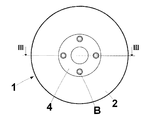
列挙した図を参照すると、ホイールリムC用の回転可能な支持グループ1が示されている。支持グループ1は、1組の環状構成要素、すなわち、中央窓2aを画定する回転可能な環状カウンタプレート2と、ホイールリム用の環状の停止又は支持プレート3とを備えている。停止又は支持プレート3は、使用中、回転可能なカウンタプレート2の上に設置されることが好ましく、環状カウンタプレート2に形成した中央窓2aに、好ましくは厳しい公差で、嵌め込まれることが可能であり、そこから所定の高さの端部3bによって上方へ延びた軸方向ハブ3aを有する(図3)。サイズがハブ3aよりも大きい環状当接プレート4がハブ3aに当接し、それによってその周りに周辺肩部4aを画定している。環状当接プレート4は、任意の適切な方法で、例えばハブにねじ込み可能なボルトBを用いてハブ3aに着脱自在に固定され得る。プレート2、3、及び4は中心軸x−xを中心として同軸に取り付けられる。
Referring to the enumerated figures, a
この構造では、環状カウンタプレート2は、当接プレート4の肩部4aに当接する前に、ハブの端部3bの長さに等しい最大長さまでハブ3aに沿って摺動することによって、停止又は支持プレート3に対して軸方向に移動し得る。
In this structure, the
環状カウンタプレート2及び停止又は支持プレート3はともに、好ましくは半分ずつ、複数の受入れ座部5の範囲を画定している。この受入れ座部5は、互いに角度的に隔たり、好ましくは2つのプレート2及び3の外縁の近くに設置され、そして同じ外径を有するのが有利である。
Both the
より具体的には、各受入れ座部は、2以上の傾斜面の壁を備え、これらは接線方向に向けられ、かつこれらの対応する受入れ座部の中間部分に向って集結している。したがって、各受入れ座部はその中間部分で大きいサイズを有し、サイズは接線方向において、中間部分から端部へ向って減少する。転動体、好ましくは鋼製の球体又はボール6が、プレート2と3との間の相互転がり摩擦連結のために各受入れ座部5に設置される。
More specifically, each receiving seat is provided with two or more inclined walls, which are oriented tangentially and concentrated towards the intermediate portion of their corresponding receiving seat. Thus, each receiving seat has a large size at its middle part, and the size decreases in the tangential direction from the middle part to the end. A rolling element, preferably a steel sphere or
図4を特に参照すると、本発明による回転可能なホイールリム支持グループ1は、軸x−xを垂直にして、底部8aを備える管状要素8によって、その上端で支持されており、任意の適切な型のタイヤ着脱装置MТの基部10から上方へ軸方向にグループ1を通ってそれよりも先に延びるほぼ垂直な制御軸9に、同軸状に固定されている。
With particular reference to FIG. 4, a rotatable wheel
制御軸は、その底部で、当技術分野で周知のように、モータM、例えば気圧又は電気モータによって回転させられることが可能であるのに対して、制御軸は、その上端において外部にねじ込まれ、ホイールリムCの幅に少なくとも等しい長さまでグループ1の上へ延びる。
The control shaft can be rotated at its bottom by a motor M, such as a pneumatic or electric motor, as is well known in the art, whereas the control shaft is screwed externally at its upper end. , Extending above the
ホイールリムCは、ホイールリムを下にある回転可能な支持グループ1の停止又は支持プレート3に押し付けるために、制御軸9にねじ込みが可能でありかつその外錐面でホイールリムCの中央穴12に当接するのに適した外錐面又は錐体11を有する要素を用いて、回転可能な支持グループ1に締め付けられる。したがって、停止又は支持プレート3は、管状要素8によって支持された下にあるカウンタプレート2に押し付けられる。
The wheel rim C can be screwed into the
制御軸9が下にあるモータによって回転させられる場合、制御軸9は制御軸9に固定された底部8aを介して、錐体11及び管状要素8の両方を回転に引き込み、それにより、カウンタプレート2が回転する。プレート2と3との間の摩擦により、停止又は支持プレート3もまた、ひいてはそれに締め付けられたホイールリムCも回転に引き込まれる。しかしながら、このことは、さまざまな受入れ座部5の中に設けられている球体6によって生じる。球体は、プレート2と3との間に割り込まされている状態で、停止から動作位置へ動かされるようにするために、プレート2及び3の横たわっている面に対して傾けられている傾斜平行面(少なくともプレート3の上面、及び少なくともプレート2の下面)に沿って、強制的に転がされる。
When the
球体又はボール6の強制転動により、互いから離れるプレート2及び3の相対運動が生じ、すなわち、ハブ部分3aにおいてプレート2内を摺動可能な上部プレート3は、上昇するように強制され、したがってホイールリムCをさらに締め付けるように強制され、ホイールリムCはその反対側で錐体11によって位置が保持される。
The forced rolling of the sphere or
制御軸9を回転させると、ホイールリムと回転可能な支持グループ1との間のロッキング作用が増大し、したがってホイールリムCは、回転の際に支持グループ1に堅固に固定される。
Rotating the
前記の本発明による回転可能な支持グループ1は、ホイールリムCの最適な固定作用を確保することが可能であり、ホイールリムCは、標準的なタイヤ着脱及びビード離脱作業中に、摺動することなく、安全にかつしっかりと回転に引き込まれる。その上に、同じ回転可能な支持グループ1は、ホイールリムCを支持する適切な回転可能なプレートを必要としない。
The above-described
制御軸9が停止すると、プレート2と3との間の球体6は、それらの停止位置へ戻り、それによってプレート2及び3がより近づくことを可能にする。
When the
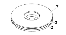
プレート3の停止及び支持面は、プレートとホイールリムCとの間により大きい摩擦を確保するために粗面化されることが有利である。必要に応じて、プレート3の停止及び支持面に、大きい摩擦係数を有する材料、例えばゴムで形成した1つ以上の環状ガスケットシール要素又はシール7(図3)を備え、好ましくはプレート3に接着される。
The stop and support surface of the
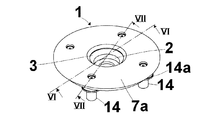
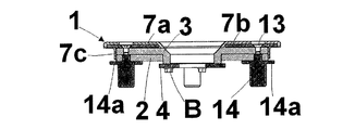
特に好ましい実施形態によれば、シール要素7は2つの環状同心シールを含み、一方のシール7aは停止及び支持プレート3と接触し、他方のシール7bはシール7aに形成した凹部に設置される(図5から図7)。環状シール7aはプレート3から突出する周辺管状縁を有する。管状縁において、管状部分7cが上方へ延びている。管状部分7cは、特にプレート2及び3が互いから離される場合に、粉末又は他の好ましくない物質がプレート2と3との間の隙間に入るのを防止するために、プレート2及び3を実質的に包むベルトとしての機能を果たすように設計されている。
According to a particularly preferred embodiment, the
シール7a及び7bは、プレート3に形成した適切なねじ穴にねじ込み可能な、複数のねじ13によって連結されることが好ましい(図5及び図7)。
The
図5から図7は、回転可能な支持グループ1と制御軸9に固定された管状要素8との間の係合手段の好ましい実施形態を示す。このような係合手段は、複数のほぞ又はピン要素14を備え、これらは回転可能な支持グループ1に沿って角度をずらしており、その一端でカウンタプレート2に形成した適切な穴と、その他端で管状要素8の前頭部に形成した適合可能な座部と係合するように設計されている。より良く安定させるために、各ピン要素14は中間フランジ14aを備え、中間フランジ14aは、使用中、カウンタプレート2と管状要素8との間に設置される。
FIGS. 5 to 7 show a preferred embodiment of the engagement means between the
前記の回転可能な支持グループは、特許請求の範囲によって規定される範囲内で多数の変更及び変形が可能である。 The rotatable support group can be modified and varied in many ways within the scope defined by the claims.
したがって、例えば、転動要素6を有する座部5は、一方のプレート2又は3に形成した複数の凹部5aによって置き換えられることが可能である。このような凹部は互いに角度をずらしており、各々はほぼ接線方向に延びる2つの集結傾斜面を画定するのに対して、他方のプレート3又は2は、互いに角度をずらした同数の複数の対応する突起5bを備えている。各々は、浮彫りで2つの集結傾斜面を画定し、それぞれ対応する凹部5aとの摺動摩擦による一致又は連結(図8)に適するようにしている。
Thus, for example, the
応力を受けたカウンタプレート2は、停止又は支持プレート3に対して制御軸9の回転方向に進むように強制され、したがって各凹部の傾斜面の1つの、対応する突起の対応する傾斜面に対する相互摺動が起きることになり、それによってプレート3はプレート2から離され(図9)、その結果、回転可能な支持グループ1のホイールリムCに対するロッキング作用が増大することになる。
The stressed
もちろん、制御軸9は、図4に示すように垂直か、又は水平に配置され得る。
Of course, the
Claims (19)
使用中、前記着脱自在のロッキング手段(11)に対して反対側で前記ホイールリム(C)に当接するように設計された少なくとも1つの対の環状プレート要素(2,3)であって、前記制御軸(9)に沿って、相互に向い合い、互いに接近及び後退できるように構成された環状プレート要素(2,3)と、
互いに角度を隔て、かつ前記環状プレート要素(2,3)の一方に部分的に、そして他方に部分的に形成された複数の摩擦係合手段(5,6,5a,5b)であって、一方の前記環状プレート要素における前記摩擦係合手段(5,6,5a,5b)の各々は、前記対のうち他方の前記環状プレート要素における対応する摩擦係合手段と協働するように設計され、それによって前記摩擦係合手段の1つが他の摩擦係合手段に対して角度をずらすときに、前記環状プレート要素(2,3)を互いに離すようにする摩擦係合手段(5,6,5a,5b)と、
前記制御軸(9)と前記環状プレート要素対の前記環状プレート要素(2,3)の一方との間における支持及び回転運動伝達手段(8,8a)とを備え、
前記支持及び回転運動伝達手段(8,8a)は、前記対の環状プレート要素(2、3)を自身の上端で支持するために、前記基部(10)から延びる管状部材(8)を備え、かつ前記制御軸(9)に固定されて回転する底部分(8a)を備え、
前記対の環状プレート要素(2,3)は、一方が環状カウンタプレート部材(2)で、他方が停止又は支持プレート部材(3)であり、
各対の前記一方の環状カウンタプレート部材(2)は中央窓(2a)を有し、前記管状部材(8)に面するように設計されているのに対して、前記他方の停止又は支持プレート部材(3)は、支持されるホイールリム(C)に面するように設計されており、かつ前記環状カウンタプレート部材(2)の前記中央窓(2a)に嵌め込み可能な軸方向ハブ(3a)を備えることを特徴とする回転可能なホイールリム支持グループ。 A base (10), a control shaft (9) extending from the base (10), and the wheel rim (C) engageable with a side of the control shaft (9) and the wheel rim (C) during use; A rotatable wheel rim support group designed to be attached to a tire detaching device (MТ) comprising a detachable locking means (11) for driving and a driving means (M) for the control shaft (9) There,
In use, at least one pair of annular plate elements (2, 3) designed to abut the wheel rim (C) on the opposite side to the removable locking means (11), An annular plate element (2, 3) configured to face each other and to approach and retract from each other along a control axis (9);
A plurality of frictional engagement means (5, 6, 5a, 5b) angled from each other and partially formed on one of the annular plate elements (2, 3) and partially on the other, each of said friction engagement means in one of said annular plate elements (5,6,5a, 5b) is designed to cooperate with frictional engagement means corresponding in the other of said annular plate elements of said pair Frictional engagement means (5, 6, 6) which cause the annular plate elements (2, 3) to move away from each other when one of the frictional engagement means shifts its angle relative to the other frictional engagement means. 5a, 5b)
Support and rotational motion transmitting means (8, 8a) between the control shaft (9) and one of the annular plate elements (2, 3) of the annular plate element pair ;
Said support and rotational movement transmitting means (8, 8a) comprise a tubular member (8) extending from said base (10) for supporting said pair of annular plate elements (2, 3) at its upper end; And a bottom portion (8a) fixed to the control shaft (9) and rotating,
The pair of annular plate elements (2, 3), one is an annular counter plate member (2) and the other is a stop or support plate member (3);
Each pair of said one annular counterplate member (2) has a central window (2a) and is designed to face said tubular member (8), whereas said other stop or support plate The member (3) is designed to face the wheel rim (C) to be supported and is an axial hub (3a) that can be fitted into the central window (2a) of the annular counterplate member (2) rotatable wheel rim support group, characterized in that it comprises a.
使用中、前記着脱自在のロッキング手段(11)に対して反対側で前記ホイールリム(C)に当接するように設計された少なくとも1つの対の環状プレート要素(2,3)であって、前記制御軸(9)に沿って、相互に向い合い、互いに接近及び後退できるように構成された環状プレート要素(2,3)と、In use, at least one pair of annular plate elements (2, 3) designed to abut the wheel rim (C) on the opposite side to the removable locking means (11), An annular plate element (2, 3) configured to face each other and to approach and retract from each other along a control axis (9);
互いに角度を隔て、かつ前記環状プレート要素(2,3)の一方に部分的に、そして他方に部分的に形成された複数の摩擦係合手段(5,6,5a,5b)であって、一方の前記環状プレート要素における前記摩擦係合手段(5,6,5a,5b)の各々は、前記対のうち他方の前記環状プレート要素における対応する摩擦係合手段と協働するように設計され、それによって前記摩擦係合手段の1つが他の摩擦係合手段に対して角度をずらすときに、前記環状プレート要素(2,3)を互いに離すようにする摩擦係合手段(5,6,5a,5b)と、A plurality of frictional engagement means (5, 6, 5a, 5b) angled from each other and partially formed on one of the annular plate elements (2, 3) and partially on the other, Each of the frictional engagement means (5, 6, 5a, 5b) in one of the annular plate elements is designed to cooperate with a corresponding frictional engagement means in the other annular plate element of the pair. Frictional engagement means (5, 6, 6) which cause the annular plate elements (2, 3) to move away from each other when one of the frictional engagement means shifts its angle relative to the other frictional engagement means. 5a, 5b)
前記制御軸(9)と前記環状プレート要素対の前記環状プレート要素(2,3)の一方との間における支持及び回転運動伝達手段(8,8a)とを備え、Support and rotational motion transmitting means (8, 8a) between the control shaft (9) and one of the annular plate elements (2, 3) of the annular plate element pair;
前記支持及び回転運動伝達手段(8,8a)は、前記対の環状プレート要素(2、3)を自身の上端で支持するために、前記基部(10)から延びる管状部材(8)を備え、かつ前記制御軸(9)に固定されて回転する底部分(8a)を備え、Said support and rotational movement transmitting means (8, 8a) comprise a tubular member (8) extending from said base (10) for supporting said pair of annular plate elements (2, 3) at its upper end; And a bottom portion (8a) fixed to the control shaft (9) and rotating,
前記対の環状プレート要素(2,3)は、一方が停止又は支持プレート部材(3)であり、One of the pair of annular plate elements (2, 3) is a stop or support plate member (3);
前記停止又は支持プレート部材(3)に、摩擦係数が大きい材料で形成された少なくとも1つの環状シール部材(7)が、前記ホイールリム(C)と接触するために設けられていることを特徴とする回転可能なホイールリム支持グループ。The stop or support plate member (3) is provided with at least one annular seal member (7) made of a material having a high coefficient of friction so as to come into contact with the wheel rim (C). A rotatable wheel rim support group.
Applications Claiming Priority (2)
| Application Number | Priority Date | Filing Date | Title |
|---|---|---|---|
| IT000059A ITVR20050059A1 (en) | 2005-05-16 | 2005-05-16 | GROUP OF SUPPORT AND ROTATION OF A RIM IN PARTICULAR FOR A MOUNTING-TIRE MACHINE. |
| ITVR2005A000059 | 2005-05-16 |
Publications (3)
| Publication Number | Publication Date |
|---|---|
| JP2006321481A JP2006321481A (en) | 2006-11-30 |
| JP2006321481A5 JP2006321481A5 (en) | 2009-05-07 |
| JP5000922B2 true JP5000922B2 (en) | 2012-08-15 |
Family
ID=36956774
Family Applications (1)
| Application Number | Title | Priority Date | Filing Date |
|---|---|---|---|
| JP2006135562A Active JP5000922B2 (en) | 2005-05-16 | 2006-05-15 | A rotatable wheel rim support group, especially for tire detachers |
Country Status (7)
| Country | Link |
|---|---|
| US (1) | US7293595B2 (en) |
| EP (1) | EP1724125B1 (en) |
| JP (1) | JP5000922B2 (en) |
| CN (1) | CN100572115C (en) |
| AT (1) | ATE528151T1 (en) |
| ES (1) | ES2374928T3 (en) |
| IT (1) | ITVR20050059A1 (en) |
Families Citing this family (19)
| Publication number | Priority date | Publication date | Assignee | Title |
|---|---|---|---|---|
| US8011412B2 (en) * | 2007-01-04 | 2011-09-06 | Melzo Innovations | Tire removal aid for large tires to minimize / eliminate scuffing of the wheel |
| JP4970970B2 (en) * | 2007-02-01 | 2012-07-11 | 東洋電機製造株式会社 | Jig for in-wheel motor unit |
| US8307874B1 (en) | 2008-01-25 | 2012-11-13 | Hunter Engineering Company | Tire changing method and machine with angularly positionable drive axis |
| CN101844485B (en) * | 2010-06-02 | 2012-05-23 | 营口大力汽保设备科技有限公司 | Quick-locking device |
| CN102588399A (en) * | 2011-01-06 | 2012-07-18 | 周立新 | Clamp device and mounting and dismounting device for clamp device |
| US9283820B1 (en) * | 2011-05-20 | 2016-03-15 | Hunter Engineering Company | Wheel assembly service machine with back cone center clamp mechanism |
| ITBO20110300A1 (en) | 2011-05-24 | 2012-11-25 | Corghi Spa | A CENTERING DEVICE FOR THE RIM OF A WHEEL ON THE WHEEL-HOLDING ASSEMBLY OF A TIRE CHANGER MACHINE. |
| US8544520B2 (en) * | 2011-06-28 | 2013-10-01 | Snap-On Equipment Srl A Unico Socio | Automatic rim centering system for a tyre changing machine |
| ITMO20110185A1 (en) * | 2011-07-26 | 2013-01-27 | Giuliano Group Spa | DEVICE FOR LOCKING WHEEL RIMS FOR VEHICLES ON CARS, MULTI-TIRE OR SIMILAR MACHINES |
| US20130192768A1 (en) * | 2012-01-31 | 2013-08-01 | Chih-Liang Peng | Structure of tire changer |
| US20140034249A1 (en) * | 2012-08-01 | 2014-02-06 | Paolo SOTGIU | Wheel-clamping device for a wheel-service-machine and method for reversibly clamping a wheel on a wheel-clamping device for a wheel-service-machine |
| US9038692B2 (en) | 2012-03-12 | 2015-05-26 | Snap-On Equipment Srl A Unico Socio | Wheel-clamping device for a wheel-service-machine and method for reversibly clamping a wheel on a wheel-clamping device for a wheel-service-machine |
| EP2687385A1 (en) | 2012-07-20 | 2014-01-22 | Snap-on Equipment Srl a unico socio | Drive assembly for tire service machines |
| KR101659198B1 (en) * | 2012-08-06 | 2016-09-22 | 미츠비시 쥬우고오 마시나리 테크노로지 가부시키가이샤 | Tire holding apparatus |
| JP2014162271A (en) * | 2013-02-22 | 2014-09-08 | Altlife Co Ltd | Tire fixation mechanism and tire changer |
| CN110228327B (en) * | 2019-05-27 | 2024-04-26 | 南通华夏飞机工程技术股份有限公司 | Aircraft tire erection equipment |
| CN112026455B (en) * | 2020-08-21 | 2022-07-12 | 刘涛 | Swift manual locking wheel hub device |
| CN113561088B (en) * | 2021-07-25 | 2023-03-24 | 上海远迹新材料有限公司 | Balanced frock of reprocessing of wheel hub |
| CN113733812B (en) * | 2021-11-08 | 2022-02-18 | 杭州骑遇科技有限公司 | Wheel device suitable for new energy automobile |
Family Cites Families (7)
| Publication number | Priority date | Publication date | Assignee | Title |
|---|---|---|---|---|
| DE3334203A1 (en) * | 1983-09-22 | 1985-04-18 | Continental Gummi-Werke Ag, 3000 Hannover | AIR TIRE ASSEMBLY DEVICE |
| IT222810Z2 (en) * | 1990-03-23 | 1995-05-08 | Butler Eng & Marketing | TIRE CHANGER MACHINE |
| DE4437566C2 (en) * | 1993-10-22 | 1997-06-05 | Bridgestone Corp | Fastening device for a tire wheel assembly on a wheel balancing device |
| CN2206221Y (en) * | 1994-09-26 | 1995-08-30 | 吴伟东 | Machine for mounting or removing rim tyre |
| IT1289137B1 (en) * | 1996-10-22 | 1998-09-25 | Butler Eng & Marketing | TIRE CHANGER MACHINE |
| IT1319468B1 (en) * | 2000-05-22 | 2003-10-10 | Corghi Spa | AUTOMATIC Bead breaker device for tire changers, tire changers so equipped |
| CN2657959Y (en) * | 2003-11-21 | 2004-11-24 | 魏恩贵 | Auxiliary device of tyre mounting and dismounting machine |
-
2005
- 2005-05-16 IT IT000059A patent/ITVR20050059A1/en unknown
-
2006
- 2006-05-10 AT AT06009664T patent/ATE528151T1/en not_active IP Right Cessation
- 2006-05-10 EP EP06009664A patent/EP1724125B1/en active Active
- 2006-05-10 ES ES06009664T patent/ES2374928T3/en active Active
- 2006-05-15 JP JP2006135562A patent/JP5000922B2/en active Active
- 2006-05-16 US US11/434,205 patent/US7293595B2/en active Active
- 2006-05-16 CN CNB2006100808004A patent/CN100572115C/en active Active
Also Published As
| Publication number | Publication date |
|---|---|
| US20060266481A1 (en) | 2006-11-30 |
| EP1724125B1 (en) | 2011-10-12 |
| EP1724125A1 (en) | 2006-11-22 |
| CN1876411A (en) | 2006-12-13 |
| ES2374928T3 (en) | 2012-02-23 |
| CN100572115C (en) | 2009-12-23 |
| ATE528151T1 (en) | 2011-10-15 |
| US7293595B2 (en) | 2007-11-13 |
| ITVR20050059A1 (en) | 2006-11-17 |
| JP2006321481A (en) | 2006-11-30 |
Similar Documents
| Publication | Publication Date | Title |
|---|---|---|
| JP5000922B2 (en) | A rotatable wheel rim support group, especially for tire detachers | |
| JP2006321481A5 (en) | ||
| KR102139421B1 (en) | Grinder wheel holder for hand grinder | |
| US10092992B2 (en) | Polishing apparatus, polishing head, and retainer ring | |
| US6042461A (en) | Mounting assembly | |
| US10682736B2 (en) | Accessory clamp and spindle lock mechanism for power tool | |
| US12048982B2 (en) | Grinding head for floor grinding machine and method of assembling a grinding head, setting a belt tensioner, servicing, assembling or disassembling a belt pulley for a floor grinding machine | |
| WO2017110156A1 (en) | Grinding device and grinding implement for said grinding device | |
| KR102232781B1 (en) | Combination structure of electric drive wheel for wheelchair | |
| US7513034B2 (en) | Rim disk assembling device for full face wheel for vehicle | |
| WO2006092834A1 (en) | Turntable | |
| US3818968A (en) | Apparatus for use in mounting tires on and removing tires from wheel rims | |
| CA2712464C (en) | A coupling | |
| ITBO20110300A1 (en) | A CENTERING DEVICE FOR THE RIM OF A WHEEL ON THE WHEEL-HOLDING ASSEMBLY OF A TIRE CHANGER MACHINE. | |
| US3823757A (en) | Apparatus for use in mounting tires on and removing tires from wheel rims | |
| JP2001287893A (en) | Screw type jack device | |
| US3948306A (en) | Tire removing tool | |
| JP6449194B2 (en) | Polishing device, polishing head, and retainer ring | |
| US11701751B2 (en) | Grinding head for floor grinding machine and method of assembling a grinding head, setting a belt tensioner, servicing, assembling or disassembling a belt pulley for a floor grinding machine | |
| CN213386496U (en) | Slewing device and transmission mechanism thereof | |
| US964462A (en) | Vehicle-wheel. | |
| KR20070106621A (en) | Turntable | |
| KR19980020847U (en) | C-hook for overhead crane with reflector | |
| JPS58155175A (en) | Apparatus for bearing shaft of grinding wheel |
Legal Events
| Date | Code | Title | Description |
|---|---|---|---|
| A521 | Request for written amendment filed |
Free format text: JAPANESE INTERMEDIATE CODE: A523 Effective date: 20060822 |
|
| A521 | Request for written amendment filed |
Free format text: JAPANESE INTERMEDIATE CODE: A523 Effective date: 20090318 |
|
| A621 | Written request for application examination |
Free format text: JAPANESE INTERMEDIATE CODE: A621 Effective date: 20090318 |
|
| A131 | Notification of reasons for refusal |
Free format text: JAPANESE INTERMEDIATE CODE: A131 Effective date: 20111025 |
|
| TRDD | Decision of grant or rejection written | ||
| A01 | Written decision to grant a patent or to grant a registration (utility model) |
Free format text: JAPANESE INTERMEDIATE CODE: A01 Effective date: 20120515 |
|
| A01 | Written decision to grant a patent or to grant a registration (utility model) |
Free format text: JAPANESE INTERMEDIATE CODE: A01 |
|
| A61 | First payment of annual fees (during grant procedure) |
Free format text: JAPANESE INTERMEDIATE CODE: A61 Effective date: 20120517 |
|
| R150 | Certificate of patent or registration of utility model |
Ref document number: 5000922 Country of ref document: JP Free format text: JAPANESE INTERMEDIATE CODE: R150 Free format text: JAPANESE INTERMEDIATE CODE: R150 |
|
| FPAY | Renewal fee payment (event date is renewal date of database) |
Free format text: PAYMENT UNTIL: 20150525 Year of fee payment: 3 |
|
| R250 | Receipt of annual fees |
Free format text: JAPANESE INTERMEDIATE CODE: R250 |
|
| R250 | Receipt of annual fees |
Free format text: JAPANESE INTERMEDIATE CODE: R250 |
|
| R250 | Receipt of annual fees |
Free format text: JAPANESE INTERMEDIATE CODE: R250 |
|
| R250 | Receipt of annual fees |
Free format text: JAPANESE INTERMEDIATE CODE: R250 |
|
| R250 | Receipt of annual fees |
Free format text: JAPANESE INTERMEDIATE CODE: R250 |
|
| R250 | Receipt of annual fees |
Free format text: JAPANESE INTERMEDIATE CODE: R250 |
|
| R250 | Receipt of annual fees |
Free format text: JAPANESE INTERMEDIATE CODE: R250 |
|
| R250 | Receipt of annual fees |
Free format text: JAPANESE INTERMEDIATE CODE: R250 |
|
| R250 | Receipt of annual fees |
Free format text: JAPANESE INTERMEDIATE CODE: R250 |
|
| R250 | Receipt of annual fees |
Free format text: JAPANESE INTERMEDIATE CODE: R250 |