US10090906B2 - PMI reporting for a set of ports - Google Patents
PMI reporting for a set of ports Download PDFInfo
- Publication number
- US10090906B2 US10090906B2 US15/522,842 US201515522842A US10090906B2 US 10090906 B2 US10090906 B2 US 10090906B2 US 201515522842 A US201515522842 A US 201515522842A US 10090906 B2 US10090906 B2 US 10090906B2
- Authority
- US
- United States
- Prior art keywords
- reference signals
- ports
- report
- network node
- wireless device
- Prior art date
- Legal status (The legal status is an assumption and is not a legal conclusion. Google has not performed a legal analysis and makes no representation as to the accuracy of the status listed.)
- Active
Links
Images


Classifications
-
- H—ELECTRICITY
- H04—ELECTRIC COMMUNICATION TECHNIQUE
- H04B—TRANSMISSION
- H04B7/00—Radio transmission systems, i.e. using radiation field
- H04B7/02—Diversity systems; Multi-antenna system, i.e. transmission or reception using multiple antennas
- H04B7/04—Diversity systems; Multi-antenna system, i.e. transmission or reception using multiple antennas using two or more spaced independent antennas
- H04B7/06—Diversity systems; Multi-antenna system, i.e. transmission or reception using multiple antennas using two or more spaced independent antennas at the transmitting station
- H04B7/0613—Diversity systems; Multi-antenna system, i.e. transmission or reception using multiple antennas using two or more spaced independent antennas at the transmitting station using simultaneous transmission
- H04B7/0615—Diversity systems; Multi-antenna system, i.e. transmission or reception using multiple antennas using two or more spaced independent antennas at the transmitting station using simultaneous transmission of weighted versions of same signal
- H04B7/0619—Diversity systems; Multi-antenna system, i.e. transmission or reception using multiple antennas using two or more spaced independent antennas at the transmitting station using simultaneous transmission of weighted versions of same signal using feedback from receiving side
- H04B7/0636—Feedback format
- H04B7/0639—Using selective indices, e.g. of a codebook, e.g. pre-distortion matrix index [PMI] or for beam selection
-
- H—ELECTRICITY
- H04—ELECTRIC COMMUNICATION TECHNIQUE
- H04B—TRANSMISSION
- H04B7/00—Radio transmission systems, i.e. using radiation field
- H04B7/02—Diversity systems; Multi-antenna system, i.e. transmission or reception using multiple antennas
- H04B7/04—Diversity systems; Multi-antenna system, i.e. transmission or reception using multiple antennas using two or more spaced independent antennas
- H04B7/0413—MIMO systems
- H04B7/0456—Selection of precoding matrices or codebooks, e.g. using matrices antenna weighting
-
- H—ELECTRICITY
- H04—ELECTRIC COMMUNICATION TECHNIQUE
- H04B—TRANSMISSION
- H04B7/00—Radio transmission systems, i.e. using radiation field
- H04B7/02—Diversity systems; Multi-antenna system, i.e. transmission or reception using multiple antennas
- H04B7/04—Diversity systems; Multi-antenna system, i.e. transmission or reception using multiple antennas using two or more spaced independent antennas
- H04B7/06—Diversity systems; Multi-antenna system, i.e. transmission or reception using multiple antennas using two or more spaced independent antennas at the transmitting station
-
- H—ELECTRICITY
- H04—ELECTRIC COMMUNICATION TECHNIQUE
- H04L—TRANSMISSION OF DIGITAL INFORMATION, e.g. TELEGRAPHIC COMMUNICATION
- H04L27/00—Modulated-carrier systems
- H04L27/18—Phase-modulated carrier systems, i.e. using phase-shift keying
Definitions
- Embodiments presented herein relate to methods, a wireless device, a network node, computer programs, and a computer program product for precoding matrix indicator reporting for a set of ports.
- communications networks there may be a challenge to obtain good performance and capacity for a given communications protocol, its parameters and the physical environment in which the communications network is deployed.
- the use of network nodes employing multi-antenna techniques has the potential to increase the performance of the communications network a whole order of magnitude.
- several gains can be harvested, such as increased spectral efficiency, reduced interference, increased link reliability in terms of diversity, and so on.
- Communications networks employing network nodes with more than one transmit antenna can be categorized into two main groups based on how each antenna element can be controlled; digital beamforming and analogue beamforming, respectively.
- DgBF digital beamforming
- analogue beamforming With analogue beamforming (AnBF) the transmitted signal from each antenna cannot be set to any arbitrary value due to simplified hardware.
- the transmitted complex-valued symbols from the antennas have the same amplitude and only differ from one another in a fixed phase, linearly.
- Precoding is a generalization of beamforming to support multi-stream (or multi-layer) transmission in multi-antenna wireless communications.
- Digital beamforming may be regarded as giving more freedom in selecting appropriate precoders but generally requires more advanced, and possibly more expensive, hardware. It is foreseen that in future radio systems, a combination of digital beamforming and analogue beamforming can be used.
- an antenna array comprising antenna panels (herein also referred to as ports) can be individually controlled with AnBF and the antenna panels can be jointly controlled with DgBF.
- AnBF can be applied, and for the groups of antennas (belonging to each antenna panel), DgBF can be applied.
- the wireless device can be configured to report which precoding and rank the wireless device estimates is best to use.
- the precoders are associated with reference signals transmitted by the radio access network node.
- the set of available precoders is denoted a codebook, which is reported using an index and a rank, e.g. a Precoder Matrix indicator (PMI) and a Rank Indicator (RI).
- PMI Precoder Matrix indicator
- RI Rank Indicator
- An object of embodiments herein is to provide efficient handling of reference signal reporting.
- a method for precoding matrix indicator (PMI) reporting for a set of ports is performed by a wireless device.
- the method comprises receiving reference signals, the reference signals having been transmitted from a set of ports of a network node.
- the method comprises determining PMI information for the received reference signals.
- the method comprises transmitting the PMI information in a report to the network node, wherein the report comprises a combination of identifications of ports from the set of ports and identifications of the reference signals such that an identification of each port is paired with a respective identification of at most one of the reference signals.
- a wireless device for PMI reporting for a set of ports.
- the wireless device comprises processing circuitry.
- the processing circuitry is configured to cause the wireless device to receive reference signals, the reference signals having been transmitted from a set of ports of a network node.
- the processing circuitry is configured to cause the wireless device to determine PMI information for the received reference signals.
- the processing circuitry is configured to cause the wireless device to transmit the PMI information in a report to the network node, wherein the report comprises a combination of identifications of ports from the set of ports and identifications of the reference signals such that an identification of each port is paired with a respective identification of at most one of the reference signals.
- a computer program for PMI reporting for a set of ports comprising computer program code which, when run on processing circuitry of a wireless device, causes the wireless device to perform a method according to the first aspect.
- a method for PMI reporting for a set of ports is performed by a network node.
- the method comprises transmitting reference signals on a set of ports.
- the method comprises receiving PMI information in a report from a wireless device for the set of ports.
- the report comprises a combination of identifications of ports from the set of ports and identifications of the reference signals such that an identification of each port is paired with a respective identification of at most one of the reference signals.
- a network node for PMI reporting for a set of ports comprises processing circuitry.
- the processing circuitry is configured to cause the network node to transmit reference signals on a set of ports.
- the processing circuitry is configured to cause the network node to receive PMI information in a report from a wireless device for the set of ports.
- the report comprises a combination of identifications of ports from the set of ports and identifications of the reference signals such that an identification of each port is paired with a respective identification of at most one of the reference signals.
- a computer program for PMI reporting for a set of ports comprising computer program code which, when run on processing circuitry of a network node, causes the network node to perform a method according to the fourth aspect.
- a seventh aspect there is presented a computer program product comprising a computer program according to at least one of the third aspect and the sixth aspect and a computer readable means on which the computer program is stored.
- wireless device wireless device
- network node network node
- the above disclosed methods, wireless device, network node, computer programs, and computer program product makes it possible for the wireless device to perform a simultaneous beam scanning and PMI reporting procedure for a set of ports with a flexible beam-forming.
- This in turn enables the use of simplified hardware where different beam directions are possible, but where simultaneous use of two or more beam directions is not possible.
- the herein disclosed method for PMI reporting captures hardware architecture restrictions whilst enabling precoder selection to capture multipath propagations.
- any feature of the first, second, third, fourth, fifth, sixth and seventh aspects may be applied to any other aspect, wherever appropriate.
- any advantage of the first aspect may equally apply to the second, third, fourth, fifth, sixth, and/or seventh aspect, respectively, and vice versa.
- FIG. 1 is a schematic diagram illustrating a communication network according to embodiments
- FIG. 2 a is a schematic diagram showing functional units of a wireless device according to an embodiment
- FIG. 2 b is a schematic diagram showing functional modules of a wireless device according to an embodiment
- FIG. 3 a is a schematic diagram showing functional units of a network node according to an embodiment
- FIG. 3 b is a schematic diagram showing functional modules of a network node according to an embodiment
- FIG. 4 shows one example of a computer program product comprising computer readable means according to an embodiment
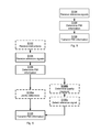
- FIGS. 5, 6, 7, and 8 are flowcharts of methods according to embodiments
- FIG. 9 is a schematic illustration of a precoding matrix indicator array according to an embodiment.
- FIGS. 10, 11, and 12 are schematic illustration of precoding matrix indicator reporting according to embodiments.
- FIG. 1 is a schematic diagram illustrating a communications network 100 where embodiments presented herein can be applied.
- the communications network 100 comprises a radio access network node 110 providing network access to a wireless device 200 within a cell, or coverage region, 120 by means of transmitting and receiving signals in an antenna system in m directional beams 150 a , 150 b , . . . , 150 m .
- the radio access network node 110 can be a radio base station, a base transceiver station, a node B, an evolved node B, or an access point.
- the wireless device 200 transmits and receives signals in an antenna system in n directional beams 160 a , 160 b , . . . , 160 n .
- the wireless device 200 may be a portable wireless device, a mobile station, a mobile phone, a handset, a wireless local loop phone, a user equipment (UE), a smartphone, a laptop computer, a tablet computer, a wireless modem, or a sensor device.
- a portable wireless device a mobile station, a mobile phone, a handset, a wireless local loop phone, a user equipment (UE), a smartphone, a laptop computer, a tablet computer, a wireless modem, or a sensor device.
- the radio access network node 110 is operatively connected to a core network 130 , and the core network is in turn operatively connected to a service network 140 , such as the Internet.
- a wireless device 200 having an operative connection to the radio access network node 120 may thereby exchange data (i.e., receive data packets and send data packets) and access services provided by the service network 140 .
- the communications network 100 further comprises a network node 300 .
- the network node 300 may be located in the radio access network, for example being co-located with the radio access network node 110 , or be provided in the core network 130 .
- the network node 300 will be further described below.
- a particular antenna port (antenna panel) can be configured with different directional beams, but it is not possible to simultaneously transmit signals in two or more different directions at the same time. This is the case since in AnBF only a linear phase-offset between the antenna elements of the panel can be varied, and hence the antenna panel can only point in one spatial direction at a time.
- DgBF can only be applied over groups of antennas (antenna panels), and only AnBF can be applied on each individual antenna panel, which limits the number of simultaneous spatial directions the antenna system can provide. This is the case even though the antenna system has a large number of antennas.
- Each reference signals may be transmitted in a separate beam and hence reference signals 0, 1, . . . , M may correspond to directional beams 0, 1, . . . , M.
- the radio access network node 110 would need to limit the reference signals to a set of references signals that is possible for the wireless device 200 to combine, e.g. one reference signal per antenna panel. Hence a time consuming and inefficient search would be necessary in order for the wireless device 200 to report the PMI.
- the embodiments disclosed herein thus relate to mechanisms for PMI reporting for a set of ports.
- a wireless device 200 a method performed by the wireless device 200 , a computer program product comprising code, for example in the form of a computer program, that when run on processing circuitry of the wireless device 200 , causes the wireless device 200 to perform the method.
- a network node 300 a method performed by the network node 300 , and a computer program product comprising code, for example in the form of a computer program, that when run on processing circuitry of the network node 300 , causes the network node 300 to perform the method.
- FIG. 2 a schematically illustrates, in terms of a number of functional units, the components of a wireless device 200 according to an embodiment.
- Processing circuitry 210 is provided using any combination of one or more of a suitable central processing unit (CPU), multiprocessor, or microcontroller, digital signal processor (DSP), etc., capable of executing software instructions stored in a computer program product 410 a (as in FIG. 4 ), e.g. in the form of a storage medium 230 .
- the processing circuitry 210 may alternatively be provided by at least one application specific integrated circuit (ASIC), or at least one field programmable gate array (FPGA).
- ASIC application specific integrated circuit
- FPGA field programmable gate array
- the processing circuitry 210 is configured to cause the wireless device 200 to perform a set of operations, or steps, S 102 -S 108 . These operations, or steps, S 102 -S 108 will be disclosed below.
- the storage medium 230 may store the set of operations
- the processing circuitry 210 may be configured to retrieve the set of operations from the storage medium 230 to cause the wireless device 200 to perform the set of operations.
- the set of operations may be provided as a set of executable instructions.
- the processing circuitry 210 is thereby arranged to execute methods as herein disclosed.
- the storage medium 230 may also comprise persistent storage, which, for example, can be any single one or combination of magnetic memory, optical memory, solid state memory or even remotely mounted memory.
- the wireless device 200 may further comprise a communications interface 220 for communications with at least one radio access network node 110 and at least one network node 300 .
- the communications interface 220 may comprise one or more transmitters and receivers, comprising analogue and digital components and a suitable number of antennas for wireless communications and ports for wireline communications.
- the processing circuitry 210 controls the general operation of the wireless device 200 e.g. by sending data and control signals to the communications interface 220 and the storage medium 230 , by receiving data and reports from the communications interface 220 , and by retrieving data and instructions from the storage medium 230 .
- Other components, as well as the related functionality, of the wireless device 200 are omitted in order not to obscure the concepts presented herein.
- FIG. 2 b schematically illustrates, in terms of a number of functional modules, the components of a wireless device 200 according to an embodiment.
- the wireless device 200 of FIG. 2 b may further comprise a number of optional functional modules, such as a select module 210 d configured to perform below step S 106 c .
- the functionality of each functional module 210 a - 210 d will be further disclosed below in the context of which the functional modules 210 a - 210 d may be used.
- each functional module 210 a - 210 d may be implemented in hardware or in software.
- one or more or all functional modules 210 a - 210 d may be implemented by the processing circuitry 210 , possibly in cooperation with functional units 220 and/or 230 .
- the processing circuitry 210 may thus be arranged to from the storage medium 230 fetch instructions as provided by a functional module 210 a - 210 d and to execute these instructions, thereby performing any steps as will be disclosed hereinafter.
- FIG. 3 a schematically illustrates, in terms of a number of functional units, the components of a network node 300 according to an embodiment.
- Processing circuitry 310 is provided using any combination of one or more of a suitable central processing unit (CPU), multiprocessor, microcontroller, digital signal processor (DSP), etc., capable of executing software instructions stored in a computer program product 410 b (as in FIG. 4 ), e.g. in the form of a storage medium 330 .
- the processing circuitry 310 may alternatively be provided by at least one application specific integrated circuit (ASIC), or at least one field programmable gate array (FPGA).
- ASIC application specific integrated circuit
- FPGA field programmable gate array
- the processing circuitry 310 is configured to cause the network node 300 to perform a set of operations, or steps, S 202 -S 206 . These operations, or steps, S 202 -S 206 will be disclosed below.
- the storage medium 330 may store the set of operations
- the processing circuitry 310 may be configured to retrieve the set of operations from the storage medium 330 to cause the network node 300 to perform the set of operations.
- the set of operations may be provided as a set of executable instructions.
- the processing circuitry 310 is thereby arranged to execute methods as herein disclosed.
- the storage medium 330 may also comprise persistent storage, which, for example, can be any single one or combination of magnetic memory, optical memory, solid state memory or even remotely mounted memory.
- the network node 300 may further comprise a communications interface 320 for communications with at least one wireless device 200 and at least one radio access network node no, and, optionally entities and devices of the core network 130 and the service network 140 .
- the communications interface 320 may comprise one or more transmitters and receivers, comprising analogue and digital components and a suitable number of antennas for wireless communications and ports for wireline communications.
- the processing circuitry 310 controls the general operation of the network node 300 e.g. by sending data and control signals to the communications interface 320 and the storage medium 330 , by receiving data and reports from the communications interface 320 , and by retrieving data and instructions from the storage medium 330 .
- Other components, as well as the related functionality, of the network node 300 are omitted in order not to obscure the concepts presented herein.
- FIG. 3 b schematically illustrates, in terms of a number of functional modules, the components of a network node 300 according to an embodiment.
- the network node 300 of FIG. 3 b comprises a number of functional modules; a transmit module 310 a configured to perform below step S 204 , and a receive module 310 b configured to perform below step S 206 .
- the network node 300 of FIG. 3 b may further comprises a number of optional functional modules, such as a provide module 310 c configured to perform below step S 202 .
- the functionality of each functional module 310 a - 310 c will be further disclosed below in the context of which the functional modules 310 a - 310 c may be used.
- each functional module 310 a - 310 c may be implemented in hardware or in software.
- one or more or all functional modules 310 a - 310 c may be implemented by the processing circuitry 310 , possibly in cooperation with functional units 320 and/or 330 .
- the processing circuitry 310 may thus be arranged to from the storage medium 330 fetch instructions as provided by a functional module 310 a - 310 c and to execute these instructions, thereby performing any steps as will be disclosed hereinafter.
- the network node 300 may be provided as a standalone device or as a part of at least one further device.
- the network node 300 may be provided in a radio access network node 110 , in another node of the radio access network, or in a node of the core network 130 .
- functionality of the network node 300 may be distributed between at least two devices, or nodes. These at least two nodes, or devices, may either be part of the same network part (such as the radio access network or the core network) or may be spread between at least two such network parts.
- instructions that are required to be performed in real time may be performed in a device, or node, operatively closer to the radio access network than instructions that are not required to be performed in real time.
- at least part of the network node 300 may reside in the radio access network, such as in the radio access network node 110 , for cases when embodiments as disclosed herein are performed in real time.
- a first portion of the instructions performed by the network node 300 may be executed in a first device, and a second portion of the of the instructions performed by the network node 300 may be executed in a second device; the herein disclosed embodiments are not limited to any particular number of devices on which the instructions performed by the network node 300 may be executed.
- the methods according to the herein disclosed embodiments are suitable to be performed by a network node 300 residing in a cloud computational environment. Therefore, although a single processing circuitry 310 is illustrated in FIG. 3 a the processing circuitry 310 may be distributed among a plurality of devices, or nodes. The same applies to the functional modules 310 a - 310 c of FIG. 3 b and the computer program 420 b of FIG. 4 (see below).
- FIG. 4 shows one example of a computer program product 410 a , 410 b comprising computer readable means 430 .
- a computer program 420 a can be stored, which computer program 420 a can cause the processing circuitry 210 and thereto operatively coupled entities and devices, such as the communications interface 220 and the storage medium 230 , to execute methods according to embodiments described herein.
- the computer program 420 a and/or computer program product 410 a may thus provide means for performing any steps of the wireless device 200 as herein disclosed.
- a computer program 420 b can be stored, which computer program 420 b can cause the processing circuitry 310 and thereto operatively coupled entities and devices, such as the communications interface 320 and the storage medium 330 , to execute methods according to embodiments described herein.
- the computer program 420 b and/or computer program product 410 b may thus provide means for performing any steps of the network node 300 as herein disclosed.
- the computer program product 410 a , 410 b is illustrated as an optical disc, such as a CD (compact disc) or a DVD (digital versatile disc) or a Blu-Ray disc.
- the computer program product 410 a , 410 b could also be embodied as a memory, such as a random access memory (RAM), a read-only memory (ROM), an erasable programmable read-only memory (EPROM), or an electrically erasable programmable read-only memory (EEPROM) and more particularly as a non-volatile storage medium of a device in an external memory such as a USB (Universal Serial Bus) memory or a Flash memory, such as a compact Flash memory.
- RAM random access memory
- ROM read-only memory
- EPROM erasable programmable read-only memory
- EEPROM electrically erasable programmable read-only memory
- the computer program 420 a , 420 b is here schematically shown as a track on the depicted optical disk, the computer program 420 a , 420 b can be stored in any way which is suitable for the computer program product 410 a , 410 b.
- FIGS. 5 and 6 are flow charts illustrating embodiments of methods for PMI reporting for a set of ports as performed by the wireless device 200 .
- FIGS. 7 and 8 are flow charts illustrating embodiments of methods for PMI reporting for a set of ports as performed by the network node 300 .
- the methods are advantageously provided as computer programs 420 a , 420 b.
- FIG. 5 illustrating a method for PMI reporting for a set of ports as performed by the wireless device 200 according to an embodiment.
- a network node 300 transmits reference signals.
- the wireless device 200 is therefore configured to, in a step S 104 , receive reference signals.
- the reference signals have been transmitted from a set of ports of the network node 300 . Examples of such reference signals will be provided below.
- the receive module 210 a may comprise instructions that when executed by the wireless device 200 causes the processing circuitry 210 , possibly in collaboration with the communications interface 200 and the storage medium 230 , to receive the reference signals in order for the wireless device 200 to perform step S 104 .
- the wireless device 200 is configured to, in a step S 106 , determine PMI information for the received reference signals. Different embodiments of how the wireless device 200 can determine PMI information will be disclosed below.
- the determine module 210 b may comprise instructions that when executed by the wireless device 200 causes the processing circuitry 210 , possibly in collaboration with the communications interface 200 and the storage medium 230 , to determine the PMI information in order for the wireless device 200 to perform step S 106 .
- the wireless device 200 is then configured to, in a step S 108 , transmit the PMI information in a report to the network node 300 .
- the transmit module 210 C may comprise instructions that when executed by the wireless device 200 causes the processing circuitry 210 , possibly in collaboration with the communications interface 200 and the storage medium 230 , to transmit the PMI information in order for the wireless device 200 to perform step S 108 .
- the report thus defines the PMI information,
- the report comprises a combination of identifications of ports from the set of ports and identifications of the reference signals such that an identification of each port is paired with a respective identification of at most one of the reference signals. Different embodiments of what PMI information the report may comprise, and how the PMI information may be represented in the report, will be disclosed below.
- FIG. 10 illustrates a report 1020 of PMI information determined as in step S 106 from PMI information 1010 , where in the PMI information 1010 only one entry per port is non-zero.
- FIG. 6 illustrating methods for PMI reporting for a set of ports as performed by the wireless device 200 according to further embodiments.
- the network node 300 may provide the wireless device 200 with instructions how to report the PMI information.
- the wireless device 200 is configured to, in a step S 102 , receive instructions how to report the PMI information from the network node 300 . Further properties of these instructions and how the wireless device 200 may act on the instructions will be disclosed below with reference to the network node 300 .
- the wireless device 200 can evaluate both which reference signal should be transmitted on each port (and/or which beam direction each ports should be transmitted in) and also how to combine the different ports; in some implementations a pre-coder is a beam-forming vector, comprising the phase offsets to use for the different ports to form a high gain antenna using the picked reference signals (and/or directions).
- the PMI information comprises phase offset information related to the received reference signals such that each identification of at most one of the reference signals is paired with a phase offset value of the at most one of the reference signals.
- precoder code-book could be used, for example comprising higher rank pre-coders rather than a rank 1 beam-former.
- precoder and reference signal reporting could be of any know type; given that for the subset of ports used for the PMI reporting, also a reference signal is given for each of the ports that the PMI information is calculated for.
- the precoding can capture multipath channels.
- the phase offset information has at least rank 2, and each identification of at most one of the reference signals is paired with as many phase offset values of the at most one of the reference signals as the rank.
- a restriction on the PMI codebook based on the hardware limitation of the antenna systems of the network node 300 and the wireless device 200 can thereby be enforced.
- the reporting of the PMI information may thereby result in not allowing a precoding codebook to be selected that allows for beam combinations that are physically not available, i.e., not allowing reference signals (and/or beam directions) stemming from the same port to be used simultaneously.
- the codebook is in this case restricted to n ⁇ m ⁇ 6 entries at most, which is smaller than 2 n ⁇ m for considered values of n and m.
- One codebook restriction can thus be formulated using a matrix representation of the precoder, as in FIG. 9 , and requiring every row in the precoder matrix to have one (and only one) non-zero element. Other embodiments will be disclosed below.
- each phase offset value can take a value from a binary set, such as from the binary set ⁇ 1,1 ⁇ , or from a M-valued set, where M>2, such as from a set of M-PSK values.
- M-PSK Phase Shift Keying
- the number of selectable ports is further restricted.
- the restriction can, for example, be based on load and/or priority of wireless devices 200 served by the network node 200 .
- Such restrictions could for example be that only N1 rows in the precoder matrix are allowed to have non-zero elements, where the integer N1 is a fixed or configurable.
- the PMI information is transmitted for N1 number of ports of the set of ports, where N1 is a number smaller than the total number of ports, i.e., N1 ⁇ N.
- an identification of a port of the set of ports may only be paired with a non-zero valued identification of at most one of the reference signals.
- the wireless device 200 is configured with two sets of reference signals, inter alia for measuring channel state information by means of channel state information reference signals (CSI-RS).
- CSI-RS channel state information reference signals
- Each set of reference signals is sent at separate time instances, assuming that analog beam formers can only transmit one reference signal (and in one directional beam) at the time.
- the reference signals in the two sets of reference signals may or may not use the same coding and frequency resources.
- the wireless device 200 can then be configured to, based on e.g. a timer or an explicit request, report a precoder matrix over two ports and an indication of one reference signal from the first set of reference signals and the second set of reference signals for with the precoding was computed.
- the reference signals received in step S 104 represent reference signals of two sets of reference signals, and each combination of identifications of ports from the set of ports and the identifications of the reference signals in the PMI report identifies a reference signal from only one of the two sets of reference signals.
- determining the PMI information for the received reference signals involves the wireless device 200 to, in a step S 106 a , jointly determine which reference signal from the received reference signals to be paired with which port from the set of ports.
- the wireless device 200 can search the best possible combination of reference signal and precoder.
- the wireless device 200 can first search for the reference signal with most energy, and then find the best precoder for these reference signals.
- determining the PMI information for the received reference signals involves the wireless device 200 to, in a step S 106 b , determine, for each port of the ports, a quality measure for each received reference signal; and, in a step S 106 c , select, per each port, the reference signal having best quality measure.
- the wireless device 200 can yet alternatively be configured to perform a hybrid of steps S 106 a , S 106 b , and S 106 c.
- the PMI information in the report can be provided as an index to a matrix.
- the selected references signal per set can be signaled as an array of indexes or jointly coded using a hash-function.
- the precoder matrix can be signaled as an explicit matrix or a pointer or index of a pre-tabulated matrix selected from a set of possible matrices.
- the PMI information in the report is provided as an array or as a pointer to an index of a pre-tabulated array selected from a set of possible pre-tabulated arrays.
- the selected reference signals and the precoding matrix can also be jointly encoded or selected from a code-book of possible combination. That is, according to an embodiment the PMI information in the report is provided as an array of indexes of identifications of ports and reference signals or as a hash function of the identifications of ports and reference signals.
- the reporting of selected reference signals and precoder is performed jointly; in other embodiments separate reporting is performed.
- the frequency of reporting selected reference signals is lower than the frequency of reporting the PMI information.
- the network node 300 is configured only to transmit all reference signals in some of the measurement occasions and in the others only transmit a sub-set containing the selected reference signals.
- phase offset information is provided either in the report or separately from the report. And according to an embodiment the phase offset information is provided more frequently than the report to the network node.
- the wireless device 200 can be configured with more than two sets of reference signals, e.g. N2 sets of reference signals.
- the wireless device 200 may then be configured to select at most N2 reference signals, at most one per set, and a precoder over all selected reference signals.
- the received reference signals define N2 number of sets of reference signals
- the report comprises at most one identification of a reference signal from each respective set of reference signals and in total at most N2 identifications of the reference signals.
- exactly one reference signal per set of reference signals is reported.
- the wireless device 200 is configured, or imposed, to select only reference signals from at most K (where K is an integer smaller than M, i.e., K ⁇ M) of the sets of reference signals.
- K is an integer smaller than M, i.e., K ⁇ M
- the wireless device 200 can, based on a rule, select up to N (or K) reference signals but may select less if they do not significantly contribute to improving the signal quality.
- each identification of one of the reference signals is paired with phase offset values for at least two different ports.
- ports 0,1 could be jointly reported (e.g. the two polarizations from a first antenna) and ports 2,3 (e.g. the two polarizations from a second antenna) could be jointly reported as exemplified in FIG. 12 illustrating a report 1220 of PMI information determined as in step S 106 from PMI information 1210 .
- FIG. 7 illustrating a method for PMI reporting for a set of ports as performed by the network node 300 according to an embodiment.
- the network node 300 is configured to, in a step S 204 , transmit reference signals on a set of ports of the network node 300 .
- the transmit module 310 a may comprise instructions that when executed by the network node 300 causes the processing circuitry 310 , possibly in combination with the communications interface 320 and the storage medium 330 , to transmit the reference signals in order for the network node 300 to perform step S 204 .
- the reference signals are assumed to be received by the wireless device 200 which, as also disclosed above, transmits PMI information of the reference signals in a report to the network node 300 .
- the network node 300 is therefore configured to, in a step S 206 , receive the PMI information in a report from the wireless device 200 for the set of ports.
- the receive module 310 b may comprise instructions that when executed by the network node 300 causes the possibly in combination with the communications interface 320 and the storage medium 330 , to receive the PMI information in the report in order for the network node 300 to perform step S 206 .
- the report comprises a combination of identifications of ports from the set of ports and identifications of the reference signals such that an identification of each port is paired with a respective identification of at most one of the reference signals.
- each reference signal can act as measurement resources during the determination of the PMI information.
- each reference signal may correspond to a respective beam direction of the network node 300 , where the network node 300 is configured to transmit reference signals in beams.
- the ports may be associated with independently steerable antenna-chains of the network node 300 . That is, each port can be associated with a respective independently steerable antenna chain at the network node 300 .
- a port can thus be defined by one antenna panel with co-polarized antennas, the antennas having the same polarization in one antenna panel with cross-polarized antennas (i.e. half the panel), all the antennas in one antenna panel with cross-polarized antennas, and so on. That is, each port can correspond to one antenna panel with co-polarized antennas.
- FIG. 8 illustrating methods for PMI reporting for a set of ports as performed by the network node 300 according to further embodiments.
- the network node 300 is configured to, in a step S 202 , provide the wireless device 200 with instructions how to report the PMI information.
- the network node 300 may thereby provide configuration information to the wireless device 200 .
- the network node 300 may thereby further provide information regarding how the network node 300 is to transmit the reference signals so that the wireless device 200 can adapts it reception of the reference signals accordingly.
Landscapes
- Engineering & Computer Science (AREA)
- Computer Networks & Wireless Communication (AREA)
- Signal Processing (AREA)
- Physics & Mathematics (AREA)
- Mathematical Physics (AREA)
- Mobile Radio Communication Systems (AREA)
Applications Claiming Priority (1)
| Application Number | Priority Date | Filing Date | Title |
|---|---|---|---|
| PCT/SE2015/051081 WO2017065652A1 (en) | 2015-10-12 | 2015-10-12 | Pmi reporting for a set of ports |
Publications (2)
| Publication Number | Publication Date |
|---|---|
| US20170338879A1 US20170338879A1 (en) | 2017-11-23 |
| US10090906B2 true US10090906B2 (en) | 2018-10-02 |
Family
ID=58518439
Family Applications (1)
| Application Number | Title | Priority Date | Filing Date |
|---|---|---|---|
| US15/522,842 Active US10090906B2 (en) | 2015-10-12 | 2015-10-12 | PMI reporting for a set of ports |
Country Status (4)
| Country | Link |
|---|---|
| US (1) | US10090906B2 (zh) |
| EP (1) | EP3363122A4 (zh) |
| CN (1) | CN108141255A (zh) |
| WO (1) | WO2017065652A1 (zh) |
Families Citing this family (4)
| Publication number | Priority date | Publication date | Assignee | Title |
|---|---|---|---|---|
| CN108288984B (zh) * | 2017-01-09 | 2022-05-10 | 华为技术有限公司 | 一种参数指示及确定方法和接收端设备及发射端设备 |
| CN114499769A (zh) | 2018-01-29 | 2022-05-13 | 华为技术有限公司 | 一种预编码矩阵索引上报方法、通信装置及介质 |
| KR102664932B1 (ko) * | 2018-09-03 | 2024-05-10 | 삼성전자주식회사 | 무선통신 시스템에서 단말 안테나 설정 방법 및 장치 |
| KR20210122824A (ko) | 2019-02-15 | 2021-10-12 | 소니그룹주식회사 | 편광 보고를 위한 방법들, 관련된 무선 디바이스들 및 관련된 네트워크 노드들 |
Citations (5)
| Publication number | Priority date | Publication date | Assignee | Title |
|---|---|---|---|---|
| WO2012144866A2 (en) | 2011-04-20 | 2012-10-26 | Pantech Co., Ltd. | Method and apparatus for transmitting and receiving channel state information in wireless communication system |
| WO2014023727A1 (en) | 2012-08-06 | 2014-02-13 | Nokia Siemens Networks Oy | Method and apparatus providing inter-transmission point phase relationship feedback for joint transmission comp |
| US20140086285A1 (en) | 2012-09-27 | 2014-03-27 | Nokia Siemens Networks Oy | Non-codebook based channel state information feedback |
| US20150195071A1 (en) * | 2012-03-14 | 2015-07-09 | Nokia Solutions And Networks Oy | Method and Apparatus Providing Inter-Transmission Point Phase Relationship Feed-Back for Joint Transmission CoMP |
| US20160188427A1 (en) * | 2014-12-31 | 2016-06-30 | Servicenow, Inc. | Failure resistant distributed computing system |
Family Cites Families (6)
| Publication number | Priority date | Publication date | Assignee | Title |
|---|---|---|---|---|
| US20110103247A1 (en) * | 2009-11-02 | 2011-05-05 | Qualcomm Incorporated | Channel status reporting |
| CN102231661B (zh) * | 2011-07-22 | 2013-08-14 | 电信科学技术研究院 | 一种信息传输方法、系统及装置 |
| BR112014011040B1 (pt) * | 2011-11-07 | 2023-03-28 | Motorola Mobility Llc | Método e aparelho para retorno de csi para esquemas de processamento conjunto em um sistema de comunicação de multiplexação com divisão de frequência ortogonal com transmissão de ponto múltiplo coordenado |
| US9825682B2 (en) * | 2012-07-03 | 2017-11-21 | Lg Electronics Inc. | Method for reporting channel state information for three-dimensional beam forming in wireless communication system and apparatus therefor |
| WO2014142618A1 (ko) * | 2013-03-14 | 2014-09-18 | 엘지전자 주식회사 | 무선 통신 시스템에서 채널 상태 정보를 보고하는 방법 및 이를 위한 장치 |
| CN104303431B (zh) * | 2013-04-03 | 2018-05-11 | 华为技术有限公司 | 信道状态信息上报方法、接收方法及设备 |
-
2015
- 2015-10-12 CN CN201580083727.3A patent/CN108141255A/zh active Pending
- 2015-10-12 WO PCT/SE2015/051081 patent/WO2017065652A1/en active Application Filing
- 2015-10-12 US US15/522,842 patent/US10090906B2/en active Active
- 2015-10-12 EP EP15906320.5A patent/EP3363122A4/en not_active Withdrawn
Patent Citations (5)
| Publication number | Priority date | Publication date | Assignee | Title |
|---|---|---|---|---|
| WO2012144866A2 (en) | 2011-04-20 | 2012-10-26 | Pantech Co., Ltd. | Method and apparatus for transmitting and receiving channel state information in wireless communication system |
| US20150195071A1 (en) * | 2012-03-14 | 2015-07-09 | Nokia Solutions And Networks Oy | Method and Apparatus Providing Inter-Transmission Point Phase Relationship Feed-Back for Joint Transmission CoMP |
| WO2014023727A1 (en) | 2012-08-06 | 2014-02-13 | Nokia Siemens Networks Oy | Method and apparatus providing inter-transmission point phase relationship feedback for joint transmission comp |
| US20140086285A1 (en) | 2012-09-27 | 2014-03-27 | Nokia Siemens Networks Oy | Non-codebook based channel state information feedback |
| US20160188427A1 (en) * | 2014-12-31 | 2016-06-30 | Servicenow, Inc. | Failure resistant distributed computing system |
Non-Patent Citations (1)
| Title |
|---|
| International Search Report and Written Opinion dated May 20, 2016 for International Application Serial No. PCT/SE2015/051081, International Filing Date: Oct. 12, 2015 consisting of 19-pages. |
Also Published As
| Publication number | Publication date |
|---|---|
| EP3363122A4 (en) | 2018-12-05 |
| US20170338879A1 (en) | 2017-11-23 |
| EP3363122A1 (en) | 2018-08-22 |
| WO2017065652A1 (en) | 2017-04-20 |
| CN108141255A (zh) | 2018-06-08 |
Similar Documents
| Publication | Publication Date | Title |
|---|---|---|
| US9654264B2 (en) | Beam forming using a dual polarized antenna arrangement | |
| CN104396153B (zh) | 用于蜂窝无线通信系统的信道状态信息码字构造的方法和装置 | |
| KR102401001B1 (ko) | 부분 프리코딩 csi-rs 및 csi 피드백을 위한 다운링크 시그널링 방법 및 장치 | |
| US10742272B2 (en) | Channel information feedback method and apparatus, terminal and base station | |
| CN102714647B (zh) | 用于多粒度反馈的码本设计的方法和装置 | |
| US20170250745A1 (en) | Beam Forming Using a Two-Dimensional Antenna Arrangement | |
| US10742298B2 (en) | Beam management in a communications network | |
| CN108809387B (zh) | 信道状态信息上报方法、接收方法及设备 | |
| KR101819911B1 (ko) | 코드북을 생성하는 방법 | |
| US20140016549A1 (en) | Methods and apparatus for codebook subset restriction for two-dimensional advanced antenna systems | |
| CN109302220B (zh) | 用于数据传输的方法、装置和系统 | |
| CN107733493A (zh) | 用于确定预编码矩阵的方法和装置 | |
| KR20170053637A (ko) | 안테나 매핑 및 서브샘플링 기반의 채널 상태 정보를 위한 방법 및 장치 | |
| CN107395259B (zh) | 一种二级预编码方法及装置 | |
| JP2013516933A (ja) | マルチアンテナシステム中で情報を送受信するための方法および装置、ならびにそのマルチアンテナシステム | |
| WO2017167156A1 (zh) | Dmrs的发送方法及装置 | |
| US10090906B2 (en) | PMI reporting for a set of ports | |
| WO2012107904A1 (en) | Apparatus, method and computer program for selecting codewords | |
| US10382110B2 (en) | Adaptive user-specific beam forming | |
| JP2015528680A (ja) | Dlmu−mimo通信システムにおける伝送能力向上方法 | |
| US20230028888A1 (en) | Antenna Arrangement Having Unequally Many Physical Antenna Elements for Transmission and Reception | |
| WO2020221424A1 (en) | Transmission of reference signals from a terminal device | |
| WO2017167157A1 (zh) | 信道信息的处理方法及装置 |
Legal Events
| Date | Code | Title | Description |
|---|---|---|---|
| AS | Assignment |
Owner name: TELEFONAKTIEBOLAGET LM ERICSSON (PUBL), SWEDEN Free format text: ASSIGNMENT OF ASSIGNORS INTEREST;ASSIGNORS:HESSLE, MARTIN;CIRKIC, MIRSAD;ERIKSSON, ERIK;SIGNING DATES FROM 20151102 TO 20160120;REEL/FRAME:042175/0083 |
|
| STCF | Information on status: patent grant |
Free format text: PATENTED CASE |
|
| MAFP | Maintenance fee payment |
Free format text: PAYMENT OF MAINTENANCE FEE, 4TH YEAR, LARGE ENTITY (ORIGINAL EVENT CODE: M1551); ENTITY STATUS OF PATENT OWNER: LARGE ENTITY Year of fee payment: 4 |