US10090722B2 - Rotating machinery with three-phase armature windings and first and second parallel windings - Google Patents
Rotating machinery with three-phase armature windings and first and second parallel windings Download PDFInfo
- Publication number
- US10090722B2 US10090722B2 US14/532,352 US201414532352A US10090722B2 US 10090722 B2 US10090722 B2 US 10090722B2 US 201414532352 A US201414532352 A US 201414532352A US 10090722 B2 US10090722 B2 US 10090722B2
- Authority
- US
- United States
- Prior art keywords
- parallel
- coil
- windings
- phase
- order
- Prior art date
- Legal status (The legal status is an assumption and is not a legal conclusion. Google has not performed a legal analysis and makes no representation as to the accuracy of the status listed.)
- Active, expires
Links
Images


Classifications
-
- H—ELECTRICITY
- H02—GENERATION; CONVERSION OR DISTRIBUTION OF ELECTRIC POWER
- H02K—DYNAMO-ELECTRIC MACHINES
- H02K3/00—Details of windings
- H02K3/04—Windings characterised by the conductor shape, form or construction, e.g. with bar conductors
- H02K3/12—Windings characterised by the conductor shape, form or construction, e.g. with bar conductors arranged in slots
- H02K3/14—Windings characterised by the conductor shape, form or construction, e.g. with bar conductors arranged in slots with transposed conductors, e.g. twisted conductors
-
- H—ELECTRICITY
- H02—GENERATION; CONVERSION OR DISTRIBUTION OF ELECTRIC POWER
- H02K—DYNAMO-ELECTRIC MACHINES
- H02K3/00—Details of windings
- H02K3/04—Windings characterised by the conductor shape, form or construction, e.g. with bar conductors
- H02K3/28—Layout of windings or of connections between windings
Definitions
- the present invention relates to rotating machinery, particularly to rotating machinery suitable for large generators such as turbine generators.
- an armature coil is constructed of a plurality of parallel circuits to reduce the current per coil and suppress the electromagnetic force and the temperature raise.
- FIG. 15 illustrates an axial section of the stator of a generator.
- the stator core 11 formed of magnetic steel sheets houses armature coils on the inner radius side.
- slots 5 extending in the axial direction are formed at predetermined intervals in the circumferential direction in the stator core 11 .
- Teeth 4 are present between the slots 5 in the circumferential direction.
- Two armature coils are housed in each of the slots 5 on the upper and lower sides in the radial direction (inner and outer radius sides).
- the coils housed on the inner radius side are designated as top coil 12 and the coils housed on the outer radius side are designated as bottom coil 3 .
- FIG. 16 shows the stator illustrated in FIG. 15 , developed in the circumferential direction. This drawing shows only the armature coils in the U phase of three phases, U, V, and W.
- the coordinate axis ⁇ indicates the circumferential direction and Z indicates the axial direction.
- the coordinate axes in FIG. 15 and FIG. 16 indicate the same orientations.
- the top coils 12 and the bottom coils 3 are housed in the stator core 11 and cyclically arranged in the circumferential direction. Since the number of slots per phase and per pole is 12, the number of top coils 12 is 12 and the number of bottom coils 3 is 12 in each pole and, therefore, 24 coils are each present in two poles.
- a coil group of the top coils 12 and bottom coils 3 arranged for one pole will be defined as phase belt.
- a phase belt 6 is equivalent to the coil group indicated by the reference character 6 in FIG. 16 .
- U1 and U2 will be taken for two parallel circuits.
- the currents of the parallel circuits are balanced by taking U1 as one phase belt 6 and U2 as another phase belt 6 .
- a circulating current is not produced between the parallel circuits.
- the currents of U1 and U2 are brought out of balance and a circulating current is produced between the parallel circuits.
- FIG. 17 illustrates this method.
- FIG. 17 shows only one phase belt and another phase belt is identical to this phase belt.
- the stator core 11 is not shown.
- the coils are arranged by changing the combination of coil connections in consideration of the voltage balance when a parallel circuit is opened. Imbalance of the currents is thereby suppressed.
- seven jumper connections 8 for changing the combination of coil connections are used per phase belt at the axial end on the connection side where terminals 7 for taking out output are present. With this configuration, the number of phase belts is 6 for the three phases and thus 42 jumper connections 8 are required. This configuration increases the number of parts of the jumper connections 8 and complicates the joints of the jumper connections 8 and causes a problem of degraded workability.
- JP 5,193,557 discloses a connection method for reducing the number of jumper connections 8 .
- FIG. 18 illustrates this method.
- contrivance is given to the relative positions of the top coils 12 and the bottom coils 3 in one of the phase belts, the relative positions defined by counting the positions of the coils in the direction away from the pole center.
- the number of the jumper connections 8 is thereby suppressed to 6 per phase belt and to 36 for the three phases.
- the number of the jumper connections 8 in the method disclosed in JP 5, 193, 557 is smaller than that in U.S. Pat. No. 2,778,962. However, a configuration in which the number of the jumper connections 8 is further smaller is desired in consideration of workability.
- An object of the present invention is to provide rotating machinery in which the number of jumper connections is reduced to suppress degradation in workability and a circulating current between circuits is suppressed not to result in burnout of the windings due to excessive heating even in a two-pole, four-parallel circuit configuration.
- rotating machinery of the present invention includes a 2n-pole rotor, 72n slots, and three-phase armature windings (where n denotes an integer not less than 1), wherein each of the slots houses a top coil on an inner radius side of each of the slots and a bottom coil on an outer radius side thereof; each of the armature windings is formed by connecting the top coil and the bottom coil and has 2n phase belts per phase; each of the phase belts includes a first parallel winding and a second parallel winding; and the top coil and the bottom coil are formed by arranging the first and second parallel windings in a predefined order when a circumferential mean position of all top coils and bottom coils included in each of the phase belts is defined as a phase belt center and an arrangement of the first and second parallel windings in at least one phase belt is viewed in an order of proximity to the phase belt center.
- n denotes an integer not less than 1
- each of the slots houses a top coil on an inner radius side of each of the
- the first and second parallel windings are arranged in an order of the first, second, first, second, second, first, second, first, second, first, second, and first parallel windings in the top coil or the bottom coil; and the first and second parallel windings are arranged in an order of the first, second, first, second, first, second, second, first, second, first, second, and first parallel windings in the bottom coil connected to the top coil or the top coil connected to the bottom coil.
- the first and second parallel windings are arranged in an order of the first, second, first, second, first, second, second, first, second, first, second, and first parallel windings in the top coil or the bottom coil; and the first and second parallel windings are arranged in an order of the first, second, first, second, first, second, second, first, second, and first parallel windings in the bottom coil connected to the top coil or the top coil connected to the bottom coil.
- the first and second parallel windings are arranged in an order of the second, first, second, first, first, second, first, second, first, second, second, and first parallel windings in the top coil or the bottom coil; and the first and second parallel windings are arranged in an order of the second, first, second, first, second, first, second, first, first, second, first, and second parallel windings in the bottom coil connected to the top coil or the top coil connected to the bottom coil.
- the first and second parallel windings are arranged in an order of the second, first, first, second, first, second, second, first, second, first, second, and first parallel windings in the top coil or the bottom coil; and the first and second parallel windings are arranged in an order of the first, second, first, second, second, first, second, first, second, and second parallel windings in the bottom coil connected to the top coil or the top coil connected to the bottom coil.
- the first and second parallel windings are arranged in an order of the second, first, first, second, first, second, first, second, second, first, second, and first parallel windings in the top coil or the bottom coil; and the first and second parallel windings are arranged in an order of the first, second, first, second, first, second, second, first, second, first, first, and second parallel windings in the bottom coil connected to the top coil or the top coil connected to the bottom coil.
- the first and second parallel windings are arranged in an order of the second, first, first, second, first, second, second, first, second, first, second, and first parallel windings in the top coil or the bottom coil; and the first and second parallel windings are arranged in an order of the first, second, first, second, first, second, second, first, second, first, second, and first parallel windings in the bottom coil connected to the top coil or the top coil connected to the bottom coil.
- the first and second parallel windings are arranged in an order of the second, first, second, first, first, second, first, second, first, second, second, and first parallel windings in the top coil or the bottom coil; and the first and second parallel windings are arranged in an order of the first, second, first, second, second, first, second, first, second, first, first, and second parallel windings in the bottom coil connected to the top coil or the top coil connected to the bottom coil.
- the first and second parallel windings are arranged in an order of the second, first, first, first, second, second, second, second, first, first, second, and first parallel windings in the top coil or the bottom coil; and the first and second parallel windings are arranged in an order of the second, first, first, first, second, second, second, second, first, first, first, and second parallel windings in the bottom coil connected to the top coil or the top coil connected to the bottom coil.
- the first and second parallel windings are arranged in an order of the second, first, first, second, second, first, first, second, first, second, second, and first parallel windings in the top coil or the bottom coil; and the first and second parallel windings are arranged in an order of the first, second, second, first, second, first, first, second, second, first, first, and second parallel windings in the bottom coil connected to the top coil or the top coil connected to the bottom coil.
- the first and second parallel windings are arranged in an order of the second, first, first, second, first, second, first, second, second, second, first, and first parallel windings in the top coil or the bottom coil; and the first and second parallel windings are arranged in an order of the first, second, second, first, second, first, second, first, second, and second parallel windings in the bottom coil connected to the top coil or the top coil connected to the bottom coil.
- the first and second parallel windings are arranged in an order of the second, first, first, second, first, second, first, second, first, second, second, and first parallel windings in the top coil or the bottom coil; and the first and second parallel windings are arranged in an order of the first, second, second, first, second, first, second, and second parallel windings in the bottom coil connected to the top coil or the top coil connected to the bottom coil.
- the first and second parallel windings are arranged in an order of the first, second, second, first, first, second, first, second, second, first, second, and first parallel windings in the top coil or the bottom coil; and the first and second parallel windings are arranged in an order of the first, second, second, first, second, first, first, second, first, second, second, and first parallel windings in the bottom coil connected to the top coil or the top coil connected to the bottom coil.
- the first and second parallel windings are arranged in an order of the first, second, second, second, first, first, first, first, second, second, second, and first parallel windings or in an order of the first, second, second, first, first, second, second, first, first, second, second, and first parallel windings in the top coil and the bottom coil.
- FIG. 1 is a drawing illustrating a connection method in one phase belt in rotating machinery according to the first embodiment of the present invention
- FIG. 2 is a drawing illustrating a connection method in one phase belt in rotating machinery according to the second embodiment of the present invention
- FIG. 3 is a drawing illustrating a connection method in one phase belt in rotating machinery according to the third embodiment of the present invention.
- FIG. 4 is a drawing illustrating a connection method in one phase belt in rotating machinery according to the fourth embodiment of the present invention.
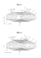
- FIG. 5 is a drawing illustrating a connection method in one phase belt in rotating machinery according to the fifth embodiment of the present invention.
- FIG. 6 is a drawing illustrating a connection method in one phase belt in rotating machinery according to the sixth embodiment of the present invention.
- FIG. 7 is a drawing illustrating a connection method in one phase belt in rotating machinery according to the seventh embodiment of the present invention.
- FIG. 8 is a drawing illustrating a connection method in one phase belt in rotating machinery according to the eighth embodiment of the present invention.
- FIG. 9 is a drawing illustrating a connection method in one phase belt in rotating machinery according to the ninth embodiment of the present invention.
- FIG. 10 is a drawing illustrating a connection method in one phase belt in rotating machinery according to the tenth embodiment of the present invention.
- FIG. 11 is a drawing illustrating a connection method in one phase belt in rotating machinery according to the eleventh embodiment of the present invention.
- FIG. 12 is a drawing illustrating a connection method in one phase belt in rotating machinery according to the twelfth embodiment of the present invention.
- FIG. 13 is a drawing illustrating a connection method in one phase belt in rotating machinery according to the thirteenth embodiment of the present invention.
- FIG. 14 is a drawing illustrating a connection method in one phase belt in rotating machinery according to the fourteenth embodiment of the present invention.
- FIG. 15 is an axial sectional view of the stator of rotating machinery according to an embodiment of the present invention.
- FIG. 16 is a connection diagram showing armature coils only in the U phase and terminals in a two-pole, two-parallel circuit configuration, obtained by developing the stator of the rotating machinery in FIG. 15 in the circumferential direction;
- FIG. 17 is a drawing illustrating a connection method in a phase belt in conventional rotating machinery (disclosed in U.S. Pat. No. 2,778,962);
- FIG. 18 is a drawing illustrating a connection method in a phase belt in conventional rotating machinery (disclosed in JP 5,193,557).
- FIG. 1 illustrates a connection method in one phase belt in rotating machinery according to the first embodiment of the present invention.
- rotating machinery includes a 2n-pole rotor 14 (see FIG. 15 , not shown in FIG. 1 ), 72n slots 5 , and three-phase armature windings 13 (where n denotes an integer not less than 1).
- Each of the slots 5 houses a top coil 12 on the inner radius side of each of the slots 5 and a bottom coil 3 on the outer radius side thereof.
- Each of the armature windings 13 is formed by connecting the top coil 12 and the bottom coil 3 and has 2n phase belts 6 per phase.
- Each of the phase belts 6 includes a first parallel winding 1 and a second parallel winding 2 .
- the top coil 12 and the bottom coil 3 are formed by arranging the first and second parallel windings 1 , 2 in a predefined order.
- first parallel winding 1 and the second parallel winding 2 are arranged in the order of the first, second, first, second, second, first, second, first, second, first, second, and first parallel windings in the top coil 12 ; and the first parallel winding 1 and the second parallel winding 2 are arranged in the order of the first, second, first, second, first, second, second, first, second, first, second, and first parallel windings in the bottom coil 3 connected to the top coil 12 .
- the number of jumper connections 8 per one phase belt 6 is only two on the non-connection side where terminals 7 are not present, reducing the number of the jumper connections 8 . Since the number of the jumper connections 8 is reduced, degradation in workability is suppressed and, as the result of the improvement of workability, a production cost can be reduced. Since the number of joints of the jumper connections 8 is reduced, reliability is enhanced in terms of the securement of insulation performance and fixation strength. Since the jumper connections 8 are used, a circulating current between circuits can be suppressed and the effect of preventing burnout of the windings due to excessive heating is obtained.
- FIG. 2 illustrates a connection method for one phase belt in rotating machinery according to the second embodiment of the present invention. With this method, the number of the jumper connections 8 can be reduced to two.
- the coil pitch on the terminal 7 side is changed and further the polarities of the parallel circuits are changed.
- the first parallel winding 1 and the second parallel winding 2 are arranged in the order of the first, second, first, second, first, second, second, first, second, first, second, and first parallel windings in the top coil 12 ; and the first parallel winding 1 and the second parallel winding 2 are arranged in the order of the first, second, first, second, first, second, second, first, second, and first parallel windings in the bottom coil 3 connected to the top coil 12 .
- Other configuration of the rotating machinery in this embodiment is the same as in the first embodiment.
- FIG. 3 illustrates a connection method for one phase belt in rotating machinery according to the third embodiment of the present invention.
- the first parallel winding 1 and the second parallel winding 2 are arranged in the order of the first, second, second, second, first, first, first, first, second, second, second, and first parallel windings in the top coil 12 and in the bottom coil 3 .
- Other configuration of the rotating machinery in this embodiment is the same as in the first embodiment.
- the number of the jumper connections 8 per one phase belt 6 is only three on the connection side.
- FIG. 4 illustrates a connection method for one phase belt in rotating machinery according to the fourth embodiment of the present invention. With this method, though the number of the jumper connections 8 is increased to four per one phase belt 6 , a circulating current can be more reduced.
- the first parallel winding 1 and the second parallel winding 2 are arranged in the order of the second, first, second, first, first, second, first, second, first, second, second, and first parallel windings in the top coil 12 ; and the first parallel winding 1 and the second parallel winding 2 are arranged in the order of the second, first, second, first, second, first, second, first, first, second, first, and second parallel windings in the bottom coil 3 connected to the top coil 12 .
- Other configuration of the rotating machinery in this embodiment is the same as in the first embodiment.
- the number of the jumper connections 8 per one phase belt 6 is only four, two on the connection side and two on the non-connection side.
- FIG. 5 illustrates a connection method for one phase belt in rotating machinery according to the fifth embodiment of the present invention.
- the first parallel winding 1 and the second parallel winding 2 are arranged in the order of the second, first, first, second, first, second, second, first, second, first, second, and first parallel windings in the top coil 12 ; and the first parallel winding 1 and the second parallel winding 2 are arranged in the order of the first, second, first, second, second, first, second, first, first, and second parallel windings in the bottom coil 3 connected to the top coil 12 .
- Other configuration of the rotating machinery in this embodiment is the same as in the first embodiment.
- the number of the jumper connections 8 per one phase belt 6 is only four, two on the connection side and two on the non-connection side.
- FIG. 6 illustrates a connection method for one phase belt in rotating machinery according to the sixth embodiment of the present invention.
- the coil pitch on the terminal 7 side is changed and further the polarities of the parallel circuits are changed as in the second embodiment.
- the first parallel winding 1 and the second parallel winding 2 are arranged in the order of the second, first, first, second, first, second, first, second, second, first, second, and first parallel windings in the top coil 12 ; and the first parallel winding 1 and the second parallel winding 2 are arranged in the order of the first, second, first, second, second, first, second, first, first, and second parallel windings in the bottom coil 3 connected to the top coil 12 .
- Other configuration of the rotating machinery in this embodiment is the same as in the first embodiment.
- the number of the jumper connections 8 per one phase belt 6 is only four, two on the connection side and two on the non-connection side.
- FIG. 7 illustrates a connection method for one phase belt in rotating machinery according to the seventh embodiment of the present invention.
- the coil pitch on the terminal 7 side is changed and further the polarities of the parallel circuits are changed as in the second and sixth embodiments.
- the first parallel winding 1 and the second parallel winding 2 are arranged in the order of the second, first, first, second, first, second, second, first, second, first, second, and first parallel windings in the top coil 12 ; and the first parallel winding 1 and the second parallel winding 2 are arranged in the order of the first, second, first, second, second, first, second, first, second, and first parallel windings in the bottom coil 3 connected to the top coil 12 .
- Other configuration of the rotating machinery in this embodiment is the same as in the first embodiment.
- the number of the jumper connections 8 per one phase belt 6 is only four, two on the connection side and two on the non-connection side.
- FIG. 8 illustrates a connection method for one phase belt in rotating machinery according to the eighth embodiment of the present invention.
- this method as in the fourth, fifth, sixth, and seventh embodiments, though the number of the jumper connections 8 is increased to four per one phase belt 6 , a circulating current can be more reduced.
- the coil pitch on the terminal 7 side is changed and further the polarities of the parallel circuits are changed as in the second, sixth, and seventh embodiments.
- the first parallel winding 1 and the second parallel winding 2 are arranged in the order of the second, first, second, first, first, second, first, second, second, and first parallel windings in the top coil 12 ; and the first parallel winding 1 and the second parallel winding 2 are arranged in the order of the first, second, first, second, first, second, first, second, first, first, and second parallel windings in the bottom coil 3 connected to the top coil 12 .
- Other configuration of the rotating machinery in this embodiment is the same as in the first embodiment.
- the number of the jumper connections 8 per one phase belt 6 is only four on the non-connection side.
- FIG. 9 illustrates a connection method for one phase belt in rotating machinery according to the ninth embodiment of the present invention. With this method, though the number of the jumper connections 8 is increased to five per one phase belt 6 , a circulating current can be more reduced.
- the first parallel winding 1 and the second parallel winding 2 are arranged in the order of the second, first, first, first, second, second, second, second, first, first, second, and first parallel windings in the top coil 12 ; and the first parallel winding 1 and the second parallel winding 2 are arranged in the order of the second, first, first, first, second, second, second, second, first, first, first, and second parallel windings in the bottom coil 3 connected to the top coil 12 .
- Other configuration of the rotating machinery in this embodiment is the same as in the first embodiment.
- the number of the jumper connections 8 per one phase belt 6 is five, three on the connection side and two on the non-connection side.
- FIG. 10 illustrates a connection method for one phase belt in rotating machinery according to the tenth embodiment of the present invention.
- the first parallel winding 1 and the second parallel winding 2 are arranged in the order of the first, second, second, first, first, second, second, first, first, second, second, and first parallel windings in the top coil 12 and in the bottom coil 3 .
- Other configuration of the rotating machinery in this embodiment is the same as in the first embodiment.
- the number of the jumper connections 8 per one phase belt 6 is five on the connection side.
- FIG. 11 illustrates a connection method for one phase belt in rotating machinery according to the eleventh embodiment of the present invention. With this method, though the number of the jumper connections 8 is increased to six per one phase belt 6 , a circulating current can be more reduced.
- the first parallel winding 1 and the second parallel winding 2 are arranged in the order of the second, first, first, second, second, first, first, second, first, second, second, and first parallel windings in the top coil 12 ; and the first parallel winding 1 and the second parallel winding 2 are arranged in the order of the first, second, second, first, second, first, first, second, second, first, first, and second parallel windings in the bottom coil 3 connected to the top coil 12 .
- Other configuration of the rotating machinery in this embodiment is the same as in the first embodiment.
- the number of the jumper connections 8 per one phase belt 6 is six on the connection side.
- FIG. 12 illustrates a connection method for one phase belt in rotating machinery according to the twelfth embodiment of the present invention.
- this method as in the eleventh embodiment, though the number of the jumper connections 8 is increased to six per one phase belt 6 , a circulating current can be more reduced.
- the first parallel winding 1 and the second parallel winding 2 are arranged in the order of the second, first, first, second, first, second, first, second, second, second, first, and first parallel windings in the top coil 12 ; and the first parallel winding 1 and the second parallel winding 2 are arranged in the order of the first, second, second, first, second, first, second, first, first, and second parallel windings in the bottom coil 3 connected to the top coil 12 .
- Other configuration of the rotating machinery in this embodiment is the same as in the first embodiment.
- the number of the jumper connections 8 per one phase belt 6 is six, three on the connection side and three on the non-connection side.
- FIG. 13 illustrates a connection method for one phase belt in rotating machinery according to the thirteenth embodiment of the present invention.
- the first parallel winding 1 and the second parallel winding 2 are arranged in the order of the second, first, first, second, first, second, first, second, first, second, second, and first parallel windings in the top coil 12 ; and the first parallel winding 1 and the second parallel winding 2 are arranged in the order of the first, second, second, first, second, first, first, first, second, and second parallel windings in the bottom coil 3 connected to the top coil 12 .
- Other configuration of the rotating machinery in this embodiment is the same as in the first embodiment.
- the number of the jumper connections 8 per one phase belt 6 is six, three on the connection side and three on the non-connection side.
- FIG. 14 illustrates a connection method for one phase belt in rotating machinery according to fourteenth embodiment of the present invention.
- this method as in the eleventh and twelfth embodiments, though the number of the jumper connections 8 is increased to six per one phase belt 6 , a circulating current can be more reduced.
- the first parallel winding 1 and the second parallel winding 2 are arranged in the order of the first, second, second, first, first, second, first, second, second, first, second, and first parallel windings in the top coil 12 ; and the first parallel winding 1 and the second parallel winding 2 are arranged in the order of the first, second, second, first, second, first, first, second, first, second, second, and first parallel windings in the bottom coil 3 connected to the top coil 12 .
- Other configuration of the rotating machinery in this embodiment is the same as in the first embodiment.
- the number of the jumper connections 8 per one phase belt 6 is six, two on the connection side and four on the non-connection side.
- the combination of the top coil 12 and the bottom coil 3 can be inverted in the wire connections described in the first to fourteenth embodiments.
- the first parallel winding 1 and the second parallel winding 2 can be arranged in the order of the first, second, first, second, first, second, second, first, second, first, second, and first parallel windings from the phase belt center 9 in the top coil 12 ; and the first parallel winding 1 and the second parallel winding 2 can be arranged in the order of the first, second, first, second, second, first, second, first, second, first, second, and first parallel windings in the bottom coil 3 connected to the top coil 12 . Even with this configuration, the same effects as in the first embodiment can be obtained.
- wire connections described in the first to fourteenth embodiments which are configured for one phase belt 6 in the embodiments, can be combined because there are six phase belts 6 in two-pole rotating machinery. In a case where the wire connections are combined, effects can be obtained depending on the combination.
- the wire connections described in the first to fourteenth embodiments are configurations in two-pole, 72-slot, and four-parallel circuit rotating machinery.
- “n” is an integer not less than 1
- the number of slots per phase and per pole is also 12 in 2n-pole, 72n-slot, and 4n-parallel circuit rotating machinery, to which the first to fourteenth embodiments are obviously applicable.
- the present invention is not limited to the above-mentioned embodiments and includes various modifications.
- the above embodiments are described in detail for better understanding of the present invention and the present invention does not necessarily require all the configuration elements mentioned above.
- Apart of the configuration of some embodiment can be substituted by a configuration element of any other embodiment and a configuration element of some embodiment can also be added to the configuration of another embodiment.
- a part of the configuration elements of the embodiments can be deleted, added with, or substituted by any other configuration element.
Landscapes
- Engineering & Computer Science (AREA)
- Power Engineering (AREA)
- Windings For Motors And Generators (AREA)
Abstract
Description
-
- 1 - - - first parallel winding
- 2 - - - second parallel winding
- 3 - - - bottom coil
- 4 - - - teeth
- 5 - - - slot
- 6 - - - phase belt
- 7 - - - terminal
- 8 - - - jumper connection
- 9 - - - phase belt center
- 11 - - - stator core
- 12 - - - top coil
- 13 - - - armature windings
- 14 - - - rotor
Claims (1)
Applications Claiming Priority (2)
| Application Number | Priority Date | Filing Date | Title |
|---|---|---|---|
| JP2013231090A JP6267933B2 (en) | 2013-11-07 | 2013-11-07 | Rotating electric machine |
| JP2013-231090 | 2013-11-07 |
Publications (2)
| Publication Number | Publication Date |
|---|---|
| US20150123508A1 US20150123508A1 (en) | 2015-05-07 |
| US10090722B2 true US10090722B2 (en) | 2018-10-02 |
Family
ID=51900175
Family Applications (1)
| Application Number | Title | Priority Date | Filing Date |
|---|---|---|---|
| US14/532,352 Active 2037-06-06 US10090722B2 (en) | 2013-11-07 | 2014-11-04 | Rotating machinery with three-phase armature windings and first and second parallel windings |
Country Status (3)
| Country | Link |
|---|---|
| US (1) | US10090722B2 (en) |
| EP (1) | EP2871755B1 (en) |
| JP (1) | JP6267933B2 (en) |
Cited By (2)
| Publication number | Priority date | Publication date | Assignee | Title |
|---|---|---|---|---|
| US11018542B2 (en) * | 2018-08-28 | 2021-05-25 | Mitsubishi Power, Ltd. | Rotating machinery with three-phase armature windings and first and second parallel windings |
| US12057743B2 (en) | 2020-07-16 | 2024-08-06 | Kabushiki Kaisha Toshiba | Abnormality detection system of rotary electrical machine |
Families Citing this family (3)
| Publication number | Priority date | Publication date | Assignee | Title |
|---|---|---|---|---|
| CN105305688B (en) * | 2015-11-01 | 2017-10-24 | 嘉兴学院 | Novel double-layer simplex lap winding low-vibration noise single phase series motor |
| JP6560606B2 (en) * | 2015-12-11 | 2019-08-14 | 三菱日立パワーシステムズ株式会社 | Rotating electric machine |
| WO2019021408A1 (en) * | 2017-07-27 | 2019-01-31 | 三菱電機株式会社 | Rorating electric machine |
Citations (7)
| Publication number | Priority date | Publication date | Assignee | Title |
|---|---|---|---|---|
| US2778962A (en) * | 1954-02-11 | 1957-01-22 | Gen Electric | Armature winding with four parallels per phase |
| GB858508A (en) | 1957-05-02 | 1961-01-11 | Vickers Electrical Co Ltd | Improvements relating to armature windings for dynamo-electric machines |
| GB858509A (en) | 1957-05-02 | 1961-01-11 | Vickers Electrical Co Ltd | Improvements relating to armature windings for dynamo-electric machines |
| FR1527835A (en) | 1967-02-22 | 1968-06-07 | Gen Electric | Nested winding for multi-phase rotating electrical machines |
| US3408517A (en) * | 1966-02-23 | 1968-10-29 | Gen Electric | Multiple circuit winding patterns for polyphase dynamoelectric machines |
| US20080238240A1 (en) * | 2007-03-29 | 2008-10-02 | Kazuhiko Takahashi | Rotary electric machine |
| EP2051350A2 (en) | 2007-10-16 | 2009-04-22 | Kabushiki Kaisha Toshiba | Winding scheme of an armature |
Family Cites Families (1)
| Publication number | Priority date | Publication date | Assignee | Title |
|---|---|---|---|---|
| JP5060325B2 (en) * | 2008-01-31 | 2012-10-31 | 株式会社東芝 | Armature winding of rotating electric machine |
-
2013
- 2013-11-07 JP JP2013231090A patent/JP6267933B2/en active Active
-
2014
- 2014-11-04 US US14/532,352 patent/US10090722B2/en active Active
- 2014-11-07 EP EP14192241.9A patent/EP2871755B1/en active Active
Patent Citations (9)
| Publication number | Priority date | Publication date | Assignee | Title |
|---|---|---|---|---|
| US2778962A (en) * | 1954-02-11 | 1957-01-22 | Gen Electric | Armature winding with four parallels per phase |
| GB858508A (en) | 1957-05-02 | 1961-01-11 | Vickers Electrical Co Ltd | Improvements relating to armature windings for dynamo-electric machines |
| GB858509A (en) | 1957-05-02 | 1961-01-11 | Vickers Electrical Co Ltd | Improvements relating to armature windings for dynamo-electric machines |
| US3408517A (en) * | 1966-02-23 | 1968-10-29 | Gen Electric | Multiple circuit winding patterns for polyphase dynamoelectric machines |
| FR1527835A (en) | 1967-02-22 | 1968-06-07 | Gen Electric | Nested winding for multi-phase rotating electrical machines |
| US20080238240A1 (en) * | 2007-03-29 | 2008-10-02 | Kazuhiko Takahashi | Rotary electric machine |
| EP2051350A2 (en) | 2007-10-16 | 2009-04-22 | Kabushiki Kaisha Toshiba | Winding scheme of an armature |
| US7834508B2 (en) | 2007-10-16 | 2010-11-16 | Kabushiki Kaisha Toshiba | Slot positions for a three-phase two-pole armature winding with a seventy-two slot armature core |
| JP5193557B2 (en) | 2007-10-16 | 2013-05-08 | 株式会社東芝 | Armature |
Non-Patent Citations (1)
| Title |
|---|
| Extended European Search Report received in corresponding European Application No. 14192241.9 dated Apr. 14, 2015. |
Cited By (2)
| Publication number | Priority date | Publication date | Assignee | Title |
|---|---|---|---|---|
| US11018542B2 (en) * | 2018-08-28 | 2021-05-25 | Mitsubishi Power, Ltd. | Rotating machinery with three-phase armature windings and first and second parallel windings |
| US12057743B2 (en) | 2020-07-16 | 2024-08-06 | Kabushiki Kaisha Toshiba | Abnormality detection system of rotary electrical machine |
Also Published As
| Publication number | Publication date |
|---|---|
| EP2871755B1 (en) | 2019-09-11 |
| JP2015091205A (en) | 2015-05-11 |
| EP2871755A1 (en) | 2015-05-13 |
| JP6267933B2 (en) | 2018-01-24 |
| US20150123508A1 (en) | 2015-05-07 |
Similar Documents
| Publication | Publication Date | Title |
|---|---|---|
| US9866083B2 (en) | Stator for rotating electric machine | |
| US11509180B2 (en) | Stator | |
| US9240707B2 (en) | Rotary electric machine | |
| JP5193557B2 (en) | Armature | |
| US9444296B2 (en) | Stator winding of electrical rotating machine | |
| EP3217516B1 (en) | Rotating electrical machine | |
| US10090722B2 (en) | Rotating machinery with three-phase armature windings and first and second parallel windings | |
| KR101721462B1 (en) | Wind power generator as well as stator core and stator core module thereof | |
| US20190013710A1 (en) | Rotary Electric Machine | |
| US20170110923A1 (en) | Electric machine | |
| US11114913B2 (en) | Rotating electric machine | |
| US10193406B2 (en) | Rotating machinery | |
| CN110867994B (en) | Rotary motor | |
| JP2008099502A (en) | Rotating electric machine | |
| US11374455B2 (en) | Rotary electric machine | |
| JP7638065B2 (en) | Rotating Electric Machine | |
| JP5991702B2 (en) | AC generator | |
| US9231447B2 (en) | Stator winding of an electric generator | |
| CN102195424A (en) | Power generator for outputting from motional electromotive force to induced electromotive force |
Legal Events
| Date | Code | Title | Description |
|---|---|---|---|
| AS | Assignment |
Owner name: MITSUBISHI HITACHI POWER SYSTEMS, LTD., JAPAN Free format text: ASSIGNMENT OF ASSIGNORS INTEREST;ASSIGNORS:YOSHIDA, JUN;TAKAHASHI, KAZUHIKO;YANAGITA, NORIHITO;AND OTHERS;SIGNING DATES FROM 20141027 TO 20141029;REEL/FRAME:034099/0038 |
|
| STCF | Information on status: patent grant |
Free format text: PATENTED CASE |
|
| AS | Assignment |
Owner name: MITSUBISHI POWER, LTD., JAPAN Free format text: CHANGE OF NAME;ASSIGNOR:MITSUBISHI HITACHI POWER SYSTEMS, LTD.;REEL/FRAME:054975/0438 Effective date: 20200901 |
|
| MAFP | Maintenance fee payment |
Free format text: PAYMENT OF MAINTENANCE FEE, 4TH YEAR, LARGE ENTITY (ORIGINAL EVENT CODE: M1551); ENTITY STATUS OF PATENT OWNER: LARGE ENTITY Year of fee payment: 4 |
|
| AS | Assignment |
Owner name: MITSUBISHI POWER, LTD., JAPAN Free format text: CORRECTIVE ASSIGNMENT TO CORRECT THE REMOVING PATENT APPLICATION NUMBER 11921683 PREVIOUSLY RECORDED AT REEL: 054975 FRAME: 0438. ASSIGNOR(S) HEREBY CONFIRMS THE ASSIGNMENT;ASSIGNOR:MITSUBISHI HITACHI POWER SYSTEMS, LTD.;REEL/FRAME:063787/0867 Effective date: 20200901 |
|
| AS | Assignment |
Owner name: MITSUBISHI HEAVY INDUSTRIES, LTD., JAPAN Free format text: NUNC PRO TUNC ASSIGNMENT;ASSIGNOR:MITSUBISHI POWER, LTD.;REEL/FRAME:064854/0880 Effective date: 20230904 |
|
| AS | Assignment |
Owner name: MITSUBISHI GENERATOR CO., LTD., JAPAN Free format text: NUNC PRO TUNC ASSIGNMENT;ASSIGNOR:MITSUBISHI HEAVY INDUSTRIES, LTD.;REEL/FRAME:069438/0941 Effective date: 20241009 |
|
| MAFP | Maintenance fee payment |
Free format text: PAYMENT OF MAINTENANCE FEE, 8TH YEAR, LARGE ENTITY (ORIGINAL EVENT CODE: M1552); ENTITY STATUS OF PATENT OWNER: LARGE ENTITY Year of fee payment: 8 |