US10090691B2 - Power generation system of renewable-energy-based electric power generator and DC power source combiner provided with reverse current prevention device capable of preventing power loss in power generation system - Google Patents
Power generation system of renewable-energy-based electric power generator and DC power source combiner provided with reverse current prevention device capable of preventing power loss in power generation system Download PDFInfo
- Publication number
- US10090691B2 US10090691B2 US15/111,613 US201415111613A US10090691B2 US 10090691 B2 US10090691 B2 US 10090691B2 US 201415111613 A US201415111613 A US 201415111613A US 10090691 B2 US10090691 B2 US 10090691B2
- Authority
- US
- United States
- Prior art keywords
- power
- voltage
- electric power
- output
- current
- Prior art date
- Legal status (The legal status is an assumption and is not a legal conclusion. Google has not performed a legal analysis and makes no representation as to the accuracy of the status listed.)
- Active, expires
Links
Images




Classifications
-
- H—ELECTRICITY
- H02—GENERATION; CONVERSION OR DISTRIBUTION OF ELECTRIC POWER
- H02J—ELECTRIC POWER NETWORKS; CIRCUIT ARRANGEMENTS OR SYSTEMS FOR SUPPLYING OR DISTRIBUTING ELECTRIC POWER; SYSTEMS FOR STORING ELECTRIC ENERGY
- H02J3/00—Circuit arrangements for AC mains or AC distribution networks
- H02J3/38—Arrangements for feeding a single network from two or more generators or sources in parallel; Arrangements for feeding already energised networks from additional generators or sources in parallel
- H02J3/46—Controlling the sharing of generated power between the generators, sources or networks
-
- H02J7/0034—
-
- H—ELECTRICITY
- H02—GENERATION; CONVERSION OR DISTRIBUTION OF ELECTRIC POWER
- H02J—ELECTRIC POWER NETWORKS; CIRCUIT ARRANGEMENTS OR SYSTEMS FOR SUPPLYING OR DISTRIBUTING ELECTRIC POWER; SYSTEMS FOR STORING ELECTRIC ENERGY
- H02J1/00—Circuit arrangements for DC mains or DC distribution networks
- H02J1/10—Parallel operation of DC sources
- H02J1/108—Parallel operation of DC sources having arrangements for blocking reverse current flow, e.g. using diodes
-
- H—ELECTRICITY
- H02—GENERATION; CONVERSION OR DISTRIBUTION OF ELECTRIC POWER
- H02J—ELECTRIC POWER NETWORKS; CIRCUIT ARRANGEMENTS OR SYSTEMS FOR SUPPLYING OR DISTRIBUTING ELECTRIC POWER; SYSTEMS FOR STORING ELECTRIC ENERGY
- H02J3/00—Circuit arrangements for AC mains or AC distribution networks
- H02J3/38—Arrangements for feeding a single network from two or more generators or sources in parallel; Arrangements for feeding already energised networks from additional generators or sources in parallel
-
- H—ELECTRICITY
- H02—GENERATION; CONVERSION OR DISTRIBUTION OF ELECTRIC POWER
- H02J—ELECTRIC POWER NETWORKS; CIRCUIT ARRANGEMENTS OR SYSTEMS FOR SUPPLYING OR DISTRIBUTING ELECTRIC POWER; SYSTEMS FOR STORING ELECTRIC ENERGY
- H02J3/00—Circuit arrangements for AC mains or AC distribution networks
- H02J3/38—Arrangements for feeding a single network from two or more generators or sources in parallel; Arrangements for feeding already energised networks from additional generators or sources in parallel
- H02J3/381—Dispersed generators
-
- H02J3/383—
-
- H02J3/385—
-
- H—ELECTRICITY
- H02—GENERATION; CONVERSION OR DISTRIBUTION OF ELECTRIC POWER
- H02J—ELECTRIC POWER NETWORKS; CIRCUIT ARRANGEMENTS OR SYSTEMS FOR SUPPLYING OR DISTRIBUTING ELECTRIC POWER; SYSTEMS FOR STORING ELECTRIC ENERGY
- H02J3/00—Circuit arrangements for AC mains or AC distribution networks
- H02J3/38—Arrangements for feeding a single network from two or more generators or sources in parallel; Arrangements for feeding already energised networks from additional generators or sources in parallel
- H02J3/46—Controlling the sharing of generated power between the generators, sources or networks
- H02J3/50—Controlling the sharing of reactive power
-
- H—ELECTRICITY
- H02—GENERATION; CONVERSION OR DISTRIBUTION OF ELECTRIC POWER
- H02J—ELECTRIC POWER NETWORKS; CIRCUIT ARRANGEMENTS OR SYSTEMS FOR SUPPLYING OR DISTRIBUTING ELECTRIC POWER; SYSTEMS FOR STORING ELECTRIC ENERGY
- H02J7/00—Circuit arrangements for charging or discharging batteries or for supplying loads from batteries
- H02J7/60—Circuit arrangements for charging or discharging batteries or for supplying loads from batteries including safety or protection arrangements
- H02J7/68—Circuit arrangements for charging or discharging batteries or for supplying loads from batteries including safety or protection arrangements using circuits for correcting or protecting against reverse-polarity
-
- H—ELECTRICITY
- H02—GENERATION; CONVERSION OR DISTRIBUTION OF ELECTRIC POWER
- H02J—ELECTRIC POWER NETWORKS; CIRCUIT ARRANGEMENTS OR SYSTEMS FOR SUPPLYING OR DISTRIBUTING ELECTRIC POWER; SYSTEMS FOR STORING ELECTRIC ENERGY
- H02J2101/00—Supply or distribution of decentralised, dispersed or local electric power generation
- H02J2101/20—Dispersed power generation using renewable energy sources
- H02J2101/22—Solar energy
- H02J2101/24—Photovoltaics
- H02J2101/25—Photovoltaics involving maximum power point tracking control for photovoltaic sources
-
- Y—GENERAL TAGGING OF NEW TECHNOLOGICAL DEVELOPMENTS; GENERAL TAGGING OF CROSS-SECTIONAL TECHNOLOGIES SPANNING OVER SEVERAL SECTIONS OF THE IPC; TECHNICAL SUBJECTS COVERED BY FORMER USPC CROSS-REFERENCE ART COLLECTIONS [XRACs] AND DIGESTS
- Y02—TECHNOLOGIES OR APPLICATIONS FOR MITIGATION OR ADAPTATION AGAINST CLIMATE CHANGE
- Y02E—REDUCTION OF GREENHOUSE GAS [GHG] EMISSIONS, RELATED TO ENERGY GENERATION, TRANSMISSION OR DISTRIBUTION
- Y02E10/00—Energy generation through renewable energy sources
- Y02E10/50—Photovoltaic [PV] energy
- Y02E10/56—Power conversion systems, e.g. maximum power point trackers
-
- Y02E10/58—
Definitions
- the present invention relates to a power generation system having a renewable-energy-based electric power generator and a DC power source combiner provided with a reverse current prevention device and used in the power generation system, and more particularly, to a DC power source combiner provided with a reverse current prevention device capable of preventing a power loss, by which its output is stabilized at all times, and maximum power generation is achieved at the corresponding time point by efficiently using the amount of sunlight that changes depending on an environment such as a climate by combining different types of power sources in order to cope with a variation in the electric power, for example, in a sunlight photovoltaic power generation system (for example, the generated electric power increases under high brightness of sunlight, but it decreases in the dark).
- a sunlight photovoltaic power generation system for example, the generated electric power increases under high brightness of sunlight, but it decreases in the dark.
- a power output of an electric power generator based on renewable energy such as sunlight or wind is still unstable.
- renewable energy such as sunlight or wind
- its output state remarkably varies depending on an environmental condition. Therefore, it is desirable to stabilize the output power in the future.
- the output power varies depending on a current-voltage condition at the time of power output operation. Therefore, it is indispensable to perform control for outputting the electric power under an optimum condition.
- the output current is maximized to 5.29 A (refer to a point A in FIG. 3 ).
- the voltage becomes zero (0 V). Therefore, the output power becomes zero (0 W).
- the output voltage When the output voltage is at 18.14 V, the output current becomes 4.97 A (refer to a point P in FIG. 2 ). In this case, a maximum power of, approximately, 90 W can be output (maximum power point). Even in a lower or higher voltage, the output power is reduced. In order to output the maximum power, for example, a so-called maximum power point tracking (MPPT) technique has been applied to a lot of power conditioners (refer to FIG. 4 ).
- MPPT maximum power point tracking
- a so-called reverse current prevention circuit (a circuit for preventing a reverse current flow, such as a reverse current prevention diode) or a DC converter (such as a PWM chopper circuit) used to supply power to a DC load with a higher priority from a DC power source side may be installed solely or in combination.
- the current may flow between a plurality of power sources, and this may generate a failure.
- the output voltages V 1 and V 2 of the DC converters 30 and 31 have a relationship of “V 1 >V 2 ,” and a load resistance is high (for example, if no load is connected), the current may flow to the DC converter 31 side as indicated by the arrow 32 , and this may generate a failure (refer to FIG. 8 ).
- the reverse current is blocked by providing reverse current prevention circuits 33 (for example, reverse current prevention diodes) as illustrated in FIG. 9 .
- reverse current prevention circuits 33 for example, reverse current prevention diodes
- an electric power loss is generated by providing the reverse current prevention circuit 33 described above when the electric current flows through the reverse current prevention circuit 33 .
- a reverse current prevention diode is employed in the reverse current prevention circuit 33 , for example, an electric power loss of 0.7 W may be generated for an electric current of 1 A due to a forward bias voltage of, approximately, 0.7 V in a typical diode.
- Patent Literature 1 Japanese Patent Application Publication No. 2011-181055
- the present invention has been made to address the aforementioned problems of the related art and improve the techniques of the related art through diligent efforts of the inventors.
- the invention provides a power generation system capable of directly using electric power generated by an electric power generator from renewable energy without voltage conversion or current conversion to prevent a loss in the electric power conversion of the electric power generator, outputting the electric power under a condition (voltage and current) where the maximum energy can be output from the electric power generator, stably outputting the electric power by combining other power sources, setting the electric power from the electric power generator with a highest priority ceaselessly while supplying only a deficiency from other power sources, that is, selecting a solar cell panel as the electric power generator while setting other power sources as a commercial power source.
- the invention provides a DC power source combiner 29 provided with a reverse current prevention device without a power loss, capable of preventing a reverse current while the reverse current prevention circuits 33 are not provided in the DC converter 30 or 31 to remove or remarkably reduce a power loss that may be generated by the reverse current prevention circuit 33 (such as a reverse current prevention diode).
- a power generation system capable of stably outputting electric power, from an electric power generator configured to generate electric power from renewable energy of which generable electric power varies depending on a change of an environmental condition, to a load side at a predetermined power amount and efficiently outputting electric power by using renewable energy without wasting regardless of a change of an environmental condition
- the power generation system including: at least an electric power generator configured to generate electric power from renewable energy of which generable electric power varies depending on a change of an environmental condition; and a maximum power amount detection control unit configured to perform control such that a maximum power point at which a power amount generated by the electric power generator from renewable energy reaches a maximum output power amount at a predetermined output time point regardless of a change of an environmental condition is detected at any time, voltage and current values at the maximum power point are detected at any time, and the generated power at the detected values is output, wherein, when the voltage value at the maximum power point detected by the maximum power amount detection control unit is lower than a voltage value of a predetermined
- a DC power source combiner provided with a reverse current prevention device and configured to combine electric power from a plurality of DC power sources and output the combined electric power to a DC load without a loss
- each of the plurality of DC power sources has a DC converter capable of preventing a reverse current
- the DC converter has a switch control circuit configured to set an electric power output to the DC load side to ON or OFF in the DC converter, a generated voltage value generated in the DC converter is compared with an output voltage value output to the DC load side, and the ON/OFF control of the switch control circuit is performed on the basis of a result of the comparison so that the switch control circuit serves as the reverse current prevention circuit.
- DC power source combiner which DC power source is used to supply electric power out of a combination of electric power from the plurality of DC power sources is determined on a priority basis.
- the electric power generated from the electric power generator according to the present invention is directly used without performing voltage conversion or current conversion. Therefore, there is no loss in electric power conversion of the electric power generator.
- a solar cell panel may be selected as the electric power generator, and other power sources may be selected as a commercial power source. In this case, it is possible to reduce a consumption of the electric power from the commercial power sources as much as the electric power generated from the solar cell panel.
- a DC power source combiner 29 provided with a reverse current prevention device capable of preventing a reverse current without providing the reverse current prevention circuits 33 in the DC converters 30 and 31 , and capable of removing or remarkably reducing a power loss that may be generated by the reverse current prevention circuit 33 (such as a reverse current prevention diode).
- FIG. 1 is a block diagram schematically illustrating a configuration of a power generation system according to the present invention
- FIG. 2 is a graph (1) illustrating a current-voltage relationship caused by an electric power generator
- FIG. 3 is a graph (2) illustrating a current-voltage relationship caused by the electric power generator
- FIG. 4 is a graph illustrating a power-voltage relationship caused by the electric power generator
- FIG. 5 is a block diagram schematically illustrating a DC converter according to the present invention.
- FIG. 6 is a block diagram schematically illustrating the entire system according to the present invention.
- FIG. 7 is a flowchart illustrating operations according to the present invention.
- FIG. 8 is a block diagram (1) schematically illustrating a system of the related art
- FIG. 9 is a block diagram (2) schematically illustrating a system of the related art.
- FIG. 10 is a block diagram schematically illustrating another embodiment according to the present invention.
- the reference numeral “ 1 ” denotes a power generation system according to the present invention.
- the power generation system 1 according to the present invention is a power generation system having a renewable-energy-based electric power generator 2 of which generated power varies depending on a change of an environmental condition, by which the electric power generated from the electric power generator 2 can be stably output to a load 3 side at a predetermined power amount, and the renewable energy can be used without wasting regardless of a change of an environmental condition to efficiently output the electric power.
- This power generation system 1 has at least one renewable-energy-based electric power generator 2 of which generated power varies depending on a change of an environmental condition.
- a plurality of electric power generators 2 may also be connected in series.
- the reference numeral “ 4 ” denotes a maximum power amount detection control unit generally embodied in a computer device and the like.
- the maximum power amount detection control unit 4 computes and detects, at any time, a maximum power point representing a maximum output power amount at a predetermined time point, in which the electric power amount generated by the electric power generator 2 can be output regardless of a change of an environmental condition.
- FIG. 4 is a diagram illustrating the maximum power point. In FIG. 4 , the maximum power point is indicated by the point P.
- the voltage and current values at this maximum power point that is, the voltage and current values at the maximum power point that varies depending on a change of an environmental condition from time to time are detected continuously, and control is performed such that the generated power at the detected values can be output.
- the reference numeral “ 5 ” denotes a variable voltage power source
- the reference numeral “ 6 ” denotes a constant voltage power source
- the electric power generator 2 is a solar cell panel (having an open circuit voltage of 22.59 V, a short-circuit current of 5.29 A, a maximum output operation voltage of 18.14 V, and a maximum output operation current of 4.97 A), and the output voltage VC of the constant voltage power source 6 is set to 25 V, the operation is performed as follows.
- the voltage is not reduced to the output voltage VC or the lower. For this reason, the voltage of the solar cell panel is maintained at 18.14 V, and the current IG of the solar cell panel at this time is 5.29 A, so that the maximum power point operation is achieved.
- the voltage VC of the constant voltage power source 6 is set by a user in advance depending on a use purpose, an environment, and the like.
- the voltage may be adjusted as follows:
- the electric power generator 2 is operated at the maximum power point. At this time, out of the output current, a deficiency of the current of the electric power generator 2 is supplemented by the current I from the constant voltage power source 5 .
- the maximum power point may be determined on the basis of a characteristic table.
- a hill-climbing method known as one of the typical MPPT methods may be employed.
- the voltage V may be adjusted to maximize a value of “VG ⁇ IG.”
- the constant voltage power source is not necessary.
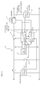
- FIG. 5 is a block diagram schematically illustrating an embodiment of the present invention.
- the reference numeral “ 1 ” denotes a DC converter.
- an output voltage control circuit 2 for controlling the output voltage is provided.
- the output voltage control circuit 12 controls the voltage of the output side of the first DC power source 14 or the second DC power source 15 , for example, by setting the switch circuit 13 to ON or OFF.
- the ON/OFF control of the switch circuit 13 is performed using a reverse current control ON/OFF circuit 16 described below to control the voltage of the output side of the first or second DC power source 14 or 15 .
- an ON/OFF function for preventing a reverse current is added to an existing circuit used to control the output voltage of the first or second DC power source 14 or 15 .
- a generated voltage generated in the output voltage control circuit 12 and the output voltage are compared using a voltage comparator circuit 18 , and the ON/OFF control of the switch circuit 13 is performed on the basis of the comparison result in order to prevent a reverse current, that is, such that the direction of the arrow 17 in FIG. 5 is not reversed.
- a reverse current that is, such that the direction of the arrow 17 in FIG. 5 is not reversed.
- the direction of this current may be monitored generally by checking a value of a detection system 19 such as an amperemeter.
- this method is also employed in the reverse current prevention control. That is, a function of the reverse current prevention circuit is implemented by using the switch circuit 13 and the circuit that switches ON/OFF existing in the DC converter 100 such that the current does not flow reversely.
- the switch circuit 13 is a semiconductor switch (such as a transistor, a field effect transistor (FET), and an insulated-gate bipolar transistor (IGBT)).
- FET field effect transistor
- IGBT insulated-gate bipolar transistor
- PWM pulse width modulation
- the reference numeral “ 19 ” denotes a current detector (such as a shunt resistor or a current transformer). If the current detected by the current detector is reversed (opposite to the arrow direction 17 in FIG. 5 ), or if the voltage detected by the voltmeter 20 is compared using the voltage comparator circuit 18 , and the output voltage VO is higher than the generated voltage Vs (VO>Vs), the switch circuit 13 is forcibly set to OFF. If the generated voltage Vs is higher than the output voltage VO, the ON/OFF control of the switch circuit 13 is returned to a normal control mode.
- a current detector such as a shunt resistor or a current transformer
- a normal control mode of the DC converter 10 that is, the control of the output voltage may be performed using any configuration.
- the switching period of the switch circuits 13 - 1 and 13 - 2 may be controlled using a so-called PWM technique to a constant voltage in order to maintain the output voltage VO at a constant level (note that a normal control mode of the DC converter 10 may be performed for the switch circuit 13 - 2 even when the switch circuit 13 - 1 is cut off).
- a voltage range of the DC load 21 is set to 100 to 150 V
- a target voltage of the DC converter 10 of the first DC power source 14 (referred to as a generated voltage “VS 1 ”) is set to 140 V
- a target voltage of the DC converter 10 of the second DC power source 5 (referred to as a generated voltage “VS 2 ”) is set to 120 V
- the switch circuit 13 is set in ON when the load voltage is lower than a generated voltage in any DC converter 10 . Therefore, the voltage of the load is equal to or higher than 120 V.
- the electric power of the load is sufficiently supplied from the first DC power source 14 , the electric power is supplied from the first DC power source 14 , and the load voltage becomes 140 V.
- the load voltage (140V) is higher than the generated voltage VS 2 (120 V)
- the switch circuit 13 of the DC converter 10 of the second DC power source 15 is set to OFF. Therefore, the electric power is supplied only from the first DC power source 14 .
- the load voltage is lowered.
- the load voltage becomes lower than the generated voltage VS 2 (120V). Therefore, the switch circuit 13 of the DC converter 10 of the second DC power source 15 is set to ON, so that the electric power is supplied to the load from both the first and second DC power sources 14 and 15 .
- Distribution of the electric power to the first and second DC power sources 14 and 15 is determined on the basis of a power capacity and a voltage setting. While a voltage of 0 to 140 V is output to the first DC power source 14 , a voltage of 0 to 120 V is set for the second DC power source 15 . Therefore, an equilibrium state is achieved in the vicinity of 120 V so that a deficiency of the first DC power source 14 is supplemented from the second DC power source 15 .
- a high voltage for example, 140 V
- a low voltage for example, 120 V
- the electric power is supplied from the second DC power source 15 . If the electric power of the load is not sufficiently supplied only from the second DC power source 15 , the electric power is supplied from both the first and second DC power sources 14 and 15 .
- Similar processing may be performed for a case where three or more DC power sources are provided, and a plurality of power sources may be selected on the basis of the voltage setting.
- a voltage of the DC converter 30 is set to 120 V
- a voltage of the DC converter 31 is set to 110 V
- a voltage of the DC converter 34 is set to 100 V. If the electric power is supplied from a combination of a first power source and a DC converter 30 of FIG. 10 , which has nearly no load, the output voltage becomes 120 V, and no electric current flows from the DC converters 31 and 34 .
- the output voltage is lowered.
- the electric power is also supplied from the DC converter 31 .
- the output voltage is set to 110 V.
- the load is much larger, and the electric power is not sufficiently supplied from the first and second power sources, the output voltage is lowered.
- the electric power is supplied from the third power source. In this manner, it is possible to determine a priority for supplying the electric power by setting the voltages even for three power sources.
- the priority may be selected, for example, such that the highest voltage is set for the lowest cost power source, and the secondly highest voltage is set for the secondly lowest cost power source, and the lowest voltage is set for the highest cost power source.
- an environment-based power source setting may be possible by setting the higher voltage to the smaller environmental load.
- the priority may also be set on the basis of the suppliable power amount.
- Such settings may similarly apply to four or more power sources.
Landscapes
- Engineering & Computer Science (AREA)
- Power Engineering (AREA)
- Dc-Dc Converters (AREA)
- Control Of Electrical Variables (AREA)
- Direct Current Feeding And Distribution (AREA)
Abstract
Description
V=VO−VP (if IO≥maximum output operation current),
and
V=VO−VG (if IO<maximum output operation current).
-
- (1) V=6.86 V (if the output current is set to “IO≥5.29 A”), and
- (2) V=VO−VP (if the output current is set to “IO<5.29 A”).
-
- If the condition (2) is satisfied, the current of the load 3 can be supplied with the current of the
electric power generator 2.
- If the condition (2) is satisfied, the current of the load 3 can be supplied with the current of the
-
- As the variable
voltage power source 4 or the constant voltage power source 5, the DC power may be obtained by converting commercial AC power.
Embodiment 2
- As the variable
-
- The output
voltage control circuit 12 is a circuit for generating a signal used in the ON/OFF control of the switch circuit 13 and controls the electric power flowing to the output on the basis of a pulse width or a pulse interval.
- The output
-
- It is assumed that a reverse current flow directed oppositely to the
arrow 17 inFIG. 5 is generated due to any voltage variation. - In this case, in the DC converter 100, a reverse current is detected by the
current detector 19. As the reverse current is detected, the switch circuit 13 is cut off, and the current becomes zero. Therefore, a reverse current can be prevented by holding this state.
- It is assumed that a reverse current flow directed oppositely to the
-
- Note that, while the present invention has been described as a voltage boosting circuit in the aforementioned embodiment, a voltage dropping circuit may also be employed. By setting the target voltage as described above, it is possible to select a power source in the similar way.
Claims (3)
Applications Claiming Priority (1)
| Application Number | Priority Date | Filing Date | Title |
|---|---|---|---|
| PCT/JP2014/000162 WO2015107563A1 (en) | 2014-01-15 | 2014-01-15 | Power generation system for power generation device harnessing natural energy, and dc power supply combination device having reverse-current blocking device and no power loss used in said power generation system |
Publications (2)
| Publication Number | Publication Date |
|---|---|
| US20160344212A1 US20160344212A1 (en) | 2016-11-24 |
| US10090691B2 true US10090691B2 (en) | 2018-10-02 |
Family
ID=53542495
Family Applications (1)
| Application Number | Title | Priority Date | Filing Date |
|---|---|---|---|
| US15/111,613 Active 2034-05-14 US10090691B2 (en) | 2014-01-15 | 2014-01-15 | Power generation system of renewable-energy-based electric power generator and DC power source combiner provided with reverse current prevention device capable of preventing power loss in power generation system |
Country Status (4)
| Country | Link |
|---|---|
| US (1) | US10090691B2 (en) |
| CN (1) | CN105917543A (en) |
| DE (1) | DE112014006170T5 (en) |
| WO (1) | WO2015107563A1 (en) |
Families Citing this family (9)
| Publication number | Priority date | Publication date | Assignee | Title |
|---|---|---|---|---|
| US20150221799A1 (en) * | 2014-01-29 | 2015-08-06 | Nate D. Hawthorn | Transformerless Photovoltaic Solar Heating System |
| JP6662035B2 (en) * | 2015-12-25 | 2020-03-11 | 富士電機株式会社 | Control device |
| DE102016125219B4 (en) * | 2016-12-21 | 2019-01-17 | Sma Solar Technology Ag | Circuit for limiting voltage in a photovoltaic field, photovoltaic field and voltage limiting method |
| US11374402B2 (en) * | 2017-03-24 | 2022-06-28 | Ford Global Technologies, Llc | Protection circuit for oscilloscope measurement channel |
| JP7307645B2 (en) * | 2019-09-26 | 2023-07-12 | 京セラ株式会社 | Power management system and power management method |
| US11081887B1 (en) * | 2020-05-04 | 2021-08-03 | 8Me Nova, Llc | Systems and methods utilizing AC overbuilt renewable electric generation resource and charge storage device providing desired capacity factor |
| US11916383B2 (en) | 2020-05-04 | 2024-02-27 | 8Me Nova, Llc | Implementing power delivery transaction for potential electrical output of integrated renewable energy source and energy storage system facility |
| US11621776B2 (en) * | 2020-07-29 | 2023-04-04 | Corning Research & Development Corporation | Systems for low power distribution in a power distribution network |
| CN113629731A (en) * | 2021-08-23 | 2021-11-09 | 华电重工股份有限公司 | Wind-solar combined stable water electrolysis hydrogen production system |
Citations (9)
| Publication number | Priority date | Publication date | Assignee | Title |
|---|---|---|---|---|
| JPH0736556A (en) | 1993-06-28 | 1995-02-07 | Sanyo Electric Co Ltd | Cooling method for electrical equipment powered by solar cells |
| JPH1084630A (en) | 1996-09-10 | 1998-03-31 | N T T Facilities:Kk | DC power supply device combined with solar cell and control method thereof |
| JP2000023365A (en) | 1998-07-07 | 2000-01-21 | Toshiba Corp | Power generation system |
| JP2001275348A (en) | 2000-03-29 | 2001-10-05 | Hitachi Ltd | DC power supply, control circuit therefor, and power supply semiconductor integrated circuit device |
| JP3149024U (en) | 2008-10-01 | 2009-03-12 | 實 村野 | Commercial power injection type solar cell DC interconnection system |
| JP2011036086A (en) | 2009-08-05 | 2011-02-17 | Honda Motor Co Ltd | Dc-dc converter and power feeding system including the same |
| JP2011172454A (en) | 2010-02-22 | 2011-09-01 | Kddi Corp | Rectifier control system for photovoltaic power generation system |
| JP2012075224A (en) | 2010-09-28 | 2012-04-12 | Shikoku Res Inst Inc | Power storage system for renewable energy |
| JP2013158192A (en) | 2012-01-31 | 2013-08-15 | Minoru Murano | Proper control method of power generation output |
Family Cites Families (2)
| Publication number | Priority date | Publication date | Assignee | Title |
|---|---|---|---|---|
| CN101777777A (en) * | 2009-01-13 | 2010-07-14 | 周德佳 | Direct current voltage regulation-based maximum power point tracking method for photovoltaic array with stable charging circuit |
| CN103475024A (en) * | 2013-09-11 | 2013-12-25 | 国网山东省电力公司聊城供电公司 | Electric energy quality serial connection compensation control method and system based on solar photovoltaic power generation |
-
2014
- 2014-01-15 DE DE112014006170.0T patent/DE112014006170T5/en not_active Ceased
- 2014-01-15 CN CN201480073063.8A patent/CN105917543A/en active Pending
- 2014-01-15 WO PCT/JP2014/000162 patent/WO2015107563A1/en not_active Ceased
- 2014-01-15 US US15/111,613 patent/US10090691B2/en active Active
Patent Citations (9)
| Publication number | Priority date | Publication date | Assignee | Title |
|---|---|---|---|---|
| JPH0736556A (en) | 1993-06-28 | 1995-02-07 | Sanyo Electric Co Ltd | Cooling method for electrical equipment powered by solar cells |
| JPH1084630A (en) | 1996-09-10 | 1998-03-31 | N T T Facilities:Kk | DC power supply device combined with solar cell and control method thereof |
| JP2000023365A (en) | 1998-07-07 | 2000-01-21 | Toshiba Corp | Power generation system |
| JP2001275348A (en) | 2000-03-29 | 2001-10-05 | Hitachi Ltd | DC power supply, control circuit therefor, and power supply semiconductor integrated circuit device |
| JP3149024U (en) | 2008-10-01 | 2009-03-12 | 實 村野 | Commercial power injection type solar cell DC interconnection system |
| JP2011036086A (en) | 2009-08-05 | 2011-02-17 | Honda Motor Co Ltd | Dc-dc converter and power feeding system including the same |
| JP2011172454A (en) | 2010-02-22 | 2011-09-01 | Kddi Corp | Rectifier control system for photovoltaic power generation system |
| JP2012075224A (en) | 2010-09-28 | 2012-04-12 | Shikoku Res Inst Inc | Power storage system for renewable energy |
| JP2013158192A (en) | 2012-01-31 | 2013-08-15 | Minoru Murano | Proper control method of power generation output |
Also Published As
| Publication number | Publication date |
|---|---|
| WO2015107563A1 (en) | 2015-07-23 |
| US20160344212A1 (en) | 2016-11-24 |
| CN105917543A (en) | 2016-08-31 |
| DE112014006170T5 (en) | 2016-09-29 |
Similar Documents
| Publication | Publication Date | Title |
|---|---|---|
| US20160344212A1 (en) | Power generation system of renewable-energy-based electric power generator and dc power source combiner provided with reverse current prevention device capable of preventing power loss in power generation system | |
| JP5621094B2 (en) | Localized power point optimizer for solar cell devices | |
| JP7231062B2 (en) | water electrolyzer | |
| JP5929258B2 (en) | Power supply system and power supply device | |
| US8531855B2 (en) | Power conversion apparatus | |
| US9442505B2 (en) | Electric power control apparatus, electric power control method, and electric power feeding system | |
| US8810213B2 (en) | Power control method and apparatus for tracking maximum power point in a photovoltaic system | |
| JP2014135073A (en) | Control and state monitoring method for optical power generation system, optical power generation system, and control and state monitoring system for optical power generation system | |
| US10734913B2 (en) | Method and apparatus for bidirectional power production in a power module | |
| CN105659181B (en) | Solar power generation device and control method of solar power generation device | |
| JP5738383B2 (en) | Power supply | |
| US11031786B2 (en) | Power convertor, power generation system, and power generation control method | |
| JP2017059094A (en) | Power generation operating point control circuit device with step-up function for solar cell | |
| KR20160075054A (en) | Maximum power point tracking apparatus and method | |
| US11081961B2 (en) | Power convertor, power generation system, and power generation control method | |
| JP2015099447A (en) | Photovoltaic power generation system, operating point correction device used therefor, and operating point correction method | |
| EP3104485B1 (en) | Power providing apparatus for use with multiple electricity sources | |
| JP2015052966A (en) | Power converter | |
| JP2023013370A (en) | Control device for solar power generation device | |
| JP2015154517A (en) | PV power conditioner | |
| JP6928330B2 (en) | Power control device and its power control method | |
| US9653945B2 (en) | Converter between solar panel, source and load | |
| JP6625469B2 (en) | Power control device | |
| US9531192B2 (en) | Power providing apparatus for use with multiple electricity sources | |
| KR101382800B1 (en) | Photovoltaic power generation system and control method thereof |
Legal Events
| Date | Code | Title | Description |
|---|---|---|---|
| AS | Assignment |
Owner name: SION ELECTRIC CO., LTD., JAPAN Free format text: ASSIGNMENT OF ASSIGNORS INTEREST;ASSIGNORS:MURANO, MINORU;AKIBA, SUMINOBU;TANAHASHI, SHIN;SIGNING DATES FROM 20160630 TO 20160706;REEL/FRAME:039160/0692 |
|
| STCF | Information on status: patent grant |
Free format text: PATENTED CASE |
|
| FEPP | Fee payment procedure |
Free format text: MAINTENANCE FEE REMINDER MAILED (ORIGINAL EVENT CODE: REM.); ENTITY STATUS OF PATENT OWNER: SMALL ENTITY |
|
| FEPP | Fee payment procedure |
Free format text: SURCHARGE FOR LATE PAYMENT, SMALL ENTITY (ORIGINAL EVENT CODE: M2554); ENTITY STATUS OF PATENT OWNER: SMALL ENTITY |
|
| MAFP | Maintenance fee payment |
Free format text: PAYMENT OF MAINTENANCE FEE, 4TH YR, SMALL ENTITY (ORIGINAL EVENT CODE: M2551); ENTITY STATUS OF PATENT OWNER: SMALL ENTITY Year of fee payment: 4 |
|
| FEPP | Fee payment procedure |
Free format text: MAINTENANCE FEE REMINDER MAILED (ORIGINAL EVENT CODE: REM.); ENTITY STATUS OF PATENT OWNER: SMALL ENTITY |