US10090361B2 - Edge-to-edge mobile terminal - Google Patents

Edge-to-edge mobile terminal Download PDF

Info

Publication number
US10090361B2
US10090361B2 US15/682,058 US201715682058A US10090361B2 US 10090361 B2 US10090361 B2 US 10090361B2 US 201715682058 A US201715682058 A US 201715682058A US 10090361 B2 US10090361 B2 US 10090361B2
Authority
US
United States
Prior art keywords
mobile terminal
sides
screen module
glass cover
bottom frame
Prior art date
Legal status (The legal status is an assumption and is not a legal conclusion. Google has not performed a legal analysis and makes no representation as to the accuracy of the status listed.)
Active
Application number
US15/682,058
Other versions
US20170345876A1 (en
Inventor
Jr Hong Chen
Chien Er Huang
Xinye Pan
Huanyu Huang
Tsunglin Yang
Junjun Chen
Current Assignee (The listed assignees may be inaccurate. Google has not performed a legal analysis and makes no representation or warranty as to the accuracy of the list.)
EverDisplay Optronics Shanghai Co Ltd
Original Assignee
EverDisplay Optronics Shanghai Co Ltd
Priority date (The priority date is an assumption and is not a legal conclusion. Google has not performed a legal analysis and makes no representation as to the accuracy of the date listed.)
Filing date
Publication date
Priority claimed from US15/166,554 external-priority patent/US9749450B2/en
Priority claimed from CN201710156054.0A external-priority patent/CN106821497B/en
Application filed by EverDisplay Optronics Shanghai Co Ltd filed Critical EverDisplay Optronics Shanghai Co Ltd
Priority to US15/682,058 priority Critical patent/US10090361B2/en
Assigned to EVERDISPLAY OPTRONICS (SHANGHAI) LIMITED reassignment EVERDISPLAY OPTRONICS (SHANGHAI) LIMITED ASSIGNMENT OF ASSIGNORS INTEREST (SEE DOCUMENT FOR DETAILS). Assignors: CHEN, Junjun, HUANG, HUANYU, PAN, XINYE, YANG, TSUNGLIN, CHEN, JR HONG, HUANG, CHIEN ER
Publication of US20170345876A1 publication Critical patent/US20170345876A1/en
Application granted granted Critical
Publication of US10090361B2 publication Critical patent/US10090361B2/en
Assigned to EVERDISPLAY OPTRONICS (SHANGHAI) CO., LTD. reassignment EVERDISPLAY OPTRONICS (SHANGHAI) CO., LTD. CHANGE OF NAME (SEE DOCUMENT FOR DETAILS). Assignors: EVERDISPLAY OPTRONICS (SHANGHAI) LIMITED
Active legal-status Critical Current
Anticipated expiration legal-status Critical

Links

Images

Classifications

    • HELECTRICITY
    • H10SEMICONDUCTOR DEVICES; ELECTRIC SOLID-STATE DEVICES NOT OTHERWISE PROVIDED FOR
    • H10KORGANIC ELECTRIC SOLID-STATE DEVICES
    • H10K59/00Integrated devices, or assemblies of multiple devices, comprising at least one organic light-emitting element covered by group H10K50/00
    • H10K59/80Constructional details
    • H10K59/84Parallel electrical configurations of multiple OLEDs
    • HELECTRICITY
    • H04ELECTRIC COMMUNICATION TECHNIQUE
    • H04MTELEPHONIC COMMUNICATION
    • H04M1/00Substation equipment, e.g. for use by subscribers
    • H04M1/02Constructional features of telephone sets
    • H04M1/0202Portable telephone sets, e.g. cordless phones, mobile phones or bar type handsets
    • H04M1/0279Improving the user comfort or ergonomics
    • H04M1/0283Improving the user comfort or ergonomics for providing a decorative aspect, e.g. customization of casings, exchangeable faceplate
    • H01L27/3202
    • HELECTRICITY
    • H04ELECTRIC COMMUNICATION TECHNIQUE
    • H04MTELEPHONIC COMMUNICATION
    • H04M1/00Substation equipment, e.g. for use by subscribers
    • H04M1/02Constructional features of telephone sets
    • H04M1/0202Portable telephone sets, e.g. cordless phones, mobile phones or bar type handsets
    • H04M1/026Details of the structure or mounting of specific components
    • H04M1/0266Details of the structure or mounting of specific components for a display module assembly
    • H04M1/0268Details of the structure or mounting of specific components for a display module assembly including a flexible display panel
    • H04M1/0269Details of the structure or mounting of specific components for a display module assembly including a flexible display panel mounted in a fixed curved configuration, e.g. display curved around the edges of the telephone housing

Definitions

  • the invention relates to the field of flat panel display devices, more specifically, to a mobile terminal.
  • the screen made by many mobile manufacturers becomes more “narrow”; however, to implement the convenience of operation of mobile phones, the present mobile phones only remove the border on two sides of the phone, however the top and bottom ends of the phone still need an reserve area to configure the handset and/or physical buttons (such as the home key), therefore the narrow edge effect of the entire mobile surface cannot be achieved.
  • FIG. 1 is a schematic view of the structure of the traditional smartphones; as shown in FIG. 1 , due to the operating habits of traditional users and convenience of operation, the display area 11 of the mobile phone 1 can only be expanded in the X direction to achieve narrow edge on two sides of the border, and due to the requirement of configuring the handset 12 in top area 14 and physical buttons (such as the home key) 13 in bottom area 15 of the mobile phone 1 , the display area 11 cannot be expanded in the Y direction.
  • the mobile terminal with large-screen, high-resolution display is particularly popular. Because the user's demand to the display is increased, more new technology, such as OLED (Organic Light-Emitting Diode) display technology, is introduced into the mobile terminal display. Because of its self-luminous, wide viewing angle, high contrast, low power consumption, ultra-high reaction speed, convenient for flexible display, etc., the OLED display has gradually become the mainstream of the mobile terminal display.
  • OLED Organic Light-Emitting Diode
  • the OLED display panel has a non-displayable area around the panel caused by the encapsulation, that is, the black edge.
  • the flexible curved screen technology and the curved glass panel can improve the black edge of the front of the screen partly.
  • this application provides a smartphone, and the smartphone comprising:
  • a screen module electrically connected to the circuit board, and located above the circuit board;
  • a transparent cover plate configured to seal an open end of the groove structure to form a closed space area containing the circuit board and the screen module, and having a cover area parallel to the screen module;
  • the transparent cover plate is flush with the back shell at their edges;
  • a light emitted by the screen module penetrates through the transparent cover plate to form a first display area, and a ratio of area of the first display area to the cover area of the transparent cover plate R is no less than 0.9;
  • the screen module is a flexible AMOLED display module;
  • the flexible AMOLED display module has a flat surface and two flexible surfaces at two longitudinal sides of the flat surface;
  • the flat surface is attached closely to the transparent cover plate and forms the first display area
  • the two flexible surfaces are attached closely to junctions of the transparent cover plate and back shell, and are extended downwards along two side walls of the back shell.
  • the screen module is a liquid crystal display module.
  • the above-mentioned smartphone further comprises a handset, and the handset is configured in the groove structure and aligned to one side edge of the back shell.
  • the smartphone has a front side provided with the first display area and a back side opposite to the front side, and a top side, a bottom side and vertical sides are configured between the front side and the back side;
  • the handset is selectively exposed to the front side of the first display area, the top side or the vertical sides adjacent to the position of the top side.
  • the transparent cover plate when the handset is exposed to the front side of the first display area, the transparent cover plate comprises a short corner or an opening, and the handset is exposed through the short corner or the opening.
  • the flexible AMOLED display module has a flexible surface at the top side and/or the bottom side.
  • the above-mentioned smartphone further comprises:
  • a radio module configured on the bottom side or on the vertical sides adjacent to the position of the bottom side in relative to the handset.
  • the above-mentioned smartphone further comprises:
  • a camera module configured on any side except for the front side of the smartphone.
  • the above-mentioned smartphone further comprises:
  • a camera module configured on the back side of the smartphone.
  • a second display area is formed on the back side of the smartphone.
  • the resolution of the second display area is no greater than that of the first display area.
  • a type of the second display area selected from a group consisting of AMOLED screen, LCD display and electronic paper display.
  • an edge-to-edge mobile terminal comprising:
  • glass cover covers the screen module and two edges of both sides of the glass cover connect to the bottom frame;
  • both the screen module and the glass cover have an arch opposite to the bottom frame
  • the above mobile terminal further comprising:
  • circuit board arranged in a space generated by arching of the screen module, the bottom frame covering the space;
  • the above mobile terminal further comprising:
  • the screen module comprises a touch panel and a display screen
  • the display screen covers the touch panel
  • the bottom frame is provided with at least one groove, two edges of both sides of the touch panel and two edges of both sides of the display screen extend into the at least one groove respectively.
  • the above mobile terminal, wherein the first bend has a bending angle belonging to (0°, 180°].
  • the above mobile terminal wherein the display screen is a flexible display device, and bending on both sides of the screen module is achieved by bending the flexible display device.
  • the above mobile terminal wherein the flexible display device is an AMOLED display device.
  • the above mobile terminal wherein the arch is formed by second bends at both sides of the screen module and the glass cover.
  • each of the second bends has a bending angle belonging to [200, 90°].
  • both sides of the bottom frame have an upward flanges respectively, the glass cover is connected to the flange.
  • the above mobile terminal wherein the flange has an outside wall with a flat surface, and outside of the glass cover is flush with the outside wall.
  • the smartphone described in this application extends the display area (namely touch operation area) of the mobile phone to the entire front surface of the mobile phone by configuring structures such as the handset and the physical buttons of the mobile phone on the side or the back side of the phone body, to realize full-screen display without borders, and to enhance the beauty of the appearance of the smartphone, thus to effectively improve the user experience.
  • the front surface of the screen module and two sides of screen module do not have black edge, so that the display effect is excellent.
  • FIG. 1 is a structural diagram for a traditional smartphone
  • FIG. 2 is a structural diagram for the smartphone of the invention
  • FIG. 3 is a cutaway diagram of FIG. 2 at A-A.
  • FIG. 4 is a structural diagram of a mobile terminal in an embodiment of the present invention.
  • FIG. 5 is a structural diagram of a middle frame in an embodiment of the present invention.
  • FIG. 6 is a structural diagram of a mobile terminal in an embodiment of the present invention.
  • FIG. 7 is a structural diagram of a bottom frame in an embodiment of the present invention.
  • FIG. 8 is a structural diagram of a mobile terminal in an embodiment of the present invention.
  • FIG. 9 is a structural diagram of a mobile terminal in an embodiment of the present invention.
  • FIG. 10 is a structural diagram of a mobile terminal in an embodiment of the present invention.
  • “around”, “about” or “approximately” shall generally mean within 20 percent, preferably within 10 percent, and more preferably within 5 percent of a given value or range. Numerical quantities given herein are approximate, meaning that the term “around”, “about” or “approximately” can be inferred if not expressly stated.
  • the term “plurality” means a number greater than one.
  • the smartphone provided in the embodiment of the invention moves the structures such as the handset, the radio module and the physical buttons which are configured on the front surface of the mobile phone presently to the side of the phone, namely the front side of the phone is used only for the display area, and so that the display area be able to extend to the entire front surface of the mobile phone, to effectively enhance the beauty of appearance of the mobile phone, and meanwhile to improve the user experience.
  • FIG. 2 is a structural diagram for the smartphone of the application
  • FIG. 3 is a cutaway diagram of FIG. 2 at A-A.
  • a smartphone of this embodiment comprises a phone body 2
  • the phone body 2 has a front side (not marked in the figure, can be understood as a side surface of the phone body 2 facing the readers) for configuring the first display area (namely the main operating touch area of mobile phone) and a back side (not marked in the figure, can be understood as a side surface back of the phone body 2 opposite to the readers) opposite to the front side, and a top side 211 , a bottom side 212 and vertical sides 213 on two sides are configured between the front side and the back side (namely the side of the phone body 2 ) of the phone body 2 .
  • the above-mentioned phone body 2 comprises a back shell 201 having a groove structure, a circuit board 202 , a screen module 203 and a transparent cover plate 204 , both the circuit board 202 and the screen module 203 can be put into the above-mentioned groove structure, and the circuit board 202 is connected to the screen module 203 to drive the screen module 203 to shine for forming the display area; and the transparent cover plate 204 covers on the back shell 201 to seal the groove structure and to form a closed space area for containing and protecting the circuit board 202 and the screen module 203 , and the light emitted by the screen module 203 penetrates through the transparent cover plate 204 to form a first display area 21 on the front surface of the phone body 2 , the first display area 21 can be used for the touch screen or the main screen in multi-screens of the phone body 2 .
  • a ratio of area of the above-mentioned first display area 21 to the surface (the surface used to cover) of the cover area of the transparent cover plate 204 R is no less than 0.9, such as the R is 0.9, 0.92, 0.95 or 0.98, and even may be equal to 1.
  • the above-mentioned screen module 203 may be a liquid crystal display module or an AMOLED display module, such as a flexible AMOLED display module, etc.; accordingly, the sides of the phone body 2 , such as the top side 211 and/or the bottom side 212 and/or the vertical side 213 , can be provided with flexible sides, to form the side display area.
  • the above-mentioned phone body 2 also comprises a handset (not marked in figure) configured in the side, namely the handset can be configured in the groove structure and aligned to any one side edge (such as the top side, the bottom side and the vertical side location, etc.) of the back shell 201 ; in addition, the above-mentioned handset is selectively exposed to the front side the first display area 21 , the top side or the vertical sides, and is configured near the position of the top side, for example, when the handset is configured on the vertical sides 213 , the handset is configured near the top side 211 , and is exposed to the front area of the first display area through an short angle or an opening configured on the transparent cover plate, so that the users can hear the sound played by the handset.
  • a handset not marked in figure configured in the side
  • the handset can be configured in the groove structure and aligned to any one side edge (such as the top side, the bottom side and the vertical side location, etc.) of the back shell 201 ; in addition, the above-mentione
  • the above-mentioned handset may comprise a handset module (not shown) and openings (not shown), and the handset module is configured in the back shell 201 (such as in the above-mentioned groove structure), the openings can be through-holes configured on the transparent cover plate 204 or through-holes formed by the gap on the transparent cover plate 204 together with the back shell 201 , to penetrate the transparent cover plate 204 , to transmit the sound played by the handset module to the outside of the phone body 2 , so that the users hear the sound.
  • the above-mentioned phone body 2 further comprises a radio module (not shown), the radio module is configured to the position in relative to the above-mentioned receiver module, for example, the radio module is configured to the position in relative to the receiver module on the bottom side 212 of the phone body 2 , or the vertical sides 213 adjacent to the bottom side 212 , so as to collect the user's voice.
  • the radio module is configured to the position in relative to the receiver module on the bottom side 212 of the phone body 2 , or the vertical sides 213 adjacent to the bottom side 212 , so as to collect the user's voice.
  • the back shell 201 and the transparent cover plate 204 are also provided with openings for transmitting voice in relative to the receiver module, the structure of the openings can be equal or approximate to the openings of the handset, and they may also be formed by any known way.
  • the above-mentioned phone body 2 also comprises a camera module (not shown) which is configured on any other surfaces of the phone body 2 except the front side, namely the front side of the phone body 2 is not provided with a front camera.
  • a camera module (not shown) which is configured on any other surfaces of the phone body 2 except the front side, namely the front side of the phone body 2 is not provided with a front camera.
  • the camera module can be configured on the back side of the phone body 2 , and a second display area (not shown in figure) is formed on the back side, namely the phone body 2 is a multi-screen smartphone; and the second display area can be displayed by one or more of the AMOLED screen, LCD display, electronic paper display, etc., namely a single display or multiple displays can be configured on the second display area, and can be configured according to the requirement.
  • a second display area (not shown in figure) is formed on the back side, namely the phone body 2 is a multi-screen smartphone; and the second display area can be displayed by one or more of the AMOLED screen, LCD display, electronic paper display, etc., namely a single display or multiple displays can be configured on the second display area, and can be configured according to the requirement.
  • the above-mentioned second display area can be used as self-timer for users, the resolution of the second display area is no greater than that of the first display area.
  • the necessary structures such as the handset are configured on the side or the back side of the mobile phone (aligning to the edges of the mobile phone), and the unnecessary structures such as physical buttons (e.g., home key, volume key, etc.), front-facing camera are removed, so that the entire front surface of the mobile phone can be used to form the display area to realize the full-screen display without borders, and to enhance the beauty of the appearance of the smartphone, thus to effectively improve the user experience.
  • the necessary structures such as the handset are configured on the side or the back side of the mobile phone (aligning to the edges of the mobile phone), and the unnecessary structures such as physical buttons (e.g., home key, volume key, etc.), front-facing camera are removed, so that the entire front surface of the mobile phone can be used to form the display area to realize the full-screen display without borders, and to enhance the beauty of the appearance of the smartphone, thus to effectively improve the user experience.
  • the flexible curved screen does not improve a lot for the black edge, when the user looks the flexible curved screen from a side, it is easy to find there are still black edges on both sides of the flexible curved screen, resulting in the obvious defects for the display effect of viewing from the side.
  • an edge-to-edge mobile terminal comprising:
  • glass cover 41 covers the screen module 42 and two edges of both sides of the glass cover 41 connect to the bottom frame 40 ;
  • both the screen module 42 and the glass cover 41 have an arch opposite to the bottom frame 40 ;
  • two edges of both sides of the screen module 42 extend over both sides of the glass cover 41 and are covered by the bottom frame 40 .
  • both the screen module 42 and the glass cover 41 have an arch opposite to the bottom frame 40 , so that neither the front surface of the screen module 42 nor the two side surfaces of the screen module 42 have black edges; the front surface and side surface may be smooth so as to minimize the interference of the arch affecting the display effect.
  • the arch of the screen module 42 opposite to the bottom frame 40 and the arch of the glass cover opposite to the bottom frame 40 is arranged not only in the lateral section of the mobile terminal but also in the longitudinal section of the mobile terminal.
  • the mobile terminal may be a device such as a mobile phone, a tablet computer, a media player, a data acquisition device, or the like.
  • the mobile terminal further comprising:
  • circuit board arranged in a space generated by arching of the screen module, the bottom frame covering the space.
  • the bottom frame 40 of the present invention has a small advantage that the thickness of the bottom frame 40 is small, the black edge is improved by the arch, and total thickness of the display panel will not be increased.
  • the mobile terminal further comprising:
  • the middle frame 50 may be provided with a matching design 51 as shown in FIG. 5 , the matching design 51 is used to match the circuit board so that the circuit board is positioned and mounted in the middle frame 50 accurately and rapidly; the matching design 51 may be a rod-like positioning structure, a groove or other auxiliary assembly structure.
  • the screen module 42 comprises a touch panel 61 and a display screen 62 , the display screen covers the touch panel.
  • the touch panel 61 and the display screen 62 are only a preferable embodiment, and the situation that the screen module 42 is a single layer structure or other composite structure is not excluded
  • the bottom frame 40 is provided with at least one groove 71 , two edges of both sides of the touch panel 61 and two edges of both sides of the display screen 62 extend into the at least one groove 71 respectively
  • the extended screen module 42 is directed inward by the first bend 91 , the situation that the first bend is extended in a direction along the thickness of the mobile terminal is avoided.
  • the flexible display device is an AMOLED display device.
  • the arch is formed by second bends at both sides of the screen module 42 and the glass cover 41 .
  • each of the second bends 102 has a bending angle b belonging to [20°, 90° ].
  • both sides of the bottom frame 40 have an upward flanges 101 respectively, the glass cover 41 is connected to the flange 101 .
  • the force applying to the bottom frame 40 is transferred to the flange 101 by setting the flange 101 , so that the deformation of the bottom frame 10 caused by the force is avoided.

Landscapes

  • Engineering & Computer Science (AREA)
  • Signal Processing (AREA)
  • Telephone Set Structure (AREA)
  • Devices For Indicating Variable Information By Combining Individual Elements (AREA)

Abstract

The present invention discloses a mobile terminal, comprising a bottom frame; a glass cover; a screen module covering the bottom frame; wherein the glass cover covers the screen module and two edges of both sides of the glass cover connect to the bottom frame; both the screen module and the glass cover have an arch opposite to the bottom frame; two edges of both sides of the screen module extend over both sides of the glass cover and are covered by the bottom frame. The beneficial effect of the above technical solution is: by utilizing the arch of the screen module and the glass cover opposite to the bottom frame, the front surface of the screen module and two sides of screen module do not have black edge, so that the display effect is excellent.

Description

CROSS-REFERENCE TO RELATED APPLICATIONS
The present application is a continuation-in-part application of application Ser. No. 15/166,554 filed on May 27, 2016, and claims priority to and the benefit of U.S. Provisional Application No. 62/174,636, filed on Jun. 12, 2015, the entire content of which is incorporated herein by reference.
This application also claims priority to and benefit of Chinese Application No. CN 201710156054.0 filed Mar. 16, 2017, the entire contents of which are incorporated herein by reference.
BACKGROUND OF THE INVENTION 1. Field of the Invention
The invention relates to the field of flat panel display devices, more specifically, to a mobile terminal.
2. Description of the Related Art
Nowadays, the improvement of science and the advent of the information age make the development of the mobile communication terminal equipments, such as the mobile phones, become faster, especially the popularity of touch screen mobile phones brought by Apple Inc makes smartphones become one of the things to be carried on for people's daily life.
In order to make the appearance of smartphones more beautiful, the screen made by many mobile manufacturers becomes more “narrow”; however, to implement the convenience of operation of mobile phones, the present mobile phones only remove the border on two sides of the phone, however the top and bottom ends of the phone still need an reserve area to configure the handset and/or physical buttons (such as the home key), therefore the narrow edge effect of the entire mobile surface cannot be achieved.
FIG. 1 is a schematic view of the structure of the traditional smartphones; as shown in FIG. 1, due to the operating habits of traditional users and convenience of operation, the display area 11 of the mobile phone 1 can only be expanded in the X direction to achieve narrow edge on two sides of the border, and due to the requirement of configuring the handset 12 in top area 14 and physical buttons (such as the home key) 13 in bottom area 15 of the mobile phone 1, the display area 11 cannot be expanded in the Y direction.
With the improvement of quality of life, a variety of mobile terminals becomes a favorite device of human beings. Especially, the mobile terminal with large-screen, high-resolution display is particularly popular. Because the user's demand to the display is increased, more new technology, such as OLED (Organic Light-Emitting Diode) display technology, is introduced into the mobile terminal display. Because of its self-luminous, wide viewing angle, high contrast, low power consumption, ultra-high reaction speed, convenient for flexible display, etc., the OLED display has gradually become the mainstream of the mobile terminal display.
In the prior art, the OLED display panel has a non-displayable area around the panel caused by the encapsulation, that is, the black edge. The flexible curved screen technology and the curved glass panel can improve the black edge of the front of the screen partly. However, when the user sees the flexible curved screen from a side, it is easy to find there are still black edges on both sides of the flexible curved screen, resulting in the obvious defects in the display effect when viewing from the side.
SUMMARY OF THE INVENTION
In view of the above-mentioned problems, this application provides a smartphone, and the smartphone comprising:
a back shell, having a groove structure;
a circuit board, embedded in the groove structure of the back shell;
a screen module, electrically connected to the circuit board, and located above the circuit board;
a transparent cover plate, configured to seal an open end of the groove structure to form a closed space area containing the circuit board and the screen module, and having a cover area parallel to the screen module; wherein
the transparent cover plate is flush with the back shell at their edges;
a light emitted by the screen module penetrates through the transparent cover plate to form a first display area, and a ratio of area of the first display area to the cover area of the transparent cover plate R is no less than 0.9;
the screen module is a flexible AMOLED display module; the flexible AMOLED display module has a flat surface and two flexible surfaces at two longitudinal sides of the flat surface;
the flat surface is attached closely to the transparent cover plate and forms the first display area;
the two flexible surfaces are attached closely to junctions of the transparent cover plate and back shell, and are extended downwards along two side walls of the back shell.
As a preferred embodiment, in the above-mentioned smartphone:
the screen module is a liquid crystal display module.
As a preferred embodiment, the above-mentioned smartphone further comprises a handset, and the handset is configured in the groove structure and aligned to one side edge of the back shell.
As a preferred embodiment, in the above-mentioned smartphone:
the smartphone has a front side provided with the first display area and a back side opposite to the front side, and a top side, a bottom side and vertical sides are configured between the front side and the back side; and
the handset is selectively exposed to the front side of the first display area, the top side or the vertical sides adjacent to the position of the top side.
As a preferred embodiment, in the above-mentioned smartphone:
when the handset is exposed to the front side of the first display area, the transparent cover plate comprises a short corner or an opening, and the handset is exposed through the short corner or the opening.
As a preferred embodiment, in the above-mentioned smartphone:
the flexible AMOLED display module has a flexible surface at the top side and/or the bottom side.
As a preferred embodiment, the above-mentioned smartphone further comprises:
a radio module, configured on the bottom side or on the vertical sides adjacent to the position of the bottom side in relative to the handset.
As a preferred embodiment, the above-mentioned smartphone further comprises:
a camera module, configured on any side except for the front side of the smartphone.
As a preferred embodiment, the above-mentioned smartphone further comprises:
a camera module, configured on the back side of the smartphone.
As a preferred embodiment, in the above-mentioned smartphone:
a second display area is formed on the back side of the smartphone.
As a preferred embodiment, in the above-mentioned smartphone:
the resolution of the second display area is no greater than that of the first display area.
As a preferred embodiment, in the above-mentioned smartphone:
a type of the second display area selected from a group consisting of AMOLED screen, LCD display and electronic paper display.
In view of the above mentioned problems in the prior art, there is provided a mobile terminal which intends to improve the black edge of two sides of the display screen. The technical solution is as follows:
an edge-to-edge mobile terminal, comprising:
a bottom frame;
a glass cover;
a screen module covering the bottom frame;
wherein the glass cover covers the screen module and two edges of both sides of the glass cover connect to the bottom frame;
both the screen module and the glass cover have an arch opposite to the bottom frame;
two edges of both sides of the screen module extend over both sides of the glass cover and are covered by the bottom frame.
The above mobile terminal, further comprising:
a circuit board arranged in a space generated by arching of the screen module, the bottom frame covering the space;
The above mobile terminal, further comprising:
a middle frame by which the circuit board is fixed in the space.
The above mobile terminal, wherein the screen module comprises a touch panel and a display screen, the display screen covers the touch panel.
The above mobile terminal, wherein the bottom frame is provided with at least one groove, two edges of both sides of the touch panel and two edges of both sides of the display screen extend into the at least one groove respectively.
The above mobile terminal, wherein the two edges of both sides of the screen module have an inward first bend respectively.
The above mobile terminal, wherein the first bend has a bending angle belonging to (0°, 180°].
The above mobile terminal, wherein the bending angle of the first bend is 90°, a bottom of the screen module which is at an outside of the first bend is flush with bottoms of both sides of the glass cover.
The above mobile terminal, wherein the screen module and two sides of the glass cover are bent to form the arch.
The above mobile terminal, wherein the display screen is a flexible display device, and bending on both sides of the screen module is achieved by bending the flexible display device.
The above mobile terminal, wherein the flexible display device is an AMOLED display device.
The above mobile terminal, wherein the arch is formed by second bends at both sides of the screen module and the glass cover.
The above mobile terminal, wherein each of the second bends has a bending angle belonging to [200, 90°].
The above mobile terminal, wherein both sides of the bottom frame have an upward flanges respectively, the glass cover is connected to the flange.
The above mobile terminal, wherein the flange has an outside wall with a flat surface, and outside of the glass cover is flush with the outside wall.
The above technical solution has the following beneficial effects:
The smartphone described in this application extends the display area (namely touch operation area) of the mobile phone to the entire front surface of the mobile phone by configuring structures such as the handset and the physical buttons of the mobile phone on the side or the back side of the phone body, to realize full-screen display without borders, and to enhance the beauty of the appearance of the smartphone, thus to effectively improve the user experience.
By utilizing the arch of the screen module and the glass cover opposite to the bottom frame, the front surface of the screen module and two sides of screen module do not have black edge, so that the display effect is excellent.
BRIEF DESCRIPTIONS OF THE DRAWINGS
The accompanying drawings, together with the specification, illustrate exemplary embodiments of the present disclosure, and, together with the description, serve to explain the principles of the present invention.
FIG. 1 is a structural diagram for a traditional smartphone;
FIG. 2 is a structural diagram for the smartphone of the invention;
FIG. 3 is a cutaway diagram of FIG. 2 at A-A.
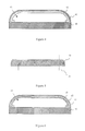
FIG. 4 is a structural diagram of a mobile terminal in an embodiment of the present invention;
FIG. 5 is a structural diagram of a middle frame in an embodiment of the present invention;
FIG. 6 is a structural diagram of a mobile terminal in an embodiment of the present invention;
FIG. 7 is a structural diagram of a bottom frame in an embodiment of the present invention;
FIG. 8 is a structural diagram of a mobile terminal in an embodiment of the present invention;
FIG. 9 is a structural diagram of a mobile terminal in an embodiment of the present invention;
FIG. 10 is a structural diagram of a mobile terminal in an embodiment of the present invention.
DETAILED DESCRIPTION
The present invention will now be described more fully hereinafter with reference to the accompanying drawings, in which exemplary embodiments of the invention are shown. This invention may, however, be embodied in many different forms and should not be construed as limited to the embodiments set forth herein. Rather, these embodiments are provided so that this disclosure will be thorough and complete, and will fully convey the scope of the invention to those skilled in the art. Like reference numerals refer to like elements throughout.
The terminology used herein is for the purpose of describing particular embodiments only and is not intended to be limiting of the invention. As used herein, the singular forms “a”, “an” and “the” are intended to include the plural forms as well, unless the context clearly indicates otherwise. It will be further understood that the terms “comprises” and/or “comprising,” or “includes” and/or “including” or “has” and/or “having” when used herein, specify the presence of stated features, regions, integers, steps, operations, elements, and/or components, but do not preclude the presence or addition of one or more other features, regions, integers, steps, operations, elements, components, and/or groups thereof.
Unless otherwise defined, all terms (including technical and scientific terms) used herein have the same meaning as commonly understood by one of ordinary skill in the art to which this invention belongs. It will be further understood that terms, such as those defined in commonly used dictionaries, should be interpreted as having a meaning that is consistent with their meaning in the context of the relevant art and the present disclosure, and will not be interpreted in an idealized or overly formal sense unless expressly so defined herein.
As used herein, “around”, “about” or “approximately” shall generally mean within 20 percent, preferably within 10 percent, and more preferably within 5 percent of a given value or range. Numerical quantities given herein are approximate, meaning that the term “around”, “about” or “approximately” can be inferred if not expressly stated.
As used herein, the term “plurality” means a number greater than one.
Hereinafter, certain exemplary embodiments according to the present disclosure will be described with reference to the accompanying drawings.
The smartphone provided in the embodiment of the invention moves the structures such as the handset, the radio module and the physical buttons which are configured on the front surface of the mobile phone presently to the side of the phone, namely the front side of the phone is used only for the display area, and so that the display area be able to extend to the entire front surface of the mobile phone, to effectively enhance the beauty of appearance of the mobile phone, and meanwhile to improve the user experience.
Hereinafter, the smartphone of the invention will be described in detail with reference to accompanying drawings and exemplary embodiments.
FIG. 2 is a structural diagram for the smartphone of the application, FIG. 3 is a cutaway diagram of FIG. 2 at A-A.
As shown in FIG. 2, a smartphone of this embodiment comprises a phone body 2, the phone body 2 has a front side (not marked in the figure, can be understood as a side surface of the phone body 2 facing the readers) for configuring the first display area (namely the main operating touch area of mobile phone) and a back side (not marked in the figure, can be understood as a side surface back of the phone body 2 opposite to the readers) opposite to the front side, and a top side 211, a bottom side 212 and vertical sides 213 on two sides are configured between the front side and the back side (namely the side of the phone body 2) of the phone body 2.
Further, as shown in FIG. 3, the above-mentioned phone body 2 comprises a back shell 201 having a groove structure, a circuit board 202, a screen module 203 and a transparent cover plate 204, both the circuit board 202 and the screen module 203 can be put into the above-mentioned groove structure, and the circuit board 202 is connected to the screen module 203 to drive the screen module 203 to shine for forming the display area; and the transparent cover plate 204 covers on the back shell 201 to seal the groove structure and to form a closed space area for containing and protecting the circuit board 202 and the screen module 203, and the light emitted by the screen module 203 penetrates through the transparent cover plate 204 to form a first display area 21 on the front surface of the phone body 2, the first display area 21 can be used for the touch screen or the main screen in multi-screens of the phone body 2.
Preferably, a ratio of area of the above-mentioned first display area 21 to the surface (the surface used to cover) of the cover area of the transparent cover plate 204 R is no less than 0.9, such as the R is 0.9, 0.92, 0.95 or 0.98, and even may be equal to 1.
Preferably, the above-mentioned screen module 203 may be a liquid crystal display module or an AMOLED display module, such as a flexible AMOLED display module, etc.; accordingly, the sides of the phone body 2, such as the top side 211 and/or the bottom side 212 and/or the vertical side 213, can be provided with flexible sides, to form the side display area.
Further, the above-mentioned phone body 2 also comprises a handset (not marked in figure) configured in the side, namely the handset can be configured in the groove structure and aligned to any one side edge (such as the top side, the bottom side and the vertical side location, etc.) of the back shell 201; in addition, the above-mentioned handset is selectively exposed to the front side the first display area 21, the top side or the vertical sides, and is configured near the position of the top side, for example, when the handset is configured on the vertical sides 213, the handset is configured near the top side 211, and is exposed to the front area of the first display area through an short angle or an opening configured on the transparent cover plate, so that the users can hear the sound played by the handset.
Preferably, the above-mentioned handset may comprise a handset module (not shown) and openings (not shown), and the handset module is configured in the back shell 201 (such as in the above-mentioned groove structure), the openings can be through-holes configured on the transparent cover plate 204 or through-holes formed by the gap on the transparent cover plate 204 together with the back shell 201, to penetrate the transparent cover plate 204, to transmit the sound played by the handset module to the outside of the phone body 2, so that the users hear the sound.
Further, the above-mentioned phone body 2 further comprises a radio module (not shown), the radio module is configured to the position in relative to the above-mentioned receiver module, for example, the radio module is configured to the position in relative to the receiver module on the bottom side 212 of the phone body 2, or the vertical sides 213 adjacent to the bottom side 212, so as to collect the user's voice.
Preferably, based on the openings in the above-mentioned handset, the back shell 201 and the transparent cover plate 204 are also provided with openings for transmitting voice in relative to the receiver module, the structure of the openings can be equal or approximate to the openings of the handset, and they may also be formed by any known way.
Further, the above-mentioned phone body 2 also comprises a camera module (not shown) which is configured on any other surfaces of the phone body 2 except the front side, namely the front side of the phone body 2 is not provided with a front camera.
Preferably, the camera module can be configured on the back side of the phone body 2, and a second display area (not shown in figure) is formed on the back side, namely the phone body 2 is a multi-screen smartphone; and the second display area can be displayed by one or more of the AMOLED screen, LCD display, electronic paper display, etc., namely a single display or multiple displays can be configured on the second display area, and can be configured according to the requirement.
Preferably, the above-mentioned second display area can be used as self-timer for users, the resolution of the second display area is no greater than that of the first display area.
In summary, in the above-mentioned embodiment of the invention, the necessary structures such as the handset are configured on the side or the back side of the mobile phone (aligning to the edges of the mobile phone), and the unnecessary structures such as physical buttons (e.g., home key, volume key, etc.), front-facing camera are removed, so that the entire front surface of the mobile phone can be used to form the display area to realize the full-screen display without borders, and to enhance the beauty of the appearance of the smartphone, thus to effectively improve the user experience.
The present application also discloses a mobile terminal and a method for producing the same, and the present invention will be described in further detail with reference to the accompanying drawings.
Embodiment I
Because the flexible curved screen does not improve a lot for the black edge, when the user looks the flexible curved screen from a side, it is easy to find there are still black edges on both sides of the flexible curved screen, resulting in the obvious defects for the display effect of viewing from the side.
Referring to FIG. 4, the embodiment discloses an edge-to-edge mobile terminal, comprising:
a bottom frame 40;
a glass cover 41;
a screen module 42 covering the bottom frame 4;
wherein the glass cover 41 covers the screen module 42 and two edges of both sides of the glass cover 41 connect to the bottom frame 40;
both the screen module 42 and the glass cover 41 have an arch opposite to the bottom frame 40;
two edges of both sides of the screen module 42 extend over both sides of the glass cover 41 and are covered by the bottom frame 40.
In the above technical solution, both the screen module 42 and the glass cover 41 have an arch opposite to the bottom frame 40, so that neither the front surface of the screen module 42 nor the two side surfaces of the screen module 42 have black edges; the front surface and side surface may be smooth so as to minimize the interference of the arch affecting the display effect.
As an alternative embodiment, the arch of the screen module 42 opposite to the bottom frame 40 and the arch of the glass cover opposite to the bottom frame 40 is arranged not only in the lateral section of the mobile terminal but also in the longitudinal section of the mobile terminal.
As an alternative embodiment, the mobile terminal may be a device such as a mobile phone, a tablet computer, a media player, a data acquisition device, or the like.
Referring to FIG. 4, in a preferred embodiment, the mobile terminal further comprising:
a circuit board arranged in a space generated by arching of the screen module, the bottom frame covering the space.
In the above technical solution, compared to the display panel in which the circuit board is arranged in the bottom frame, the bottom frame 40 of the present invention has a small advantage that the thickness of the bottom frame 40 is small, the black edge is improved by the arch, and total thickness of the display panel will not be increased.
Referring to FIG. 5, in a preferred embodiment, the mobile terminal further comprising:
a middle frame 50 by which the circuit board is fixed in the space 43.
In the above technical solution, the middle frame 50 may be provided with a matching design 51 as shown in FIG. 5, the matching design 51 is used to match the circuit board so that the circuit board is positioned and mounted in the middle frame 50 accurately and rapidly; the matching design 51 may be a rod-like positioning structure, a groove or other auxiliary assembly structure.
Embodiment II
Referring to FIG. 6, in a preferred embodiment, the screen module 42 comprises a touch panel 61 and a display screen 62, the display screen covers the touch panel.
In the above technical solution, the touch panel 61 and the display screen 62 are only a preferable embodiment, and the situation that the screen module 42 is a single layer structure or other composite structure is not excluded
Referring to FIG. 7 and FIG. 8, in a preferred embodiment, the bottom frame 40 is provided with at least one groove 71, two edges of both sides of the touch panel 61 and two edges of both sides of the display screen 62 extend into the at least one groove 71 respectively
In the above technical solution, the two edges extended from both sides of the touch panel 61 and the display screen 62 are buried in the groove 71 of the bottom frame 40, so as to avoid the other ways of increasing the thickness of the display panel, thereby the thickness of the display panel is reduced, and the deformation of the bottom frame 40 caused by the force of the touch panel 61 and the display screen 62 acting directly on the bottom frame 40 is avoided.
Embodiment III
Referring to FIG. 9, in a preferred embodiment, the two edges of both sides of the screen module 42 have an inward first bend 91 respectively.
In the above technical solution, the extended screen module 42 is directed inward by the first bend 91, the situation that the first bend is extended in a direction along the thickness of the mobile terminal is avoided.
As a preferred embodiment, the first bend has a bending angle a belonging to (00, 180°].
As a preferred embodiment, the bending angle of the first bend is 90°, a bottom of the screen module 42 which is at an outside of the first bend 91 is flush with bottoms of both sides of the glass cover 41.
In the above technical solution, the bottom which is outside of the bend 91 and the bottoms of both sides of the glass cover 41 can be smoothly engaged with the upper surface of the bottom frame 40, so as to improve the reliability of the package.
Referring to FIG. 9, in a preferred embodiment, the screen module 42 and two sides of the glass cover 41 are bent to form the arch.
As a preferred embodiment, the display screen 62 is a flexible display device, and bending on both sides of the screen module 42 is achieved by bending the flexible display device.
As a preferred embodiment, the flexible display device is an AMOLED display device.
Embodiment IV
Referring to FIG. 10, in a preferred embodiment, the arch is formed by second bends at both sides of the screen module 42 and the glass cover 41.
As a preferred embodiment, each of the second bends 102 has a bending angle b belonging to [20°, 90° ].
In the above technical solution, by controlling the bending angle b and/or the bending initial position of the second bend 102, it is possible to control the extent and size to which the screen is arched and to reserve space for the installation of components such as the circuit board.
Referring to FIG. 10, in a preferred embodiment, both sides of the bottom frame 40 have an upward flanges 101 respectively, the glass cover 41 is connected to the flange 101.
In the above technical solution, the force applying to the bottom frame 40 is transferred to the flange 101 by setting the flange 101, so that the deformation of the bottom frame 10 caused by the force is avoided.
Referring to the dotted line of FIG. 10, in a preferred embodiment, the flange 101 has an outside wall with a flat surface, and outside of the glass cover 41 is flush with the outside wall, so that the situation that the width of the display panel is increased due to the outside of the glass cover 41 being extended out to the outside wall of the flange 101 is avoid.
The foregoing is only the preferred embodiments of the invention, not thus limiting embodiments and scope of the invention, those skilled in the art should be able to realize that the schemes obtained from the content of specification and figures of the invention are within the scope of the invention.

Claims (14)

What is claimed is:
1. An edge-to-edge mobile terminal, comprising:
a bottom frame;
a glass cover;
a screen module covering the bottom frame;
wherein, the glass cover covers the screen module and two edges of both sides of the glass cover connect to the bottom frame;
both the screen module and the glass cover have an arch opposite to the bottom frame;
two edges of both sides of the screen module extend over both sides of the glass cover and are covered by the bottom frame;
wherein the two edges of both sides of the screen module have an inward first bend respectively.
2. The mobile terminal according to claim 1, further comprising:
a circuit board arranged in a space generated by arching of the screen module, the bottom frame covering the space.
3. The mobile terminal according to claim 2, further comprising:
a middle frame by which the circuit board is fixed in the space.
4. The mobile terminal according to claim 1, wherein the screen module comprises a touch panel and a display screen, the display screen covers the touch panel.
5. The mobile terminal according to claim 4, wherein the bottom frame is provided with at least one groove, two edges of both sides of the touch panel and two edges of both sides of the display screen extend into the at least one groove respectively.
6. The mobile terminal according to claim 4, wherein the screen module and two sides of the glass cover are bent to form the arch.
7. The mobile terminal according to claim 6, wherein the display screen is a flexible display device, and bending on both sides of the screen module is achieved by bending the flexible display device.
8. The mobile terminal according to claim 7, wherein the flexible display device is an AMOLED display device.
9. The mobile terminal according to claim 1, wherein the first bend has a bending angle belonging to (0°, 180°].
10. The mobile terminal according to claim 9, wherein the bending angle of the first bend is 90°, a bottom of the screen module which is at an outside of the first bend is flush with bottoms of both sides of the glass cover.
11. The mobile terminal according to claim 1, wherein the arch is formed by second bends at both sides of the screen module and the glass cover.
12. The mobile terminal according to claim 11, wherein each of the second bends has a bending angle belonging to [20°, 90°].
13. The mobile terminal according to claim 1, wherein both sides of the bottom frame have an upward flange respectively, the glass cover is connected to the flange.
14. The mobile terminal according to claim 13, wherein the flange has an outside wall with a flat surface, and outside of the glass cover is flush with the outside wall.
US15/682,058 2015-06-12 2017-08-21 Edge-to-edge mobile terminal Active US10090361B2 (en)

Priority Applications (1)

Application Number Priority Date Filing Date Title
US15/682,058 US10090361B2 (en) 2015-06-12 2017-08-21 Edge-to-edge mobile terminal

Applications Claiming Priority (6)

Application Number Priority Date Filing Date Title
US201562174636P 2015-06-12 2015-06-12
US15/166,554 US9749450B2 (en) 2015-06-12 2016-05-27 Smartphone
CN201710156054.0A CN106821497B (en) 2017-03-16 2017-03-16 Accurate positioning and treatment method and auxiliary device for target site
CN201710156054 2017-03-16
CN201710156054.0 2017-03-16
US15/682,058 US10090361B2 (en) 2015-06-12 2017-08-21 Edge-to-edge mobile terminal

Related Parent Applications (1)

Application Number Title Priority Date Filing Date
US15/166,554 Continuation-In-Part US9749450B2 (en) 2015-06-12 2016-05-27 Smartphone

Publications (2)

Publication Number Publication Date
US20170345876A1 US20170345876A1 (en) 2017-11-30
US10090361B2 true US10090361B2 (en) 2018-10-02

Family

ID=60418900

Family Applications (1)

Application Number Title Priority Date Filing Date
US15/682,058 Active US10090361B2 (en) 2015-06-12 2017-08-21 Edge-to-edge mobile terminal

Country Status (1)

Country Link
US (1) US10090361B2 (en)

Families Citing this family (10)

* Cited by examiner, † Cited by third party
Publication number Priority date Publication date Assignee Title
CN108900671A (en) * 2018-06-29 2018-11-27 维沃移动通信有限公司 A kind of terminal device
CN108881546A (en) * 2018-07-03 2018-11-23 Oppo(重庆)智能科技有限公司 The display component of electronic device and electronic device with it
CN110460717B (en) * 2019-07-10 2021-05-28 维沃移动通信有限公司 Terminal control method and mobile terminal
CN110798552A (en) * 2019-09-19 2020-02-14 华为技术有限公司 Volume adjusting method and electronic equipment
CN111833720B (en) * 2020-01-13 2021-08-31 昆山国显光电有限公司 Display panel and display device
CN111787140A (en) * 2020-06-24 2020-10-16 维沃移动通信(杭州)有限公司 Screen control method and device and electronic equipment
CN111653193B (en) * 2020-06-30 2023-01-10 京东方科技集团股份有限公司 Screen assembly and display device
CN111863903B (en) * 2020-07-23 2023-04-18 武汉天马微电子有限公司 Display panel, manufacturing method thereof and display device
WO2022213722A1 (en) * 2021-04-07 2022-10-13 Oppo广东移动通信有限公司 Electronic device and assembly method therefor
CN216435327U (en) * 2021-06-09 2022-05-03 荣耀终端有限公司 Display device and electronic apparatus

Citations (16)

* Cited by examiner, † Cited by third party
Publication number Priority date Publication date Assignee Title
US20100073593A1 (en) * 2008-09-22 2010-03-25 Hitachi Displays, Ltd. Liquid crystal display device
US20110253835A1 (en) 2010-04-20 2011-10-20 Be Intellectual Property, Inc. Aircraft interior lavatory
US20120139821A1 (en) * 2010-12-03 2012-06-07 Jongmoo Kim Organic Light Emitting Display Device and Method for Manufacturing the Same
US20120299850A1 (en) * 2011-05-24 2012-11-29 Samsung Electronics Co., Ltd. Integrated digitizer display
US8334863B2 (en) * 2007-12-24 2012-12-18 Ignis Innovation Inc. Display system with a solar cell and device having the same
CN103841222A (en) 2012-11-20 2014-06-04 安谷通信技术(深圳)有限公司 Mobile phone with full-screen display function
US20140267090A1 (en) 2013-03-13 2014-09-18 Ericom Software Ltd. Method for displaying a remote desktop on a portable touch screen device
CN104601757A (en) 2015-01-19 2015-05-06 余勇 Design of totally non-frame smart phone
US20150123984A1 (en) * 2013-11-01 2015-05-07 Samsung Electronics Co., Ltd. Method for processing data and electronic device thereof
US9075612B2 (en) * 2013-05-10 2015-07-07 Jinrong Yang System and method for managing display power consumption
US20150253835A1 (en) * 2014-03-05 2015-09-10 Samsung Electronics Co., Ltd. Methods of constraining performance of a mobile device using an application processor, and related mobile devices
US9298220B2 (en) * 2014-09-02 2016-03-29 Samsung Electronics Co., Ltd. Curved display and electronic device including the same
US9342105B2 (en) * 2014-09-02 2016-05-17 Samsung Electronics Co., Ltd. Curved display and electronic device including the same
US9480174B2 (en) * 2012-10-11 2016-10-25 Samsung Display Co., Ltd. Flexible display device
US9509359B2 (en) * 2012-11-19 2016-11-29 Nec Corporation Mobile terminal device
US9674922B2 (en) * 2013-03-14 2017-06-06 Google Technology Holdings LLC Display side edge assembly and mobile device including same

Patent Citations (16)

* Cited by examiner, † Cited by third party
Publication number Priority date Publication date Assignee Title
US8334863B2 (en) * 2007-12-24 2012-12-18 Ignis Innovation Inc. Display system with a solar cell and device having the same
US20100073593A1 (en) * 2008-09-22 2010-03-25 Hitachi Displays, Ltd. Liquid crystal display device
US20110253835A1 (en) 2010-04-20 2011-10-20 Be Intellectual Property, Inc. Aircraft interior lavatory
US20120139821A1 (en) * 2010-12-03 2012-06-07 Jongmoo Kim Organic Light Emitting Display Device and Method for Manufacturing the Same
US20120299850A1 (en) * 2011-05-24 2012-11-29 Samsung Electronics Co., Ltd. Integrated digitizer display
US9480174B2 (en) * 2012-10-11 2016-10-25 Samsung Display Co., Ltd. Flexible display device
US9509359B2 (en) * 2012-11-19 2016-11-29 Nec Corporation Mobile terminal device
CN103841222A (en) 2012-11-20 2014-06-04 安谷通信技术(深圳)有限公司 Mobile phone with full-screen display function
US20140267090A1 (en) 2013-03-13 2014-09-18 Ericom Software Ltd. Method for displaying a remote desktop on a portable touch screen device
US9674922B2 (en) * 2013-03-14 2017-06-06 Google Technology Holdings LLC Display side edge assembly and mobile device including same
US9075612B2 (en) * 2013-05-10 2015-07-07 Jinrong Yang System and method for managing display power consumption
US20150123984A1 (en) * 2013-11-01 2015-05-07 Samsung Electronics Co., Ltd. Method for processing data and electronic device thereof
US20150253835A1 (en) * 2014-03-05 2015-09-10 Samsung Electronics Co., Ltd. Methods of constraining performance of a mobile device using an application processor, and related mobile devices
US9342105B2 (en) * 2014-09-02 2016-05-17 Samsung Electronics Co., Ltd. Curved display and electronic device including the same
US9298220B2 (en) * 2014-09-02 2016-03-29 Samsung Electronics Co., Ltd. Curved display and electronic device including the same
CN104601757A (en) 2015-01-19 2015-05-06 余勇 Design of totally non-frame smart phone

Also Published As

Publication number Publication date
US20170345876A1 (en) 2017-11-30

Similar Documents

Publication Publication Date Title
US10090361B2 (en) Edge-to-edge mobile terminal
US9749450B2 (en) Smartphone
US11216138B2 (en) Display system and display device
US10764973B2 (en) Display device and electronic device
JP7542122B2 (en) Display Panel
US11171190B2 (en) Semiconductor device, input/output device, and electronic appliance
CN105892568B (en) Mobile terminal
TWI696284B (en) Display device
US10056043B2 (en) Image processing device, display system, and electronic device
CN106504645B (en) Flexible display panels and flexible display device
JP2023051989A (en) Display device
CN108563286B (en) Display device and manufacturing method thereof
KR20200090980A (en) Lcd display module and mobile terminal
US10521040B2 (en) Display screen assembly, manufacturing method thereof and electronic device
CN104954519A (en) Smart mobile phone
CN102857601A (en) Mobile terminal
CN102778929B (en) Mobile terminal
KR20230088896A (en) display device
CN213342445U (en) Television system, television, electronic device, and display device
KR20230125595A (en) Display module and display device
KR20150059712A (en) Home Theater Equipment and Home Theater System

Legal Events

Date Code Title Description
AS Assignment

Owner name: EVERDISPLAY OPTRONICS (SHANGHAI) LIMITED, CHINA

Free format text: ASSIGNMENT OF ASSIGNORS INTEREST;ASSIGNORS:CHEN, JR HONG;HUANG, CHIEN ER;PAN, XINYE;AND OTHERS;SIGNING DATES FROM 20170816 TO 20170821;REEL/FRAME:043519/0897

STCF Information on status: patent grant

Free format text: PATENTED CASE

AS Assignment

Owner name: EVERDISPLAY OPTRONICS (SHANGHAI) CO., LTD., CHINA

Free format text: CHANGE OF NAME;ASSIGNOR:EVERDISPLAY OPTRONICS (SHANGHAI) LIMITED;REEL/FRAME:053395/0865

Effective date: 20200717

MAFP Maintenance fee payment

Free format text: PAYMENT OF MAINTENANCE FEE, 4TH YEAR, LARGE ENTITY (ORIGINAL EVENT CODE: M1551); ENTITY STATUS OF PATENT OWNER: LARGE ENTITY

Year of fee payment: 4