US10088161B2 - Gas turbine engine wall assembly with circumferential rail stud architecture - Google Patents
Gas turbine engine wall assembly with circumferential rail stud architecture Download PDFInfo
- Publication number
- US10088161B2 US10088161B2 US15/038,906 US201415038906A US10088161B2 US 10088161 B2 US10088161 B2 US 10088161B2 US 201415038906 A US201415038906 A US 201415038906A US 10088161 B2 US10088161 B2 US 10088161B2
- Authority
- US
- United States
- Prior art keywords
- rail
- liner panel
- cold side
- circumferential rail
- axial
- Prior art date
- Legal status (The legal status is an assumption and is not a legal conclusion. Google has not performed a legal analysis and makes no representation as to the accuracy of the status listed.)
- Active, expires
Links
Images




Classifications
-
- F—MECHANICAL ENGINEERING; LIGHTING; HEATING; WEAPONS; BLASTING
- F23—COMBUSTION APPARATUS; COMBUSTION PROCESSES
- F23R—GENERATING COMBUSTION PRODUCTS OF HIGH PRESSURE OR HIGH VELOCITY, e.g. GAS-TURBINE COMBUSTION CHAMBERS
- F23R3/00—Continuous combustion chambers using liquid or gaseous fuel
- F23R3/002—Wall structures
-
- F—MECHANICAL ENGINEERING; LIGHTING; HEATING; WEAPONS; BLASTING
- F01—MACHINES OR ENGINES IN GENERAL; ENGINE PLANTS IN GENERAL; STEAM ENGINES
- F01D—NON-POSITIVE DISPLACEMENT MACHINES OR ENGINES, e.g. STEAM TURBINES
- F01D25/00—Component parts, details, or accessories, not provided for in, or of interest apart from, other groups
- F01D25/08—Cooling; Heating; Heat-insulation
- F01D25/12—Cooling
-
- F—MECHANICAL ENGINEERING; LIGHTING; HEATING; WEAPONS; BLASTING
- F02—COMBUSTION ENGINES; HOT-GAS OR COMBUSTION-PRODUCT ENGINE PLANTS
- F02C—GAS-TURBINE PLANTS; AIR INTAKES FOR JET-PROPULSION PLANTS; CONTROLLING FUEL SUPPLY IN AIR-BREATHING JET-PROPULSION PLANTS
- F02C7/00—Features, components parts, details or accessories, not provided for in, or of interest apart form groups F02C1/00 - F02C6/00; Air intakes for jet-propulsion plants
- F02C7/12—Cooling of plants
- F02C7/16—Cooling of plants characterised by cooling medium
- F02C7/18—Cooling of plants characterised by cooling medium the medium being gaseous, e.g. air
-
- F—MECHANICAL ENGINEERING; LIGHTING; HEATING; WEAPONS; BLASTING
- F23—COMBUSTION APPARATUS; COMBUSTION PROCESSES
- F23R—GENERATING COMBUSTION PRODUCTS OF HIGH PRESSURE OR HIGH VELOCITY, e.g. GAS-TURBINE COMBUSTION CHAMBERS
- F23R3/00—Continuous combustion chambers using liquid or gaseous fuel
- F23R3/005—Combined with pressure or heat exchangers
-
- F—MECHANICAL ENGINEERING; LIGHTING; HEATING; WEAPONS; BLASTING
- F23—COMBUSTION APPARATUS; COMBUSTION PROCESSES
- F23R—GENERATING COMBUSTION PRODUCTS OF HIGH PRESSURE OR HIGH VELOCITY, e.g. GAS-TURBINE COMBUSTION CHAMBERS
- F23R3/00—Continuous combustion chambers using liquid or gaseous fuel
- F23R3/007—Continuous combustion chambers using liquid or gaseous fuel constructed mainly of ceramic components
-
- F—MECHANICAL ENGINEERING; LIGHTING; HEATING; WEAPONS; BLASTING
- F23—COMBUSTION APPARATUS; COMBUSTION PROCESSES
- F23R—GENERATING COMBUSTION PRODUCTS OF HIGH PRESSURE OR HIGH VELOCITY, e.g. GAS-TURBINE COMBUSTION CHAMBERS
- F23R3/00—Continuous combustion chambers using liquid or gaseous fuel
- F23R3/42—Continuous combustion chambers using liquid or gaseous fuel characterised by the arrangement or form of the flame tubes or combustion chambers
- F23R3/50—Combustion chambers comprising an annular flame tube within an annular casing
-
- F—MECHANICAL ENGINEERING; LIGHTING; HEATING; WEAPONS; BLASTING
- F23—COMBUSTION APPARATUS; COMBUSTION PROCESSES
- F23R—GENERATING COMBUSTION PRODUCTS OF HIGH PRESSURE OR HIGH VELOCITY, e.g. GAS-TURBINE COMBUSTION CHAMBERS
- F23R3/00—Continuous combustion chambers using liquid or gaseous fuel
- F23R3/42—Continuous combustion chambers using liquid or gaseous fuel characterised by the arrangement or form of the flame tubes or combustion chambers
- F23R3/60—Support structures; Attaching or mounting means
-
- F—MECHANICAL ENGINEERING; LIGHTING; HEATING; WEAPONS; BLASTING
- F05—INDEXING SCHEMES RELATING TO ENGINES OR PUMPS IN VARIOUS SUBCLASSES OF CLASSES F01-F04
- F05D—INDEXING SCHEME FOR ASPECTS RELATING TO NON-POSITIVE-DISPLACEMENT MACHINES OR ENGINES, GAS-TURBINES OR JET-PROPULSION PLANTS
- F05D2220/00—Application
- F05D2220/30—Application in turbines
- F05D2220/32—Application in turbines in gas turbines
- F05D2220/323—Application in turbines in gas turbines for aircraft propulsion, e.g. jet engines
-
- F—MECHANICAL ENGINEERING; LIGHTING; HEATING; WEAPONS; BLASTING
- F05—INDEXING SCHEMES RELATING TO ENGINES OR PUMPS IN VARIOUS SUBCLASSES OF CLASSES F01-F04
- F05D—INDEXING SCHEME FOR ASPECTS RELATING TO NON-POSITIVE-DISPLACEMENT MACHINES OR ENGINES, GAS-TURBINES OR JET-PROPULSION PLANTS
- F05D2230/00—Manufacture
- F05D2230/60—Assembly methods
-
- F—MECHANICAL ENGINEERING; LIGHTING; HEATING; WEAPONS; BLASTING
- F05—INDEXING SCHEMES RELATING TO ENGINES OR PUMPS IN VARIOUS SUBCLASSES OF CLASSES F01-F04
- F05D—INDEXING SCHEME FOR ASPECTS RELATING TO NON-POSITIVE-DISPLACEMENT MACHINES OR ENGINES, GAS-TURBINES OR JET-PROPULSION PLANTS
- F05D2240/00—Components
- F05D2240/35—Combustors or associated equipment
-
- F—MECHANICAL ENGINEERING; LIGHTING; HEATING; WEAPONS; BLASTING
- F05—INDEXING SCHEMES RELATING TO ENGINES OR PUMPS IN VARIOUS SUBCLASSES OF CLASSES F01-F04
- F05D—INDEXING SCHEME FOR ASPECTS RELATING TO NON-POSITIVE-DISPLACEMENT MACHINES OR ENGINES, GAS-TURBINES OR JET-PROPULSION PLANTS
- F05D2260/00—Function
- F05D2260/20—Heat transfer, e.g. cooling
- F05D2260/201—Heat transfer, e.g. cooling by impingement of a fluid
-
- F—MECHANICAL ENGINEERING; LIGHTING; HEATING; WEAPONS; BLASTING
- F05—INDEXING SCHEMES RELATING TO ENGINES OR PUMPS IN VARIOUS SUBCLASSES OF CLASSES F01-F04
- F05D—INDEXING SCHEME FOR ASPECTS RELATING TO NON-POSITIVE-DISPLACEMENT MACHINES OR ENGINES, GAS-TURBINES OR JET-PROPULSION PLANTS
- F05D2260/00—Function
- F05D2260/30—Retaining components in desired mutual position
- F05D2260/31—Retaining bolts or nuts
-
- F—MECHANICAL ENGINEERING; LIGHTING; HEATING; WEAPONS; BLASTING
- F16—ENGINEERING ELEMENTS AND UNITS; GENERAL MEASURES FOR PRODUCING AND MAINTAINING EFFECTIVE FUNCTIONING OF MACHINES OR INSTALLATIONS; THERMAL INSULATION IN GENERAL
- F16B—DEVICES FOR FASTENING OR SECURING CONSTRUCTIONAL ELEMENTS OR MACHINE PARTS TOGETHER, e.g. NAILS, BOLTS, CIRCLIPS, CLAMPS, CLIPS OR WEDGES; JOINTS OR JOINTING
- F16B33/00—Features common to bolt and nut
- F16B33/004—Sealing; Insulation
-
- F—MECHANICAL ENGINEERING; LIGHTING; HEATING; WEAPONS; BLASTING
- F23—COMBUSTION APPARATUS; COMBUSTION PROCESSES
- F23R—GENERATING COMBUSTION PRODUCTS OF HIGH PRESSURE OR HIGH VELOCITY, e.g. GAS-TURBINE COMBUSTION CHAMBERS
- F23R2900/00—Special features of, or arrangements for continuous combustion chambers; Combustion processes therefor
- F23R2900/00017—Assembling combustion chamber liners or subparts
-
- F—MECHANICAL ENGINEERING; LIGHTING; HEATING; WEAPONS; BLASTING
- F23—COMBUSTION APPARATUS; COMBUSTION PROCESSES
- F23R—GENERATING COMBUSTION PRODUCTS OF HIGH PRESSURE OR HIGH VELOCITY, e.g. GAS-TURBINE COMBUSTION CHAMBERS
- F23R2900/00—Special features of, or arrangements for continuous combustion chambers; Combustion processes therefor
- F23R2900/03041—Effusion cooled combustion chamber walls or domes
-
- F—MECHANICAL ENGINEERING; LIGHTING; HEATING; WEAPONS; BLASTING
- F23—COMBUSTION APPARATUS; COMBUSTION PROCESSES
- F23R—GENERATING COMBUSTION PRODUCTS OF HIGH PRESSURE OR HIGH VELOCITY, e.g. GAS-TURBINE COMBUSTION CHAMBERS
- F23R2900/00—Special features of, or arrangements for continuous combustion chambers; Combustion processes therefor
- F23R2900/03044—Impingement cooled combustion chamber walls or subassemblies
-
- Y—GENERAL TAGGING OF NEW TECHNOLOGICAL DEVELOPMENTS; GENERAL TAGGING OF CROSS-SECTIONAL TECHNOLOGIES SPANNING OVER SEVERAL SECTIONS OF THE IPC; TECHNICAL SUBJECTS COVERED BY FORMER USPC CROSS-REFERENCE ART COLLECTIONS [XRACs] AND DIGESTS
- Y02—TECHNOLOGIES OR APPLICATIONS FOR MITIGATION OR ADAPTATION AGAINST CLIMATE CHANGE
- Y02T—CLIMATE CHANGE MITIGATION TECHNOLOGIES RELATED TO TRANSPORTATION
- Y02T50/00—Aeronautics or air transport
- Y02T50/60—Efficient propulsion technologies, e.g. for aircraft
Definitions
- the present disclosure relates to a gas turbine engine and, more particularly, to a combustor section therefor.
- Gas turbine engines such as those that power modern commercial and military aircraft, generally include a compressor section to pressurize an airflow, a combustor section to burn a hydrocarbon fuel in the presence of the pressurized air, and a turbine section to extract energy from the resultant combustion gases.
- the combustor section typically includes a combustion chamber fondled by an inner and outer wall assembly.
- Each wall assembly includes a support shell lined with heat shields often referred to as liner panels.
- dilution passages direct airflow to condition air within the combustion chamber.
- the shells may have relatively small air impingement passages to direct cooling air to impingement cavities between the support shell and the liner panels. This cooling air exits numerous effusion passages through the liner panels to effusion cool the passages and film cool a hot side of the liner panels to reduce direct exposure to the combustion gases.
- a liner panel for use in a gas turbine engine has a hot side and a cold side.
- This liner panel includes a rail extending from the cold side, and a multiple of studs extending from the cold side. At least one of the multiple of studs extend from, in part, the rail.
- each of the multiple of studs extends from the rail.
- the rail is an intermediate circumferential rail.
- a perimeter rail is included that extends around the liner panel to at least partially define an impingement cavity therein.
- the intermediate rail is within the perimeter rail.
- the perimeter rail forms a generally rectilinear boundary around the cold side.
- the liner panel is rectilinear.
- the intermediate rail is circumferentially arranged.
- the intermediate rail follows an are formed by the cold side.
- a multiple of pedestals are included that extend from the cold side around the at least one of the multiple of studs.
- a liner panel for use in a gas turbine engine includes a forward circumferential rail; an aft circumferential rail axially aft of the forward circumferential rail; a first axial rail and a second axial rail that interconnects the aft circumferential rail and the forward circumferential rail; an intermediate circumferential rail that extends between the first axial rail and the second axial rail; and a multiple of studs that extend, in part, from the intermediate rail.
- the intermediate circumferential rail is parallel to the forward circumferential rail and the aft circumferential rail.
- a second intermediate circumferential rail is included that extends between the first axial rail and the second axial rail.
- a second multiple of studs are also included that extend from the second intermediate circumferential rail.
- the second intermediate circumferential rail is parallel to the intermediate circumferential rail.
- the liner panel is mountable within a combustor of the gas turbine engine.
- the liner panel includes a multiple of dilution passages therethrough.
- the multiple of dilution passages are located along a line generally parallel to the intermediate circumferential rail.
- a method of assembling a wall assembly within a gas turbine engine includes a locating a stud that extends in part from a rail of a liner panel through a support shell; and attaching a fastener onto the stud to retain the liner panel to the support shell.
- the method includes deflecting the support shell toward the liner panel to seal the rail with the support shell.
- the method includes defining an impingement cavity between the support shell and the liner panel.
- the method includes forming a dilution passage through the impingement cavity.
- FIG. 1 is a schematic cross-section of an example gas turbine engine architecture
- FIG. 2 is a schematic cross-section of another example gas turbine engine architecture
- FIG. 3 is an expanded longitudinal schematic sectional view of a combustor section according to one non-limiting embodiment that may be used with the example gas turbine engine architectures shown in FIGS. 1 and 2 ;
- FIG. 4 is an exploded partial sectional view of a portion of a combustor wall assembly
- FIG. 5 is a perspective view of a portion of a liner panel array
- FIG. 6 is an expanded longitudinal sectional view of a forward outer portion of a combustor wall assembly illustrating a contoured region of a support shell according to one disclosed non-limiting embodiment
- FIG. 7 is a perspective partial phantom view of one forward outer liner panel mounted to a support shell
- FIG. 8 is an expanded longitudinal sectional view of a forward outer portion of a combustor wall assembly illustrating a gap according to one disclosed non-limiting embodiment with a contoured region of the shell in a first relaxed position;
- FIG. 9 is an expanded longitudinal sectional view of a forward outer portion of a combustor wall assembly illustrating the contoured region of the shell in a second deformed position, closing the gap of FIG. 8 ;
- FIG. 10 is a perspective view of a forward outer liner panel of a combustor wall assembly according to one disclosed non-limiting embodiment
- FIG. 11 is a perspective view of a forward outer liner panel of a combustor wall assembly according to another disclosed non-limiting embodiment.
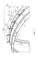
- FIG. 12 is an expanded perspective view of an aft outer liner panel with a multiple of circumferential rails according to another disclosed non-limiting embodiment to minimize leakage from both the neighboring rail and adjacent rails.
- FIG. 1 schematically illustrates a gas turbine engine 20 .
- the gas turbine engine 20 is disclosed herein as a two-spool turbo fan that generally incorporates a fan section 22 , a compressor section 24 , a combustor section 26 and a turbine section 28 .
- Alternative engine architectures 200 might include an augmentor section 12 , an exhaust duct section 14 and a nozzle section 16 in addition to the fan section 22 ′, compressor section 24 ′, combustor section 26 ′ and turbine section 28 ′ (see FIG. 2 ) among other systems or features.
- the fan section 22 drives air along a bypass flowpath and into the compressor section 24 .
- the compressor section 24 drives air along a core flowpath for compression and communication into the combustor section 26 , which then expands and directs the air through the turbine section 28 .
- a turbofan in the disclosed non-limiting embodiment, it should be understood that the concepts described herein are not limited to use with turbofans as the teachings may be applied to other types of turbine engines such as a turbojets, turboshafts, and three-spool (plus fan) turbofans wherein an intermediate spool includes an Intermediate Pressure Compressor (“IPC”) between a Low Pressure Compressor (“LPC”) and a High Pressure Compressor (“HPC”), and an Intermediate Pressure Turbine (“IPT”) between a High Pressure Turbine (“HPT”) and a Low Pressure Turbine (“LPT”).
- IPC Intermediate Pressure Compressor
- LPC Low Pressure Compressor
- HPC High Pressure Compressor
- IPT Intermediate Pressure Turbine
- the engine 20 generally includes a low spool 30 and a high spool 32 mounted for rotation about an engine central longitudinal axis A relative to an engine static structure 36 via several bearing structures 38 .
- the low spool 30 generally includes an inner shaft 40 that interconnects a fan 42 , a low pressure compressor (“LPC”) 44 and a low pressure turbine (“LPT”) 46 .
- the inner shaft 40 may drive the fan 42 directly or through a geared architecture 48 as shown in FIG. 1 to drive the fan 42 at a lower speed than the low spool 30 .
- An exemplary reduction transmission is an epicyclic transmission, namely a planetary or star gear system.
- the high spool 32 includes an outer shaft 50 that interconnects a high pressure compressor (“HPC”) 52 and a high pressure turbine (“HPT”) 54 .
- a combustor 56 is arranged between the HPC 52 and the HPT 54 .
- the inner shaft 40 and the outer shaft 50 are concentric and rotate about the engine central longitudinal axis A which is collinear with their longitudinal axes.
- Core airflow is compressed by the LPC 44 then the HPC 52 , mixed with the fuel and burned in the combustor 56 , then expanded over the HPT 54 and the LPT 46 .
- the LPT 46 and the HPT 54 rotationally drive the respective low spool 30 and the high spool 32 in response to the expansion.
- the main engine shafts 40 , 50 are supported at a plurality of points by the bearing systems 38 within the static structure 36 .
- the gas turbine engine 20 is a high-bypass geared aircraft engine.
- the gas turbine engine 20 bypass ratio is greater than about six (6:1).
- the geared architecture 48 can include an epicyclic gear train, such as a planetary gear system or other gear system.
- the example epicyclic gear train has a gear reduction ratio of greater than about 2.3, and in another example is greater than about 2.5:1.
- the geared turbofan enables operation of the low spool 30 at higher speeds which can increase the operational efficiency of the LPC 44 and the LPT 46 and render increased pressure in a fewer number of stages.
- a pressure ratio associated with the LPT 46 is pressure measured prior to the inlet of the LPT 46 as related to the pressure at the outlet of the LPT 46 prior to an exhaust nozzle of the gas turbine engine 20 .
- the bypass ratio of the gas turbine engine 20 is greater than about ten (10:1)
- the fan diameter is significantly larger than that of the LPC 44
- the LPT 46 has a pressure ratio that is greater than about five (5:1). It should be understood, however, that the above parameters are only exemplary of one embodiment of a geared architecture engine and that the present disclosure is applicable to other gas turbine engines including direct drive turbofans.
- a significant amount of thrust is provided by the bypass flow path due to the high bypass ratio.
- the fan section 22 of the gas turbine engine 20 is designed for a particular flight condition—typically cruise at about 0.8 Mach and about 35,000 feet. This flight condition, with the gas turbine engine 20 at its best fuel consumption, is also known as bucket cruise Thrust Specific Fuel Consumption (TSFC).
- TSFC Thrust Specific Fuel Consumption
- Fan Pressure Ratio is the pressure ratio across a blade of the fan section 22 without the use of a Fan Exit Guide Vane system.
- the low Fan Pressure Ratio according to one non-limiting embodiment of the example gas turbine engine 20 is less than 1.45.
- Low Corrected Fan Tip Speed is the actual fan tip speed divided by an industry standard temperature correction of (“Tram”/518.7) 0.5 .
- the Low Corrected Fan Tip Speed according to one non-limiting embodiment of the example gas turbine engine 20 is less than about 1150 fps (351 m/s).
- the combustor section 26 generally includes a combustor 56 with an outer combustor wall assembly 60 , an inner combustor wall assembly 62 and a diffuser case module 64 .
- the outer combustor wall assembly 60 and the inner combustor wall assembly 62 are spaced apart such that a combustion chamber 66 is defined therebetween.
- the combustion chamber 66 is generally annular in shape to surround the engine central longitudinal axis A.
- the outer combustor liner assembly 60 is spaced radially inward from an outer diffuser case 64 A of the diffuser case module 64 to define an outer annular plenum 76 .
- the inner combustor liner assembly 62 is spaced radially outward from an inner diffuser case 64 B of the diffuser case module 64 to define an inner annular plenum 78 . It should be understood that although a particular combustor is illustrated, other combustor types with various combustor liner arrangements will also benefit herefrom. It should be further understood that the disclosed cooling flow paths are but an illustrated embodiment and should not be limited only thereto.
- the combustor wall assemblies 60 , 62 contain the combustion products for direction toward the turbine section 28 .
- Each combustor wall assembly 60 , 62 generally includes a respective support shell 68 , 70 which supports one or more liner panels 72 A, 72 B (generally referred to as “ 72 ”) and 74 A, 74 B (generally referred to as “ 74 ”) mounted thereto that are arranged to form a liner array.
- the support shells 68 , 70 may be manufactured by, for example, the hydroforming of a sheet metal alloy to provide the generally cylindrical outer shell 68 and inner shell 70 .
- Each of the liner panels 72 , 74 may be generally rectilinear with a circumferential arc.
- the liner panels 72 , 74 may be manufactured of, for example, a nickel based super alloy, ceramic or other temperature resistant material.
- the liner array includes a multiple of forward liner panels 72 A and a multiple of aft liner panels 72 B that are circumferentially staggered to line the outer shell 68 .
- a multiple of forward liner panels 74 A and a multiple of aft liner panels 74 B are circumferentially staggered to line the inner shell 70 .
- the combustor 56 further includes a forward assembly 80 immediately downstream of the compressor section 24 to receive compressed airflow therefrom.
- the forward assembly 80 generally includes a cowl 82 , a bulkhead assembly 84 , and a multiple of swirlers 90 (one shown). Each of the swirlers 90 is circumferentially aligned with one of a multiple of fuel nozzles 86 (one shown) and the respective hood ports 94 to project through the bulkhead assembly 84 .
- the bulkhead assembly 84 includes a bulkhead support shell 96 secured to the combustor walls 60 , 62 , and a multiple of circumferentially distributed bulkhead liner panels 98 secured to the bulkhead support shell 96 around the swirler opening.
- the bulkhead support shell 96 is generally annular and the multiple of circumferentially distributed bulkhead liner panels 98 are segmented, typically one to each fuel nozzle 86 and swirler 90 .
- the cowl 82 extends radially between, and is secured to, the forward most ends of the combustor walls 60 , 62 .
- the cowl 82 includes a multiple of circumferentially distributed hood ports 94 that receive one of the respective multiple of fuel nozzles 86 and facilitates the direction of compressed air into the forward end of the combustion chamber 66 through a swirler opening 92 .
- Each fuel nozzle 86 may be secured to the diffuser case module 64 and project through one of the hood ports 94 and through the swirler opening 92 within the respective swirler 90 .
- the forward assembly 80 introduces core combustion air into the forward section of the combustion chamber 66 while the remainder enters the outer annular plenum 76 and the inner annular plenum 78 .
- the multiple of fuel nozzles 86 and adjacent structure generate a blended fuel-air mixture that supports stable combustion in the combustion chamber 66 .
- the outer and inner support shells 68 , 70 are mounted to a first row of Nozzle Guide Vanes (NGVs) 54 A in the HPT 54 .
- the NGVs 54 A are static engine components which direct core airflow combustion gases onto the turbine blades of the first turbine rotor in the turbine section 28 to facilitate the conversion of pressure energy into kinetic energy.
- the core airflow combustion gases are also accelerated by the NGVs 54 A because of their convergent shape and are typically given a “spin” or a “swirl” in the direction of turbine rotor rotation.
- the turbine rotor blades absorb this energy to drive the turbine rotor at high speed.
- a multiple of studs 100 extend from each of the liner panels 72 , 74 so as to permit an array (see FIG. 5 ) of the liner panels 72 , 74 to be mounted to their respective support shells 68 , 70 with fasteners 102 (see FIG. 6 ) such as nuts. That is, the studs 100 project rigidly from the liner panels 72 , 74 and through the respective support shells 68 , 70 to receive the fasteners 102 at a threaded section thereof.
- a multiple of cooling impingement passages 104 penetrate through the support shells 68 , 70 to allow air from the respective annular plenums 76 , 78 to enter cavities 106 formed in the combustor walls 60 , 62 between the respective support shells 68 , 70 and liner panels 72 , 74 .
- the cooling impingement passages 104 are generally normal to the surface of the liner panels 72 , 74 .
- the air in the cavities 106 provide cold side impingement cooling of the liner panels 72 , 74 that is generally defined herein as heat removal via internal convection.
- a multiple of effusion passages 108 penetrate through each of the liner panels 72 , 74 .
- the geometry of the passages e.g., diameter, shape, density, surface angle, incidence angle, etc.
- the combination of impingement passages 104 and effusion passages 108 may be referred to as an Impingement Film Floatwall (IFF) assembly.
- IFF Impingement Film Floatwall
- the effusion passages 108 allow the air to pass from the cavities 106 defined in part by a cold side 110 of the liner panels 72 , 74 to a hot side 112 of the liner panels 72 , 74 and thereby facilitate the formation of a thin, cool, insulating blanket or film of cooling air along the hot side 112 .
- the effusion passages 108 are generally more numerous than the impingement passages 104 to promote the development of film cooling along the hot side 112 to sheath the liner panels 72 , 74 .
- Film cooling as defined herein is the introduction of a relatively cooler air at one or more discrete locations along a surface exposed to a high temperature environment to protect that surface in the region of the air injection as well as downstream thereof.
- a multiple of dilution passages 116 may penetrate through both the respective support shells 68 , 70 and liner panels 72 , 74 along a common axis.
- the dilution passages 116 are located downstream of the forward assembly 80 to quench the hot combustion gases within the combustion chamber 66 by direct supply of cooling air from the respective annular plenums 76 , 78 .
- a portion of each of the respective support shells 68 , 70 is non-parallel with respect to the forward liner panels 72 A, 74 A to form a convergent passage 120 therebetween along a contoured region 124 . That is, the contoured region 124 is a radially displaced profile section of the respective support shells 68 , 70 with respect to the engine axis A.
- the inner support shell 70 as well as various other wall assemblies within a gas turbine engine such as within the walls of the augmentor section 12 , the exhaust duct section 14 and the nozzle section 16 (see FIG. 2 ) may alternatively or additionally benefit herefrom. That is, the contoured region 124 may be alternatively or additionally located within engine sections other than the combustor section 26 which utilize a support shell, liner panel type wall arrangement. The various contoured regions 124 form one or more convergent passages 120 for panel cooling air by varying the profile of the combustor shell adjacent to the respective liner panels.
- contours and configurations are possible to tailor the location of the effusion air exit, and optimize heat transfer, pressure loss, manufacturability, NOx reduction, etc.
- the contoured regions do not require additional hardware over conventional float wall combustor panels to create the convergence and are readily produced with current manufacturing methods.
- the contoured region 124 of the support shell 68 defines a hyperbolic cosine (COSH) profile in longitudinal cross-section that extends away from the forward liner panels 72 A. That is, the forward liner panels 72 A are generally linear in longitudinal cross-section, while the contoured region 124 is non-linear in longitudinal cross-section.
- each of the forward liner panels 72 A defines an axial length of about 1.5 inches (38 mm) and each may extend over a circumferential arc of about forty (40) degrees (one shown in FIG. 7 ).
- the contoured region 124 is located adjacent to a row of studs 100 A, and an intermediate circumferential rail 126 is located between a forward circumferential rail 128 and an aft circumferential rail 130 .
- Each of the studs 100 A may be at least partially surrounded by posts 132 to at least partially support the fastener 102 and operate as stand-offs between the support shell 68 and the forward liner panels 72 A.
- Each of the forward liner panels 72 A includes a single row of studs 100 A (Five shown in FIG. 7 ) that extend through respective stud apertures 134 in the support shell 68 .
- a center or “king” stud 100 Aa is received within a central circular stud aperture 134 a while the remainder of the studs 100 Ab are received within elongated apertures 134 b to facilitate operational thermal growth relative to the center or “king” stud 100 Aa ( FIG. 7 ).
- the contoured regions 124 form respective boundaries of impingement cavities 106 Aa, 106 Ab that respectively converge toward the forward circumferential rail 128 and the aft circumferential rail 130 .
- the cavity 106 A is subdivided by the intermediate circumferential rail 126 into the forward cavity 106 Aa and the aft cavity 106 Ab.
- the forward cavity 106 Aa and the aft cavity 106 Ab thereby accelerate and direct impingement airflow from impingement passages 104 on each respective side of the intermediate circumferential rail 126 toward forward effusion apertures 108 a and aft effusion apertures 108 b .
- the forward effusion apertures 108 a and the aft effusion apertures 108 b may define respective angles through the forward liner panels 72 A to direct effusion airflow generally forward and aft into the combustion chamber 66 . It should be appreciated that various contours and configurations are possible to tailor the location of the effusion air passages to optimize heat transfer, pressure loss, manufacturability, etc., without need for additional hardware between the respective support shell 68 and the forward liner panels 72 A.
- axial end rails 136 circumferentially close-out each forward liner panels 72 A with respect to the support shell 68 . That is, the forward circumferential rail 128 and the aft circumferential rail 130 are located at relatively constant curvature axial interfaces while the axial end rails 136 extend across an axial length of the support shell 68 to complete a perimeter rail 138 that seals the periphery of each forward liner panels 72 A with respect to the respective support shell 68 .
- each axial end rail 136 and the contoured region 124 define a respective rail profile 140 and support shell profile 142 contoured to form a gap G (e.g., a preassembly gap). That is, the rail profile 140 of the axial end rails 136 and the support shell profile 142 of the contoured region 124 are of a slightly different profile such that the gap G is located in an area 150 generally axially adjacent to the intermediate rail 126 to form respective axial reacting areas 152 A, 152 B adjacent to the forward circumferential rail 128 and the aft circumferential rail 130 .
- the typical gap G is about 0.005-0.020 inches (0.1-0.5 mm).
- the gap G is closed in response to deflection of the contoured region 124 as the fasteners 102 are tightened onto the studs 100 (see FIG. 9 ). That is, the support shell profile 142 slides along the respective axial engagement areas 152 A, 152 B as the fasteners 102 are engaged.
- the attachment at least partially elastically deflects the support shell 68 adjacent to the intermediate rail 126 and produces a tight seal between the perimeter rail 138 and the support shell 68 to assure an effective seal therebetween.
- the intermediate rail 126 may be of the same height from the cold side 110 as the forward circumferential rail 128 and the aft circumferential rail 130 or alternatively, of a lesser height to further facilitate formation of the gap G.
- the elastic deformation of the support shell 68 to seal with the intermediate rail 126 reduces—or eliminates—leakage to facilitate formation of relatively large pressure drops across the liner panels 72 , 74 and thereby increase cooling effectiveness. That is, tightening of the fasteners 102 closes the gap G such that the contoured region 124 closely follows the axial end rails 136 to circumferentially close-out and form an interference fit between each of the forward liner panels 72 A with respect to the associated support shell 68 . It should be appreciated that fasteners such as clips and mechanisms other than threads may alternatively or additionally be utilized to minimize leakage from both the neighboring rail and adjacent rails.
- the multiple of studs 100 A extend from the intermediate rail 126 . That is, the studs 100 A are aligned with, and may at least partially form, the intermediate rail 126 . It should be appreciated that the studs 100 A may also at least partially extend from the cold side 110 . That is, the relatively cylindrical studs 100 A extend beyond and form a footprint greater than the intermediate rail 126 .
- each of the studs 100 A may be at least partially surrounded by posts 132 which extend from the cold side 110 to at least partially support the fastener 102 .
- the studs 100 A are not surrounded by the posts 132 as the intermediate rail 126 provides adequate support for the respective fastener 102 (see FIG. 11 ).
- multiple intermediate rails 126 A, 126 B (two shown) with associated studs 100 B, 100 C extend from a single liner panel 74 —here shown as an aft outer liner panel 74 B.
- the dilution passages 116 are located axially between the intermediate rails 126 A, 126 B.
- Location of studs 100 on the intermediate rails 126 facilitates an effective seal between the liner panels 72 , 74 and respective support shell 68 , 70 that reduces leakage to facilitate formation of a relatively larger pressure drops across the liner panels 72 , 74 and thereby increase cooling effectiveness.
Landscapes
- Engineering & Computer Science (AREA)
- Chemical & Material Sciences (AREA)
- Mechanical Engineering (AREA)
- General Engineering & Computer Science (AREA)
- Combustion & Propulsion (AREA)
- Ceramic Engineering (AREA)
- Turbine Rotor Nozzle Sealing (AREA)
Abstract
Description
Claims (17)
Priority Applications (1)
| Application Number | Priority Date | Filing Date | Title |
|---|---|---|---|
| US15/038,906 US10088161B2 (en) | 2013-12-19 | 2014-08-29 | Gas turbine engine wall assembly with circumferential rail stud architecture |
Applications Claiming Priority (3)
| Application Number | Priority Date | Filing Date | Title |
|---|---|---|---|
| US201361918429P | 2013-12-19 | 2013-12-19 | |
| PCT/US2014/053502 WO2015094430A1 (en) | 2013-12-19 | 2014-08-29 | Gas turbine engine wall assembly with circumferential rail stud architecture |
| US15/038,906 US10088161B2 (en) | 2013-12-19 | 2014-08-29 | Gas turbine engine wall assembly with circumferential rail stud architecture |
Publications (2)
| Publication Number | Publication Date |
|---|---|
| US20170159935A1 US20170159935A1 (en) | 2017-06-08 |
| US10088161B2 true US10088161B2 (en) | 2018-10-02 |
Family
ID=53403471
Family Applications (1)
| Application Number | Title | Priority Date | Filing Date |
|---|---|---|---|
| US15/038,906 Active 2034-09-20 US10088161B2 (en) | 2013-12-19 | 2014-08-29 | Gas turbine engine wall assembly with circumferential rail stud architecture |
Country Status (3)
| Country | Link |
|---|---|
| US (1) | US10088161B2 (en) |
| EP (1) | EP3084310A4 (en) |
| WO (1) | WO2015094430A1 (en) |
Cited By (1)
| Publication number | Priority date | Publication date | Assignee | Title |
|---|---|---|---|---|
| US11015807B2 (en) | 2019-01-30 | 2021-05-25 | Pratt & Whitney Canada Corp. | Combustor heat shield cooling |
Families Citing this family (15)
| Publication number | Priority date | Publication date | Assignee | Title |
|---|---|---|---|---|
| US10197285B2 (en) * | 2013-12-06 | 2019-02-05 | United Technologies Corporation | Gas turbine engine wall assembly interface |
| EP3099976B1 (en) * | 2014-01-30 | 2019-03-13 | United Technologies Corporation | Cooling flow for leading panel in a gas turbine engine combustor |
| GB201603166D0 (en) * | 2016-02-24 | 2016-04-06 | Rolls Royce Plc | A combustion chamber |
| US10935243B2 (en) | 2016-11-30 | 2021-03-02 | Raytheon Technologies Corporation | Regulated combustor liner panel for a gas turbine engine combustor |
| US10739001B2 (en) | 2017-02-14 | 2020-08-11 | Raytheon Technologies Corporation | Combustor liner panel shell interface for a gas turbine engine combustor |
| US10677462B2 (en) | 2017-02-23 | 2020-06-09 | Raytheon Technologies Corporation | Combustor liner panel end rail angled cooling interface passage for a gas turbine engine combustor |
| US10823411B2 (en) | 2017-02-23 | 2020-11-03 | Raytheon Technologies Corporation | Combustor liner panel end rail cooling enhancement features for a gas turbine engine combustor |
| US10830434B2 (en) | 2017-02-23 | 2020-11-10 | Raytheon Technologies Corporation | Combustor liner panel end rail with curved interface passage for a gas turbine engine combustor |
| US10718521B2 (en) | 2017-02-23 | 2020-07-21 | Raytheon Technologies Corporation | Combustor liner panel end rail cooling interface passage for a gas turbine engine combustor |
| US10941937B2 (en) | 2017-03-20 | 2021-03-09 | Raytheon Technologies Corporation | Combustor liner with gasket for gas turbine engine |
| FR3082874B1 (en) * | 2018-06-20 | 2020-09-04 | Safran Aircraft Engines | FOUNDRY AND FREIGHT ANNULAR PART OF AN AIRCRAFT TURBOMACHINE |
| US10808936B2 (en) * | 2018-06-27 | 2020-10-20 | Raytheon Technologies Corporation | Interrupted midrail for combustor panel |
| US11698192B2 (en) * | 2021-04-06 | 2023-07-11 | Raytheon Technologies Corporation | CMC combustor panel attachment arrangement |
| US12352442B1 (en) * | 2024-07-01 | 2025-07-08 | Rtx Corporation | Combustor panel with rail integrated perimeter studs |
| CA3289924A1 (en) * | 2025-01-10 | 2026-08-05 | Pratt & Whitney Canada Corp. | Combustor liner cast t-band louver |
Citations (28)
| Publication number | Priority date | Publication date | Assignee | Title |
|---|---|---|---|---|
| US20020050237A1 (en) * | 1998-03-19 | 2002-05-02 | Bernard Becker | Wall segment for a combustion area, and a combustion area |
| US6408628B1 (en) | 1999-11-06 | 2002-06-25 | Rolls-Royce Plc | Wall elements for gas turbine engine combustors |
| US20020116929A1 (en) | 2001-02-26 | 2002-08-29 | Snyder Timothy S. | Low emissions combustor for a gas turbine engine |
| US20020184892A1 (en) | 2001-06-06 | 2002-12-12 | Snecma Moteurs | Fastening a CMC combustion chamber in a turbomachine using brazed tabs |
| US20030213250A1 (en) * | 2002-05-16 | 2003-11-20 | Monica Pacheco-Tougas | Heat shield panels for use in a combustor for a gas turbine engine |
| US6701714B2 (en) * | 2001-12-05 | 2004-03-09 | United Technologies Corporation | Gas turbine combustor |
| US20050022531A1 (en) | 2003-07-31 | 2005-02-03 | Burd Steven W. | Combustor |
| US20050086940A1 (en) | 2003-10-23 | 2005-04-28 | Coughlan Joseph D.Iii | Combustor |
| US20050227106A1 (en) | 2004-04-08 | 2005-10-13 | Schlichting Kevin W | Single crystal combustor panels having controlled crystallographic orientation |
| US7140185B2 (en) * | 2004-07-12 | 2006-11-28 | United Technologies Corporation | Heatshielded article |
| US20070144178A1 (en) | 2005-12-22 | 2007-06-28 | Burd Steven W | Dual wall combustor liner |
| US20070186558A1 (en) | 2006-02-10 | 2007-08-16 | Snecma | Annular combustion chamber of a turbomachine |
| US20070186559A1 (en) | 2006-02-10 | 2007-08-16 | Snecma | Annular combustion chamber of a turbomachine |
| US7493767B2 (en) | 2004-06-01 | 2009-02-24 | General Electric Company | Method and apparatus for cooling combustor liner and transition piece of a gas turbine |
| US20100095679A1 (en) | 2008-10-22 | 2010-04-22 | Honeywell International Inc. | Dual wall structure for use in a combustor of a gas turbine engine |
| US20100095678A1 (en) | 2008-10-22 | 2010-04-22 | Eduardo Hawie | Heat Shield Sealing for Gas Turbine Engine Combustor |
| US8113004B2 (en) | 2007-10-23 | 2012-02-14 | Rolls-Royce, Plc | Wall element for use in combustion apparatus |
| US8256224B2 (en) | 2008-02-01 | 2012-09-04 | Rolls-Royce Plc | Combustion apparatus |
| US20120255311A1 (en) * | 2011-04-06 | 2012-10-11 | Yoshiaki Miyake | Cooling structure, gas turbine combustor and manufacturing method of cooling structure |
| US8359865B2 (en) | 2010-02-04 | 2013-01-29 | United Technologies Corporation | Combustor liner segment seal member |
| US8359866B2 (en) | 2010-02-04 | 2013-01-29 | United Technologies Corporation | Combustor liner segment seal member |
| US20130025287A1 (en) | 2011-07-29 | 2013-01-31 | Cunha Frank J | Distributed cooling for gas turbine engine combustor |
| US8393155B2 (en) | 2007-11-28 | 2013-03-12 | Solar Turbines Incorporated | Gas turbine fuel injector with insulating air shroud |
| US8408010B2 (en) | 2008-02-11 | 2013-04-02 | Rolls-Royce Plc | Combustor wall apparatus with parts joined by mechanical fasteners |
| US20130192233A1 (en) | 2012-01-31 | 2013-08-01 | Jonathan Jeffery Eastwood | Heat shield for a combustor |
| US20130247575A1 (en) | 2012-03-23 | 2013-09-26 | Bhawan B. Patel | Combustor heat shield |
| US20150027128A1 (en) * | 2012-03-15 | 2015-01-29 | Siemens Aktiengesellschaft | Heat-shield element for a compressor-air bypass around the combustion chamber |
| US20160273772A1 (en) | 2013-11-21 | 2016-09-22 | United Technologies Corporation | Cooling a multi-walled structure of a turbine engine |
Family Cites Families (1)
| Publication number | Priority date | Publication date | Assignee | Title |
|---|---|---|---|---|
| US10197285B2 (en) * | 2013-12-06 | 2019-02-05 | United Technologies Corporation | Gas turbine engine wall assembly interface |
-
2014
- 2014-08-29 US US15/038,906 patent/US10088161B2/en active Active
- 2014-08-29 EP EP14871741.6A patent/EP3084310A4/en not_active Withdrawn
- 2014-08-29 WO PCT/US2014/053502 patent/WO2015094430A1/en not_active Ceased
Patent Citations (31)
| Publication number | Priority date | Publication date | Assignee | Title |
|---|---|---|---|---|
| US20020050237A1 (en) * | 1998-03-19 | 2002-05-02 | Bernard Becker | Wall segment for a combustion area, and a combustion area |
| US6408628B1 (en) | 1999-11-06 | 2002-06-25 | Rolls-Royce Plc | Wall elements for gas turbine engine combustors |
| US20020116929A1 (en) | 2001-02-26 | 2002-08-29 | Snyder Timothy S. | Low emissions combustor for a gas turbine engine |
| US20020184892A1 (en) | 2001-06-06 | 2002-12-12 | Snecma Moteurs | Fastening a CMC combustion chamber in a turbomachine using brazed tabs |
| US6701714B2 (en) * | 2001-12-05 | 2004-03-09 | United Technologies Corporation | Gas turbine combustor |
| US20030213250A1 (en) * | 2002-05-16 | 2003-11-20 | Monica Pacheco-Tougas | Heat shield panels for use in a combustor for a gas turbine engine |
| US7093439B2 (en) | 2002-05-16 | 2006-08-22 | United Technologies Corporation | Heat shield panels for use in a combustor for a gas turbine engine |
| US20050022531A1 (en) | 2003-07-31 | 2005-02-03 | Burd Steven W. | Combustor |
| US20050086940A1 (en) | 2003-10-23 | 2005-04-28 | Coughlan Joseph D.Iii | Combustor |
| US20050227106A1 (en) | 2004-04-08 | 2005-10-13 | Schlichting Kevin W | Single crystal combustor panels having controlled crystallographic orientation |
| US7493767B2 (en) | 2004-06-01 | 2009-02-24 | General Electric Company | Method and apparatus for cooling combustor liner and transition piece of a gas turbine |
| US7140185B2 (en) * | 2004-07-12 | 2006-11-28 | United Technologies Corporation | Heatshielded article |
| US20070144178A1 (en) | 2005-12-22 | 2007-06-28 | Burd Steven W | Dual wall combustor liner |
| US20070186558A1 (en) | 2006-02-10 | 2007-08-16 | Snecma | Annular combustion chamber of a turbomachine |
| US20070186559A1 (en) | 2006-02-10 | 2007-08-16 | Snecma | Annular combustion chamber of a turbomachine |
| US7788928B2 (en) | 2006-02-10 | 2010-09-07 | Snecma | Annular combustion chamber of a turbomachine |
| US8113004B2 (en) | 2007-10-23 | 2012-02-14 | Rolls-Royce, Plc | Wall element for use in combustion apparatus |
| US8393155B2 (en) | 2007-11-28 | 2013-03-12 | Solar Turbines Incorporated | Gas turbine fuel injector with insulating air shroud |
| US8256224B2 (en) | 2008-02-01 | 2012-09-04 | Rolls-Royce Plc | Combustion apparatus |
| US8408010B2 (en) | 2008-02-11 | 2013-04-02 | Rolls-Royce Plc | Combustor wall apparatus with parts joined by mechanical fasteners |
| US20100095678A1 (en) | 2008-10-22 | 2010-04-22 | Eduardo Hawie | Heat Shield Sealing for Gas Turbine Engine Combustor |
| US8266914B2 (en) | 2008-10-22 | 2012-09-18 | Pratt & Whitney Canada Corp. | Heat shield sealing for gas turbine engine combustor |
| US20100095679A1 (en) | 2008-10-22 | 2010-04-22 | Honeywell International Inc. | Dual wall structure for use in a combustor of a gas turbine engine |
| US8359865B2 (en) | 2010-02-04 | 2013-01-29 | United Technologies Corporation | Combustor liner segment seal member |
| US8359866B2 (en) | 2010-02-04 | 2013-01-29 | United Technologies Corporation | Combustor liner segment seal member |
| US20120255311A1 (en) * | 2011-04-06 | 2012-10-11 | Yoshiaki Miyake | Cooling structure, gas turbine combustor and manufacturing method of cooling structure |
| US20130025287A1 (en) | 2011-07-29 | 2013-01-31 | Cunha Frank J | Distributed cooling for gas turbine engine combustor |
| US20130192233A1 (en) | 2012-01-31 | 2013-08-01 | Jonathan Jeffery Eastwood | Heat shield for a combustor |
| US20150027128A1 (en) * | 2012-03-15 | 2015-01-29 | Siemens Aktiengesellschaft | Heat-shield element for a compressor-air bypass around the combustion chamber |
| US20130247575A1 (en) | 2012-03-23 | 2013-09-26 | Bhawan B. Patel | Combustor heat shield |
| US20160273772A1 (en) | 2013-11-21 | 2016-09-22 | United Technologies Corporation | Cooling a multi-walled structure of a turbine engine |
Non-Patent Citations (3)
| Title |
|---|
| Extended EP Search Report dated Feb. 12, 2016. |
| Oates, Gordon C., "Aircraft Propulsion Systems Technology and Design:Henderson: Chapter 2: Turbopropulsion Combustion Technology by Henderson, Robert E.; Blazowski, William S", 1989, AIAA Education Series: Washington, DC: American Institute of Aeronautics and Astronautics, p. 111. * |
| Richard Budynas, Advanced Strength and Analysis: Chapter 5.9 Contact Stresses, 1999, McGraw Hill, Second Edition, p. 357-364. * |
Cited By (1)
| Publication number | Priority date | Publication date | Assignee | Title |
|---|---|---|---|---|
| US11015807B2 (en) | 2019-01-30 | 2021-05-25 | Pratt & Whitney Canada Corp. | Combustor heat shield cooling |
Also Published As
| Publication number | Publication date |
|---|---|
| US20170159935A1 (en) | 2017-06-08 |
| EP3084310A1 (en) | 2016-10-26 |
| EP3084310A4 (en) | 2017-01-04 |
| WO2015094430A1 (en) | 2015-06-25 |
Similar Documents
| Publication | Publication Date | Title |
|---|---|---|
| US10197285B2 (en) | Gas turbine engine wall assembly interface | |
| US20170159935A1 (en) | Gas turbine engine wall assembly with circumferential rail stud architecture | |
| US10718521B2 (en) | Combustor liner panel end rail cooling interface passage for a gas turbine engine combustor | |
| EP3366996B1 (en) | Combustor liner panel end rails forming an angled cooling interface passage for a gas turbine engine combustor | |
| US10830434B2 (en) | Combustor liner panel end rail with curved interface passage for a gas turbine engine combustor | |
| US10941937B2 (en) | Combustor liner with gasket for gas turbine engine | |
| US10739001B2 (en) | Combustor liner panel shell interface for a gas turbine engine combustor | |
| US10823411B2 (en) | Combustor liner panel end rail cooling enhancement features for a gas turbine engine combustor | |
| US10808937B2 (en) | Gas turbine engine wall assembly with offset rail | |
| US10234140B2 (en) | Gas turbine engine wall assembly with enhanced flow architecture | |
| EP3071884B1 (en) | Swept combustor liner panels for gas turbine engine combustor | |
| US20180266686A1 (en) | Regulated combustor liner panel for a gas turbine engine combustor | |
| US10830433B2 (en) | Axial non-linear interface for combustor liner panels in a gas turbine combustor | |
| US10935236B2 (en) | Non-planar combustor liner panel for a gas turbine engine combustor | |
| US10655856B2 (en) | Dilution passage arrangement for gas turbine engine combustor | |
| US10935235B2 (en) | Non-planar combustor liner panel for a gas turbine engine combustor | |
| US20180128485A1 (en) | Stud arrangement for gas turbine engine combustor | |
| US10655853B2 (en) | Combustor liner panel with non-linear circumferential edge for a gas turbine engine combustor |
Legal Events
| Date | Code | Title | Description |
|---|---|---|---|
| AS | Assignment |
Owner name: UNITED TECHNOLOGIES CORPORATION, CONNECTICUT Free format text: ASSIGNMENT OF ASSIGNORS INTEREST;ASSIGNORS:DRAKE, CHRISTOPHER;KOSTKA, STANISLAV, JR.;CUNHA, FRANK J.;SIGNING DATES FROM 20131218 TO 20131219;REEL/FRAME:038705/0140 |
|
| STCF | Information on status: patent grant |
Free format text: PATENTED CASE |
|
| CC | Certificate of correction | ||
| AS | Assignment |
Owner name: RAYTHEON TECHNOLOGIES CORPORATION, MASSACHUSETTS Free format text: CHANGE OF NAME;ASSIGNOR:UNITED TECHNOLOGIES CORPORATION;REEL/FRAME:054062/0001 Effective date: 20200403 |
|
| AS | Assignment |
Owner name: RAYTHEON TECHNOLOGIES CORPORATION, CONNECTICUT Free format text: CORRECTIVE ASSIGNMENT TO CORRECT THE AND REMOVE PATENT APPLICATION NUMBER 11886281 AND ADD PATENT APPLICATION NUMBER 14846874. TO CORRECT THE RECEIVING PARTY ADDRESS PREVIOUSLY RECORDED AT REEL: 054062 FRAME: 0001. ASSIGNOR(S) HEREBY CONFIRMS THE CHANGE OF ADDRESS;ASSIGNOR:UNITED TECHNOLOGIES CORPORATION;REEL/FRAME:055659/0001 Effective date: 20200403 |
|
| MAFP | Maintenance fee payment |
Free format text: PAYMENT OF MAINTENANCE FEE, 4TH YEAR, LARGE ENTITY (ORIGINAL EVENT CODE: M1551); ENTITY STATUS OF PATENT OWNER: LARGE ENTITY Year of fee payment: 4 |
|
| AS | Assignment |
Owner name: RTX CORPORATION, CONNECTICUT Free format text: CHANGE OF NAME;ASSIGNOR:RAYTHEON TECHNOLOGIES CORPORATION;REEL/FRAME:064714/0001 Effective date: 20230714 |
|
| FEPP | Fee payment procedure |
Free format text: MAINTENANCE FEE REMINDER MAILED (ORIGINAL EVENT CODE: REM.); ENTITY STATUS OF PATENT OWNER: LARGE ENTITY |