US10083648B2 - Image display method and display apparatus - Google Patents
Image display method and display apparatus Download PDFInfo
- Publication number
- US10083648B2 US10083648B2 US15/081,543 US201615081543A US10083648B2 US 10083648 B2 US10083648 B2 US 10083648B2 US 201615081543 A US201615081543 A US 201615081543A US 10083648 B2 US10083648 B2 US 10083648B2
- Authority
- US
- United States
- Prior art keywords
- pixel
- sub
- color
- pixels
- proportion
- Prior art date
- Legal status (The legal status is an assumption and is not a legal conclusion. Google has not performed a legal analysis and makes no representation as to the accuracy of the status listed.)
- Active, expires
Links
- 238000000034 method Methods 0.000 title claims abstract description 83
- 239000003086 colorant Substances 0.000 claims description 37
- 239000011159 matrix material Substances 0.000 claims description 34
- 239000013598 vector Substances 0.000 claims description 22
- 239000000758 substrate Substances 0.000 claims description 6
- 239000012044 organic layer Substances 0.000 claims description 2
- 238000010586 diagram Methods 0.000 description 27
- 230000000694 effects Effects 0.000 description 26
- 229920001621 AMOLED Polymers 0.000 description 4
- 238000009877 rendering Methods 0.000 description 3
- 102220007331 rs111033633 Human genes 0.000 description 2
- 102220264750 rs1305455942 Human genes 0.000 description 2
- 102220082617 rs141719682 Human genes 0.000 description 2
- 102220012970 rs199742269 Human genes 0.000 description 2
- 102220014334 rs397517040 Human genes 0.000 description 2
- 102220304045 rs760198408 Human genes 0.000 description 2
- 102220286961 rs766772030 Human genes 0.000 description 2
- 102220095348 rs876659304 Human genes 0.000 description 2
- 230000001360 synchronised effect Effects 0.000 description 2
- 230000007547 defect Effects 0.000 description 1
- 239000010410 layer Substances 0.000 description 1
- 238000012986 modification Methods 0.000 description 1
- 230000004048 modification Effects 0.000 description 1
Images


Classifications
-
- G—PHYSICS
- G09—EDUCATION; CRYPTOGRAPHY; DISPLAY; ADVERTISING; SEALS
- G09G—ARRANGEMENTS OR CIRCUITS FOR CONTROL OF INDICATING DEVICES USING STATIC MEANS TO PRESENT VARIABLE INFORMATION
- G09G3/00—Control arrangements or circuits, of interest only in connection with visual indicators other than cathode-ray tubes
- G09G3/20—Control arrangements or circuits, of interest only in connection with visual indicators other than cathode-ray tubes for presentation of an assembly of a number of characters, e.g. a page, by composing the assembly by combination of individual elements arranged in a matrix no fixed position being assigned to or needed to be assigned to the individual characters or partial characters
- G09G3/2007—Display of intermediate tones
- G09G3/2074—Display of intermediate tones using sub-pixels
-
- G—PHYSICS
- G09—EDUCATION; CRYPTOGRAPHY; DISPLAY; ADVERTISING; SEALS
- G09G—ARRANGEMENTS OR CIRCUITS FOR CONTROL OF INDICATING DEVICES USING STATIC MEANS TO PRESENT VARIABLE INFORMATION
- G09G3/00—Control arrangements or circuits, of interest only in connection with visual indicators other than cathode-ray tubes
- G09G3/20—Control arrangements or circuits, of interest only in connection with visual indicators other than cathode-ray tubes for presentation of an assembly of a number of characters, e.g. a page, by composing the assembly by combination of individual elements arranged in a matrix no fixed position being assigned to or needed to be assigned to the individual characters or partial characters
- G09G3/2003—Display of colours
-
- G—PHYSICS
- G09—EDUCATION; CRYPTOGRAPHY; DISPLAY; ADVERTISING; SEALS
- G09G—ARRANGEMENTS OR CIRCUITS FOR CONTROL OF INDICATING DEVICES USING STATIC MEANS TO PRESENT VARIABLE INFORMATION
- G09G3/00—Control arrangements or circuits, of interest only in connection with visual indicators other than cathode-ray tubes
- G09G3/20—Control arrangements or circuits, of interest only in connection with visual indicators other than cathode-ray tubes for presentation of an assembly of a number of characters, e.g. a page, by composing the assembly by combination of individual elements arranged in a matrix no fixed position being assigned to or needed to be assigned to the individual characters or partial characters
- G09G3/22—Control arrangements or circuits, of interest only in connection with visual indicators other than cathode-ray tubes for presentation of an assembly of a number of characters, e.g. a page, by composing the assembly by combination of individual elements arranged in a matrix no fixed position being assigned to or needed to be assigned to the individual characters or partial characters using controlled light sources
- G09G3/30—Control arrangements or circuits, of interest only in connection with visual indicators other than cathode-ray tubes for presentation of an assembly of a number of characters, e.g. a page, by composing the assembly by combination of individual elements arranged in a matrix no fixed position being assigned to or needed to be assigned to the individual characters or partial characters using controlled light sources using electroluminescent panels
- G09G3/32—Control arrangements or circuits, of interest only in connection with visual indicators other than cathode-ray tubes for presentation of an assembly of a number of characters, e.g. a page, by composing the assembly by combination of individual elements arranged in a matrix no fixed position being assigned to or needed to be assigned to the individual characters or partial characters using controlled light sources using electroluminescent panels semiconductive, e.g. using light-emitting diodes [LED]
- G09G3/3208—Control arrangements or circuits, of interest only in connection with visual indicators other than cathode-ray tubes for presentation of an assembly of a number of characters, e.g. a page, by composing the assembly by combination of individual elements arranged in a matrix no fixed position being assigned to or needed to be assigned to the individual characters or partial characters using controlled light sources using electroluminescent panels semiconductive, e.g. using light-emitting diodes [LED] organic, e.g. using organic light-emitting diodes [OLED]
- G09G3/3266—Details of drivers for scan electrodes
-
- G—PHYSICS
- G09—EDUCATION; CRYPTOGRAPHY; DISPLAY; ADVERTISING; SEALS
- G09G—ARRANGEMENTS OR CIRCUITS FOR CONTROL OF INDICATING DEVICES USING STATIC MEANS TO PRESENT VARIABLE INFORMATION
- G09G3/00—Control arrangements or circuits, of interest only in connection with visual indicators other than cathode-ray tubes
- G09G3/20—Control arrangements or circuits, of interest only in connection with visual indicators other than cathode-ray tubes for presentation of an assembly of a number of characters, e.g. a page, by composing the assembly by combination of individual elements arranged in a matrix no fixed position being assigned to or needed to be assigned to the individual characters or partial characters
- G09G3/22—Control arrangements or circuits, of interest only in connection with visual indicators other than cathode-ray tubes for presentation of an assembly of a number of characters, e.g. a page, by composing the assembly by combination of individual elements arranged in a matrix no fixed position being assigned to or needed to be assigned to the individual characters or partial characters using controlled light sources
- G09G3/30—Control arrangements or circuits, of interest only in connection with visual indicators other than cathode-ray tubes for presentation of an assembly of a number of characters, e.g. a page, by composing the assembly by combination of individual elements arranged in a matrix no fixed position being assigned to or needed to be assigned to the individual characters or partial characters using controlled light sources using electroluminescent panels
- G09G3/32—Control arrangements or circuits, of interest only in connection with visual indicators other than cathode-ray tubes for presentation of an assembly of a number of characters, e.g. a page, by composing the assembly by combination of individual elements arranged in a matrix no fixed position being assigned to or needed to be assigned to the individual characters or partial characters using controlled light sources using electroluminescent panels semiconductive, e.g. using light-emitting diodes [LED]
- G09G3/3208—Control arrangements or circuits, of interest only in connection with visual indicators other than cathode-ray tubes for presentation of an assembly of a number of characters, e.g. a page, by composing the assembly by combination of individual elements arranged in a matrix no fixed position being assigned to or needed to be assigned to the individual characters or partial characters using controlled light sources using electroluminescent panels semiconductive, e.g. using light-emitting diodes [LED] organic, e.g. using organic light-emitting diodes [OLED]
- G09G3/3275—Details of drivers for data electrodes
-
- G—PHYSICS
- G09—EDUCATION; CRYPTOGRAPHY; DISPLAY; ADVERTISING; SEALS
- G09G—ARRANGEMENTS OR CIRCUITS FOR CONTROL OF INDICATING DEVICES USING STATIC MEANS TO PRESENT VARIABLE INFORMATION
- G09G2300/00—Aspects of the constitution of display devices
- G09G2300/04—Structural and physical details of display devices
- G09G2300/0439—Pixel structures
- G09G2300/0452—Details of colour pixel setup, e.g. pixel composed of a red, a blue and two green components
-
- G—PHYSICS
- G09—EDUCATION; CRYPTOGRAPHY; DISPLAY; ADVERTISING; SEALS
- G09G—ARRANGEMENTS OR CIRCUITS FOR CONTROL OF INDICATING DEVICES USING STATIC MEANS TO PRESENT VARIABLE INFORMATION
- G09G2310/00—Command of the display device
- G09G2310/02—Addressing, scanning or driving the display screen or processing steps related thereto
- G09G2310/0264—Details of driving circuits
- G09G2310/027—Details of drivers for data electrodes, the drivers handling digital grey scale data, e.g. use of D/A converters
-
- G—PHYSICS
- G09—EDUCATION; CRYPTOGRAPHY; DISPLAY; ADVERTISING; SEALS
- G09G—ARRANGEMENTS OR CIRCUITS FOR CONTROL OF INDICATING DEVICES USING STATIC MEANS TO PRESENT VARIABLE INFORMATION
- G09G2320/00—Control of display operating conditions
- G09G2320/02—Improving the quality of display appearance
- G09G2320/0242—Compensation of deficiencies in the appearance of colours
-
- G—PHYSICS
- G09—EDUCATION; CRYPTOGRAPHY; DISPLAY; ADVERTISING; SEALS
- G09G—ARRANGEMENTS OR CIRCUITS FOR CONTROL OF INDICATING DEVICES USING STATIC MEANS TO PRESENT VARIABLE INFORMATION
- G09G2320/00—Control of display operating conditions
- G09G2320/06—Adjustment of display parameters
- G09G2320/0666—Adjustment of display parameters for control of colour parameters, e.g. colour temperature
-
- G—PHYSICS
- G09—EDUCATION; CRYPTOGRAPHY; DISPLAY; ADVERTISING; SEALS
- G09G—ARRANGEMENTS OR CIRCUITS FOR CONTROL OF INDICATING DEVICES USING STATIC MEANS TO PRESENT VARIABLE INFORMATION
- G09G2340/00—Aspects of display data processing
- G09G2340/04—Changes in size, position or resolution of an image
- G09G2340/0407—Resolution change, inclusive of the use of different resolutions for different screen areas
-
- G—PHYSICS
- G09—EDUCATION; CRYPTOGRAPHY; DISPLAY; ADVERTISING; SEALS
- G09G—ARRANGEMENTS OR CIRCUITS FOR CONTROL OF INDICATING DEVICES USING STATIC MEANS TO PRESENT VARIABLE INFORMATION
- G09G2340/00—Aspects of display data processing
- G09G2340/04—Changes in size, position or resolution of an image
- G09G2340/0457—Improvement of perceived resolution by subpixel rendering
-
- G—PHYSICS
- G09—EDUCATION; CRYPTOGRAPHY; DISPLAY; ADVERTISING; SEALS
- G09G—ARRANGEMENTS OR CIRCUITS FOR CONTROL OF INDICATING DEVICES USING STATIC MEANS TO PRESENT VARIABLE INFORMATION
- G09G2360/00—Aspects of the architecture of display systems
- G09G2360/16—Calculation or use of calculated indices related to luminance levels in display data
-
- G—PHYSICS
- G09—EDUCATION; CRYPTOGRAPHY; DISPLAY; ADVERTISING; SEALS
- G09G—ARRANGEMENTS OR CIRCUITS FOR CONTROL OF INDICATING DEVICES USING STATIC MEANS TO PRESENT VARIABLE INFORMATION
- G09G3/00—Control arrangements or circuits, of interest only in connection with visual indicators other than cathode-ray tubes
- G09G3/20—Control arrangements or circuits, of interest only in connection with visual indicators other than cathode-ray tubes for presentation of an assembly of a number of characters, e.g. a page, by composing the assembly by combination of individual elements arranged in a matrix no fixed position being assigned to or needed to be assigned to the individual characters or partial characters
- G09G3/22—Control arrangements or circuits, of interest only in connection with visual indicators other than cathode-ray tubes for presentation of an assembly of a number of characters, e.g. a page, by composing the assembly by combination of individual elements arranged in a matrix no fixed position being assigned to or needed to be assigned to the individual characters or partial characters using controlled light sources
- G09G3/30—Control arrangements or circuits, of interest only in connection with visual indicators other than cathode-ray tubes for presentation of an assembly of a number of characters, e.g. a page, by composing the assembly by combination of individual elements arranged in a matrix no fixed position being assigned to or needed to be assigned to the individual characters or partial characters using controlled light sources using electroluminescent panels
- G09G3/32—Control arrangements or circuits, of interest only in connection with visual indicators other than cathode-ray tubes for presentation of an assembly of a number of characters, e.g. a page, by composing the assembly by combination of individual elements arranged in a matrix no fixed position being assigned to or needed to be assigned to the individual characters or partial characters using controlled light sources using electroluminescent panels semiconductive, e.g. using light-emitting diodes [LED]
- G09G3/3208—Control arrangements or circuits, of interest only in connection with visual indicators other than cathode-ray tubes for presentation of an assembly of a number of characters, e.g. a page, by composing the assembly by combination of individual elements arranged in a matrix no fixed position being assigned to or needed to be assigned to the individual characters or partial characters using controlled light sources using electroluminescent panels semiconductive, e.g. using light-emitting diodes [LED] organic, e.g. using organic light-emitting diodes [OLED]
Definitions
- the present disclosure relates to the field of display technology, and more particularly, to an image display method and a display apparatus.
- the active matrix organic light emitting diode (hereinafter referred to as AMOLED) is used in a new generation of display apparatuses.
- the pixel unit of traditional pixel array consists of three sub-pixels of red, green and blue.
- the pixel array design of the current AMOLED tends to reduce the number of sub-pixels. Therefore, an individual pixel (also referred to as a pixel point or pixel unit) of the pixel array no longer consists of three sub-pixels of red, green and blue.
- the pixel array shown in FIG. 1 is a pixel array in Delta arrangement, whose line cycle is 2, and column cycle is 3.
- the pixel of the pixel array may be composed in different manners such as red, green; red, blue; or green, blue; and the like.
- the pixel compensation algorithm used in the existing display method of the display apparatus is a “method of borrowing light from the adjacent pixel”. That is, in horizontal and/or vertical directions, each pixel unit and the adjacent pixel unit share the sub-pixel of the color that they do not own themselves, to achieve an effect of white-displaying collectively.
- the specific steps of the “method of borrowing light from the adjacent pixel” are as follows.
- R′ is an actual gray value of a certain pixel in a picture to be displayed
- R′′ is a gray value that should be displayed by the corresponding pixel in the Delta pixel array
- R is a gray value displayed finally in the Delta pixel array.
- red color R′ (2,2) may be displayed by red color R (2,1) in the adjacent left pixel and 0.5 R Real of red color R (2,3) in the adjacent right pixel.
- R ′′(2,2) R ′(2,1)+1 ⁇ 2 R ′(2,3)
- the gray value of R may be reduced by 1.5 times when acquiring the same display effect.
- R ⁇ ( 2 , 3 ) 2 3 ⁇ R ′ ⁇ ( 2 , 3 ) + 1 3 ⁇ R ′ ⁇ ( 2 , 2 )
- the present disclosure aims to provide an image display method.
- Another aim of the present disclosure is to provide a display apparatus.
- an image display method for presenting an image on a display apparatus;
- the display apparatus includes a pixel array which is composed of a plurality of basic pixel units repeated along horizontal and vertical directions, and the pixel array has sub-pixels located within pixel spaces of at least two different pixels;
- the pixel array includes first sub-pixels of a first color, second sub-pixels of a second color and third sub-pixels of a third color;
- the display method includes the following steps:
- the first color, second color and third color are red, blue, green respectively.
- the pixel array is arranged in delta pixel arrangement.
- each of the basic pixel units includes six pixels in two lines and three columns, and has four sub-pixel columns.
- each of the basic pixel units includes: a first pixel, a second pixel and a third pixel arranged from left to right in a first line, and a fourth pixel, a fifth pixel and a sixth pixel arranged from left to right in a second line; wherein, the second pixel to the fifth pixel are composed of sub-pixels with different colors located in two adjacent horizontal lines respectively, the first pixel and the sixth pixel are composed of sub-pixels with different colors located in the same column but separated by one horizontal line respectively.
- the second data is a proportion matrix; for each of the basic pixel units, the step of determining the second data corresponding to each of the basic pixel units is to determine a proportion vector for each pixel of the basic pixel unit firstly, and to determine the proportion matrix according to the proportion vector.
- the proportion vector of the pixel has three components denoting proportion coefficients of the first sub-pixel, second sub-pixel and third sub-pixel in the pixel respectively, and the method further includes: taking the component in the same position of each of the proportion vectors to acquire the proportion matrix.
- the method further includes: for each sub-pixel in the basic pixel unit, multiplying the gray value needed to be displayed of the pixel to which the sub-pixel belongs by the corresponding matrix element value in the proportion matrix respectively, to obtain the display gray value of the sub-pixel in the pixel array.
- the proportion coefficient of the sub-pixel of the color in the pixel is set to be 1; if a sub-pixel of the color is completely not located within the pixel space of the pixel, then the proportion coefficient of the sub-pixel of the color in the pixel is set to be 0.
- the proportion coefficient of the sub-pixel of the color in the pixel is a first proportion coefficient larger than 0.5; if a small part of a sub-pixel of the color is located within the pixel space of the pixel, then the proportion coefficient of the sub-pixel of the color in the pixel is a second proportion coefficient smaller than 0.5; a sum of the first proportion coefficient and the second proportion coefficient is 1.
- the first proportion coefficient is set to be 0.7.
- the proportion coefficient of the sub-pixel of the color in the pixel is set to be 0.5.
- a display apparatus including:
- a substrate having a pixel region and a non-pixel region
- a pixel array of the pixel region is composed of a plurality of basic pixel units repeated along horizontal and vertical directions, and the pixel array has sub-pixels located within pixel spaces of at least two different pixels; the pixel array includes first sub-pixels of a first color, second sub-pixels of a second color and third sub-pixels of a third color;
- an organic light emitting diode located in the pixel region of the substrate and including a first electrode, an organic layer and a second electrode;
- a driver electrically connected to the organic light emitting diode for driving the organic light emitting diode, the driver including:
- an input unit configured to receive an image signal to denote an image to be displayed on the display apparatus
- a sub-pixel color rendering unit configured to acquire first data denoting positions and gray values needed to be displayed of each of the first, second and third colors in the image received by the input unit, respectively; and to acquire second data denoting space proportions of each of the first, second and third colors occupied in each pixel of the pixel array respectively; for each of the sub-pixels contained in each of the pixels, the sub-pixel color rendering unit is configured to acquire third data according to the first data and the second data, the third data denoting a display gray value of each of the sub-pixels of the pixel in the pixel array; and
- an output unit configured to generate a plurality of signals according to the third data, which denote the display gray value of each of the sub-pixels of the pixel in the pixel array, and output the plurality of signals to the display apparatus.
- the first color, second color and third color are red, blue and green respectively.
- the pixel array is arranged in delta pixel arrangement.
- each of the basic pixel units includes six pixels in two lines and three columns, and has four sub-pixel columns.
- each of the basic pixel units includes: a first pixel, a second pixel and a third pixel arranged from left to right in a first line, and a fourth pixel, a fifth pixel and a sixth pixel arranged from left to right in a second line; wherein, the second pixel to the fifth pixel are composed of sub-pixels with different colors located in two adjacent horizontal lines respectively, the first pixel and the sixth pixel are composed of sub-pixels with different colors located in the same column but separated by one horizontal line respectively.
- the second data is a proportion matrix; for each of the basic pixel units, when determining the second data corresponding to the basic pixel unit, a proportion vector is determined for each pixel of the basic pixel unit firstly, and the proportion matrix is determined according to the proportion vector.
- the proportion vector of the pixel has three components denoting proportion coefficients of the first sub-pixel, second sub-pixel and third sub-pixel in the pixel respectively, and the proportion matrix is acquired by taking the component in the same position of each of the proportion vectors.
- the gray value needed to be displayed of the pixel to which the sub-pixel belongs is multiplied by the corresponding matrix element value in the proportion matrix respectively, to obtain the display gray value of the sub-pixel in the pixel array.
- the proportion coefficient of the sub-pixel of the color in the pixel is set to be 1; if a sub-pixel of the color is completely not located within the pixel space of the pixel, then the proportion coefficient of the sub-pixel of the color in the pixel is set to be 0.
- the proportion coefficient of the sub-pixel of the color in the pixel is a first proportion coefficient larger than 0.5; if a small part of a sub-pixel of the color is located within the pixel space of the pixel, then the proportion coefficient of the sub-pixel of the color in the pixel is a second proportion coefficient smaller than 0.5; a sum of the first proportion coefficient and the second proportion coefficient is 1.
- the first proportion coefficient is set to be 0.7.
- the proportion coefficient of the sub-pixel of the color in the pixel is set to be 0.5.
- the display apparatus of the present invention can save sub-pixels and also overcome the defects of blurred image edges and poor saturability existing in the pixel array of the prior art.
- the image display method of the present invention can be applied to distinguish and deal with different situations displayed by the display apparatus, for example, the application mainly displayed in words and the application mainly displayed in images, thus obtaining satisfactory display effects.
- FIG. 1 is a schematic diagram of the method of borrowing light from adjacent pixels of the prior art.
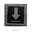
- FIG. 2 is a display effect diagram of displaying an arrow according to the method of borrowing light from adjacent pixels of the prior art.
- FIG. 3 is a pixel effect schematic diagram of displaying an arrow according to the method of borrowing light from adjacent pixels of the prior art.
- FIG. 4 is a pixel schematic diagram of displaying an arrow according to the method of borrowing light from adjacent pixels of the prior art.
- FIG. 5 is a display effect diagram of displaying a word according to the method of borrowing light from adjacent pixels of the prior art.
- FIG. 6 is a pixel effect diagram of displaying a white arrow according to the method of borrowing light from adjacent pixels of the prior art.
- FIG. 7 is a schematic diagram of a display apparatus of embodiments of the present disclosure.
- FIG. 8 is a schematic diagram of a pixel array of a display apparatus of embodiments of the present disclosure.
- FIG. 9 is a schematic diagram of a basic pixel unit of the pixel array as shown in FIG. 8 .
- FIG. 10 is a display effect diagram of displaying an image according to the display method of the second embodiment of the present disclosure.
- FIG. 11 is a local first pixel effect diagram of displaying the image of FIG. 10 according to the display method of the second embodiment of the present disclosure.
- FIG. 12 is a local first pixel effect diagram of displaying the image of FIG. 10 according to the display method of the second embodiment of the present disclosure.
- FIG. 13 is a local first pixel effect diagram of displaying the image of FIG. 10 according to the display method of the second embodiment of the present disclosure.
- FIG. 14 is a first pixel schematic diagram of displaying a red vertical line according to the display method of the second embodiment of the present disclosure.
- FIG. 15 is a second pixel schematic diagram of displaying a red vertical line according to the display method of the second embodiment of the present disclosure.
- FIG. 16 is a third pixel schematic diagram of displaying a red vertical line according to the display method of the second embodiment of the present disclosure.
- FIG. 17 is a pixel schematic diagram of displaying an arrow according to the display method of the first embodiment of the present disclosure.
- FIG. 18 is a display effect diagram of displaying an arrow according to the display method of the first embodiment of the present disclosure.
- FIG. 19 is a pixel effect diagram of displaying an arrow according to the display method of the first embodiment of the present disclosure.
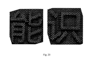
- FIG. 20 is a display effect schematic diagram of displaying a word according to the display method of the first embodiment of the present disclosure.
- FIG. 21 is a pixel effect diagram of displaying a white arrow according to the display method of the first embodiment of the present disclosure.
- a display method (or referred to as a presenting method) of embodiments of the present disclosure can be used in a display apparatus of embodiments of the present disclosure.
- the display apparatus of embodiments of the present disclosure is optionally a display apparatus of a mobile phone, and more preferably, is an AMOLED display apparatus used in the mobile phone.
- FIG. 7 is a schematic diagram of the display device of the present disclosure.
- the display device is an OLED display device 20 .
- the OLED display device 20 at least includes a display unit 200 , a scanning driver 220 and a data driver 230 .
- the OLED display device 20 may also include other devices and/or elements.
- the display unit 200 may include a plurality of pixel points 210 connected to scanning lines (S 1 to Sn), emission control lines (EM 1 to EMn) and data lines (D 1 to Dm). Moreover, one pixel point 210 may have one OLED, and may consist of two sub-pixels which emit light of different colors, e.g., red, green; red, blue; or green, blue.
- the display unit 200 may display an image, so as to correspond to an external first power source (ELVdd) and an external second power source (ELVss).
- the display unit 200 may also display images corresponding to scanning signals provided through the scanning lines S 1 to Sn and generated by the scanning driver 220 , emission control signals provided through the emission control lines EM 1 to EMn and generated by the scanning driver 220 , and data signals provided through the data lines D 1 to Dm and generated by the data driver 230 .
- the scanning driver 220 may generate the scanning signals and the emission control signals.
- the scanning signals generated in the scanning driver 220 may be provided to the scanning lines (S 1 to Sn) sequentially, and the emission control signals generated in the scanning driver 220 may be provided to each one of the emission control lines (EM 1 to EMn) sequentially.
- the scanning signals and the emission control signals may also be respectively provided to the scanning lines S 1 to Sn and the emission control lines EM 1 to EMn non-sequentially.
- the emission control signals may also be generated by an emission control driver.
- the data driver 230 may receive an input signal, e.g., RGB data, and generate a data signal corresponding to the received input signal.
- the data signals generated in the data driver 230 may be provided to the pixel points 210 through the data lines (D 1 to Dm), to be synchronized with the scanning signals.
- the data signals may also be provided to the data lines D 1 to Dm in a manner non-synchronized with the scanning signals.
- a scanning driver provides signals to each of the sub-pixel lines with the same color in the pixel array
- a data driver provides signals to each of the sub-pixel columns with different colors in the pixel array.
- FIG. 9 is a basic pixel unit 30 of the pixel array as shown in FIG. 8 .
- the pixel array is a delta distribution pixel array with a line cycle of 2 and a column cycle of 3.
- the image display method of the present disclosure is not limited to be applied to the pixel array of delta arrangement, but may also be applied to the pixel array of other pixel arrangements.
- sub-pixels in the first line are all red sub-pixels R
- sub-pixels in the second line are all blue sub-pixels B
- sub-pixels in the third line are all green sub-pixels G
- the following arrangements of sub-pixels circulate in this order.
- the display apparatus and display method of the present disclosure are not limited to the above pixel arrangement, and sub-pixels in the first line may also be green sub-pixels or blue sub-pixels.
- one pixel 210 is essentially presented by two sub-pixels.
- the two sub-pixels constituting one pixel 210 have been marked by the ellipse dashed box in FIG. 9 .
- the pixel array shown in FIG. 8 is composed of a plurality of basic pixel units 30 in FIG. 9 repeated along horizontal and vertical directions.
- Each basic pixel unit 30 includes six pixels arranged in two lines and three columns: a first pixel P 11 , a second pixel P 12 and a third pixel P 13 arranged from left to right in a first line, and a fourth pixel P 21 , a fifth pixel P 22 and a sixth pixel P 23 arranged from left to right in a second line.
- the second pixel P 12 to the fifth pixel P 22 are composed of sub-pixels with different colors located in two adjacent horizontal lines respectively, while the first pixel P 11 and the sixth pixel P 23 are composed of sub-pixels with different colors located in the same column but separated by one horizontal line respectively. It can be seen from FIG. 9 that, in the pixel matrix basic unit 30 , the red sub-pixel R 12 , the green sub-pixel G 13 and the blue sub-pixel B 22 are located in pixel spaces of two different pixels.
- two sub-pixels of the first pixel P 11 and the blue sub-pixel B 21 of the fourth pixel P 21 compose the first column in sequence from top to bottom according to a first interval in the vertical direction.
- the blue sub-pixel B 12 of the second pixel P 12 , the red sub-pixel R 21 of the fourth pixel P 21 and the green sub-pixel G 22 of the fifth pixel P 22 compose the second column in sequence from top to bottom according to the first interval in the vertical direction.
- the second column and the first column are separated by a second interval in the horizontal direction.
- the first interval may be less than the height of one sub-pixel, and the second interval may be greater than or equal to zero, so that color mixing will not appear between two sub-pixels composing the same pixel point.
- the display method of embodiments of the present disclosure determines a display gray value of a color in a pixel matrix by calculating the proportion of each color occupied in the shown pixel, and the position and gray value of the color in the original image.
- the data denoting the positions and gray values needed to be displayed of each color in the image to be displayed are firstly acquired.
- the gray values needed to be displayed in pixels P 11 -P 23 are R′ 11 , R′ 12 , R′ 13 , R′ 21 , R′ 22 , R′ 23 .
- each proportion vector has three components, denoting the proportion coefficients of red sub-pixels, green sub-pixels, and blue sub-pixels in the pixel respectively.
- the compensation algorithm used in embodiments of the present disclosure may be called “occupied space algorithm”.
- the display method of embodiments of the present disclosure does not need to calculate the proportion coefficient of sub-pixel in the pixel space accurately, but just checks whether there is sub-pixel of the color within the pixel space of the pixel. If a sub-pixel of the color is entirely located within the pixel space (a concept of area, rather than volume) of the pixel, then the proportion coefficient is set to be “1”. If the sub-pixel of the color is entirely not located within the pixel space of the pixel, then the proportion coefficient is set to be “0”. If the sub-pixel of the color is partly located within the pixel space of the pixel, then the proportion coefficient is set to be “0.5”, no matter a larger part or a smaller part of the sub-pixel is located within the pixel space of the pixel.
- each proportion vectors of six pixels P 11 , P 12 , P 13 , P 21 , P 22 , P 23 of the basic pixel unit 30 as shown in FIG. 9 are respectively: P 11(1,1,0), P 12(0.5,0.5,1), P 13(0.5,0.5,1) P 21(0,0,1), P 22(1,1,0.5), P 23(1,1,0.5)
- the components in the same position of each proportion vector are taken respectively to acquire a proportion matrix.
- the proportion matrix denotes data representing the space proportion of each color occupied in each pixel of the pixel array.
- R is the position and gray value of red color in the pixel array
- R′ is the position and gray value of red color in the original image
- G is the position and gray value of green color in the pixel array
- G′ is the position and gray value of green color in the original image
- B is the position and gray value of blue color in the pixel array
- B′ is the position and gray value of blue color in the original image.
- the display method of the present embodiment does not need to calculate the pixel space percentage of the pixel accurately, but just checks whether there is sub-pixel of the color within the pixel space of the pixel. If a sub-pixel of the color is entirely located within the pixel space (a concept of area, rather than volume) of the pixel, then the proportion coefficient is set to be “1”. If the sub-pixel of the color is entirely not located within the pixel space of the pixel, then the proportion coefficient is set to be “0”.
- the sub-pixel of the color is partly located within the pixel space of the pixel, then it needs to check whether its larger part or smaller part is located within the pixel space of the pixel; if a larger part of sub-pixel of the color is located within pixel space of the pixel, then the proportion coefficient is larger than “0.5” and may be set to be “0.7”; if a smaller part of sub-pixel of the color is located within pixel space of the pixel, then the proportion coefficient is smaller than “0.5” and may be set to be “0.3”.
- the sum of the proportion coefficients in both cases is also 1.
- the proportion vectors representing the proportion occupied by red, green, blue sub-pixel in each pixel respectively are: P 11(1,1,0), P 12(0.7,0.7,1), P 13(0.3,0.3,1) P 21(0,0,1), P 22(1,1,0.7), P 23(1,1,0.3)
- proportion matrixes acquired based on the proportion vectors are:
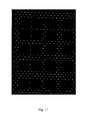
- FIG. 10 width of the border lines is three pixels; widths of the internal horizontal lines are respectively 1-7 pixels which are increased by degrees; widths of the internal longitudinal lines also are respectively 1-7 pixels which are increased by degrees.
- FIGS. 11-13 only take a part of the pixel effect diagram of the image as shown in FIG. 10 . As shown in FIG. 13 , one sub-pixel column with low gray level cannot be displayed. The image of FIG. 10 is displayed in red color, but the present disclosure is not limited to this. The present disclosure has the same effect when displaying in blue or green color. Therefore, red color is just taken as an example to make illustration herein.
- FIGS. 11-13 there are three different display manners for the longitudinal lines with one pixel width when using the display method of the second embodiment of the present disclosure. Because the horizontal pixel cycle of the pixel array shown in FIG. 9 is three columns, it may display three different kinds of longitudinal lines. Taking the red sub-pixel as an example, three different kinds of longitudinal lines are shown in FIGS. 14-16 respectively.
- red sub-pixels are lit every other pixel line, and it is displayed in one-hundred percent of gray value of the red color needed to be displayed.
- the second kind of longitudinal line when displaying the second kind of longitudinal line, it is displayed by two red sub-pixel columns respectively, in which one column of red sub-pixels are displayed in one-hundred percent of gray value of the red color needed to be displayed, and according to the display method of the second embodiment, the other column of red sub-pixels (the third column from left in the figure) are displayed in seventy percent of gray value of the red color needed to be displayed, i.e., the gray value actually displayed is 0.7 times of the gray value of red color in the original image.
- the third kind of longitudinal line when displaying the third kind of longitudinal line, it is displayed by two red sub-pixel columns respectively, in which one column of red sub-pixels are displayed in one-hundred percent of gray value of the red color needed to be displayed, and according to the display method of the second embodiment, the other column of red sub-pixels (the third column from left in the figure) are displayed in thirty percent of gray value of the red color needed to be displayed, i.e., the gray value actually displayed is 0.3 times of the gray value of red color in the original image.
- the two display manners both display in the same sub-pixel line.
- the number of lines of sub-pixels actually emitting light equals to the number of pixels included in the width direction of the horizontal line. For example, when the horizontal line with width of four pixels is displayed, the sub-pixels actually emitting light are in four lines. While when the longitudinal line is displayed, in most cases, the number of lines of sub-pixels actually emitting light does not equal to the number of pixels included in the width direction of the longitudinal line.
- the display method of the first embodiment of the present disclosure when the display method of the first embodiment of the present disclosure is applied to display a green arrow, most of the green sub-pixels in the region covered by the arrow are displayed in one-hundred percent of gray value of the green color needed to be displayed. Only in the case of several boundaries, a few green sub-pixels are displayed in fifty percent of gray value of the green color needed to be displayed, which include the green sub-pixel G 0101 in the pixel of the first line and first column, the green sub-pixel G 0707 in the pixel of the seventh line and seventh column, and the green sub-pixel G 0516 in the pixel of the fifth line and sixteenth column.
- FIG. 18 is a display effect diagram of displaying an arrow according to the display method of the first embodiment of the present disclosure.
- FIG. 19 is a pixel effect diagram of displaying an arrow according to the display method of the first embodiment of the present disclosure.
- FIG. 20 is a display effect schematic diagram of displaying a word according to the display method of the first embodiment of the present disclosure.
- FIG. 21 is a pixel effect diagram of displaying a white arrow according to the display method of the first embodiment of the present disclosure.
- the technical effect of the display method of the present disclosure with respect to the display method of the prior art can be known by comparing FIGS. 18-21 with FIGS. 2, 3, 5 and 6 respectively.
- a suitable display method may be selected from the two embodiments respectively directing at different situations of display apparatus's displaying (for example, an application mainly displayed in words, and an application mainly displayed in images), thus obtaining satisfactory display effects.
- the display apparatus includes: a substrate, an organic light emitting diode and a driver.
- the substrate has a pixel region and a non-pixel region; the organic light emitting diode is located in the pixel region and includes a first electrode, an organic thin layer and a second electrode; the driver is used to drive the organic light emitting diode.
- the pixel array in the pixel region of the display apparatus according to embodiments of the present disclosure may be a pixel array as shown in FIG. 8 , but not limited thereto.
- the driver is used to drive the organic light emitting diode, and the driver includes an input unit, a sub-pixel display unit and an output unit.
- the image display methods of the above embodiments of the present disclosure are implemented in the sub-pixel display unit.
- the input unit is used for inputting an image signal that denotes an image to be presented on the display apparatus.
- the sub-pixel color rendering unit is used for acquiring the image data denoting positions and gray values needed to be displayed of each color in the image respectively; further acquiring the proportion matrix denoting the space proportions of each color occupied in each pixel of the pixel array respectively; for each of the sub-pixels contained in each of the pixels, acquiring the sub-pixel display data according to the image data and the proportion matrix, the sub-pixel display data denoting the display gray value of each of the sub-pixels of the pixel in the pixel array.
- the output unit is used for generating a plurality of electrical signals according to the sub-pixel display data, and outputting the plurality of signals to the display apparatus to display the image.
Landscapes
- Engineering & Computer Science (AREA)
- Physics & Mathematics (AREA)
- Computer Hardware Design (AREA)
- General Physics & Mathematics (AREA)
- Theoretical Computer Science (AREA)
- Control Of Indicators Other Than Cathode Ray Tubes (AREA)
- Electroluminescent Light Sources (AREA)
- Control Of El Displays (AREA)
- Devices For Indicating Variable Information By Combining Individual Elements (AREA)
Abstract
Description
R″(2,2)=R′(2,1)+½R′(2,3)
P11(1,1,0),P12(0.5,0.5,1),P13(0.5,0.5,1)
P21(0,0,1),P22(1,1,0.5),P23(1,1,0.5)
R11=R′11;R12=0.5R′12+0.5R′13
R21=R′22;R23=R′23
G11=G′11;G13=0.5G′12+0.5G′13
G22=G′22;G23=G′23
B12=B′12;B13=B′13
B21=B′21;B22=0.5B′22+0.5B′23
P11(1,1,0),P12(0.7,0.7,1),P13(0.3,0.3,1)
P21(0,0,1),P22(1,1,0.7),P23(1,1,0.3)
R11=R′11;R12=0.7R′12+0.3R′13
R21=R′22;R23=R′23
G11=G′11;G13=0.7G′12+0.3G′13
G22=G′22;G23=G′23
B12=B′12;B13=B′13
B21=B′21;B22=0.7B′22+0.3B′23
Claims (16)
Applications Claiming Priority (3)
| Application Number | Priority Date | Filing Date | Title |
|---|---|---|---|
| CN201510142031.5A CN106157876B (en) | 2015-03-27 | 2015-03-27 | The display methods and display of display image |
| CN201510142031.5 | 2015-03-27 | ||
| CN201510142031 | 2015-03-27 |
Publications (2)
| Publication Number | Publication Date |
|---|---|
| US20160314735A1 US20160314735A1 (en) | 2016-10-27 |
| US10083648B2 true US10083648B2 (en) | 2018-09-25 |
Family
ID=55637276
Family Applications (1)
| Application Number | Title | Priority Date | Filing Date |
|---|---|---|---|
| US15/081,543 Active 2036-05-21 US10083648B2 (en) | 2015-03-27 | 2016-03-25 | Image display method and display apparatus |
Country Status (4)
| Country | Link |
|---|---|
| US (1) | US10083648B2 (en) |
| EP (1) | EP3073478B1 (en) |
| JP (1) | JP6934283B2 (en) |
| CN (1) | CN106157876B (en) |
Families Citing this family (5)
| Publication number | Priority date | Publication date | Assignee | Title |
|---|---|---|---|---|
| CN106530994B (en) * | 2016-12-30 | 2018-12-28 | 上海天马有机发光显示技术有限公司 | A kind of method and display device for eliminating display figure coloured silk side |
| CN106898291B (en) * | 2017-04-28 | 2019-08-02 | 武汉华星光电技术有限公司 | The driving method and driving device of display panel |
| CN107331341B (en) * | 2017-08-10 | 2020-11-03 | 武汉华星光电技术有限公司 | Sub-pixel rendering method and system |
| JP7152917B2 (en) * | 2018-01-31 | 2022-10-13 | Tianma Japan株式会社 | Display device and method for converting relative luminance data of image frame into relative luminance data of display panel |
| KR102314074B1 (en) * | 2019-10-31 | 2021-10-19 | 칩원 테크놀로지(베이징) 컴퍼니 리미티드 | Sub-pixel rendering method, driving chip and display device |
Citations (10)
| Publication number | Priority date | Publication date | Assignee | Title |
|---|---|---|---|---|
| GB2320790A (en) | 1996-12-30 | 1998-07-01 | Hyundai Electronics Ind | Offset pixel arrangement |
| US20020140655A1 (en) | 2001-04-03 | 2002-10-03 | Wei-Chen Liang | Pixel driving module of liquid crystal display |
| US20100096988A1 (en) * | 2008-10-17 | 2010-04-22 | Seiko Epson Corporation | Organic electroluminescent device, method for producing organic electroluminescent device, and electronic apparatus |
| US20130293526A1 (en) | 2012-05-04 | 2013-11-07 | Samsung Display Co., Ltd. | Display device and method of operating the same |
| CN103745684A (en) | 2013-11-13 | 2014-04-23 | 上海和辉光电有限公司 | Pixel array, method for presenting image on display, and display |
| CN103927946A (en) | 2014-03-25 | 2014-07-16 | 京东方科技集团股份有限公司 | Display method |
| CN104201192A (en) | 2014-09-16 | 2014-12-10 | 上海和辉光电有限公司 | Display pixel structure, metal mask and OLED display |
| CN104319283A (en) | 2014-10-27 | 2015-01-28 | 京东方科技集团股份有限公司 | Organic electroluminescence display component, drive method thereof and display device |
| US20150029208A1 (en) | 2013-07-25 | 2015-01-29 | Samsung Display Co., Ltd. | Pixel array structure and display apparatus including the same |
| CN104332486A (en) | 2014-10-29 | 2015-02-04 | 上海和辉光电有限公司 | OLED (Organic Light Emitting Diode) pixel arrangement structure |
Family Cites Families (5)
| Publication number | Priority date | Publication date | Assignee | Title |
|---|---|---|---|---|
| US7123277B2 (en) * | 2001-05-09 | 2006-10-17 | Clairvoyante, Inc. | Conversion of a sub-pixel format data to another sub-pixel data format |
| KR100436715B1 (en) * | 2002-11-04 | 2004-06-22 | 삼성에스디아이 주식회사 | Method of fast processing image data for improving reproducibility of image |
| US20080001525A1 (en) * | 2006-06-30 | 2008-01-03 | Au Optronics Corporation | Arrangements of color pixels for full color OLED |
| JP5236422B2 (en) * | 2008-10-16 | 2013-07-17 | シャープ株式会社 | Transmission type liquid crystal display device |
| JP5176993B2 (en) * | 2009-02-02 | 2013-04-03 | セイコーエプソン株式会社 | Electro-optical device and electronic apparatus |
-
2015
- 2015-03-27 CN CN201510142031.5A patent/CN106157876B/en active Active
- 2015-10-20 JP JP2015206150A patent/JP6934283B2/en active Active
-
2016
- 2016-03-25 US US15/081,543 patent/US10083648B2/en active Active
- 2016-03-29 EP EP16162576.9A patent/EP3073478B1/en active Active
Patent Citations (14)
| Publication number | Priority date | Publication date | Assignee | Title |
|---|---|---|---|---|
| GB2320790A (en) | 1996-12-30 | 1998-07-01 | Hyundai Electronics Ind | Offset pixel arrangement |
| US20020140655A1 (en) | 2001-04-03 | 2002-10-03 | Wei-Chen Liang | Pixel driving module of liquid crystal display |
| US20100096988A1 (en) * | 2008-10-17 | 2010-04-22 | Seiko Epson Corporation | Organic electroluminescent device, method for producing organic electroluminescent device, and electronic apparatus |
| CN101727828A (en) | 2008-10-17 | 2010-06-09 | 精工爱普生株式会社 | Organic EL device, method for manufacturing organic EL device, and electronic apparatus |
| US20130293526A1 (en) | 2012-05-04 | 2013-11-07 | Samsung Display Co., Ltd. | Display device and method of operating the same |
| US20150029208A1 (en) | 2013-07-25 | 2015-01-29 | Samsung Display Co., Ltd. | Pixel array structure and display apparatus including the same |
| CN104347668A (en) | 2013-07-25 | 2015-02-11 | 三星显示有限公司 | Display apparatus |
| CN103745684A (en) | 2013-11-13 | 2014-04-23 | 上海和辉光电有限公司 | Pixel array, method for presenting image on display, and display |
| US20150130868A1 (en) | 2013-11-13 | 2015-05-14 | Everdisplay Optronics (Shanghai) Limited | Pixel array, display and method for rendering image on a display |
| CN103927946A (en) | 2014-03-25 | 2014-07-16 | 京东方科技集团股份有限公司 | Display method |
| US20160300519A1 (en) * | 2014-03-25 | 2016-10-13 | Boe Techology Group Co., Ltd. | Display Method, Display Panel and Display Device |
| CN104201192A (en) | 2014-09-16 | 2014-12-10 | 上海和辉光电有限公司 | Display pixel structure, metal mask and OLED display |
| CN104319283A (en) | 2014-10-27 | 2015-01-28 | 京东方科技集团股份有限公司 | Organic electroluminescence display component, drive method thereof and display device |
| CN104332486A (en) | 2014-10-29 | 2015-02-04 | 上海和辉光电有限公司 | OLED (Organic Light Emitting Diode) pixel arrangement structure |
Non-Patent Citations (2)
| Title |
|---|
| The 1st office action issued in the counterpart CN application No. 201510142031.5 dated Feb. 27, 2018, by the SIPO. |
| The Extended European Search Report issued by the EPO, dated Jul. 26, 2016. |
Also Published As
| Publication number | Publication date |
|---|---|
| JP6934283B2 (en) | 2021-09-15 |
| JP2016186629A (en) | 2016-10-27 |
| EP3073478B1 (en) | 2021-04-28 |
| CN106157876A (en) | 2016-11-23 |
| EP3073478A1 (en) | 2016-09-28 |
| US20160314735A1 (en) | 2016-10-27 |
| CN106157876B (en) | 2019-04-23 |
Similar Documents
| Publication | Publication Date | Title |
|---|---|---|
| US11037523B2 (en) | Display method of display panel that uses different display algorithms for different display areas, display panel and display device | |
| US9576519B2 (en) | Display method and display device | |
| US9620050B2 (en) | Display method and display device | |
| US9875684B2 (en) | Array substrate, its driving method, and display device | |
| US9786210B2 (en) | Pixel array composed of pixel units, display and method for rendering image on a display | |
| US9589492B2 (en) | Pixel array, display and method for presenting image on the display | |
| US9875682B2 (en) | Display method and display panel | |
| US10140902B2 (en) | Display method and display panel | |
| CN102622981B (en) | Method and driver for displaying sub-pixels for color display with triangular structure | |
| US10083648B2 (en) | Image display method and display apparatus | |
| CN105185244B (en) | A kind of dot structure, display panel and display device | |
| US9640103B2 (en) | Apparatus for converting data and display apparatus using the same | |
| US20160300519A1 (en) | Display Method, Display Panel and Display Device | |
| CN114267291B (en) | Gray scale data determination method, device, equipment and screen driving plate | |
| US10650718B2 (en) | Method and display device for sub -pixel rendering | |
| CN109308868B (en) | Display panel driving method and system and display device | |
| CN111383569A (en) | Image compensation method and image processing circuit | |
| CN116095398B (en) | Sub-pixel rendering method and system of RGBG display panel | |
| CN117437885A (en) | Method and device for voltage drop compensation of display screen | |
| KR102520697B1 (en) | Display device using subpixel rendering and image processing method thereof | |
| KR102090605B1 (en) | Data converting circuit and display apparatus using the same | |
| US20210043136A1 (en) | Driving method for display substrate, driving circuit and display device | |
| JP6593899B2 (en) | Method and system for improving contrast ratio of OLED display panel | |
| JP2018531425A6 (en) | Method and system for improving contrast ratio of OLED display panel | |
| CN108269535B (en) | Display method and display device |
Legal Events
| Date | Code | Title | Description |
|---|---|---|---|
| AS | Assignment |
Owner name: EVERDISPLAY OPTRONICS (SHANGHAI) LIMITED, CHINA Free format text: ASSIGNMENT OF ASSIGNORS INTEREST;ASSIGNOR:FENG, YU-HSIUNG;REEL/FRAME:038105/0109 Effective date: 20160318 |
|
| STCF | Information on status: patent grant |
Free format text: PATENTED CASE |
|
| AS | Assignment |
Owner name: EVERDISPLAY OPTRONICS (SHANGHAI) CO., LTD., CHINA Free format text: CORRECTIVE ASSIGNMENT TO CORRECT THE CORRECT RECEIVING PARTY DATA PREVIOUSLY RECORDED AT REEL: 038105 FRAME: 0109. ASSIGNOR(S) HEREBY CONFIRMS THE ASSIGNMENT;ASSIGNOR:FENG, YU-HSIUNG;REEL/FRAME:053377/0973 Effective date: 20160318 |
|
| MAFP | Maintenance fee payment |
Free format text: PAYMENT OF MAINTENANCE FEE, 4TH YEAR, LARGE ENTITY (ORIGINAL EVENT CODE: M1551); ENTITY STATUS OF PATENT OWNER: LARGE ENTITY Year of fee payment: 4 |