US10079412B2 - Electrochemical electricity storage cell - Google Patents
Electrochemical electricity storage cell Download PDFInfo
- Publication number
- US10079412B2 US10079412B2 US14/437,260 US201314437260A US10079412B2 US 10079412 B2 US10079412 B2 US 10079412B2 US 201314437260 A US201314437260 A US 201314437260A US 10079412 B2 US10079412 B2 US 10079412B2
- Authority
- US
- United States
- Prior art keywords
- electrodes
- electrochemical cell
- casing
- positive
- contact element
- Prior art date
- Legal status (The legal status is an assumption and is not a legal conclusion. Google has not performed a legal analysis and makes no representation as to the accuracy of the status listed.)
- Active, expires
Links
Images


Classifications
-
- H—ELECTRICITY
- H01—ELECTRIC ELEMENTS
- H01M—PROCESSES OR MEANS, e.g. BATTERIES, FOR THE DIRECT CONVERSION OF CHEMICAL ENERGY INTO ELECTRICAL ENERGY
- H01M10/00—Secondary cells; Manufacture thereof
- H01M10/60—Heating or cooling; Temperature control
- H01M10/61—Types of temperature control
- H01M10/613—Cooling or keeping cold
-
- H—ELECTRICITY
- H01—ELECTRIC ELEMENTS
- H01M—PROCESSES OR MEANS, e.g. BATTERIES, FOR THE DIRECT CONVERSION OF CHEMICAL ENERGY INTO ELECTRICAL ENERGY
- H01M10/00—Secondary cells; Manufacture thereof
- H01M10/04—Construction or manufacture in general
- H01M10/0413—Large-sized flat cells or batteries for motive or stationary systems with plate-like electrodes
-
- H—ELECTRICITY
- H01—ELECTRIC ELEMENTS
- H01M—PROCESSES OR MEANS, e.g. BATTERIES, FOR THE DIRECT CONVERSION OF CHEMICAL ENERGY INTO ELECTRICAL ENERGY
- H01M10/00—Secondary cells; Manufacture thereof
- H01M10/60—Heating or cooling; Temperature control
- H01M10/62—Heating or cooling; Temperature control specially adapted for specific applications
- H01M10/625—Vehicles
-
- H—ELECTRICITY
- H01—ELECTRIC ELEMENTS
- H01M—PROCESSES OR MEANS, e.g. BATTERIES, FOR THE DIRECT CONVERSION OF CHEMICAL ENERGY INTO ELECTRICAL ENERGY
- H01M10/00—Secondary cells; Manufacture thereof
- H01M10/60—Heating or cooling; Temperature control
- H01M10/65—Means for temperature control structurally associated with the cells
- H01M10/654—Means for temperature control structurally associated with the cells located inside the innermost case of the cells, e.g. mandrels, electrodes or electrolytes
-
- H—ELECTRICITY
- H01—ELECTRIC ELEMENTS
- H01M—PROCESSES OR MEANS, e.g. BATTERIES, FOR THE DIRECT CONVERSION OF CHEMICAL ENERGY INTO ELECTRICAL ENERGY
- H01M10/00—Secondary cells; Manufacture thereof
- H01M10/60—Heating or cooling; Temperature control
- H01M10/65—Means for temperature control structurally associated with the cells
- H01M10/655—Solid structures for heat exchange or heat conduction
- H01M10/6552—Closed pipes transferring heat by thermal conductivity or phase transition, e.g. heat pipes
-
- H01M2/06—
-
- H01M2/305—
-
- H—ELECTRICITY
- H01—ELECTRIC ELEMENTS
- H01M—PROCESSES OR MEANS, e.g. BATTERIES, FOR THE DIRECT CONVERSION OF CHEMICAL ENERGY INTO ELECTRICAL ENERGY
- H01M50/00—Constructional details or processes of manufacture of the non-active parts of electrochemical cells other than fuel cells, e.g. hybrid cells
- H01M50/50—Current conducting connections for cells or batteries
- H01M50/543—Terminals
- H01M50/547—Terminals characterised by the disposition of the terminals on the cells
- H01M50/548—Terminals characterised by the disposition of the terminals on the cells on opposite sides of the cell
-
- H—ELECTRICITY
- H01—ELECTRIC ELEMENTS
- H01M—PROCESSES OR MEANS, e.g. BATTERIES, FOR THE DIRECT CONVERSION OF CHEMICAL ENERGY INTO ELECTRICAL ENERGY
- H01M2220/00—Batteries for particular applications
- H01M2220/20—Batteries in motive systems, e.g. vehicle, ship, plane
-
- Y—GENERAL TAGGING OF NEW TECHNOLOGICAL DEVELOPMENTS; GENERAL TAGGING OF CROSS-SECTIONAL TECHNOLOGIES SPANNING OVER SEVERAL SECTIONS OF THE IPC; TECHNICAL SUBJECTS COVERED BY FORMER USPC CROSS-REFERENCE ART COLLECTIONS [XRACs] AND DIGESTS
- Y02—TECHNOLOGIES OR APPLICATIONS FOR MITIGATION OR ADAPTATION AGAINST CLIMATE CHANGE
- Y02E—REDUCTION OF GREENHOUSE GAS [GHG] EMISSIONS, RELATED TO ENERGY GENERATION, TRANSMISSION OR DISTRIBUTION
- Y02E60/00—Enabling technologies; Technologies with a potential or indirect contribution to GHG emissions mitigation
- Y02E60/10—Energy storage using batteries
-
- Y—GENERAL TAGGING OF NEW TECHNOLOGICAL DEVELOPMENTS; GENERAL TAGGING OF CROSS-SECTIONAL TECHNOLOGIES SPANNING OVER SEVERAL SECTIONS OF THE IPC; TECHNICAL SUBJECTS COVERED BY FORMER USPC CROSS-REFERENCE ART COLLECTIONS [XRACs] AND DIGESTS
- Y02—TECHNOLOGIES OR APPLICATIONS FOR MITIGATION OR ADAPTATION AGAINST CLIMATE CHANGE
- Y02P—CLIMATE CHANGE MITIGATION TECHNOLOGIES IN THE PRODUCTION OR PROCESSING OF GOODS
- Y02P70/00—Climate change mitigation technologies in the production process for final industrial or consumer products
- Y02P70/50—Manufacturing or production processes characterised by the final manufactured product
Definitions
- the present invention relates to the field of electrochemical cells for storing electricity, in particular for motor vehicle batteries, although the invention is not limited to this field of application.
- an electrochemical cell for storing electricity consists of one or more positive electrodes stacked alternately with one or more negative electrodes, as well as one or more separators so as to separate the positive and negative electrodes, and a leaktight casing which may be flexible, as in the case of a “pouch cell”, or rigid for a “hard casing” cell.
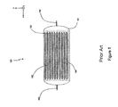
- an electrochemical cell 100 comprising a casing 101 in which a plurality of positive electrodes 102 , connected to a positive terminal 105 , are arranged alternately with negative electrodes 103 connected to a negative terminal 106 .
- Separators 104 impregnated with electrolyte are formed between each positive and negative electrode. These separators, as well as the positive and negative electrodes, have a substantially rectangular profile and are placed in a plane parallel to the (x,y) plane, which corresponds to the longitudinal plane of the cell.
- the cooling is not optimal.
- the internal structure of the cell consists of a stack of negative electrodes and positive electrodes separated by separators impregnated with electrolyte.
- the thermal conductivity toward the surface of the cell will be limited by the thermal conductivity of the various materials, for example separators made of polyolefin (polyethylene, polypropylene) with a thermal conductivity of less than 1 watt per meter per kelvin, electrodes made of aluminum or copper with a conductivity of more than 100 watts per meter per kelvin, and by the thermal resistances at the interfaces between the various electrodes and/or separators.
- Cooling techniques using means for circulating air at the surface of the cell are also known.
- a drawback of such a cooling technique is that it uses means having significant size as well as a relatively high cost, which is not satisfactory either.
- the maintenance cost of such a technique also proves relatively high.
- the objects of the invention are, in particular, to overcome at least some of the drawbacks of the prior art.
- an electrochemical cell for storing electricity comprising a casing in which the following are arranged:
- the electrochemical cell furthermore comprises at least one contact element arranged in contact with the positive and negative electrodes and the casing.
- This contact element makes it possible to optimize the contact between the casing and the positive and negative electrodes, and thus to increase the heat exchange between the edges of each of the electrodes and of the separator with the casing. Consequently, the heat exchange with the outside of the cell is promoted, which improves the cooling in comparison with the techniques of the prior art.
- the invention provides a novel and inventive approach making it possible to optimize the contact surface between the electrodes and the casing and thus to improve the cooling of the electrochemical cell by removing heat over the entire contact zone between the casing and the electrodes, and more particularly at the edges.
- the heat exchange is facilitated when it takes place through the edges of the cell rather than at the surface.
- the heat exchange is limited by the thermal conductivity of the electrodes and of the separators. The invention makes it possible to overcome these constraints by allowing optimal heat exchange via the edges of the electrodes and of the separators.
- the contact element comprises at least one heat pipe, of which a first end is connected to the contact element and a second end is formed outside the electrochemical cell.
- the casing of the cell is made either of a flexible material or of a rigid material.
- a flexible material will allow a certain flexibility of the electrochemical cell and will also allow the casing to adopt substantially the shape of the electrodes.
- a rigid material will be able to form a protective casing for the cells.
- the contact element may be made either of polymer or of elastomer.
- the positive electrodes and the negative electrodes are of substantially rectangular shape.
- the contact element may be formed either over the width or over the length of the positive and negative electrodes, between the edges of these electrodes and the casing.
- the invention also relates to a battery comprising at least one electrochemical cell, and to a corresponding vehicle.
- FIG. 1 is a view in section along the (x,z) plane of an electrochemical cell of the prior art
- FIG. 2 is a view in section along the (x,z) plane of an electrochemical cell according to a first embodiment of the invention
- FIG. 3 is a view in section along the (x,z) plane of an electrochemical cell according to a second embodiment of the invention.
- FIG. 4 is a view in section along the (x,z) plane of a motor vehicle battery using a plurality of electrochemical cells according to the second embodiment.
- FIG. 5 is a graph presenting the variation in temperature as a function of time for a cell of the prior art and for a cell according to the invention.
- the x axis is defined as being the longitudinal direction of a cell according to the invention.
- the (x,y) plane corresponds to the plane of the electrodes while the (x,z) plane corresponds to a transverse plane orthogonal to the (x,y) plane.
- a first embodiment of the invention is now presented with reference to FIG. 2 .
- the electrochemical cell comprises a casing 3 which, in this example, is a flexible casing made of polymer.
- a plurality of positive electrodes 21 in alternation with negative electrodes 22 are arranged in this casing 3 .
- a separator 23 Inserted between each of the positive and negative electrodes, there is a separator 23 impregnated with an electrolyte in a known way, thus making it possible to conduct the electric current between the positive 21 and negative 22 electrodes.
- the assembly 2 formed by the positive electrodes, the negative electrodes and the separators has a substantially rectangular profile and is formed in a substantially horizontal plane parallel to the (x,y) plane.
- the electrochemical cell 1 also comprises contact elements 4 a , 4 b arranged at the ends of the positive and negative electrodes along the x direction, that is to say over the width of the electrodes, between the assembly 2 and the casing 3 .
- These contact elements which in this example are in the form of a foam consisting of a polymer such as polyethylene terephthalate (PET), make it possible to optimize the contact between the electrodes and the casing and thus to increase the thermal conductivity at the interface. All the heat, or at the very least a large part of it, will therefore be dissipated at the ends of the (x,y) plane, which corresponds to the edges of the electrodes.
- PET polyethylene terephthalate
- contact elements which are adhesively bonded to the package in order to reduce the risk of these elements being detached during the lifetime of the cell may be envisioned.
- An embodiment in which the contact elements are premolded in the casing in order to improve the contact with each of the electrodes may also be envisioned. It is also possible to provide other embodiments in which the contact elements are made of elastomer, or another polymer such as polypropylene (PP) or polyethylene (PE).
- contact elements used at the ends of the negative and positive electrodes, but in the y direction, i.e. over the length of the electrodes, may also be envisioned.
- An embodiment in which a single contact element is used, for example at one of the ends of the electrodes, along the x or y direction, may furthermore be envisioned.
- the cell has only one positive electrode and one negative electrode, which are separated by a separator, could be provided.
- the casing is rigid and made of other materials, such as metal.
- the contact elements are placed at the ends of the electrodes along the x direction, corresponding to the longitudinal direction of the cell, between the electrodes and the casing.
- FIG. 3 A view in section of an electrochemical cell according to a second embodiment of the invention is now presented with reference to FIG. 3 .
- the electrochemical cell 1 furthermore comprises a heat pipe 7 , of which a first end 71 is connected to the contact element 4 a and a second end 72 is formed outside the electrochemical cell 1 .
- Installing this heat pipe 7 inside the cell makes it possible to limit the number of physical barriers by creating a “bridge” between the inside of the cell and the outside. This thus promotes the dynamics of the thermal dissipation inside the cell.
- FIG. 4 A view in section along a (x,z) plane of a motor vehicle battery, that is to say a cross section, using a plurality of electrochemical cells 1 according to the invention, each comprising a heat pipe, is now presented with reference to FIG. 4 .
- the battery A comprises three electrochemical cells 1 a , 1 b , 1 c implemented according to the second embodiment presented above. These three electrochemical cells are stacked along the z direction, corresponding to the direction perpendicular to the plane of the electrodes, which, in this example, are rectangular. They are placed in a compartment 30 forming the housing of the battery A, this housing furthermore comprising a positive terminal 50 and a negative terminal 60 .
- batteries comprising one or more cells adopting different configurations may of course be envisioned.
- a battery comprising a plurality of rows of cells stacked along the y axis may be envisioned.
- the cells are for example placed end-to-end along the x axis, which corresponds to the longitudinal axis of the cells, may also be provided.
- a graph showing the variation of the internal temperature (ordinate axis) as a function of time (abscissa axis) for a cell of the prior art and for a cell according to the invention is now presented with reference to FIG. 5 .
- This graph G comprises a curve J presenting the variation of the internal temperature of a cell of the prior art as a function of the operating time.
- the curve J rises rapidly during the first hour then rises more slowly during the next thirty minutes, before reaching a maximum of 40 degrees.
- the temperature oscillates between 38.5 degrees and 40 degrees Celsius.
- a second curve I of the graph G presents the variation of the internal temperature of an electrochemical cell according to the invention as a function of the operating time.
- curve I rises slowly during the first 45 minutes then stabilizes at a maximum value of 36 degrees.
- the internal temperature will oscillate between 34.5 and 36 degrees Celsius.
- a temperature difference of about 4 degrees Celsius is therefore observed between a cell of the prior art and a cell according to the invention, which, by virtue of the cooling means employed, therefore has a relatively lower internal temperature.
Landscapes
- Chemical & Material Sciences (AREA)
- Chemical Kinetics & Catalysis (AREA)
- Electrochemistry (AREA)
- General Chemical & Material Sciences (AREA)
- Engineering & Computer Science (AREA)
- Manufacturing & Machinery (AREA)
- Secondary Cells (AREA)
- Battery Mounting, Suspending (AREA)
Applications Claiming Priority (3)
| Application Number | Priority Date | Filing Date | Title |
|---|---|---|---|
| FR1260043 | 2012-10-22 | ||
| FR1260043A FR2997234B1 (fr) | 2012-10-22 | 2012-10-22 | Cellule electrochimique de stockage d'electricite. |
| PCT/FR2013/052434 WO2014064360A1 (fr) | 2012-10-22 | 2013-10-11 | Cellule electrochimique de stockage d'electricite |
Publications (2)
| Publication Number | Publication Date |
|---|---|
| US20150325888A1 US20150325888A1 (en) | 2015-11-12 |
| US10079412B2 true US10079412B2 (en) | 2018-09-18 |
Family
ID=47598902
Family Applications (1)
| Application Number | Title | Priority Date | Filing Date |
|---|---|---|---|
| US14/437,260 Active 2035-05-31 US10079412B2 (en) | 2012-10-22 | 2013-10-11 | Electrochemical electricity storage cell |
Country Status (6)
| Country | Link |
|---|---|
| US (1) | US10079412B2 (fr) |
| EP (1) | EP2909888A1 (fr) |
| KR (1) | KR102102714B1 (fr) |
| CN (1) | CN104854755B (fr) |
| FR (1) | FR2997234B1 (fr) |
| WO (1) | WO2014064360A1 (fr) |
Families Citing this family (2)
| Publication number | Priority date | Publication date | Assignee | Title |
|---|---|---|---|---|
| FR3030121B1 (fr) * | 2014-12-16 | 2017-01-20 | Commissariat Energie Atomique | Accumulateur au lithium avec emballage isolant thermiquement a deux couches et avec caloduc pour la gestion thermique |
| US20230060247A1 (en) * | 2021-08-25 | 2023-03-02 | GM Global Technology Operations LLC | Battery including thermally conductive filler material with thermal runaway containment function |
Citations (9)
| Publication number | Priority date | Publication date | Assignee | Title |
|---|---|---|---|---|
| US6010800A (en) * | 1998-06-17 | 2000-01-04 | Hughes Electronics Corporation | Method and apparatus for transferring heat generated by a battery |
| US6767666B2 (en) * | 2001-03-21 | 2004-07-27 | Ngk Insulators, Ltd. | Lithium secondary cell and lithium secondary cell connecting structure |
| JP2006172870A (ja) | 2004-12-15 | 2006-06-29 | Toyota Motor Corp | 電池と組電池 |
| WO2012029944A1 (fr) | 2010-09-03 | 2012-03-08 | 三菱重工業株式会社 | Batterie |
| US20120164492A1 (en) | 2009-04-08 | 2012-06-28 | Li-Tec Battery Gmbh | Accumulator with extended durability |
| WO2012167022A1 (fr) | 2011-06-03 | 2012-12-06 | Johnson Controls Technology Llc | Cellules électrochimiques comprenant des systèmes de collecte et de transfert de chaleur améliorés |
| US20140349145A1 (en) * | 2013-05-23 | 2014-11-27 | Elwha Llc | Fast thermal dumping for batteries |
| US9666907B2 (en) * | 2013-09-03 | 2017-05-30 | Ut-Battelle, Llc | Thermal management for high-capacity large format Li-ion batteries |
| US9689624B2 (en) * | 2011-11-18 | 2017-06-27 | GM Global Technology Operations LLC | Method for mitigating thermal propagation of batteries using heat pipes |
Family Cites Families (4)
| Publication number | Priority date | Publication date | Assignee | Title |
|---|---|---|---|---|
| KR100325873B1 (ko) * | 2000-04-12 | 2002-03-07 | 김순택 | 폴리머로 피복된 탭을 구비하는 리튬 이온 폴리머 전지 |
| DE102009037850A1 (de) * | 2009-08-18 | 2011-02-24 | Li-Tec Battery Gmbh | Elektrochemische Zelle |
| DE102009048237A1 (de) * | 2009-10-05 | 2011-04-21 | Li-Tec Battery Gmbh | Elektrochemische Zelle und Verfahren zur Herstellung einer solchen Zelle |
| US9196938B2 (en) | 2010-07-06 | 2015-11-24 | Samsung Sdi Co., Ltd. | Battery module |
-
2012
- 2012-10-22 FR FR1260043A patent/FR2997234B1/fr active Active
-
2013
- 2013-10-11 CN CN201380064437.5A patent/CN104854755B/zh active Active
- 2013-10-11 US US14/437,260 patent/US10079412B2/en active Active
- 2013-10-11 WO PCT/FR2013/052434 patent/WO2014064360A1/fr active Application Filing
- 2013-10-11 KR KR1020157013457A patent/KR102102714B1/ko active IP Right Grant
- 2013-10-11 EP EP13785546.6A patent/EP2909888A1/fr not_active Withdrawn
Patent Citations (11)
| Publication number | Priority date | Publication date | Assignee | Title |
|---|---|---|---|---|
| US6010800A (en) * | 1998-06-17 | 2000-01-04 | Hughes Electronics Corporation | Method and apparatus for transferring heat generated by a battery |
| US6767666B2 (en) * | 2001-03-21 | 2004-07-27 | Ngk Insulators, Ltd. | Lithium secondary cell and lithium secondary cell connecting structure |
| JP2006172870A (ja) | 2004-12-15 | 2006-06-29 | Toyota Motor Corp | 電池と組電池 |
| US20120164492A1 (en) | 2009-04-08 | 2012-06-28 | Li-Tec Battery Gmbh | Accumulator with extended durability |
| WO2012029944A1 (fr) | 2010-09-03 | 2012-03-08 | 三菱重工業株式会社 | Batterie |
| US20130295430A1 (en) | 2010-09-03 | 2013-11-07 | Mitsubishi Heavy Industries, Ltd. | Battery |
| WO2012167022A1 (fr) | 2011-06-03 | 2012-12-06 | Johnson Controls Technology Llc | Cellules électrochimiques comprenant des systèmes de collecte et de transfert de chaleur améliorés |
| US20120308869A1 (en) | 2011-06-03 | 2012-12-06 | Johnson Control Technology LLC | Electrochemical cells with improved heat collection and transfer systems |
| US9689624B2 (en) * | 2011-11-18 | 2017-06-27 | GM Global Technology Operations LLC | Method for mitigating thermal propagation of batteries using heat pipes |
| US20140349145A1 (en) * | 2013-05-23 | 2014-11-27 | Elwha Llc | Fast thermal dumping for batteries |
| US9666907B2 (en) * | 2013-09-03 | 2017-05-30 | Ut-Battelle, Llc | Thermal management for high-capacity large format Li-ion batteries |
Non-Patent Citations (2)
| Title |
|---|
| French Search Report dated Jul. 15, 2013 in French Patent Application No. 1260043 Filed Oct. 22, 2012. |
| International Search Report dated Feb. 5, 2014 in PCT/FR2013/052434 Filed Oct. 11, 2013. |
Also Published As
| Publication number | Publication date |
|---|---|
| FR2997234A1 (fr) | 2014-04-25 |
| CN104854755A (zh) | 2015-08-19 |
| WO2014064360A1 (fr) | 2014-05-01 |
| EP2909888A1 (fr) | 2015-08-26 |
| FR2997234B1 (fr) | 2016-05-06 |
| US20150325888A1 (en) | 2015-11-12 |
| KR20150074144A (ko) | 2015-07-01 |
| KR102102714B1 (ko) | 2020-04-21 |
| CN104854755B (zh) | 2018-02-13 |
Similar Documents
| Publication | Publication Date | Title |
|---|---|---|
| US8986872B2 (en) | Battery design | |
| US9705163B2 (en) | Battery module | |
| KR102301195B1 (ko) | 배터리 팩 | |
| US11462797B2 (en) | Battery module with selective temperature control | |
| EP3361554B1 (fr) | Module de batterie, bloc-batterie comprenant module de batterie, et véhicule comprenant bloc-batterie | |
| US9343784B2 (en) | Battery pack assembly having thermal transfer sheets and heat sink | |
| US10347880B2 (en) | Battery module having improved cooling performance | |
| CN109075283B (zh) | 用于储能装置的冷却布置 | |
| CN111033876B (zh) | 电池组 | |
| US20120231313A1 (en) | Prismatic cell with integrated cooling plate | |
| KR20160030931A (ko) | 열교환기를 포함하는 전기 차량 또는 하이브리드 차량용 배터리 모듈 | |
| EP3567670A1 (fr) | Module de batterie | |
| US20160056495A1 (en) | Accumulator device | |
| US20130209857A1 (en) | Battery tray design | |
| KR20150131759A (ko) | 열전 소자를 포함하는 전지모듈 | |
| EP3062382A1 (fr) | Ensemble d'élément de batterie | |
| JP5991548B2 (ja) | 電池ブロックを備えた電池モジュール | |
| US9048463B2 (en) | Pouch-cell battery arrangement and corresponding production method and use | |
| CN103165959B (zh) | 具有热管理系统的电池组件 | |
| US10079412B2 (en) | Electrochemical electricity storage cell | |
| CN110612615B (zh) | 电池单元、含有该电池单元的电池模块及其应用 | |
| JP2016207534A (ja) | 蓄電装置ホルダ及び蓄電装置モジュール | |
| KR102284380B1 (ko) | 전지 모듈 및 이를 포함하는 전지팩 | |
| JP6338905B2 (ja) | バッテリシステム | |
| KR102256600B1 (ko) | 배터리 모듈, 이러한 배터리 모듈을 포함하는 배터리 팩 및 이러한 배터리 팩을 포함하는 자동차 |
Legal Events
| Date | Code | Title | Description |
|---|---|---|---|
| AS | Assignment |
Owner name: RENAULT S.A.S., FRANCE Free format text: ASSIGNMENT OF ASSIGNORS INTEREST;ASSIGNORS:DELOBEL, BRUNO;RECOUVREUR, PHILIPPE;SIGNING DATES FROM 20180216 TO 20180802;REEL/FRAME:046663/0469 |
|
| STCF | Information on status: patent grant |
Free format text: PATENTED CASE |
|
| MAFP | Maintenance fee payment |
Free format text: PAYMENT OF MAINTENANCE FEE, 4TH YEAR, LARGE ENTITY (ORIGINAL EVENT CODE: M1551); ENTITY STATUS OF PATENT OWNER: LARGE ENTITY Year of fee payment: 4 |