US10077540B2 - Corrosion-resistant fluid membrane - Google Patents
Corrosion-resistant fluid membrane Download PDFInfo
- Publication number
- US10077540B2 US10077540B2 US15/434,622 US201715434622A US10077540B2 US 10077540 B2 US10077540 B2 US 10077540B2 US 201715434622 A US201715434622 A US 201715434622A US 10077540 B2 US10077540 B2 US 10077540B2
- Authority
- US
- United States
- Prior art keywords
- corrosion
- fluid
- resistant cover
- resistant
- disclosure
- Prior art date
- Legal status (The legal status is an assumption and is not a legal conclusion. Google has not performed a legal analysis and makes no representation as to the accuracy of the status listed.)
- Expired - Fee Related
Links
- 238000005260 corrosion Methods 0.000 title claims abstract description 196
- 230000007797 corrosion Effects 0.000 title claims abstract description 195
- 239000012530 fluid Substances 0.000 title claims description 214
- 239000012528 membrane Substances 0.000 title description 69
- 239000013535 sea water Substances 0.000 claims description 78
- 229910052751 metal Inorganic materials 0.000 claims description 70
- 239000002184 metal Substances 0.000 claims description 70
- 230000000712 assembly Effects 0.000 claims description 35
- 238000000429 assembly Methods 0.000 claims description 35
- QVGXLLKOCUKJST-UHFFFAOYSA-N atomic oxygen Chemical compound [O] QVGXLLKOCUKJST-UHFFFAOYSA-N 0.000 claims description 32
- 239000001301 oxygen Substances 0.000 claims description 32
- 229910052760 oxygen Inorganic materials 0.000 claims description 32
- 150000003839 salts Chemical class 0.000 claims description 29
- 230000002829 reductive effect Effects 0.000 claims description 28
- 238000000034 method Methods 0.000 claims description 27
- 238000011282 treatment Methods 0.000 claims description 27
- 238000005086 pumping Methods 0.000 claims description 26
- 238000004891 communication Methods 0.000 claims description 10
- 239000000654 additive Substances 0.000 claims description 5
- 230000000996 additive effect Effects 0.000 claims description 4
- 239000007788 liquid Substances 0.000 claims description 4
- 238000012546 transfer Methods 0.000 claims description 4
- 230000008859 change Effects 0.000 claims description 2
- 230000000670 limiting effect Effects 0.000 description 47
- XLYOFNOQVPJJNP-UHFFFAOYSA-N water Substances O XLYOFNOQVPJJNP-UHFFFAOYSA-N 0.000 description 41
- FAPWRFPIFSIZLT-UHFFFAOYSA-M Sodium chloride Chemical compound [Na+].[Cl-] FAPWRFPIFSIZLT-UHFFFAOYSA-M 0.000 description 24
- 239000010410 layer Substances 0.000 description 20
- 239000000463 material Substances 0.000 description 17
- 230000015654 memory Effects 0.000 description 16
- XEEYBQQBJWHFJM-UHFFFAOYSA-N Iron Chemical compound [Fe] XEEYBQQBJWHFJM-UHFFFAOYSA-N 0.000 description 14
- 238000001223 reverse osmosis Methods 0.000 description 13
- 239000011780 sodium chloride Substances 0.000 description 12
- 230000000694 effects Effects 0.000 description 11
- 238000000576 coating method Methods 0.000 description 10
- 230000002787 reinforcement Effects 0.000 description 10
- 239000004567 concrete Substances 0.000 description 9
- 230000003287 optical effect Effects 0.000 description 9
- VTYYLEPIZMXCLO-UHFFFAOYSA-L Calcium carbonate Chemical compound [Ca+2].[O-]C([O-])=O VTYYLEPIZMXCLO-UHFFFAOYSA-L 0.000 description 8
- 230000015572 biosynthetic process Effects 0.000 description 8
- -1 ceramics or polymers Chemical class 0.000 description 8
- 238000004590 computer program Methods 0.000 description 8
- 230000006870 function Effects 0.000 description 8
- 239000000203 mixture Substances 0.000 description 8
- 230000003413 degradative effect Effects 0.000 description 7
- 238000010586 diagram Methods 0.000 description 7
- 229910052742 iron Inorganic materials 0.000 description 7
- 230000008569 process Effects 0.000 description 7
- 229910000831 Steel Inorganic materials 0.000 description 6
- 239000002775 capsule Substances 0.000 description 6
- 239000002131 composite material Substances 0.000 description 6
- 230000003247 decreasing effect Effects 0.000 description 6
- 239000010959 steel Substances 0.000 description 6
- 230000008901 benefit Effects 0.000 description 5
- 239000011248 coating agent Substances 0.000 description 5
- 230000005611 electricity Effects 0.000 description 5
- 230000002401 inhibitory effect Effects 0.000 description 5
- 239000011241 protective layer Substances 0.000 description 5
- 239000004065 semiconductor Substances 0.000 description 5
- 239000000126 substance Substances 0.000 description 5
- OYPRJOBELJOOCE-UHFFFAOYSA-N Calcium Chemical compound [Ca] OYPRJOBELJOOCE-UHFFFAOYSA-N 0.000 description 4
- 239000004264 Petrolatum Substances 0.000 description 4
- 239000011575 calcium Substances 0.000 description 4
- 229910052791 calcium Inorganic materials 0.000 description 4
- 230000006378 damage Effects 0.000 description 4
- 230000007423 decrease Effects 0.000 description 4
- 238000010612 desalination reaction Methods 0.000 description 4
- 238000007667 floating Methods 0.000 description 4
- 239000013505 freshwater Substances 0.000 description 4
- 229920001903 high density polyethylene Polymers 0.000 description 4
- 239000004700 high-density polyethylene Substances 0.000 description 4
- 239000003112 inhibitor Substances 0.000 description 4
- 229940066842 petrolatum Drugs 0.000 description 4
- 235000019271 petrolatum Nutrition 0.000 description 4
- 229940126062 Compound A Drugs 0.000 description 3
- NLDMNSXOCDLTTB-UHFFFAOYSA-N Heterophylliin A Natural products O1C2COC(=O)C3=CC(O)=C(O)C(O)=C3C3=C(O)C(O)=C(O)C=C3C(=O)OC2C(OC(=O)C=2C=C(O)C(O)=C(O)C=2)C(O)C1OC(=O)C1=CC(O)=C(O)C(O)=C1 NLDMNSXOCDLTTB-UHFFFAOYSA-N 0.000 description 3
- 229910001209 Low-carbon steel Inorganic materials 0.000 description 3
- 229910000019 calcium carbonate Inorganic materials 0.000 description 3
- 150000001875 compounds Chemical class 0.000 description 3
- 230000007547 defect Effects 0.000 description 3
- 230000003635 deoxygenating effect Effects 0.000 description 3
- 230000007613 environmental effect Effects 0.000 description 3
- 150000002739 metals Chemical class 0.000 description 3
- 238000012986 modification Methods 0.000 description 3
- 230000004048 modification Effects 0.000 description 3
- 238000010979 pH adjustment Methods 0.000 description 3
- 238000012545 processing Methods 0.000 description 3
- 239000007787 solid Substances 0.000 description 3
- 238000012360 testing method Methods 0.000 description 3
- 239000011800 void material Substances 0.000 description 3
- 241000894006 Bacteria Species 0.000 description 2
- BVKZGUZCCUSVTD-UHFFFAOYSA-M Bicarbonate Chemical compound OC([O-])=O BVKZGUZCCUSVTD-UHFFFAOYSA-M 0.000 description 2
- 239000004593 Epoxy Substances 0.000 description 2
- 206010021143 Hypoxia Diseases 0.000 description 2
- FYYHWMGAXLPEAU-UHFFFAOYSA-N Magnesium Chemical compound [Mg] FYYHWMGAXLPEAU-UHFFFAOYSA-N 0.000 description 2
- 230000001133 acceleration Effects 0.000 description 2
- 230000002411 adverse Effects 0.000 description 2
- 230000005540 biological transmission Effects 0.000 description 2
- 230000015556 catabolic process Effects 0.000 description 2
- 239000004568 cement Substances 0.000 description 2
- 238000006243 chemical reaction Methods 0.000 description 2
- 238000010276 construction Methods 0.000 description 2
- 238000005536 corrosion prevention Methods 0.000 description 2
- 238000006731 degradation reaction Methods 0.000 description 2
- 239000012153 distilled water Substances 0.000 description 2
- 230000009977 dual effect Effects 0.000 description 2
- 238000003487 electrochemical reaction Methods 0.000 description 2
- 238000006056 electrooxidation reaction Methods 0.000 description 2
- 239000007789 gas Substances 0.000 description 2
- 230000001146 hypoxic effect Effects 0.000 description 2
- 229910052500 inorganic mineral Inorganic materials 0.000 description 2
- 230000005923 long-lasting effect Effects 0.000 description 2
- 239000011777 magnesium Substances 0.000 description 2
- 229910052749 magnesium Inorganic materials 0.000 description 2
- 239000000696 magnetic material Substances 0.000 description 2
- 229910001092 metal group alloy Inorganic materials 0.000 description 2
- 239000011707 mineral Substances 0.000 description 2
- 239000013307 optical fiber Substances 0.000 description 2
- 230000002093 peripheral effect Effects 0.000 description 2
- 229920000647 polyepoxide Polymers 0.000 description 2
- 238000007789 sealing Methods 0.000 description 2
- 239000008234 soft water Substances 0.000 description 2
- 239000010935 stainless steel Substances 0.000 description 2
- 230000003068 static effect Effects 0.000 description 2
- 238000004381 surface treatment Methods 0.000 description 2
- ZSAZGCBSZUURAX-UHFFFAOYSA-N 1-chloro-4-(diethoxyphosphorylsulfanylmethylsulfanyl)benzene Chemical compound CCOP(=O)(OCC)SCSC1=CC=C(Cl)C=C1 ZSAZGCBSZUURAX-UHFFFAOYSA-N 0.000 description 1
- BVKZGUZCCUSVTD-UHFFFAOYSA-L Carbonate Chemical compound [O-]C([O-])=O BVKZGUZCCUSVTD-UHFFFAOYSA-L 0.000 description 1
- 235000014653 Carica parviflora Nutrition 0.000 description 1
- VEXZGXHMUGYJMC-UHFFFAOYSA-M Chloride anion Chemical compound [Cl-] VEXZGXHMUGYJMC-UHFFFAOYSA-M 0.000 description 1
- 241000243321 Cnidaria Species 0.000 description 1
- UFHFLCQGNIYNRP-UHFFFAOYSA-N Hydrogen Chemical compound [H][H] UFHFLCQGNIYNRP-UHFFFAOYSA-N 0.000 description 1
- DGAQECJNVWCQMB-PUAWFVPOSA-M Ilexoside XXIX Chemical compound C[C@@H]1CC[C@@]2(CC[C@@]3(C(=CC[C@H]4[C@]3(CC[C@@H]5[C@@]4(CC[C@@H](C5(C)C)OS(=O)(=O)[O-])C)C)[C@@H]2[C@]1(C)O)C)C(=O)O[C@H]6[C@@H]([C@H]([C@@H]([C@H](O6)CO)O)O)O.[Na+] DGAQECJNVWCQMB-PUAWFVPOSA-M 0.000 description 1
- 235000019738 Limestone Nutrition 0.000 description 1
- 229910000541 Marine grade stainless Inorganic materials 0.000 description 1
- 229910019142 PO4 Inorganic materials 0.000 description 1
- 239000004743 Polypropylene Substances 0.000 description 1
- NINIDFKCEFEMDL-UHFFFAOYSA-N Sulfur Chemical compound [S] NINIDFKCEFEMDL-UHFFFAOYSA-N 0.000 description 1
- UCKMPCXJQFINFW-UHFFFAOYSA-N Sulphide Chemical compound [S-2] UCKMPCXJQFINFW-UHFFFAOYSA-N 0.000 description 1
- 238000009825 accumulation Methods 0.000 description 1
- 230000009471 action Effects 0.000 description 1
- 230000006978 adaptation Effects 0.000 description 1
- 239000000853 adhesive Substances 0.000 description 1
- 230000001070 adhesive effect Effects 0.000 description 1
- 229910045601 alloy Inorganic materials 0.000 description 1
- 239000000956 alloy Substances 0.000 description 1
- 230000004075 alteration Effects 0.000 description 1
- 230000000845 anti-microbial effect Effects 0.000 description 1
- 238000003491 array Methods 0.000 description 1
- 230000001580 bacterial effect Effects 0.000 description 1
- 229910052599 brucite Inorganic materials 0.000 description 1
- 239000004566 building material Substances 0.000 description 1
- 238000004210 cathodic protection Methods 0.000 description 1
- 239000003518 caustics Substances 0.000 description 1
- 239000000919 ceramic Substances 0.000 description 1
- 239000003795 chemical substances by application Substances 0.000 description 1
- IQYKECCCHDLEPX-UHFFFAOYSA-N chloro hypochlorite;magnesium Chemical compound [Mg].ClOCl IQYKECCCHDLEPX-UHFFFAOYSA-N 0.000 description 1
- ZCDOYSPFYFSLEW-UHFFFAOYSA-N chromate(2-) Chemical class [O-][Cr]([O-])(=O)=O ZCDOYSPFYFSLEW-UHFFFAOYSA-N 0.000 description 1
- 239000002322 conducting polymer Substances 0.000 description 1
- 229920001940 conductive polymer Polymers 0.000 description 1
- 239000004035 construction material Substances 0.000 description 1
- 238000001514 detection method Methods 0.000 description 1
- 238000005265 energy consumption Methods 0.000 description 1
- 238000005516 engineering process Methods 0.000 description 1
- 125000003700 epoxy group Chemical group 0.000 description 1
- 239000003822 epoxy resin Substances 0.000 description 1
- 239000011152 fibreglass Substances 0.000 description 1
- 239000000945 filler Substances 0.000 description 1
- 239000002803 fossil fuel Substances 0.000 description 1
- 239000001257 hydrogen Substances 0.000 description 1
- 229910052739 hydrogen Inorganic materials 0.000 description 1
- 230000002706 hydrostatic effect Effects 0.000 description 1
- XLYOFNOQVPJJNP-UHFFFAOYSA-M hydroxide Chemical compound [OH-] XLYOFNOQVPJJNP-UHFFFAOYSA-M 0.000 description 1
- 230000006872 improvement Effects 0.000 description 1
- 150000002500 ions Chemical class 0.000 description 1
- UQSXHKLRYXJYBZ-UHFFFAOYSA-N iron oxide Inorganic materials [Fe]=O UQSXHKLRYXJYBZ-UHFFFAOYSA-N 0.000 description 1
- 235000013980 iron oxide Nutrition 0.000 description 1
- VBMVTYDPPZVILR-UHFFFAOYSA-N iron(2+);oxygen(2-) Chemical class [O-2].[Fe+2] VBMVTYDPPZVILR-UHFFFAOYSA-N 0.000 description 1
- 238000005339 levitation Methods 0.000 description 1
- 239000006028 limestone Substances 0.000 description 1
- 239000004973 liquid crystal related substance Substances 0.000 description 1
- ZLNQQNXFFQJAID-UHFFFAOYSA-L magnesium carbonate Chemical compound [Mg+2].[O-]C([O-])=O ZLNQQNXFFQJAID-UHFFFAOYSA-L 0.000 description 1
- VTHJTEIRLNZDEV-UHFFFAOYSA-L magnesium dihydroxide Chemical compound [OH-].[OH-].[Mg+2] VTHJTEIRLNZDEV-UHFFFAOYSA-L 0.000 description 1
- 239000000347 magnesium hydroxide Substances 0.000 description 1
- 229910001862 magnesium hydroxide Inorganic materials 0.000 description 1
- 238000012423 maintenance Methods 0.000 description 1
- 230000007246 mechanism Effects 0.000 description 1
- 238000012544 monitoring process Methods 0.000 description 1
- 230000007935 neutral effect Effects 0.000 description 1
- 230000003204 osmotic effect Effects 0.000 description 1
- 239000007800 oxidant agent Substances 0.000 description 1
- 230000003647 oxidation Effects 0.000 description 1
- 238000007254 oxidation reaction Methods 0.000 description 1
- 230000001590 oxidative effect Effects 0.000 description 1
- 239000003002 pH adjusting agent Substances 0.000 description 1
- 239000003973 paint Substances 0.000 description 1
- 238000002161 passivation Methods 0.000 description 1
- 230000035699 permeability Effects 0.000 description 1
- 235000021317 phosphate Nutrition 0.000 description 1
- 150000003013 phosphoric acid derivatives Chemical class 0.000 description 1
- 229920000767 polyaniline Polymers 0.000 description 1
- 229920000728 polyester Polymers 0.000 description 1
- 229920000642 polymer Polymers 0.000 description 1
- 229920001155 polypropylene Polymers 0.000 description 1
- 239000004814 polyurethane Substances 0.000 description 1
- 229920002635 polyurethane Polymers 0.000 description 1
- 239000004800 polyvinyl chloride Substances 0.000 description 1
- 230000002265 prevention Effects 0.000 description 1
- 230000000644 propagated effect Effects 0.000 description 1
- 229920005989 resin Polymers 0.000 description 1
- 239000011347 resin Substances 0.000 description 1
- 230000002441 reversible effect Effects 0.000 description 1
- 239000004576 sand Substances 0.000 description 1
- 239000011734 sodium Substances 0.000 description 1
- 229910052708 sodium Inorganic materials 0.000 description 1
- 238000004901 spalling Methods 0.000 description 1
- 229910001220 stainless steel Inorganic materials 0.000 description 1
- 238000006467 substitution reaction Methods 0.000 description 1
- 239000011593 sulfur Substances 0.000 description 1
- 229910052717 sulfur Inorganic materials 0.000 description 1
- 239000013589 supplement Substances 0.000 description 1
- 239000004094 surface-active agent Substances 0.000 description 1
- 230000001360 synchronised effect Effects 0.000 description 1
- 241001148471 unidentified anaerobic bacterium Species 0.000 description 1
- 238000011144 upstream manufacturing Methods 0.000 description 1
Images


Classifications
-
- E—FIXED CONSTRUCTIONS
- E02—HYDRAULIC ENGINEERING; FOUNDATIONS; SOIL SHIFTING
- E02D—FOUNDATIONS; EXCAVATIONS; EMBANKMENTS; UNDERGROUND OR UNDERWATER STRUCTURES
- E02D29/00—Independent underground or underwater structures; Retaining walls
- E02D29/06—Constructions, or methods of constructing, in water
-
- B—PERFORMING OPERATIONS; TRANSPORTING
- B01—PHYSICAL OR CHEMICAL PROCESSES OR APPARATUS IN GENERAL
- B01D—SEPARATION
- B01D61/00—Processes of separation using semi-permeable membranes, e.g. dialysis, osmosis or ultrafiltration; Apparatus, accessories or auxiliary operations specially adapted therefor
- B01D61/02—Reverse osmosis; Hyperfiltration ; Nanofiltration
- B01D61/025—Reverse osmosis; Hyperfiltration
-
- B—PERFORMING OPERATIONS; TRANSPORTING
- B01—PHYSICAL OR CHEMICAL PROCESSES OR APPARATUS IN GENERAL
- B01D—SEPARATION
- B01D61/00—Processes of separation using semi-permeable membranes, e.g. dialysis, osmosis or ultrafiltration; Apparatus, accessories or auxiliary operations specially adapted therefor
- B01D61/02—Reverse osmosis; Hyperfiltration ; Nanofiltration
- B01D61/04—Feed pretreatment
-
- B—PERFORMING OPERATIONS; TRANSPORTING
- B01—PHYSICAL OR CHEMICAL PROCESSES OR APPARATUS IN GENERAL
- B01D—SEPARATION
- B01D61/00—Processes of separation using semi-permeable membranes, e.g. dialysis, osmosis or ultrafiltration; Apparatus, accessories or auxiliary operations specially adapted therefor
- B01D61/02—Reverse osmosis; Hyperfiltration ; Nanofiltration
- B01D61/10—Accessories; Auxiliary operations
-
- C—CHEMISTRY; METALLURGY
- C04—CEMENTS; CONCRETE; ARTIFICIAL STONE; CERAMICS; REFRACTORIES
- C04B—LIME, MAGNESIA; SLAG; CEMENTS; COMPOSITIONS THEREOF, e.g. MORTARS, CONCRETE OR LIKE BUILDING MATERIALS; ARTIFICIAL STONE; CERAMICS; REFRACTORIES; TREATMENT OF NATURAL STONE
- C04B28/00—Compositions of mortars, concrete or artificial stone, containing inorganic binders or the reaction product of an inorganic and an organic binder, e.g. polycarboxylate cements
- C04B28/30—Compositions of mortars, concrete or artificial stone, containing inorganic binders or the reaction product of an inorganic and an organic binder, e.g. polycarboxylate cements containing magnesium cements or similar cements
- C04B28/32—Magnesium oxychloride cements, e.g. Sorel cement
-
- C—CHEMISTRY; METALLURGY
- C04—CEMENTS; CONCRETE; ARTIFICIAL STONE; CERAMICS; REFRACTORIES
- C04B—LIME, MAGNESIA; SLAG; CEMENTS; COMPOSITIONS THEREOF, e.g. MORTARS, CONCRETE OR LIKE BUILDING MATERIALS; ARTIFICIAL STONE; CERAMICS; REFRACTORIES; TREATMENT OF NATURAL STONE
- C04B32/00—Artificial stone not provided for in other groups of this subclass
- C04B32/02—Artificial stone not provided for in other groups of this subclass with reinforcements
-
- C—CHEMISTRY; METALLURGY
- C23—COATING METALLIC MATERIAL; COATING MATERIAL WITH METALLIC MATERIAL; CHEMICAL SURFACE TREATMENT; DIFFUSION TREATMENT OF METALLIC MATERIAL; COATING BY VACUUM EVAPORATION, BY SPUTTERING, BY ION IMPLANTATION OR BY CHEMICAL VAPOUR DEPOSITION, IN GENERAL; INHIBITING CORROSION OF METALLIC MATERIAL OR INCRUSTATION IN GENERAL
- C23F—NON-MECHANICAL REMOVAL OF METALLIC MATERIAL FROM SURFACE; INHIBITING CORROSION OF METALLIC MATERIAL OR INCRUSTATION IN GENERAL; MULTI-STEP PROCESSES FOR SURFACE TREATMENT OF METALLIC MATERIAL INVOLVING AT LEAST ONE PROCESS PROVIDED FOR IN CLASS C23 AND AT LEAST ONE PROCESS COVERED BY SUBCLASS C21D OR C22F OR CLASS C25
- C23F13/00—Inhibiting corrosion of metals by anodic or cathodic protection
- C23F13/02—Inhibiting corrosion of metals by anodic or cathodic protection cathodic; Selection of conditions, parameters or procedures for cathodic protection, e.g. of electrical conditions
- C23F13/06—Constructional parts, or assemblies of cathodic-protection apparatus
- C23F13/08—Electrodes specially adapted for inhibiting corrosion by cathodic protection; Manufacture thereof; Conducting electric current thereto
-
- C—CHEMISTRY; METALLURGY
- C25—ELECTROLYTIC OR ELECTROPHORETIC PROCESSES; APPARATUS THEREFOR
- C25D—PROCESSES FOR THE ELECTROLYTIC OR ELECTROPHORETIC PRODUCTION OF COATINGS; ELECTROFORMING; APPARATUS THEREFOR
- C25D9/00—Electrolytic coating other than with metals
- C25D9/04—Electrolytic coating other than with metals with inorganic materials
- C25D9/08—Electrolytic coating other than with metals with inorganic materials by cathodic processes
-
- E—FIXED CONSTRUCTIONS
- E02—HYDRAULIC ENGINEERING; FOUNDATIONS; SOIL SHIFTING
- E02B—HYDRAULIC ENGINEERING
- E02B3/00—Engineering works in connection with control or use of streams, rivers, coasts, or other marine sites; Sealings or joints for engineering works in general
- E02B3/04—Structures or apparatus for, or methods of, protecting banks, coasts, or harbours
-
- E—FIXED CONSTRUCTIONS
- E02—HYDRAULIC ENGINEERING; FOUNDATIONS; SOIL SHIFTING
- E02D—FOUNDATIONS; EXCAVATIONS; EMBANKMENTS; UNDERGROUND OR UNDERWATER STRUCTURES
- E02D29/00—Independent underground or underwater structures; Retaining walls
- E02D29/063—Tunnels submerged into, or built in, open water
- E02D29/067—Floating tunnels; Submerged bridge-like tunnels, i.e. tunnels supported by piers or the like above the water-bed
-
- E—FIXED CONSTRUCTIONS
- E21—EARTH DRILLING; MINING
- E21D—SHAFTS; TUNNELS; GALLERIES; LARGE UNDERGROUND CHAMBERS
- E21D11/00—Lining tunnels, galleries or other underground cavities, e.g. large underground chambers; Linings therefor; Making such linings in situ, e.g. by assembling
- E21D11/38—Waterproofing; Heat insulating; Soundproofing; Electric insulating
- E21D11/383—Waterproofing; Heat insulating; Soundproofing; Electric insulating by applying waterproof flexible sheets; Means for fixing the sheets to the tunnel or cavity wall
-
- B—PERFORMING OPERATIONS; TRANSPORTING
- B01—PHYSICAL OR CHEMICAL PROCESSES OR APPARATUS IN GENERAL
- B01D—SEPARATION
- B01D2311/00—Details relating to membrane separation process operations and control
- B01D2311/10—Temperature control
- B01D2311/103—Heating
-
- B—PERFORMING OPERATIONS; TRANSPORTING
- B01—PHYSICAL OR CHEMICAL PROCESSES OR APPARATUS IN GENERAL
- B01D—SEPARATION
- B01D2311/00—Details relating to membrane separation process operations and control
- B01D2311/10—Temperature control
- B01D2311/103—Heating
- B01D2311/1031—Heat integration, heat recovery or reuse within an apparatus
-
- B—PERFORMING OPERATIONS; TRANSPORTING
- B01—PHYSICAL OR CHEMICAL PROCESSES OR APPARATUS IN GENERAL
- B01D—SEPARATION
- B01D2313/00—Details relating to membrane modules or apparatus
- B01D2313/22—Cooling or heating elements
- B01D2313/221—Heat exchangers
-
- B—PERFORMING OPERATIONS; TRANSPORTING
- B01—PHYSICAL OR CHEMICAL PROCESSES OR APPARATUS IN GENERAL
- B01D—SEPARATION
- B01D2313/00—Details relating to membrane modules or apparatus
- B01D2313/23—Specific membrane protectors, e.g. sleeves or screens
-
- B01D2313/38—
-
- B—PERFORMING OPERATIONS; TRANSPORTING
- B01—PHYSICAL OR CHEMICAL PROCESSES OR APPARATUS IN GENERAL
- B01D—SEPARATION
- B01D61/00—Processes of separation using semi-permeable membranes, e.g. dialysis, osmosis or ultrafiltration; Apparatus, accessories or auxiliary operations specially adapted therefor
- B01D61/02—Reverse osmosis; Hyperfiltration ; Nanofiltration
- B01D61/08—Apparatus therefor
-
- C—CHEMISTRY; METALLURGY
- C02—TREATMENT OF WATER, WASTE WATER, SEWAGE, OR SLUDGE
- C02F—TREATMENT OF WATER, WASTE WATER, SEWAGE, OR SLUDGE
- C02F1/00—Treatment of water, waste water, or sewage
- C02F1/44—Treatment of water, waste water, or sewage by dialysis, osmosis or reverse osmosis
- C02F1/441—Treatment of water, waste water, or sewage by dialysis, osmosis or reverse osmosis by reverse osmosis
-
- C—CHEMISTRY; METALLURGY
- C02—TREATMENT OF WATER, WASTE WATER, SEWAGE, OR SLUDGE
- C02F—TREATMENT OF WATER, WASTE WATER, SEWAGE, OR SLUDGE
- C02F2103/00—Nature of the water, waste water, sewage or sludge to be treated
- C02F2103/08—Seawater, e.g. for desalination
-
- C—CHEMISTRY; METALLURGY
- C02—TREATMENT OF WATER, WASTE WATER, SEWAGE, OR SLUDGE
- C02F—TREATMENT OF WATER, WASTE WATER, SEWAGE, OR SLUDGE
- C02F2303/00—Specific treatment goals
- C02F2303/08—Corrosion inhibition
-
- C—CHEMISTRY; METALLURGY
- C04—CEMENTS; CONCRETE; ARTIFICIAL STONE; CERAMICS; REFRACTORIES
- C04B—LIME, MAGNESIA; SLAG; CEMENTS; COMPOSITIONS THEREOF, e.g. MORTARS, CONCRETE OR LIKE BUILDING MATERIALS; ARTIFICIAL STONE; CERAMICS; REFRACTORIES; TREATMENT OF NATURAL STONE
- C04B2111/00—Mortars, concrete or artificial stone or mixtures to prepare them, characterised by specific function, property or use
- C04B2111/00474—Uses not provided for elsewhere in C04B2111/00
- C04B2111/00482—Coating or impregnation materials
- C04B2111/00525—Coating or impregnation materials for metallic surfaces
-
- C—CHEMISTRY; METALLURGY
- C04—CEMENTS; CONCRETE; ARTIFICIAL STONE; CERAMICS; REFRACTORIES
- C04B—LIME, MAGNESIA; SLAG; CEMENTS; COMPOSITIONS THEREOF, e.g. MORTARS, CONCRETE OR LIKE BUILDING MATERIALS; ARTIFICIAL STONE; CERAMICS; REFRACTORIES; TREATMENT OF NATURAL STONE
- C04B2111/00—Mortars, concrete or artificial stone or mixtures to prepare them, characterised by specific function, property or use
- C04B2111/20—Resistance against chemical, physical or biological attack
- C04B2111/26—Corrosion of reinforcement resistance
-
- C—CHEMISTRY; METALLURGY
- C23—COATING METALLIC MATERIAL; COATING MATERIAL WITH METALLIC MATERIAL; CHEMICAL SURFACE TREATMENT; DIFFUSION TREATMENT OF METALLIC MATERIAL; COATING BY VACUUM EVAPORATION, BY SPUTTERING, BY ION IMPLANTATION OR BY CHEMICAL VAPOUR DEPOSITION, IN GENERAL; INHIBITING CORROSION OF METALLIC MATERIAL OR INCRUSTATION IN GENERAL
- C23F—NON-MECHANICAL REMOVAL OF METALLIC MATERIAL FROM SURFACE; INHIBITING CORROSION OF METALLIC MATERIAL OR INCRUSTATION IN GENERAL; MULTI-STEP PROCESSES FOR SURFACE TREATMENT OF METALLIC MATERIAL INVOLVING AT LEAST ONE PROCESS PROVIDED FOR IN CLASS C23 AND AT LEAST ONE PROCESS COVERED BY SUBCLASS C21D OR C22F OR CLASS C25
- C23F2213/00—Aspects of inhibiting corrosion of metals by anodic or cathodic protection
- C23F2213/30—Anodic or cathodic protection specially adapted for a specific object
- C23F2213/31—Immersed structures, e.g. submarine structures
-
- E—FIXED CONSTRUCTIONS
- E02—HYDRAULIC ENGINEERING; FOUNDATIONS; SOIL SHIFTING
- E02B—HYDRAULIC ENGINEERING
- E02B17/00—Artificial islands mounted on piles or like supports, e.g. platforms on raisable legs or offshore constructions; Construction methods therefor
- E02B17/0017—Means for protecting offshore constructions
- E02B17/0026—Means for protecting offshore constructions against corrosion
Definitions
- the present disclosure relates to corrosion-resistant structures, and more particularly a fluid impermeable membrane or cover or case that is corrosion-resistant (e.g., corrosion-resistant fluid membranes), and methods and systems for providing corrosion resistance, for example, for a metal tube arranged within a body of water (e.g., a submerged floating tunnel (SFT)).
- a fluid impermeable membrane or cover or case that is corrosion-resistant (e.g., corrosion-resistant fluid membranes)
- methods and systems for providing corrosion resistance for example, for a metal tube arranged within a body of water (e.g., a submerged floating tunnel (SFT)).
- SFT submerged floating tunnel
- Such transportation systems utilize a low pressure environment in order to reduce drag on a vehicle at high operating speeds, thus providing the dual benefit of allowing greater speed potential and lowering the energy costs associated with overcoming drag forces.
- These transportation systems may use a near vacuum environment within a tubular structure.
- these tubular structures may comprise metal alloy (e.g., steel) and or composite materials, and may have a metal outer surface.
- these tubular structures may be arranged in (e.g., partially or completely submerged) and/or over bodies water (e.g., fresh and/or salt water).
- Bodies of water include, for example, oceans, bays, rivers, sea channels (e.g., deep, narrow sea channels), and lakes, (e.g., deep lakes).
- a submerged floating tunnel also called a suspended tunnel or Archimedes bridge, is a tunnel that floats in water, supported (at least partially) by its buoyancy (for example, by employing the hydrostatic thrust, or Archimedes' principle).
- the tube may be placed under water, deep enough to avoid water traffic and weather, for example, at a depth of 20-50 m (60-150 ft).
- Cables for example, anchored to the Earth and/or to pontoons at the surface prevent the SFT from floating to the surface or submerging, respectively.
- the tubular structures are intended to remain in working position for extended periods of time (e.g., decades).
- Submerged floating tunnels allow construction of a tunnel in deep water, where conventional bridges or tunnels are technically difficult or prohibitively expensive.
- SFTs are able to deal with seismic disturbances and weather events more easily (as they have some degree of freedom in regards to movement), and their structural performance may be independent of length (that is, the tube structure can be very long without compromising its stability and resistance).
- Corrosion is the gradual destruction of materials (usually metals) by chemical and/or electrochemical reaction with their environment. In the most common use of the word, corrosion indicates electrochemical oxidation of metal in reaction with an oxidant such as oxygen or sulfur. Corrosion is a natural process, which converts a refined metal to a more chemically-stable form, such as its oxide, hydroxide, or sulfide. Corrosion engineering is the field dedicated to controlling and stopping corrosion. Rusting, which includes the formation of iron oxides, is a well-known example of electrochemical corrosion.
- Corrosion typically produces oxide(s) or salt(s) of the original metal, and results in a distinctive orange coloration. Corrosion can also occur in materials other than metals, such as ceramics or polymers, although in this context, the term “degradation” is more common. Corrosion degrades the useful properties of materials and structures including strength, appearance and permeability to liquids and gases.
- the marine environment is one of the most brutally corrosive eco-systems in the world. Unprotected structures may erode prematurely, resulting in corrosion of structure and a weaker structure. Metallic surfaces are subject to corrosion by ions found in seawater and sea-air. This corrosion can result in structural failure, which often leads to a loss of profits, efficiency, and/or human life. Corrosion may be especially problematic at shallower depths and/or at the air/water interface.
- the most common methods of preventing structural failure are: performance of frequent maintenance, and sacrificial treatments, such as, application and reapplication of anode coatings to metallic surfaces, installing an impressed current cathode protection system, or creating very thick metallic surfaces.
- surface treatments such as epoxy-based coatings (which may be more long-lasting then the sacrificial treatments) may be applied to structures to retard corrosion.
- Great care, however, must be taken to ensure complete coverage, without gaps, cracks, or pinhole defects. Small defects, for example, can act as an “Achilles' heel,” allowing corrosion to penetrate the interior and causing extensive damage even while the outer protective layer remains apparently intact for a period of time.
- Existing surface-treatment protection systems utilize a layer wrapped around the structure (e.g., steel and/or concrete pillars) that is designed to reduce corrosion on marine structures in environments where conditions may be too severe for paint systems, epoxies and other conventional forms of protection.
- the protection system seals out oxygen and water, effectively stopping corrosion on metal surfaces.
- the system also prevents spalling and corrosion of steel reinforcement in concrete piles.
- the system may encapsulate wharf piles, riser pipes and exposed piping in splash and intertidal zones. By sealing out the oxygen and water, the wrapping system effectively stops corrosion on metal surfaces, and also prevents loosening and corrosion of steel reinforcement in concrete piles.
- the marine piling wraps, (and jackets), coatings and petrolatum tapes are designed to protect assets for many years.
- At least some embodiments of the present disclosure are directed to a corrosion-resistant cover system, comprising a corrosion-resistant cover structured and configured to be arrangeable around an object having one or more metallic surfaces that are susceptible to corrosion.
- the corrosion-resistant cover is operable to provide increased corrosion resistance to the object by preventing contact between the one or more metallic surfaces and ambient conditions exterior to the corrosion-resistant cover.
- the corrosion-resistant cover is operable to provide one or more fluid channels between an interior of the corrosion-resistant cover and the one or more metallic surfaces of the object.
- system further comprises one or more pumping assemblies operable to inject a treated fluid into the one or more fluid channels.
- the one or more pumping assemblies each comprise a pump operable to move yet-treated fluid or the treated fluid through the pumping assembly.
- the one or more pumping assemblies each further comprise one or more fluid treaters operable to receive an incoming fluid and treat the incoming fluid in order to change one or more properties of the incoming fluid, and to output the treated fluid.
- the one or more fluid treaters comprise at least one of a desalinizator, a deoxidizer, a pH adjustor, and an additive supplier.
- the one or more pumping assemblies further comprises a controller operable to receive instructions and control one or more pumps and one or more fluid treaters of the pumping assembly.
- the one or more pumping assemblies further comprises a fluid tester operable to determine and/or quantify properties of an incoming fluid.
- the one or more pumping assemblies further comprises a heat pump and a heat exchanger, wherein the heat exchanger is configured to receive thermal energy from the heat pump and transfer the thermal energy to an incoming fluid or to the treated fluid, to increase a temperature of the incoming fluid or the treated fluid.
- the one or more pumping assemblies further comprises a heat exchanger and a turbine, wherein the heat exchanger is configured to transfer received thermal energy to the turbine for driving the treated fluid through the one or more channels.
- the one or more pumping assemblies each comprise an inlet in communication with an ambient fluid exterior to the corrosion-resistant cover and an outlet in communication with the one or more fluid channels.
- system further comprises one or more baffles depending from an interior surface of the corrosion-resistant cover, which are operable to prevent a backflow of treated liquid within the one or more channels.
- system further comprises one or more studs structured and arranged within the channel to maintain a gap between the corrosion-resistant cover and the one or more metallic surfaces of the object.
- the system further comprises one or more helical fins structured and arranged within the channel to promote a circumferential component of flow to the treated fluid within the channel.
- system further comprises studs that do not traverse an entire width of the channel structured and arranged within the channel to induce mixing and/or homogeneity of the treated fluid passing through the channel.
- the object comprises a hollow metal tube of a transportation system in an underwater environment.
- the corrosion-resistant cover comprises an accretion layer formed on the outer surface of the metal tube.
- Additional aspects of the disclosure are directed to a method of providing corrosion resistance to a metal tube in an underwater environment.
- the method comprises arranging a corrosion-resistant cover around the metal tube such that the metal tube is protected from contact with ambient seawater of the underwater environment, and so that one or more fluid channels are provided between an interior surface of the corrosion-resistant cover and the outer surface of the metal tube, intaking ambient seawater into a pumping assembly comprising one or more pumps and one or more fluid treatment devices, treating the ambient seawater with the one or more fluid treatment devices to produce a treated fluid having reduced corrosive properties, and injecting the treated fluid into the one or more channels such that the treated fluid having reduced corrosive properties is in contact with the outer surface of the metal tube
- the treated fluid having reduced corrosive properties has at least one of: a lowered salt concentration than that of the ambient seawater, a reduced oxygen content than that of the ambient seawater, and an increased a pH value than that of the ambient seawater.
- the method further comprises applying an electrical current to the outer surface of the metal tube while passing the treated fluid through the one or more channels to form an accretion layer on the outer surface of the metal tube.
- FIG. 1 shows an exemplary and non-limiting depiction of a transportation system in accordance with aspects of the disclosure
- FIG. 2 shows an exemplary and non-limiting depiction of the transportation system in accordance with aspects of the disclosure
- FIG. 3 is a graph showing the effect of oxygen concentration on corrosion of mild steel in slowly moving distilled water in accordance with aspects of the disclosure
- FIG. 4 is a graph showing the effect of temperature on corrosion of iron in water containing dissolved oxygen in accordance with aspects of the disclosure
- FIG. 5 is a graph showing an effect of sodium chloride concentration on corrosion of iron in aerated solutions at room temperature in accordance with aspects of the disclosure
- FIG. 6 is a graph showing an effect of pH on corrosion of iron in aerated soft water at room temperature in accordance with aspects of the disclosure
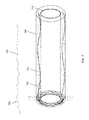
- FIG. 7 shows an exemplary and non-limiting schematic depiction of a corrosion-resistant fluid membrane system in accordance with aspects of the disclosure
- FIG. 8 shows an exemplary and non-limiting schematic depiction of a corrosion-resistant fluid membrane system in accordance with aspects of the disclosure
- FIG. 9 shows an exemplary and non-limiting schematic depiction of a corrosion-resistant fluid membrane system in accordance with aspects of the disclosure.
- FIGS. 10A-10C schematically depict aspects of exemplary and non-limiting pump assemblies of a corrosion-resistant fluid membrane system 700 in accordance with aspects of the disclosure
- FIG. 11 shows further aspects of an exemplary and non-limiting corrosion-resistant fluid membrane system in accordance with aspects of the disclosure
- FIG. 12 shows an exemplary and non-limiting depiction of a transportation system having an exemplary and non-limiting corrosion-resistant fluid membrane system in accordance with aspects of the disclosure
- FIGS. 13A and 13B show exemplary and non-limiting composite tube structures in accordance with aspects of the disclosure
- FIGS. 14A-14C schematically depict aspects of exemplary corrosion-resistance systems in accordance with aspects of the disclosure
- FIG. 15 shows an exemplary and non-limiting system environment in accordance with aspects of the disclosure.
- FIGS. 16 and 17 show exemplary and non-limiting flow diagrams for performing aspects of the present disclosure.
- the terms “about” and “approximately” indicate that the amount or value in question may be the specific value designated or some other value in its neighborhood. Generally, the terms “about” and “approximately” denoting a certain value is intended to denote a range within ⁇ 5% of the value. As one example, the phrase “about 100” denotes a range of 100 ⁇ 5, i.e. the range from 95 to 105. Generally, when the terms “about” and “approximately” are used, it can be expected that similar results or effects according to the disclosure can be obtained within a range of ⁇ 5% of the indicated value.
- the term “and/or” indicates that either all or only one of the elements of said group may be present.
- a and/or B indicates “only A, or only B, or both A and B.”
- only A the term also covers the possibility that B is absent, i.e. “only A, but not B.”
- substantially parallel refers to deviating less than 20° from parallel alignment and the term “substantially perpendicular” refers to deviating less than 20° from perpendicular alignment.
- parallel refers to deviating less than 5° from mathematically exact parallel alignment.
- perpendicular refers to deviating less than 5° from mathematically exact perpendicular alignment.
- composition comprising a compound A may include other compounds besides A.
- composition comprising a compound A may also (essentially) consist of the compound A.
- Embodiments of the present disclosure may be used in a transportation system, for example, as described in commonly-assigned application Ser. No. 15/007,783, titled “Transportation System,” the contents of which are hereby expressly incorporated by reference herein in their entirety.
- a high speed, high efficiency transportation system utilizes a low pressure environment in order to reduce drag on a vehicle at high operating speeds, thus providing the dual benefit of allowing greater speed potential and lowering the energy costs associated with overcoming drag forces.
- These systems may use a near vacuum within a tubular structure.
- These systems utilize any number of acceleration systems to achieve the high speed allowed, including, for example, electromagnetic levitation.
- the transportation system includes a capsule or transport pod 10 that is movable within a tube 20 having an interior maintained as a near-vacuum environment.
- a capsule 10 is traveling through the tube 20 , which may be supported above a ground surface (e.g., in an underwater environment) by a series of supports (e.g., pillars 22 ) spaced apart along a path of travel.
- a series of supports e.g., pillars 22
- the graph of FIG. 3 shows the effect of oxygen concentration on corrosion of mild steel in slowly moving distilled water. For example, as shown in the graph of FIG. 3 , below approximately 10 mL/liter, with decreasing concentrations of dissolved oxygen, corrosion rates decrease. The amount of oxygen present in an environment (and its ability to absorb electrons) dictates the rate of oxidation (corrosion) of metal. In accordance with aspects of the disclosure, by reducing the oxygen concentration of the fluid in contact with the outer surface of the metal tube (which may be susceptible to corrosion), the rate of corrosion of the metal tube may be reduced, and the degradative effects of corrosion can be reduced.
- an underwater tube e.g., an SFT
- the graph of FIG. 4 shows the effect of temperature on corrosion of iron in water containing dissolved oxygen. As shown in FIG. 4 , corrosion rates can increase with increased temperature. Additionally, colder-temperature water may contain less dissolved oxygen.
- a relatively colder environment e.g., deeper in a body of water
- salt concentrations also impact the rate of corrosion.
- typical corrosion rate of steel in seawater 25 gmd (or 0.005 ipy or 0.3 mm/yr).
- seawater in the world's oceans has a salinity of about 3.5% (35 g/L, or 0.600 M). Every kilogram (roughly one liter by volume) of seawater has approximately 35 grams (1.2 oz) of dissolved salts (predominantly sodium (Na+) and chloride (Cl ⁇ ) ions).
- Seawater pH is typically limited to a range between 7.5 and 8.4.
- the graph of FIG. 5 shows an effect of sodium chloride concentration on corrosion of iron in aerated solutions at room temperature.
- a sodium chloride concentration (by wt %) of 0 and 3 corrosion rate can increase with increased sodium chloride concentration. Above a sodium chloride concentration of 3%, with increasing sodium chloride concentration, the corrosion rate begins to decline. As seawater has an average sodium chloride concentration (by wt %) of about 3.5%, it should be understood that the exemplary graph of FIG. 5 indicates a high relative corrosion rate.
- by reducing the salt e.g.
- sodium chloride) concentration of the fluid in contact with the outer surface of the metal tube (which may be susceptible to corrosion), the rate of corrosion on the metal tube may be reduced, and the degradative effects of corrosion can be reduced.
- increasing the salt concentration of the fluid in contact with the outer surface of the metal tube may reduce the rate of corrosion on a tube and/or may increase the rate of growth of protective layers over the tube (for example, as discussed below), such that the degradative effects of corrosion are reduced.
- the graph of FIG. 6 shows an effect of pH level on corrosion of iron in aerated soft water at room temperature.
- iron corrodes slower in a neutral or basic fluid.
- the corrosion rate remains relatively constant (or flat).
- the corrosion rate begins to increase at an exponential rate.
- the corrosion rate decreases above a pH value of approximately 10.
- pH of seawater is typically limited to a range between about 7.5 and 8.4, it should be understood that the exemplary graph of FIG. 6 indicates a corrosion rate within the relatively flat region.
- a fluid may be treated to increase the basicity of the fluid in contact with the outer surface of the tube.
- the pH value may be increased, for example, to a relatively higher pH value, to a pH greater than 8.4, or to a pH greater than 10).
- the rate of corrosion of the tube may be reduced, and the degradative effects of corrosion can be reduced.
- the present disclosure is related to a structure, for example, a case or outer shell (e.g., a fluid-impermeable membrane) that is resistant to corrosion.
- the structure may be a case and may comprise a flexible, corrosion-resistant material.
- the case may be configured to substantially encapsulate the metallic surface of an object such that a cavity or channel is formed in between the case and the metallic surface of the object.
- the structure is arranged to surround walls of a metal tube such that one or more channels are provided between the tube and the structure.
- a hypoxic zone e.g., a small hypoxic zone
- the structure prevents (or reduces) contact between the outer surfaces of the tube and the seawater (having, for example, average ambient salt concentration, average ambient oxygen concentration, and/or ambient pH).
- a fluid having reduced sodium chloride concentration, reduced oxygen concentration, and/or increased pH value is passed through (e.g., passively, and/or using, e.g., pumps) the one or more channels such that the fluid having reduced sodium chloride concentration, reduced oxygen concentration, and/or increased pH value is in contact with the outer surfaces of the metal tube.
- the extent of corrosion for example, attributable to increased salt concentration levels, increased oxygen concentrations, and/or lower pH values, can be reduced and the degradative effects of corrosion on the metal tube can be reduced.
- the extent of corrosion for example, attributable to decreased salt concentration levels, decreased oxygen concentrations, and/or higher pH values, can be reduced and the degradative effects of corrosion on the tube can be reduced.
- a deoxidizer may be used to reduce oxygen concentration of treated water
- a reverse osmosis desalinization system may be used to reduce salt content of treated water.
- a pH adjuster may be used to adjust (e.g., raise) a pH value of water.
- a retentiate output of a reverse osmosis desalinization system may be used to increase salt content of treated water.
- FIG. 7 shows an exemplary and non-limiting schematic depiction of a corrosion-resistant fluid membrane system 700 in accordance with aspects of the disclosure.
- the corrosion-resistant fluid membrane system 700 includes a corrosion-resistant fluid membrane 705 .
- the fluid membrane 705 is impermeable (or substantially impermeable) to water.
- the corrosion-resistant fluid membrane system 700 may be employed upon (and/or around) a hollow tubular structure 710 .
- the corrosion-resistant fluid membrane may substantially surround, for example, a metallic hollow tubular structure 710 .
- FIG. 7 illustrates a section of tube (e.g., tubular structure 710 ), it should be understood that a transportation system may utilize one or more corrosion-resistant fluid membrane systems 700 arranged serially along the path of the transportation tube.
- these serially-arranged corrosion-resistant fluid membrane systems 700 may be discrete or may share and/or jointly utilize shared components.
- the metallic hollow tubular structure 710 may be submerged (e.g., partially or completely) under a surface of water 725 (e.g., seawater or freshwater), thereby potentially exposing the metallic hollow tubular structure 710 (if unprotected) to corrosion.
- a surface of water 725 e.g., seawater or freshwater
- the exemplary and non-limiting corrosion-resistant fluid membrane 705 is structured and arranged to prevent contact between the metallic hollow tubular structure 710 and the seawater.
- the exemplary and non-limiting corrosion-resistant fluid membrane 705 is structured and arranged to provide a channel 715 for flow of a fluid 720 in a direction (e.g., a single direction or multiple directions) around the metallic hollow tubular structure 710 between an inner surface of the membrane 705 and an outer surface of the tubular structure 710 .
- the fluid 720 is flowed through the channel 715 to provide corrosion resistance to the tubular structure 710 .
- FIG. 8 shows an exemplary and non-limiting schematic sectional view depiction of a corrosion-resistant fluid membrane system 700 in accordance with aspects of the disclosure.
- the corrosion-resistant fluid membrane system 700 includes a corrosion-resistant fluid membrane 705 .
- the corrosion-resistant fluid membrane system 700 may be employed upon (and/or around) a hollow tubular structure 710 .
- the corrosion-resistant fluid membrane may substantially surround, for example, a metallic hollow tubular structure 710 .
- the schematic depiction of FIG. 8 is not to scale, and the respective thicknesses of the hollow tubular structure 710 and the corrosion-resistant fluid membrane 705 , for example, may have significantly different thicknesses (e.g., differences in order(s) of magnitude).
- the hollow tubular structure 710 is configured as a transportation tube, in which a vehicle (e.g., a pod or capsule) 850 is operable to move along through the transportation tube using a propulsion system 855 (e.g., linear synchronous motor).
- a propulsion system 855 e.g., linear synchronous motor
- the interior 860 of the hollow tubular structure 710 may be configured and maintained as a low-pressure environment.
- the corrosion-resistant fluid membrane 705 may comprise a membrane or case (or cover) 705 and one or more pump assemblies 820 arranged, for example adjacent and/or on the membrane or case 705 .
- the one or more pump assemblies 820 may be placed at fixed distances along the circumference and/or length of the metallic surface of the object.
- the pump assemblies 820 may include one or more pumps (not shown), and are configured to draw in seawater 815 through one or more inlets 825 into one or more fluid (e.g., seawater) treatment systems (not shown).
- the fluid treatment systems may include, for example, one or more reverse osmosis modules operable to desalinate the seawater (or reduce the salt content of the fluid to some extent).
- the fluid treatment systems may utilize one or more reverse osmosis modules to increase the salt content of the fluid to some extent (e.g., for example when creating an environment conducive to growing a protective layer).
- the one or more water treatment systems may alternatively or further include one or more deoxygenating systems operable to remove oxygen from the fluid (e.g., seawater), so as to reduce the oxygen content of the fluid.
- the one or more water treatment systems may alternatively or further include one or more pH adjustment systems operable to adjust (e.g., raise) the pH of the incoming seawater, so as to increase the basicity of the incoming fluid (e.g., seawater or fresh water).
- the water treatment systems may comprise one or more water treatment modules, wherein the one or more modules may comprise one or more reverse osmosis modules, one or more deoxygenating modules, and one or more pH adjusting modules. In embodiments, these may include separate water treatment systems, and in other embodiments, these may include combined fluid treatment systems.
- the one or more pumps may then transport the treated seawater 830 (e.g., desalinated, deoxygenated, and/or pH-adjusted seawater) through a pump assembly outlet 835 and into the channel 715 formed between the case 705 and the metallic surface of the object (e.g., the hollow tubular structure 710 ).
- the treated seawater 830 may enter the channel 715 through a unidirectional valve 840 located on each of the one or more outlets 835 .
- the outlets 835 may include direction-controllable outlets (e.g., directional vanes, servo-controlled output tubes), operable to impart and/or adjust an output direction of the fluid flow of the treated seawater 830 .
- the one or more pump assemblies 820 may be configured to activate simultaneously, thereby allowing the treated fluid (e.g., desalinated and/or deoxygenated seawater) to flow through the channel in substantially the same direction (e.g., from one longitudinal end of the tube structure to the opposite longitudinal end of the tube structure).
- the one or more pump assemblies 820 may be configured to activate non-simultaneously (e.g., in a repeating synchronicity), thereby imparting a variable and/or circumferentially directed flow through the channel (e.g., from one longitudinal end of the tube structure to the opposite longitudinal end of the tube structure). While the exemplary depicted embodiment includes pump assemblies at one end of the tube, other contemplated embodiments may have pump assemblies at both longitudinal ends of the tube, for example, providing counter directed flows through, for example, adjacent channels.
- FIG. 9 shows an exemplary and non-limiting schematic depiction of a corrosion-resistant fluid membrane system 700 in accordance with aspects of the disclosure.
- the corrosion-resistant fluid membrane system 700 may comprise a case (or membrane) 705 and one or more pump assemblies 820 .
- the one or more pump assemblies 820 may be placed at fixed distances along the circumference and/or length of the metallic surface of the object.
- the pump assemblies 820 may include one or more pumps (not shown), and are configured to draw in seawater 815 through one or more inlets (not shown) into one or more water treatment systems (not shown).
- the one or more pumps may then transport the treated seawater 830 (e.g., desalinated, deoxygenated, and/or pH-adjusted seawater) through a pump assembly outlet 835 and into the channel 715 formed between the case 705 and the metallic surface of the object (e.g., the hollow tubular structure 710 ).
- the treated seawater 830 e.g., desalinated, deoxygenated, and/or pH-adjusted seawater
- the case 705 may further comprise one or more outlets 905 , wherein each of the one or more outlets 905 may be fitted with a unidirectional valve 910 .
- the unidirectional valve 910 prevents any flow backflow from the ambient environment into the channel 715 .
- the case 705 may further comprise one or more baffles 915 (e.g., one-way valve or seal) arranged within the channel 715 and configured to automatically and/or selectively open (e.g., passively and/or actively) and close the channel 715 or portions thereof (e.g., with an upstream fluid pressure above or below a threshold), to prevent or reduce any backwards flow of the treated fluid 830 (e.g., desalinated and/or deoxygenated seawater) through the channel 715 .
- baffles 915 e.g., one-way valve or seal
- FIG. 10A schematically depicts aspects of an exemplary and non-limiting pump assembly 820 of a corrosion-resistant fluid membrane system 700 in accordance with aspects of the disclosure.
- the exemplary pump assembly 820 may include one or more pumps 1005 .
- the one or more pumps 1005 in the one or more pump assemblies 820 may comprise any combination of the following types of pumps: a reverse osmosis pump; a turbine pump; a piston pump; an electromagnetic pump; a piezoelectric pump; a water driven mechanical pump; a high-pressure pump, a multistage centrifugal pump; and/or a heat pump.
- the one or more pumps 1005 are configured to draw in seawater 815 through one or more inlets 825 into one or more fluid treatment systems or fluid treaters 1010 .
- the fluid treaters 1010 may comprise one or more reverse osmosis modules operable to desalinate the seawater (or reduce the salt content to some extent).
- the low-pressure environment vacuum system i.e., used to provide the low-pressure environment with the transportation tube
- TMP trans-membrane pressure
- the one or more fluid treatment systems 1010 may alternatively or further include one or more deoxygenating systems operable to remove oxygen from the seawater, so as to reduce the oxygen content of the seawater.
- the one or more fluid treatment systems 1010 may alternatively or further include one or more pH adjustment systems operable to raise the pH of the incoming seawater, so as to increase the basicity of the incoming seawater (or fresh water).
- the one or more pumps 1005 may then transport the treated seawater 830 (e.g., desalinated, deoxygenated, and/or pH-adjusted seawater) through a pump assembly outlet 835 and into the channel 715 formed between the case 705 and the metallic surface 1020 of the object (e.g., the hollow tubular structure 710 ).
- the treated seawater 830 e.g., desalinated and/or deoxygenated seawater
- the outlets 835 may include direction-controllable outlets (e.g., servo-controlled individual flaps 1025 of the unidirectional valve 840 ) operable to impart and/or adjust an output direction of the fluid flow of the treated seawater 830 .
- direction-controllable outlets e.g., servo-controlled individual flaps 1025 of the unidirectional valve 840
- the pump assembly may also include one or more of check valves, flow meters, regulators, and other conventional components of a fluid processing and delivery system.
- FIG. 10B schematically depicts aspects of a further exemplary and non-limiting pump assembly 820 ′ of a corrosion-resistant fluid membrane system 700 in accordance with aspects of the disclosure.
- at least one of the one or more pump assemblies 820 ′ may comprise a heat pump 1055 , for example, as shown in FIG. 10B .
- the pump assembly 820 ′ further comprises a heat exchanger 1060 .
- the one or more heat pumps 1055 are configured to draw in seawater 815 through one or more inlets 825 into one or more fluid treatment systems or fluid treaters 1010 , and then transport the treated seawater 830 (e.g., desalinated, deoxygenated, and/or pH-adjusted seawater) through a pump assembly outlet 835 and into the channel 715 formed between the case 705 and the metallic surface 1020 of the object (e.g., the hollow tubular structure 710 ).
- the treated seawater 830 e.g., desalinated, deoxygenated, and/or pH-adjusted seawater
- the heat pump 1055 may be configured to capture thermal energy 1070 , which the heat exchanger 1060 then delivers to the treated fluid 830 (or yet to be treated fluid 815 , depending on the order of the elements of the pump assembly 820 ′).
- the treated fluid 830 upon exiting the pump assembly output 835 , includes added thermal energy from the heat pump 1055 via the heat exchanger 1060 .
- the treated fluid 830 with added thermal energy may be output from the pump assembly 820 ′ and input (or injected) into a particular region of the channel 715 (e.g., a lower portion) to thereby create a convection cell within the channel (see, e.g., FIG. 11 ).
- the treated fluid 830 with added thermal energy may be output from the pump assembly 820 ′ and input (or injected) into the channel 715 to provide an environment having properties that are more conducive to and/or promote the growth of protective layers (for example, as discussed below).
- the pump assembly 820 may additionally comprise one or more fluid testers 1008 .
- the one or more fluid testers 1008 are operable to assess and/or quantify one or more properties of the incoming fluid (e.g., ambient seawater), including, for example, salt concentration, pH value, oxygen concentration of the incoming seawater.
- the one or more fluid treaters 1010 may, for example, more efficiently and/or more effectively treat the incoming fluid, as necessary, and, for example, in real-time, to achieve a treated fluid having certain desired properties (e.g., of salt concentration, oxygen concentration, and/or pH value) for reducing corrosion of the metal tube.
- certain desired properties e.g., of salt concentration, oxygen concentration, and/or pH value
- FIG. 10C schematically depicts aspects of a further exemplary and non-limiting pump assembly 820 ′′ of a corrosion-resistant fluid membrane system 700 in accordance with aspects of the disclosure.
- the pump assembly 820 ′′ comprises a heat pump 1055 and heat exchanger 1060 .
- the one or more heat pumps 1055 are configured to draw in seawater 815 through one or more inlets 825 into one or more fluid treatment systems or fluid treaters 1010 , and then transport the treated seawater 830 (e.g., desalinated, deoxygenated, and/or pH-adjusted seawater) through a pump assembly outlet 835 and into the channel 715 formed between the case 705 and the metallic surface 1020 of the object (e.g., the hollow tubular structure 710 ).
- the treated seawater 830 e.g., desalinated, deoxygenated, and/or pH-adjusted seawater
- the pump assembly 820 ′′ further comprises one or more turbines 1075 .
- the heat exchanger 1055 then delivers the captured thermal energy 1070 to the one or more turbines 1075 to drive the turbines 1075 .
- the one or more turbines 1075 are operable to drive the treated fluid 830 (e.g., desalinated and/or deoxygenated seawater) forward through the channel 715 of the system 700 .
- FIG. 11 schematically illustrates a treated fluid 830 with added thermal energy that is injected into a particular region of the channel 715 (e.g., a lower portion) to thereby create a convection cell within the channel 715 , in accordance with aspects of the disclosure.
- a heat pump 1055 may be configured to capture thermal energy, which a heat exchanger then delivers to the treated fluid 830 .
- the treated fluid 830 upon exiting the pump assembly output, the treated fluid 830 includes added thermal energy from the heat pump via the heat exchanger.
- utilizing the convective flow may provide for or supplement a circulation rate of fluid through the channel 715 , and/or may induce or enhance mixing and/or homogeneity of the treated fluid.
- a corrosion inhibiting solution may be introduced to the treated fluid 830 (e.g., the desalinated and/or deoxygenated seawater).
- the corrosion inhibiting solution may combat the corrosive properties of salt, oxygen, or anaerobic bacteria still present in the treated fluid 830 (e.g., desalinated and/or deoxygenated seawater).
- Corrosion inhibitors are additives to the fluids that surround the metal or related object.
- a corrosion inhibitor is a chemical compound that, when added to a liquid or gas, decreases the corrosion rate of a material, typically a metal or an alloy. The effectiveness of a corrosion inhibitor may depend on fluid composition, quantity of water, and/or flow regime.
- a common mechanism for inhibiting corrosion involves formation of a coating, often a passivation layer, which prevents access of the corrosive substance to the metal.
- the corrosion inhibiting solution may include chemicals that form an electrically insulating or chemically impermeable coating on exposed metal surfaces, to suppress electrochemical reactions. Such methods make the system less sensitive to scratches or defects in the coating, since extra inhibitors can be made available wherever metal becomes exposed.
- Chemicals that inhibit corrosion may include, for example, chromates, phosphates, polyaniline, other conducting polymers and/or a wide range of specially-designed chemicals that resemble surfactants (e.g., long-chain organic molecules with ionic end groups).
- a corrosion inhibiting solution may include bacteria, and may provide for applying one or more bacterial films to the surface of metals in corrosive environments, which may increase the corrosion resistance of the metal tube substantially.
- antimicrobial-producing biofilms can be used to inhibit mild steel corrosion from, for example, sulfate-reducing bacteria.
- FIG. 12 shows an exemplary and non-limiting depiction of a transportation system having an exemplary and non-limiting corrosion-resistant fluid membrane system 700 in accordance with aspects of the disclosure.
- a capsule 10 is traveling through the tube 710 of a transportation system, which is supported in an underwater environment 1200 (e.g., in an undersea environment) by a series of supports (e.g., pillars 22 ) spaced apart along a path of travel. That is, in contrast to an SFT, for example discussed herein, the exemplary and non-limiting embodiment of FIG. 12 includes at least a portion of tube that may be, for example, more rigidly supported in an underwater environment 1200 by pillars 22 .
- the corrosion-resistant fluid membrane system 700 includes a corrosion-resistant fluid membrane 705 that is impermeable (or substantially impermeable) to fluids, e.g., seawater. As shown in FIG. 12 , in embodiments, the corrosion-resistant fluid membrane system 700 may be employed upon (and/or around) a hollow tubular structure 710 . As shown in FIG. 12 , the corrosion-resistant fluid membrane may substantially surround, for example, a metallic hollow tubular structure 710 .
- FIG. 12 illustrates a few sections of tube (e.g., tubular structure 710 ) utilizing one or more corrosion-resistant fluid membranes 705 arranged serially along the path of the transportation tube.
- these serially-arranged corrosion-resistant fluid membranes 705 of the corrosion-resistant fluid membrane system 700 may be discrete or may share and/or jointly utilize shared components.
- the metallic hollow tubular structure 710 may be submerged (e.g., partially or completely) in an underwater environment 1200 (e.g., seawater or freshwater), thereby potentially exposing the metallic hollow tubular structure 710 (if unprotected) to corrosion.
- an underwater environment 1200 e.g., seawater or freshwater
- the exemplary and non-limiting corrosion-resistant fluid membrane 705 prevents contact between the metallic hollow tubular structure 710 and the seawater and provides a channel 715 for flow of a fluid 830 in a direction around the metallic hollow tubular structure 710 between an inner surface of the membrane 705 and an outer surface of the tubular structure 710 .
- the treated fluid 830 is flowed through the channel 715 to provide corrosion resistance to the tubular structure 710 .
- the flow of the fluid 830 is in a direction opposite to the travel direction of the capsule in the transportation tube.
- the flow of the fluid 830 may be in a same direction as the travel direction of the capsule in the transportation tube.
- the corrosion-resistant fluid membrane 705 is illustrated as transparent to more clearly depict aspects of the disclosure.
- the corrosion-resistant fluid membrane 705 may be transparent, translucent, or opaque.
- a transparent membrane 705 may allow visible detection of any effects of corrosion on the tubular structure 710 .
- the membranes 705 may connect between or adjacent respective tube support structures (e.g., structural reinforcement rings 1210 ) using one or more attachment structures 1215 .
- the one or more attachment structures 1215 may include, for example, tension clamps, rivets, and/or adhesives, amongst other contemplated attachment structures.
- the corrosion-resistant fluid membrane system 700 may include, for example, a smaller corrosion-resistant fluid membrane 705 ′ having a different configuration attached between the adjacent reinforcement rings 1210 .
- the region between adjacent reinforcement rings 1210 at the pillar(s) 22 may remain uncovered by a corrosion-resistant fluid membrane.
- the pump assemblies 820 may be arranged on or adjacent an exterior region of the corrosion-resistant fluid membrane 705 .
- pump assemblies 1220 may be arranged on or adjacent reinforcement rings 1210 (e.g., in communication with the channels 715 via passageways provided through the reinforcement rings 1210 ).
- the pump assemblies 1220 may be on or adjacent reinforcement rings 1210 in the region between adjacent reinforcement rings 1210 at the pillar(s) 22 (which region, for example, in embodiments, may remain in communication with ambient seawater).
- embodiments of the present disclosure have been shown with tubular shapes, the disclosure contemplates the case or membrane in other configurations.
- embodiments of the present disclosure may utilize structures described in commonly-assigned application Ser. No. 15/008,017, titled “Low-Pressure Environment Structures,” the contents of which are hereby expressly incorporated by reference herein in their entirety.
- FIGS. 13A and 13B show exemplary and non-limiting embodiments of a corrosion-resistant fluid membrane system 1300 having a composite tube structure in accordance with aspects of the disclosure.
- the corrosion-resistant fluid membrane system 1300 may comprise a case 1305 and one or more pump assemblies 1320 .
- the case (or membrane) 1305 may comprise, for example, an inexpensive, flexible, corrosion-resistant shell (e.g., a high-density polyethylene membrane).
- an inexpensive, flexible, corrosion-resistant shell e.g., a high-density polyethylene membrane
- the pump assembly 1320 includes a high-pressure pump 1330 , and is configured to draw in seawater through one or more inlets 1325 into one or more water treatment systems (for example, including a desalination reverse osmosis unit 1333 ).
- the high-pressure pump 1330 is operable to transport the treated seawater (e.g., desalinated seawater) through a pump assembly outlet 1335 and into the channel 1315 formed between the case 1305 and the metallic surface of the object (e.g., the hollow tubular structure 1310 ).
- a plurality of molded studs 1350 may be structured and arranged within the channel 1315 to maintain a gap between inner tube 1310 and corrosion-resistant shell 1305 .
- fins e.g., molded helical fins 1360
- the channel 1315 may be structured and arranged within the channel 1315 (e.g., depending from an interior surface of the shell 1305 ) to promote circumferential flow 1365 (or a circumferential component of flow) to the treated fluid.
- osmotic pressure is approximately 339 PSI or 23 ATM or 2.3 MPA.
- a pressure at the outlet 1340 (with a one-way valve) or outlet pressure OUTLET (P P ocean ).
- the corrosion-resistant fluid membrane system 1300 comprises a case (or membrane) 1305 and one or more pump assemblies 1320 .
- the pump assembly 1320 includes a high-pressure pump 1330 , and a water treatment system including a desalination reverse osmosis desalination unit 1333 .
- the high-pressure pump 1330 is operable to transport the treated seawater (e.g., desalinated seawater) through a pump assembly outlet 1335 and into the channel 1315 formed between the case 1305 and the metallic surface of the object (e.g., the hollow tubular structure 1310 ).
- support braces 1375 connected between the case 1305 and elements of the pump assembly 1320 may be utilized to support the pump assembly 1320 .
- molded studs 1370 (which, for example do not traverse the entire width of the channel 1315 ) may optionally be provided within the channel 1315 , for example, to induce mixing and/or homogeneity of the treated fluid.
- FIGS. 14A and 14B show an exemplary and non-limiting composite tube structure 1400 in accordance with aspects of the disclosure.
- the tube structure 1400 may include a metal tube 1410 and the outer shell 1405 (e.g., a corrosion resistant cover, or membrane, for example, HDPE), with an intermediate layer 1415 arranged between the metal tube 1410 and the outer shell 1405 .
- the outer shell 1405 may be optimized for the ambient environmental conditions (e.g., to reduce wear from weather and/or corrosion). Additionally, for example, in embodiments, the outer shell 1405 may be optimized to be resistant to puncture from, for example, gun shots.
- the “channel” or void may be “filled” such that the intermediate layer 1415 is in contact with and surrounds the metal tube 1410 .
- the intermediate layer 1415 may comprise a layer formed by calcium accretion, or “biorock,” which may fill the void (e.g., completely or partially) between the outer shell 1405 and metallic surface 1410 .
- Accretions refer to the substance formed by electro-accumulation of minerals dissolved in seawater. The biorock building process grows cement-like structures, often in salt water. Accretion works by passing a small electric current through electrodes in the water. The accretion structure grows more or less without limit as long as current flows.
- a low voltage electric current which is completely safe, for example, for swimmers and marine life
- a submerged conductive structure e.g., the metal transportation tube 1410
- dissolved minerals in seawater e.g., calcium, magnesium and/or bicarbonate
- the result is a composite 1415 , e.g., of brucite hydromagnesite and limestone, with mechanical strength similar to concrete formed on the exterior of the transportation tube structure (or, in embodiments, between the transportation tube structure 1410 and the outer shell 1405 ).
- the accretion material is derived from seawater, this material is similar to the composition of natural coral reefs and tropical sand beaches.
- calcium carbonate aragonite
- cathodic protection replaces the negative chloride (Cl ⁇ ) ion with dissolved bicarbonate (HCO 3 ⁇ ) to harden the coating to a hydromagnesite-aragonite mixture with gaseous hydrogen being evolved through the porous structure.
- the accretion coatings can thicken at the rate of 5 cm per year. As long as current flows, the structure continues to get larger and stronger. An accretion structure can also “heal” itself if damaged, making it particularly useful as a replacement for concrete in hard-to-access locations.
- Accretion structures can be built in any size or shape depending only on the physical makeup of the sea bottom, wave, current energies and/or construction materials. Accretion structures may be well suited for remote, third world sites, for example, where exotic building materials, construction equipment and highly skilled labor may be in short supply or non-existent.
- Accretion structures may range in compressive strength from, for example, 3720 to 5350 lbf/in 2 (26 to 37 MPa)—for comparison, the concrete typically used in sidewalks has a lower strength of about 3500 lbf/in 2 (24 MPa).
- one of the main components of accretion structures is magnesium hydroxide, and another main component is calcium carbonate, which is chiefly the result of the ionic composition of seawater.
- one kilowatt hour of electricity will result in the accretion of about 0.4 to 1.5 kg (0.9 to 3.3 lb) of biorock, depending on various parameters such as depth, electric current, salinity, and/or water temperature.
- biorock Using accretion structures (or “biorock”) is cost-effective, and the process utilizes metal bars or similar conductive structures to conduct electricity along the base (or foundation) structure (e.g., metal tube) and a small amount of electricity.
- biorock formation may utilize electricity provided from fossil fuels (which generates CO 2 ), but may also utilize solar power, wind power, tidal power, and/or wave power (which power sources do not produce CO 2 ).
- the resulting accretion material may be cheaper than concrete blocks in many places, depending, for example, on local electricity and/or cement transport costs.
- the void between the metal tube 1410 and the outer shell 1405 with a resin (e.g., a static epoxy resin).
- a resin e.g., a static epoxy resin
- growth acceleration of the calcium accretion layer e.g., carbonate (aragonite) protective layer
- enhancement of structural properties the accretion layer may be tailored by controlling the environment around the tube or within the channel prior to accretion formation.
- an outer shell may be used to provide a channel along the exterior of the metal tube, and an enhanced accretion layer is formed within the channel by controlling the environment (e.g. controlling one or more properties of the treated fluid) around the tube or within the channel prior to accretion formation and/or during accretion formation.
- the outer shell may be utilized as a “temporary” covering that provides an environment conducive to accretion formation, e.g., while the accretion layer is being formed, but that may later be removed (or destroyed, e.g., by accretion formation) after a sufficient accretion layer has been formed around the tube.
- a mild electric current may be used to precipitate, e.g., calcium carbonate on a metal exterior of the structure, thus, once formed, intervening between the metal exterior of the tube and the seawater, thus preventing contact between the metal exterior and the sea water.
- the formed accretion layer is operable to provide a layer of corrosion protection to the metal exterior of the structure.
- FIG. 14C shows an exemplary and non-limiting composite tube structure 1400 ′ in accordance with further aspects of the disclosure.
- the tube structure 1400 ′ may include a metal tube 1410 an outer layer 1415 ′ arranged on the metal tube 1410 (for example, without a corresponding membrane or outer shell).
- the outer layer 1415 ′ may comprise a layer formed by calcium accretion, or “biorock”, which may cover (e.g., completely or partially) the metallic surface of the metal tube 1410 so as to provide corrosion-resistance to the metal tube 1410 .
- the system may utilize petrolatum-based tapes, e.g., a synthetic fiber-reinforced tape impregnated and coated with a specially formulated, petrolatum based compound containing inert fillers and water displacing agents.
- the tape provides a long-lasting anti-corrosion layer for steel and concrete surfaces, by displacing water, sealing out oxygen and forming a moisture resistance bond, for example, in a region not covered with an outer shell 1405 and/or to connect adjacent regions of outer shell 1405 to one another and/or to other structures.
- a tough outer cover e.g., a HDPE, UV resistant material
- the outer cover may provide mechanical protection, for example, against the elements and/or accidental impact.
- Embodiments of the present disclosure may also use, for example, stainless steel fasteners, e.g., 316 SS marine grade stainless steel bolts, nuts and washers, for example, to secure components of the corrosion-resistant fluid membrane system to one another and/or to the tubular structure.
- stainless steel fasteners e.g., 316 SS marine grade stainless steel bolts, nuts and washers
- Other materials that may be used for the corrosion-resistant fluid membrane system include petrolatum tapes and coatings, polyurethanes, HDPE, Polyesters, Fiberglass, Polypropylenes, and PVC, amongst other contemplated materials.
- control systems for one or more corrosion resistant fluid membrane systems 700 can be implemented by such special purpose hardware-based systems that perform the specified functions or acts, or combinations of special purpose hardware and computer instructions and/or software, as described above.
- the control systems may be implemented and executed from either a server, in a client server relationship, or they may run on a user workstation with operative information conveyed to the user workstation.
- the software elements include firmware, resident software, microcode, etc.
- aspects of the present disclosure may be embodied as a system, a method or a computer program product. Accordingly, aspects of embodiments of the present invention may take the form of an entirely hardware embodiment, an entirely software embodiment (including firmware, resident software, micro-code, etc.) or an embodiment combining software and hardware aspects that may all generally be referred to herein as a “circuit,” “module” or “system.” Furthermore, aspects of the present disclosure (e.g., control systems) may take the form of a computer program product embodied in any tangible medium of expression having computer-usable program code embodied in the medium.
- the computer-usable or computer-readable medium may be, for example but not limited to, an electronic, magnetic, optical, electromagnetic, infrared, or semiconductor system, apparatus, device, or propagation medium. More specific examples (a non-exhaustive list) of the computer-readable medium would include the following:
- a computer-usable or computer-readable medium may be any medium that can contain, store, communicate, propagate, or transport the program for use by or in connection with the instruction execution system, apparatus, or device.
- the computer-usable medium may include a propagated data signal with the computer-usable program code embodied therewith, either in baseband or as part of a carrier wave.
- the computer usable program code may be transmitted using any appropriate medium, including but not limited to wireless, wireline, optical fiber cable, RF, etc.
- Computer program code for carrying out operations of the present invention may be written in any combination of one or more programming languages, including an object oriented programming language such as Java, Smalltalk, C++ or the like and conventional procedural programming languages, such as the “C” programming language or similar programming languages.
- the program code may execute entirely on the user's computer, partly on the user's computer, as a stand-alone software package, partly on the user's computer and partly on a remote computer or entirely on the remote computer or server.
- the remote computer may be connected to the user's computer through any type of network. This may include, for example, a local area network (LAN) or a wide area network (WAN), or the connection may be made to an external computer (for example, through the Internet using an Internet Service Provider).
- the present invention may be embodied in a field programmable gate array (FPGA).
- FPGA field programmable gate array
- FIG. 15 shows an exemplary system environment and control for a corrosion resistant fluid membrane system in accordance with the embodiments described herein in accordance with aspects of the disclosure.
- the system 3900 is generally shown and may include a computer system 3902 , which is generally indicated.
- the computer system 3902 may operate as a standalone device or may be connected to other systems or peripheral devices (e.g., computer 3920 ).
- the computer system 3902 may include, or be included within, any one or more computers, servers, systems, communication networks or cloud environment. As shown in FIG.
- the system 3900 may be used to control one or more controllers 1015 and/or one or more controller communicators 1505 , wherein the one or more controllers 1015 may be operable to control one or more pumps 1005 and/or one or more fluid treaters 1010 of, for example, individual pumping assemblies.
- the controller communicator 1505 may directly communicate with one or more controllers 1015 (e.g., remotely located along a transportation path), via, for example, WiFi, Bluetooth.
- the controller communicator 1505 may directly communicate with one or more controllers 1015 via a network 3922 .
- the computer system 3902 may operate in the capacity of a server in a network environment, or in the capacity of a client user computer in the network environment.
- the computer system 3902 or portions thereof, may be implemented as, or incorporated into, various devices, such as a personal computer, a tablet computer, a set-top box, a personal digital assistant, a mobile device, a palmtop computer, a laptop computer, a desktop computer, a communications device, a wireless telephone, a personal trusted device, a web appliance, or any other machine capable of executing a set of instructions (sequential or otherwise) that specify actions to be taken by that device.
- additional embodiments may include any collection of systems or sub-systems that individually or jointly execute instructions or perform functions.
- the computer system 3902 may include at least one processor 3904 , such as, for example, a central processing unit, a graphics processing unit, or both.
- the computer system 3902 may also include a computer memory 3906 and a bus 3918 .
- the computer memory 3906 may include a static memory, a dynamic memory, or both.
- the computer memory 3906 may additionally or alternatively include a hard disk, random access memory, a cache, or any combination thereof.
- the computer memory 3906 may comprise any combination of known memories or a single storage.
- the computer system 3902 may include a computer display 3908 , such as a liquid crystal display, an organic light emitting diode, a flat panel display, a solid state display, a cathode ray tube, a plasma display, or any other known display.
- the computer system 3902 may include at least one computer input device 3910 , such as a keyboard, a remote control device having a wireless keypad, a microphone coupled to a speech recognition engine, a camera such as a video camera or still camera, a cursor control device, or any combination thereof.
- a computer input device 3910 such as a keyboard, a remote control device having a wireless keypad, a microphone coupled to a speech recognition engine, a camera such as a video camera or still camera, a cursor control device, or any combination thereof.
- a computer input device 3910 such as a keyboard, a remote control device having a wireless keypad, a microphone coupled to a speech recognition engine, a camera such as a video camera or still camera, a
- the computer system 3902 may also include a medium reader 3912 and a network interface 3914 . Furthermore, the computer system 3902 may include any additional devices, components, parts, peripherals, hardware, software or any combination thereof which are commonly known and understood as being included with or within a computer system, such as, but not limited to, an output device 3916 .
- the output device 3916 may be, but is not limited to, a speaker, an audio out, a video out, a remote control output, or any combination thereof.
- aspects of the disclosure may take the form of a computer program product accessible from a computer-usable or computer-readable medium providing program code for use by or in connection with a computer or any instruction execution system.
- the software and/or computer program product can be implemented in the environment of FIG. 15 .
- a computer-usable or computer readable medium can be any apparatus that can contain, store, communicate, propagate, or transport the program for use by or in connection with the instruction execution system, apparatus, or device.
- the medium can be an electronic, magnetic, optical, electromagnetic, infrared, or semiconductor system (or apparatus or device) or a propagation medium.
- Examples of a computer-readable storage medium include a semiconductor or solid state memory, magnetic tape, a removable computer diskette, a random access memory (RAM), a read-only memory (ROM), a rigid magnetic disk and an optical disk.
- Current examples of optical disks include compact disk-read only memory (CD-ROM), compact disc-read/write (CD-R/W) and DVD.
- FIGS. 16 and 17 show exemplary flows for performing aspects of the present disclosure.
- the steps of FIGS. 16 and 17 may be implemented in the environment of FIG. 15 , for example.
- the flow diagram may equally represent a high-level block diagram of embodiments of the disclosure.
- the flowchart and/or block diagrams of FIGS. 16 and 17 illustrate the architecture, functionality, and operation of possible implementations of systems, methods and computer program products according to various embodiments of the present disclosure.
- each block in the flowcharts or block diagrams may represent a module, segment, or portion of code, which comprises one or more executable instructions for implementing the specified logical function(s), (and/or it may represent a piece of hardware).
- each block of each flowchart, and combinations of the flowchart illustrations can be implemented by special purpose hardware-based systems that perform the specified functions or acts, or combinations of special purpose hardware and computer instructions and/or software, as described above.
- the steps of the flow diagram may be implemented and executed from either a server, in a client server relationship, or they may run on a user workstation with operative information conveyed to the user workstation.
- the software elements include firmware, resident software, microcode, etc.
- embodiments of the disclosure can take the form of a computer program product accessible from a computer-usable or computer-readable medium providing program code for use by or in connection with a computer or any instruction execution system.
- the software and/or computer program product can be implemented in the environment of FIG. 15 .
- a computer-usable or computer readable medium can be any apparatus that can contain, store, communicate, propagate, or transport the program for use by or in connection with the instruction execution system, apparatus, or device.
- the medium can be an electronic, magnetic, optical, electromagnetic, infrared, or semiconductor system (or apparatus or device) or a propagation medium.
- Examples of a computer-readable storage medium include a semiconductor or solid state memory, magnetic tape, a removable computer diskette, a random access memory (RAM), a read-only memory (ROM), a rigid magnetic disk and an optical disk.
- Current examples of optical disks include compact disk-read only memory (CD-ROM), compact disc-read/write (CD-R/W) and DVD.
- FIG. 16 illustrates an exemplary flow 1600 for proving corrosion protection to a structure.
- a fluid e.g., seawater
- a pump assembly e.g., via an inlet using a pump.
- properties of the fluid may be tested (e.g., determined and/or quantified) by one or more testing devices.
- Tested properties may include, for example, salt concentration, pH level, oxygen concentration, and the one or more testing devices may include a salt concentration measurer, pH level measurer, and/or an oxygen concentration measurer.
- the fluid is treated by one or more fluid treatment devices, resulting in a treated fluid.
- the fluid treatment devices may include one or more of a desalination apparatus, a deoxidizer apparatus, a pH adjustment device, and/or a fluid additive device.
- the treated fluid is injected into the channel between the exterior of the metal tube and the cover (or membrane), for example, at one end of the channel.
- the treated fluid is flowed through the channel along the exterior of the metal tube, so as to provide corrosion resistance to the exterior of the metal tube.
- the treated fluid is ejected from the channel, for example, through one or more channel outlets.
- FIG. 17 illustrates an exemplary flow 1700 for proving corrosion protection to a structure.
- the channel fluid may be pumped through the channel intermittently, for example, as necessary, determined by testing fluid currently in the channel.
- energy consumption and wear may be reduced while providing sufficient protection to the structure.
- flow conditions may be defined. Such conditions may include, for example, fluid temperature, fluid pH, fluid salt concentration, fluid flow rates, pressure gradients, and/or axial homogeneity.
- properties of the fluid e.g., fluid temperature, fluid pH, fluid salt concentration, fluid flow rates
- flow conditions may be tested and measured, for example, at the inlet and/or at the outlet of the channel using one or more sensors (e.g., thermometers, pH measurers, salt concentration measures, flow meters).
- sensors e.g., thermometers, pH measurers, salt concentration measures, flow meters.
- one or more of the measured properties and/or conditions are compared to the defined conditions. If, at step 1715 , the measured properties/conditions are sufficient, with this exemplary embodiment, at step 1720 , the inlet and/or outlet pumps may be deactivated, at step 1725 , convection cell pumps (e.g., internal channel pumps) may be activated, and at step 1730 , fluid treatment may be ceased.
- convection cell pumps e.g., internal channel pumps
- step 1710 a determination of nominal operation is performed, e.g., by a computer system monitoring operational parameters. If, at step 1745 , operation is determined to be nominal, the process continues at step 1710 . If, at step 1745 , operation is determined to not be nominal (e.g., a pump failure is detected and/or low additive layers are detected), at step 1750 , an alert may flagged (e.g., alarm, light, and/or sound).
- the present disclosure provides various systems, structures, methods, and apparatuses.
- the words that have been used are words of description and illustration, rather than words of limitation. Changes may be made within the purview of the appended claims, as presently stated and as amended, without departing from the scope and spirit of the disclosure in its aspects.
- the disclosure has been described with reference to particular materials and embodiments, embodiments of the invention are not intended to be limited to the particulars disclosed; rather the invention extends to all functionally equivalent structures, methods, and uses such as are within the scope of the appended claims.
- While the computer-readable medium may be described as a single medium, the term “computer-readable medium” includes a single medium or multiple media, such as a centralized or distributed database, and/or associated caches and servers that store one or more sets of instructions.
- the term “computer-readable medium” shall also include any medium that is capable of storing, encoding or carrying a set of instructions for execution by a processor or that cause a computer system to perform any one or more of the embodiments disclosed herein.
- the computer-readable medium may comprise a non-transitory computer-readable medium or media and/or comprise a transitory computer-readable medium or media.
- the computer-readable medium can include a solid-state memory such as a memory card or other package that houses one or more non-volatile read-only memories.
- the computer-readable medium can be a random access memory or other volatile re-writable memory.
- the computer-readable medium can include a magneto-optical or optical medium, such as a disk, tapes or other storage device to capture carrier wave signals such as a signal communicated over a transmission medium. Accordingly, the disclosure is considered to include any computer-readable medium or other equivalents and successor media, in which data or instructions may be stored.
- inventions of the disclosure may be referred to herein, individually and/or collectively, by the term “invention” merely for convenience and without intending to voluntarily limit the scope of this application to any particular invention or inventive concept.
- inventions merely for convenience and without intending to voluntarily limit the scope of this application to any particular invention or inventive concept.
- specific embodiments have been illustrated and described herein, it should be appreciated that any subsequent arrangement designed to achieve the same or similar purpose may be substituted for the specific embodiments shown.
- This disclosure is intended to cover any and all subsequent adaptations or variations of various embodiments. Combinations of the above embodiments, and other embodiments not specifically described herein, will be apparent to those of skill in the art upon reviewing the description.
Abstract
Description
-
- an electrical connection having one or more wires,
- a portable computer diskette,
- a hard disk,
- a random access memory (RAM),
- a read-only memory (ROM),
- an erasable programmable read-only memory (EPROM or Flash memory),
- an optical fiber,
- a portable compact disc read-only memory (CDROM),
- an optical storage device,
- a transmission media such as those supporting the Internet or an intranet,
- a magnetic storage device,
- a usb key, and/or
- a mobile phone.
Claims (18)
Priority Applications (1)
| Application Number | Priority Date | Filing Date | Title |
|---|---|---|---|
| US15/434,622 US10077540B2 (en) | 2016-02-16 | 2017-02-16 | Corrosion-resistant fluid membrane |
Applications Claiming Priority (2)
| Application Number | Priority Date | Filing Date | Title |
|---|---|---|---|
| US201662295828P | 2016-02-16 | 2016-02-16 | |
| US15/434,622 US10077540B2 (en) | 2016-02-16 | 2017-02-16 | Corrosion-resistant fluid membrane |
Publications (2)
| Publication Number | Publication Date |
|---|---|
| US20170233977A1 US20170233977A1 (en) | 2017-08-17 |
| US10077540B2 true US10077540B2 (en) | 2018-09-18 |
Family
ID=59561272
Family Applications (1)
| Application Number | Title | Priority Date | Filing Date |
|---|---|---|---|
| US15/434,622 Expired - Fee Related US10077540B2 (en) | 2016-02-16 | 2017-02-16 | Corrosion-resistant fluid membrane |
Country Status (2)
| Country | Link |
|---|---|
| US (1) | US10077540B2 (en) |
| WO (1) | WO2017143068A1 (en) |
Families Citing this family (2)
| Publication number | Priority date | Publication date | Assignee | Title |
|---|---|---|---|---|
| US11660572B2 (en) | 2017-09-22 | 2023-05-30 | Dehlsen Associates of the Pacific, Limited | Wind and wave desalination vessel |
| CN109610511B (en) * | 2018-12-14 | 2019-08-23 | 黄夏羿 | Suspension high-speed rail tunnel structure, construction and its control method in water over strait |
Citations (16)
| Publication number | Priority date | Publication date | Assignee | Title |
|---|---|---|---|---|
| US2200469A (en) | 1939-11-08 | 1940-05-14 | Cox George Chandler | Anticorrosive and antifouling coating and method of application |
| US4246075A (en) | 1979-03-19 | 1981-01-20 | Marine Resources Company | Mineral accretion of large surface structures, building components and elements |
| US5127441A (en) | 1985-12-16 | 1992-07-07 | Rains Robert L | Coaxial piping system |
| US5961837A (en) | 1992-03-30 | 1999-10-05 | Ferrara; Marcello | Process for treatment of industrial waste |
| US6105941A (en) | 1998-07-22 | 2000-08-22 | Exxon Research And Engineering Company | Vapor/liquid contacting cyclone with device to prevent backmixing and process for using the same |
| US6450734B1 (en) | 1997-05-09 | 2002-09-17 | Michael W. Kuja | Transportation underwater tunnel system |
| US20030116214A1 (en) * | 2001-12-26 | 2003-06-26 | Paul Meli | Secondary containment system for pipelines |
| US20060196568A1 (en) * | 2005-01-10 | 2006-09-07 | Leeser Daniel L | Flexible, compression resistant and highly insulating systems |
| US7186327B1 (en) | 1997-09-30 | 2007-03-06 | Russell Larry L | Method and apparatus for scaling control and in-situ cathodic protection |
| US20070215546A1 (en) | 2006-03-17 | 2007-09-20 | Scott Watkins | Method of integrating water treatment assemblies |
| WO2008041862A2 (en) | 2006-10-05 | 2008-04-10 | Hans-Olav Ottersen | Heat exchanger |
| US20080296890A1 (en) * | 2004-03-26 | 2008-12-04 | Fluor Technologies Corporation | Cryogenic Pipeline Configurations and Methods |
| WO2013002644A1 (en) | 2011-06-30 | 2013-01-03 | Aker Subsea As | Subsea compression assembly |
| US20130068465A1 (en) * | 2011-09-16 | 2013-03-21 | Chevron U.S.A. Inc. | Methods and systems for circulating fluid within the annulus of a flexible pipe riser |
| US20130087238A1 (en) | 2011-10-07 | 2013-04-11 | Dassault Aviation | Double-walled fluid transport pipe, installation of such a pipe, and aircraft comprising such a pipe |
| WO2015171902A1 (en) | 2014-05-07 | 2015-11-12 | Abco Subsea, Inc. | Submarine or buried piping and pipelines insulated with liquids |
-
2017
- 2017-02-16 US US15/434,622 patent/US10077540B2/en not_active Expired - Fee Related
- 2017-02-16 WO PCT/US2017/018175 patent/WO2017143068A1/en active Application Filing
Patent Citations (17)
| Publication number | Priority date | Publication date | Assignee | Title |
|---|---|---|---|---|
| US2200469A (en) | 1939-11-08 | 1940-05-14 | Cox George Chandler | Anticorrosive and antifouling coating and method of application |
| US4246075A (en) | 1979-03-19 | 1981-01-20 | Marine Resources Company | Mineral accretion of large surface structures, building components and elements |
| US5127441A (en) | 1985-12-16 | 1992-07-07 | Rains Robert L | Coaxial piping system |
| US5961837A (en) | 1992-03-30 | 1999-10-05 | Ferrara; Marcello | Process for treatment of industrial waste |
| US6450734B1 (en) | 1997-05-09 | 2002-09-17 | Michael W. Kuja | Transportation underwater tunnel system |
| US7186327B1 (en) | 1997-09-30 | 2007-03-06 | Russell Larry L | Method and apparatus for scaling control and in-situ cathodic protection |
| US6105941A (en) | 1998-07-22 | 2000-08-22 | Exxon Research And Engineering Company | Vapor/liquid contacting cyclone with device to prevent backmixing and process for using the same |
| US20030116214A1 (en) * | 2001-12-26 | 2003-06-26 | Paul Meli | Secondary containment system for pipelines |
| US20080296890A1 (en) * | 2004-03-26 | 2008-12-04 | Fluor Technologies Corporation | Cryogenic Pipeline Configurations and Methods |
| US20060196568A1 (en) * | 2005-01-10 | 2006-09-07 | Leeser Daniel L | Flexible, compression resistant and highly insulating systems |
| US20070215546A1 (en) | 2006-03-17 | 2007-09-20 | Scott Watkins | Method of integrating water treatment assemblies |
| WO2008041862A2 (en) | 2006-10-05 | 2008-04-10 | Hans-Olav Ottersen | Heat exchanger |
| WO2013002644A1 (en) | 2011-06-30 | 2013-01-03 | Aker Subsea As | Subsea compression assembly |
| US20130068465A1 (en) * | 2011-09-16 | 2013-03-21 | Chevron U.S.A. Inc. | Methods and systems for circulating fluid within the annulus of a flexible pipe riser |
| US20130087238A1 (en) | 2011-10-07 | 2013-04-11 | Dassault Aviation | Double-walled fluid transport pipe, installation of such a pipe, and aircraft comprising such a pipe |
| WO2015171902A1 (en) | 2014-05-07 | 2015-11-12 | Abco Subsea, Inc. | Submarine or buried piping and pipelines insulated with liquids |
| US20170074446A1 (en) * | 2014-05-07 | 2017-03-16 | Glen R Sumner | Submarine or Buried Piping and Pipelines Insulated with Liquids |
Non-Patent Citations (2)
| Title |
|---|
| Goreau, "Marine Electrolysis for Building Materials and Environmental Restoration", INTECH, 2012, pp. 274-290. |
| Int'l Search Report and Written Opinion issued in counterpart Patent Application No. PCT/US17/18175, dated May 10, 2017. |
Also Published As
| Publication number | Publication date |
|---|---|
| WO2017143068A1 (en) | 2017-08-24 |
| US20170233977A1 (en) | 2017-08-17 |
Similar Documents
| Publication | Publication Date | Title |
|---|---|---|
| Valdez et al. | Corrosion assessment of infrastructure assets in coastal seas | |
| US10077540B2 (en) | Corrosion-resistant fluid membrane | |
| US20190218115A1 (en) | Underwater Systems Having Co-Located Data Center and Water Desalination Subunits | |
| AR117061A1 (en) | HYDRAULIC GEOFRACTURE ENERGY STORAGE SYSTEM WITH DESALINATION | |
| CN104909366A (en) | Method of sealing carbon dioxide seabed salt water layer by using hydrate sealing | |
| US10407323B1 (en) | Microchlorine generation for anti-biofouling | |
| Orlikowski et al. | Actual field corrosion rate of offshore structures in the Baltic Sea along depth profile from water surface to sea bed | |
| Oluwoye et al. | Degradation and lifetime prediction of plastics in subsea and offshore infrastructures | |
| JP4849264B2 (en) | Seawater vertical circulator | |
| CN205398177U (en) | Low energy consumption sea water desalination | |
| CN205369163U (en) | Ocean engineering uses two -layer anti -corrosion structure | |
| US20210207571A1 (en) | Tidal power generating system | |
| WO2017010892A1 (en) | System for desalination of seawater and method for providing water of a predetermined salinity, and maintaining said salinity in an open water reservoir | |
| CN103470911B (en) | The safeguard structure of coating counterweight sea pipe and protecting method | |
| CN104831287A (en) | Method for controlling marine biofouling of titanium alloy workpieces | |
| US20160186916A1 (en) | Algae-Based Method of Inhibiting Corrosion in Offshore Flexible Pipes | |
| CN105692792A (en) | System and method for desalting seawater at low energy consumption | |
| Shifler | LaQue's Handbook of Marine Corrosion | |
| MacLeod et al. | The effects of human and biological interactions on the corrosion of WWII iron shipwrecks in Chuuk Lagoon | |
| Senna et al. | Coatings for saltwater pipelines | |
| Valdez et al. | The natural gas industry: equipment, materials, and corrosion | |
| CN203488919U (en) | Protecting structure for coating balance weight subsea pipeline | |
| Yu et al. | Wave effect from sea level dynamics on density-dependent groundwater flow at a sandy beach | |
| Winn et al. | Observation of tidal influence on porewater nutrients in a submarine groundwater discharge zone | |
| Michielotto et al. | Investigating natural and anthropogenic impacts on the hydrodynamics of the Venice Lagoon (Italy), a numerical approach |
Legal Events
| Date | Code | Title | Description |
|---|---|---|---|
| AS | Assignment |
Owner name: HYPERLOOP TECHNOLOGIES, INC., CALIFORNIA Free format text: ASSIGNMENT OF ASSIGNORS INTEREST;ASSIGNORS:COLE, BLAKE;STOL, ISRAEL;SIGNING DATES FROM 20170215 TO 20170216;REEL/FRAME:041722/0944 |
|
| AS | Assignment |
Owner name: VENTURE LENDING & LEASING VII, INC., CALIFORNIA Free format text: SECURITY INTEREST;ASSIGNOR:HYPERLOOP TECHNOLOGIES, INC.;REEL/FRAME:045112/0164 Effective date: 20180116 Owner name: VENTURE LENDING & LEASING VIII, INC., CALIFORNIA Free format text: SECURITY INTEREST;ASSIGNOR:HYPERLOOP TECHNOLOGIES, INC.;REEL/FRAME:045112/0164 Effective date: 20180116 |
|
| AS | Assignment |
Owner name: THE PENINSULAR AND ORIENTAL STEAM NAVIGATION COMPANY, UNITED KINGDOM Free format text: SECURITY INTEREST;ASSIGNOR:HYPERLOOP TECHNOLOGIES, INC.;REEL/FRAME:045252/0397 Effective date: 20180125 Owner name: THE PENINSULAR AND ORIENTAL STEAM NAVIGATION COMPA Free format text: SECURITY INTEREST;ASSIGNOR:HYPERLOOP TECHNOLOGIES, INC.;REEL/FRAME:045252/0397 Effective date: 20180125 |
|
| STCF | Information on status: patent grant |
Free format text: PATENTED CASE |
|
| AS | Assignment |
Owner name: HYPERLOOP TECHNOLOGIES, INC., CALIFORNIA Free format text: RELEASE BY SECURED PARTY;ASSIGNORS:VENTURE LENDING & LEASING VII, INC.;VENTURE LENDING & LEASING VIII, INC.;REEL/FRAME:047588/0255 Effective date: 20181115 |
|
| AS | Assignment |
Owner name: DP WORLD FZE, UNITED ARAB EMIRATES Free format text: ASSIGNMENT OF INTELLECTUAL PROPERTY COLLATERAL LIEN AGREEMENT;ASSIGNOR:THE PENINSULAR AND ORIENTAL STEAM NAVIGATION COMPANY;REEL/FRAME:048231/0862 Effective date: 20181104 |
|
| AS | Assignment |
Owner name: DP WORLD FZE, UNITED ARAB EMIRATES Free format text: SECURITY INTEREST;ASSIGNOR:HYPERLOOP TECHNOLOGIES, INC.;REEL/FRAME:048711/0702 Effective date: 20190325 |
|
| AS | Assignment |
Owner name: HYPERLOOP TECHNOLOGIES, INC., CALIFORNIA Free format text: RELEASE BY SECURED PARTY;ASSIGNOR:DP WORLD FZE;REEL/FRAME:049319/0444 Effective date: 20190529 |
|
| AS | Assignment |
Owner name: HYPERLOOP TECHNOLOGIES, INC., CALIFORNIA Free format text: RELEASE BY SECURED PARTY;ASSIGNOR:THE PENINSULAR AND ORIENTAL STEAM NAVIGATION COMPANY;REEL/FRAME:051629/0206 Effective date: 20200106 |
|
| FEPP | Fee payment procedure |
Free format text: MAINTENANCE FEE REMINDER MAILED (ORIGINAL EVENT CODE: REM.); ENTITY STATUS OF PATENT OWNER: LARGE ENTITY |
|
| LAPS | Lapse for failure to pay maintenance fees |
Free format text: PATENT EXPIRED FOR FAILURE TO PAY MAINTENANCE FEES (ORIGINAL EVENT CODE: EXP.); ENTITY STATUS OF PATENT OWNER: LARGE ENTITY |
|
| STCH | Information on status: patent discontinuation |
Free format text: PATENT EXPIRED DUE TO NONPAYMENT OF MAINTENANCE FEES UNDER 37 CFR 1.362 |
|
| FP | Lapsed due to failure to pay maintenance fee |
Effective date: 20220918 |