US10076966B2 - Contactless power transmission device, contactless power reception device, and contactless power transmission system - Google Patents
Contactless power transmission device, contactless power reception device, and contactless power transmission system Download PDFInfo
- Publication number
- US10076966B2 US10076966B2 US15/301,857 US201515301857A US10076966B2 US 10076966 B2 US10076966 B2 US 10076966B2 US 201515301857 A US201515301857 A US 201515301857A US 10076966 B2 US10076966 B2 US 10076966B2
- Authority
- US
- United States
- Prior art keywords
- power transmission
- power
- power reception
- resonator
- coil
- Prior art date
- Legal status (The legal status is an assumption and is not a legal conclusion. Google has not performed a legal analysis and makes no representation as to the accuracy of the status listed.)
- Active, expires
Links
- 230000005540 biological transmission Effects 0.000 title claims abstract description 228
- 239000003990 capacitor Substances 0.000 claims description 16
- 238000004891 communication Methods 0.000 description 22
- 238000010586 diagram Methods 0.000 description 22
- 238000000034 method Methods 0.000 description 4
- 230000003111 delayed effect Effects 0.000 description 3
- 230000004048 modification Effects 0.000 description 2
- 238000012986 modification Methods 0.000 description 2
- 238000010187 selection method Methods 0.000 description 2
- XEEYBQQBJWHFJM-UHFFFAOYSA-N Iron Chemical group [Fe] XEEYBQQBJWHFJM-UHFFFAOYSA-N 0.000 description 1
- 230000005611 electricity Effects 0.000 description 1
- 230000005672 electromagnetic field Effects 0.000 description 1
- 230000005674 electromagnetic induction Effects 0.000 description 1
- 230000004907 flux Effects 0.000 description 1
- 238000001646 magnetic resonance method Methods 0.000 description 1
- 230000000644 propagated effect Effects 0.000 description 1
- 238000009774 resonance method Methods 0.000 description 1
Images


Classifications
-
- B60L11/182—
-
- B—PERFORMING OPERATIONS; TRANSPORTING
- B60—VEHICLES IN GENERAL
- B60L—PROPULSION OF ELECTRICALLY-PROPELLED VEHICLES; SUPPLYING ELECTRIC POWER FOR AUXILIARY EQUIPMENT OF ELECTRICALLY-PROPELLED VEHICLES; ELECTRODYNAMIC BRAKE SYSTEMS FOR VEHICLES IN GENERAL; MAGNETIC SUSPENSION OR LEVITATION FOR VEHICLES; MONITORING OPERATING VARIABLES OF ELECTRICALLY-PROPELLED VEHICLES; ELECTRIC SAFETY DEVICES FOR ELECTRICALLY-PROPELLED VEHICLES
- B60L53/00—Methods of charging batteries, specially adapted for electric vehicles; Charging stations or on-board charging equipment therefor; Exchange of energy storage elements in electric vehicles
- B60L53/10—Methods of charging batteries, specially adapted for electric vehicles; Charging stations or on-board charging equipment therefor; Exchange of energy storage elements in electric vehicles characterised by the energy transfer between the charging station and the vehicle
- B60L53/12—Inductive energy transfer
- B60L53/122—Circuits or methods for driving the primary coil, e.g. supplying electric power to the coil
-
- B60L11/1824—
-
- B—PERFORMING OPERATIONS; TRANSPORTING
- B60—VEHICLES IN GENERAL
- B60L—PROPULSION OF ELECTRICALLY-PROPELLED VEHICLES; SUPPLYING ELECTRIC POWER FOR AUXILIARY EQUIPMENT OF ELECTRICALLY-PROPELLED VEHICLES; ELECTRODYNAMIC BRAKE SYSTEMS FOR VEHICLES IN GENERAL; MAGNETIC SUSPENSION OR LEVITATION FOR VEHICLES; MONITORING OPERATING VARIABLES OF ELECTRICALLY-PROPELLED VEHICLES; ELECTRIC SAFETY DEVICES FOR ELECTRICALLY-PROPELLED VEHICLES
- B60L53/00—Methods of charging batteries, specially adapted for electric vehicles; Charging stations or on-board charging equipment therefor; Exchange of energy storage elements in electric vehicles
- B60L53/10—Methods of charging batteries, specially adapted for electric vehicles; Charging stations or on-board charging equipment therefor; Exchange of energy storage elements in electric vehicles characterised by the energy transfer between the charging station and the vehicle
- B60L53/12—Inductive energy transfer
- B60L53/126—Methods for pairing a vehicle and a charging station, e.g. establishing a one-to-one relation between a wireless power transmitter and a wireless power receiver
-
- H—ELECTRICITY
- H02—GENERATION; CONVERSION OR DISTRIBUTION OF ELECTRIC POWER
- H02J—CIRCUIT ARRANGEMENTS OR SYSTEMS FOR SUPPLYING OR DISTRIBUTING ELECTRIC POWER; SYSTEMS FOR STORING ELECTRIC ENERGY
- H02J50/00—Circuit arrangements or systems for wireless supply or distribution of electric power
- H02J50/10—Circuit arrangements or systems for wireless supply or distribution of electric power using inductive coupling
- H02J50/12—Circuit arrangements or systems for wireless supply or distribution of electric power using inductive coupling of the resonant type
-
- H—ELECTRICITY
- H02—GENERATION; CONVERSION OR DISTRIBUTION OF ELECTRIC POWER
- H02J—CIRCUIT ARRANGEMENTS OR SYSTEMS FOR SUPPLYING OR DISTRIBUTING ELECTRIC POWER; SYSTEMS FOR STORING ELECTRIC ENERGY
- H02J50/00—Circuit arrangements or systems for wireless supply or distribution of electric power
- H02J50/80—Circuit arrangements or systems for wireless supply or distribution of electric power involving the exchange of data, concerning supply or distribution of electric power, between transmitting devices and receiving devices
-
- H—ELECTRICITY
- H02—GENERATION; CONVERSION OR DISTRIBUTION OF ELECTRIC POWER
- H02J—CIRCUIT ARRANGEMENTS OR SYSTEMS FOR SUPPLYING OR DISTRIBUTING ELECTRIC POWER; SYSTEMS FOR STORING ELECTRIC ENERGY
- H02J7/00—Circuit arrangements for charging or depolarising batteries or for supplying loads from batteries
- H02J7/00032—Circuit arrangements for charging or depolarising batteries or for supplying loads from batteries characterised by data exchange
- H02J7/00034—Charger exchanging data with an electronic device, i.e. telephone, whose internal battery is under charge
-
- H02J7/0027—
-
- H02J7/025—
-
- B60L2230/10—
-
- H—ELECTRICITY
- H02—GENERATION; CONVERSION OR DISTRIBUTION OF ELECTRIC POWER
- H02J—CIRCUIT ARRANGEMENTS OR SYSTEMS FOR SUPPLYING OR DISTRIBUTING ELECTRIC POWER; SYSTEMS FOR STORING ELECTRIC ENERGY
- H02J2310/00—The network for supplying or distributing electric power characterised by its spatial reach or by the load
- H02J2310/40—The network being an on-board power network, i.e. within a vehicle
- H02J2310/48—The network being an on-board power network, i.e. within a vehicle for electric vehicles [EV] or hybrid vehicles [HEV]
-
- Y—GENERAL TAGGING OF NEW TECHNOLOGICAL DEVELOPMENTS; GENERAL TAGGING OF CROSS-SECTIONAL TECHNOLOGIES SPANNING OVER SEVERAL SECTIONS OF THE IPC; TECHNICAL SUBJECTS COVERED BY FORMER USPC CROSS-REFERENCE ART COLLECTIONS [XRACs] AND DIGESTS
- Y02—TECHNOLOGIES OR APPLICATIONS FOR MITIGATION OR ADAPTATION AGAINST CLIMATE CHANGE
- Y02T—CLIMATE CHANGE MITIGATION TECHNOLOGIES RELATED TO TRANSPORTATION
- Y02T10/00—Road transport of goods or passengers
- Y02T10/60—Other road transportation technologies with climate change mitigation effect
- Y02T10/70—Energy storage systems for electromobility, e.g. batteries
-
- Y02T10/7005—
-
- Y—GENERAL TAGGING OF NEW TECHNOLOGICAL DEVELOPMENTS; GENERAL TAGGING OF CROSS-SECTIONAL TECHNOLOGIES SPANNING OVER SEVERAL SECTIONS OF THE IPC; TECHNICAL SUBJECTS COVERED BY FORMER USPC CROSS-REFERENCE ART COLLECTIONS [XRACs] AND DIGESTS
- Y02—TECHNOLOGIES OR APPLICATIONS FOR MITIGATION OR ADAPTATION AGAINST CLIMATE CHANGE
- Y02T—CLIMATE CHANGE MITIGATION TECHNOLOGIES RELATED TO TRANSPORTATION
- Y02T10/00—Road transport of goods or passengers
- Y02T10/60—Other road transportation technologies with climate change mitigation effect
- Y02T10/7072—Electromobility specific charging systems or methods for batteries, ultracapacitors, supercapacitors or double-layer capacitors
-
- Y02T10/7088—
-
- Y—GENERAL TAGGING OF NEW TECHNOLOGICAL DEVELOPMENTS; GENERAL TAGGING OF CROSS-SECTIONAL TECHNOLOGIES SPANNING OVER SEVERAL SECTIONS OF THE IPC; TECHNICAL SUBJECTS COVERED BY FORMER USPC CROSS-REFERENCE ART COLLECTIONS [XRACs] AND DIGESTS
- Y02—TECHNOLOGIES OR APPLICATIONS FOR MITIGATION OR ADAPTATION AGAINST CLIMATE CHANGE
- Y02T—CLIMATE CHANGE MITIGATION TECHNOLOGIES RELATED TO TRANSPORTATION
- Y02T90/00—Enabling technologies or technologies with a potential or indirect contribution to GHG emissions mitigation
- Y02T90/10—Technologies relating to charging of electric vehicles
- Y02T90/12—Electric charging stations
-
- Y02T90/121—
-
- Y02T90/122—
-
- Y—GENERAL TAGGING OF NEW TECHNOLOGICAL DEVELOPMENTS; GENERAL TAGGING OF CROSS-SECTIONAL TECHNOLOGIES SPANNING OVER SEVERAL SECTIONS OF THE IPC; TECHNICAL SUBJECTS COVERED BY FORMER USPC CROSS-REFERENCE ART COLLECTIONS [XRACs] AND DIGESTS
- Y02—TECHNOLOGIES OR APPLICATIONS FOR MITIGATION OR ADAPTATION AGAINST CLIMATE CHANGE
- Y02T—CLIMATE CHANGE MITIGATION TECHNOLOGIES RELATED TO TRANSPORTATION
- Y02T90/00—Enabling technologies or technologies with a potential or indirect contribution to GHG emissions mitigation
- Y02T90/10—Technologies relating to charging of electric vehicles
- Y02T90/14—Plug-in electric vehicles
Definitions
- the present invention relates to a contactless power transmission device, a contactless power reception device, and a contactless power transmission system.
- a vehicle such as an electric vehicle (EV), and a plug-in hybrid electric vehicle (PHEV), which travels by using electricity is propagated.
- a vehicle such as an electric vehicle (EV), and a plug-in hybrid electric vehicle (PHEV), which travels by using electricity is propagated.
- EV electric vehicle
- PHEV plug-in hybrid electric vehicle
- Such a vehicle has a high capacity storage battery mounted therein. Electric energy transmitted from the outside of the vehicle is accumulated in the storage battery, and the vehicle travels by using the accumulated electric energy.
- PTL 1 and the like disclose a method of performing contactless power transmission between a primary side coil of a power transmission device provided on the ground side, and a secondary side coil of a power reception device provided on the vehicle side, by using an electromagnetic force.
- PTL 1 discloses a contactless power transmission circuit in which an inverter is operated in a region in which a frequency is higher than a resonant frequency fe, for example, in order to reduce a switching loss occurring by a soft-switching operation of the inverter.
- the region in which a frequency is higher than the resonant frequency fe is referred to as a region in which the phase of a primary side current is delayed from that of a primary side voltage.
- phase delay As described above, in the contactless power transmission, generally, the inverter is operated when the phase (current-voltage phase difference) of the primary side current is delayed with respect to the phase of the primary side voltage (below referred to as “phase delay”).
- phase advance the phase of the primary side voltage
- a region from the resonant frequency fm to a resonance point corresponds to a phase delay region
- a region from the resonance point to the resonant frequency fe corresponds to a phase advance region
- the present invention provides a contactless power transmission device, a contactless power reception device, and a contactless power transmission system which improve the degree of freedom in selection of a driving frequency.
- a contactless power transmission device transmits power to a contactless power reception device.
- the contactless power reception device includes a power reception side coil and a power reception-side resonator which resonates with the power reception side coil.
- the contactless power transmission device includes a power transmission unit.
- the power transmission unit includes a power transmission side coil, a transmission-side resonator which resonates with the power transmission side coil, and an inverter which supplies power to the transmission-side resonator.
- At least one of an inductance value of the power transmission side coil and a capacitance value of the power transmission-side resonator is set such that a frequency range in which a phase difference of a primary side current flowing in the power transmission unit with respect to a primary side voltage applied to the power transmission unit is equal to or more than 0 is wider than the frequency range in a case where an inductance value of the power reception side coil is equal to the inductance value of the power transmission side coil and a capacitance value of the power reception-side resonator is equal to the capacitance value of the power transmission-side resonator
- a contactless power transmission device transmits power to a contactless power reception device.
- the contactless power reception device includes a power reception side coil and a power reception-side resonator which resonates with the power reception side coil.
- the contactless power transmission device includes a power transmission unit which includes a power transmission side coil, a transmission-side resonator which resonates with the power transmission side coil, and an inverter which supplies power to the transmission-side resonator, and a controller that controls an inductance value of the power transmission side coil and/or a capacitance value of the power transmission-side resonator.
- the controller controls at least one of the inductance value of the power transmission side coil and the capacitance value of the power transmission-side resonator such that a frequency range in which a phase difference of a primary side current flowing in the power transmission unit with respect to a primary side voltage applied to the power transmission unit is equal to or more than 0 becomes wider.
- a contactless power reception device receives power from a contactless power transmission device.
- the contactless power transmission device includes a power transmission unit which includes a power transmission side coil, a transmission-side resonator which resonates with the power transmission side coil, and an inverter which supplies power to the transmission-side resonator.
- the contactless power reception device includes a power reception side coil and a power reception-side resonator which resonates with the power reception side coil.
- At least one of an inductance value of the power reception side coil and a capacitance value of the power reception-side resonator is set such that a frequency range in which a phase difference of a primary side current flowing in the power transmission unit with respect to a primary side voltage applied to the power transmission unit is equal to or more than 0 is wider than the frequency range in a case where the inductance value of the power reception side coil is equal to an inductance value of the power transmission side coil and the capacitance value of the power reception-side resonator is equal to a capacitance value of the power transmission-side resonator.
- a contactless power reception device receives power from a contactless power transmission device.
- the contactless power transmission device includes a power transmission unit which includes a power transmission side coil, a transmission-side resonator which resonates with the power transmission side coil, and an inverter which supplies power to the transmission-side resonator.
- the contactless power reception device includes a power reception side coil, a power reception-side resonator which resonates with the power reception side coil, and a controller which controls an inductance value of the power reception side coil and/or a capacitance value of the power reception-side resonator.
- the controller controls at least one of the inductance value of the power reception side coil and the capacitance value of the power reception-side resonator such that a frequency range in which a phase difference of a primary side current flowing in the power transmission unit with respect to a primary side voltage applied to the power transmission unit is equal to or more than 0 becomes wider.
- FIG. 1 is a block diagram illustrating a configuration of a charging system according to Embodiment 1 of the present invention.
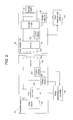
- FIG. 2 is a block diagram illustrating an internal configuration of a power transmission unit and a power reception unit illustrated in FIG. 1 .
- FIG. 3A is a diagram illustrating an equivalent circuit of the power transmission unit and the power reception unit illustrated in FIG. 2 .
- FIG. 3B is a diagram illustrating another equivalent circuit of the power transmission unit and the power reception unit illustrated in FIG. 2 .
- FIG. 3C is a diagram illustrating still another equivalent circuit of the power transmission unit and the power reception unit illustrated in FIG. 2 .
- FIG. 3D is a diagram illustrating still another equivalent circuit of the power transmission unit and the power reception unit illustrated in FIG. 2 .
- FIG. 4A is a diagram illustrating a disposition of coils of the power transmission unit and the power reception unit illustrated in FIG. 1 , in an xy plane.
- FIG. 4B is a diagram illustrating a disposition of the coils of the power transmission unit and the power reception unit illustrated in FIG. 1 , in a yz plane.
- FIG. 4C is a diagram illustrating a disposition of the coils of the power transmission unit and the power reception unit illustrated in FIG. 1 , in an xz plane.
- FIG. 4D is a perspective diagram illustrating a disposition of the coils of the power transmission unit and the power reception unit illustrated in FIG. 1 .
- FIG. 5 is a diagram illustrating a relationship between a phase difference of a primary side current and a primary side voltage, and a driving frequency.
- FIG. 6 is a block diagram illustrating an internal configuration of a power transmission unit and a power reception unit according to Embodiment 2 of the present invention.
- FIG. 7 is a block diagram illustrating another internal configuration of the power transmission unit and the power reception unit.
- FIG. 8 is a block diagram illustrating still another internal configuration of the power transmission unit and the power reception unit.
- FIG. 9A is a diagram illustrating a disposition of coils in the xy plane, when solenoid coils are used for the power transmission unit and the power reception unit.
- FIG. 9B is a diagram illustrating a disposition of the coils in the xz plane, when solenoid coils are used for the power transmission unit and the power reception unit.
- FIG. 9C is a diagram illustrating a disposition of the coils in the yz plane, when solenoid coils are used for the power transmission unit and the power reception unit.
- FIG. 9D is a perspective diagram illustrating the disposition of the coils when solenoid coils are used for the power transmission unit and the power reception unit.
- a gap, axis deviation, a state of charge (SOC), and the like easily change power transmission conditions, and the change causes a phase difference between a primary side current and a primary side voltage to be also changed.
- the frequency may be in a phase advance region.
- a strict restriction condition is applied in order to avoid a phase advance mode (operation in the phase advance region), and a free selection of a driving frequency is not possible.
- a configuration of charging system 10 according to Exemplary embodiment 1 of the present invention will be described with reference to FIG. 1 .
- Charging system 10 includes power transmission device 100 , vehicle 150 , and power transmission-side operation unit 160 .
- FIG. 1 illustrates a state where power transmission coil 103 a and power reception coil 154 a face each other so as to enable power transmission.
- Power transmission device 100 is installed on the ground or buried in the ground, so as to cause power transmission unit 103 to be exposed from the surface g of the earth.
- Power transmission device 100 is provided in a parking space, for example. When vehicle 150 is parked, power transmission device 100 is positioned to face power reception unit 154 , and thus transmits power to power reception unit 154 .
- power transmission refers to an operation that power is supplied to power reception coil 154 a from power transmission coil 103 a.
- a configuration of power transmission device 100 will be described later.
- Vehicle 150 is, for example, an automobile which is referred to as an electric vehicle (EV) or a plug-in electric vehicle (PEV), and travels by using power of storage battery 152 .
- EV electric vehicle
- PEV plug-in electric vehicle
- a configuration of vehicle 150 will be described later.
- An operation from the outside of vehicle 150 causes power transmission-side operation unit 160 to output a power-transmission start signal or a power-transmission stop signal to power transmission device 100 .
- the power-transmission start signal indicates a start of power transmission
- the power-transmission stop signal indicates stop of the power transmission.
- Vehicle 150 is mainly configured from power reception-side operation unit 151 , storage battery 152 , power reception-side controller 153 , power reception unit 154 , and power reception-side communication unit 155 .
- Power reception-side operation unit 151 receives various operations from a user, and outputs various signals depending on the received operation, to power reception-side controller 153 .
- Storage battery 152 accumulates power which has been supplied from power transmission device 100 through power reception unit 154 .
- Power reception-side controller 153 controls power reception unit 154 and power reception-side communication unit 155 to perform various types of processing which relates to charging, or to perform various types of processing which relates to charging stop, based on the various signals which have been input from power reception-side operation unit 151 and power reception unit 154 .
- Power reception-side controller 153 transmits and receives various types of information to and from power transmission-side controller 102 of power transmission device 100 through power reception-side communication unit 155 .
- Power reception unit 154 includes power reception coil 154 a.
- Power reception coil 154 a is, for example, a spiral coil. Power reception coil 154 a receives power which is transmitted from power transmission coil 103 a of power transmission unit 103 .
- Power reception unit 154 supplies power received by power reception coil 154 a to storage battery 152 in accordance with a control of power reception-side controller 153 .
- Power reception unit 154 is provided in a state of being exposed to the outside of vehicle 150 , in the bottom of vehicle 150 .
- Power reception-side communication unit 155 generates a charging permission signal for permitting charging, or a charging nonpermission signal for forbidding charging, in accordance with a control of power reception-side controller 153 .
- Power reception-side communication unit 155 transmits the charging permission signal or the charging nonpermission signal which has been generated, to power transmission-side communication unit 101 .
- the charging nonpermission signal is transmitted, for example, in a case where a position shift is detected during power transmission, or in a case where storage battery 152 is in a state of being fully charged.
- Power transmission device 100 is mainly configured from power transmission-side communication unit 101 , power transmission-side controller 102 , power transmission unit 103 , and storage 104 .
- Power transmission-side communication unit 101 receives the charging permission signal or the charging nonpermission signal from power reception-side communication unit 155 , and outputs the charging permission signal or the charging nonpermission signal which has been received, to power transmission-side controller 102 .
- power transmission-side controller 102 controls power transmission unit 103 to try power transmission to power reception coil 154 a while sequentially changing a frequency for power transmission coil 103 a.
- power transmission-side controller 102 When power transmission is performed on trial, power transmission-side controller 102 obtains a phase difference of a primary side current with respect to a primary side voltage for each frequency, based on the primary side current which flows in power transmission unit 103 , and the primary side voltage which is applied to power transmission unit 103 . Power transmission-side controller 102 stores the obtained phase difference in storage 104 .
- Power transmission-side controller 102 selects a frequency which is drivable at the phase delay region, based on the phase difference of the primary side current with respect to the primary side voltage for each frequency, which has been stored in storage 104 .
- Power transmission-side controller 102 controls power transmission unit 103 to start main power transmission by using the selected frequency.
- power transmission-side controller 102 controls power transmission unit 103 not to start power transmission or to stop the power transmission.
- Power transmission-side controller 102 transmits and receives various types of information to and from power reception-side controller 153 of vehicle 150 through power transmission-side communication unit 101 .
- Power transmission unit 103 includes power transmission coil 103 a .
- Power transmission coil 103 a is, for example, a spiral coil.
- Power transmission unit 103 performs power transmission on trial by using power transmission coil 103 a while sequentially changing a frequency, in accordance with a control of power transmission-side controller 102 . Power transmission unit 103 performs main power transmission at the determined driving frequency.
- Power transmission unit 103 transmits power by using, for example, an electromagnetic induction method, an electric resonance method, or a magnetic resonance method.
- Storage 104 stores the phase difference for each frequency, which has been output from power transmission-side controller 102 .
- FIG. 2 is a block diagram illustrating an internal configuration of power transmission unit 103 and power reception unit 154 illustrated in FIG. 1 .
- Power transmission unit 103 includes power source 201 , power transmission-side inverter 202 , voltage detector 203 , current detector 204 , resonator 205 , and power transmission coil 103 a.
- Power source 201 supplies DC power having a predetermined voltage and a predetermined current to power transmission-side inverter 202 .
- Power transmission-side inverter 202 converts the DC power which has been supplied from power source 201 , into AC power and supplies the converted AC power to resonator 205 and power transmission coil 103 a , in accordance with a control of power transmission-side controller 102 .
- Voltage detector 203 detects a voltage value of the AC power which has been supplied to resonator 205 from power transmission-side inverter 202 , and outputs the detected voltage value to power transmission-side controller 102 .
- Power transmission-side controller 102 obtains a phase of the primary side voltage based on the voltage value which has been output from voltage detector 203 .
- Current detector 204 detects a current value of the AC power which has been supplied to resonator 205 from power transmission-side inverter 202 , and outputs the detected current value to power transmission-side controller 102 .
- Power transmission-side controller 102 obtains a phase of the primary side current based on the current value which has been output from current detector 204 .
- Voltage detector 203 and current detector 204 may detect a voltage value and a current value of power supplied to power transmission-side inverter 202 .
- Resonator 205 is a capacitor which has, for example, a capacitance value C 1 , and resonates with power transmission coil 103 a.
- Power transmission coil 103 a receives the supply of the AC power by power transmission-side inverter 202 , and thus resonates with resonator 205 and transmits power to power reception coil 154 a.
- Power transmission coil 103 a is defined to have an inductance value L 1 .
- Power reception unit 154 includes power reception coil 154 a , resonator 251 , current detector 252 , rectifier circuit 253 , and voltage detector 254 .
- Power reception coil 154 a receives an electromagnetic field (including magnetic flux) occurring by power transmission coil 103 a of power transmission unit 103 , generates an electromotive force, and then supplies the generated electromotive force to resonator 251 .
- Power reception coil 154 a is defined to have an inductance value L 2 .
- a current generated by the electromotive force is referred below to as a power reception-side coil current.
- Resonator 251 is a capacitor which has, for example, a capacitance value C 2 , and resonates with power reception coil 154 a.
- Current detector 252 detects a current value of the power supplied from power reception coil 154 a , and outputs detected current value to power reception-side controller 153 .
- Power reception-side controller 153 obtains a phase of the power reception-side coil current based on the current value which has been output from current detector 252 .
- Rectifier circuit 253 rectifies the power reception-side coil current which has been supplied from power reception coil 154 a , and supplies the current obtained by the rectification, to storage battery 152 .
- Voltage detector 254 detects a voltage value of the DC power which has been supplied to storage battery 152 from rectifier circuit 253 , and outputs the detected voltage value to power reception-side controller 153 .
- Voltage detector 254 may have a configuration in which a voltage value of the power which is supplied to rectifier circuit 253 is detected.
- L 1 C 1 is defined to be a product of the capacitance value C 1 of resonator 205 and the inductance value L 1 of power transmission coil 103 a
- L 2 C 2 is defined to be a product of the capacitance value C 2 of resonator 251 and the inductance value L 2 of power reception coil 154 a
- L 1 , C 1 , L 2 , and C 2 are set to cause L 1 C 1 to be different from L 2 C 2 .
- FIGS. 3A to 3D are diagrams illustrating equivalent circuits of power transmission unit 103 and power reception unit 154 illustrated in FIG. 2 .
- Re 1 indicates a resistor in power transmission unit 103
- Ca 1 indicates a capacitor of resonator 205 in power transmission unit 103
- Le 1 indicates power transmission coil 103 a.
- Le 2 indicates power reception coil 154 a
- Re 2 indicates a wiring resistor in power reception unit 154 and a resistor of rectifier circuit 253
- Ca 2 indicates a capacitor of resonator 251
- FIGS. 3A to 3D illustrate modification examples of a disposition of Ca 1 and Ca 2 .
- FIG. 3A illustrates a circuit configuration in which Ca 1 is disposed to be in parallel with Le 1 , and Ca 2 is disposed to be in parallel with Le 2 .
- FIG. 3B illustrates a circuit configuration in which Ca 1 is disposed to be in series with Le 1 , and Ca 2 is disposed to be in series with Le 2 .
- FIG. 3C illustrates a circuit configuration in which Ca 1 is disposed to be in parallel with Le 1 , and Ca 2 is disposed to be in series with Le 2 .
- FIG. 3D illustrates a circuit configuration in which Ca 1 is disposed to be in series with Le 1 , and Ca 2 is disposed to be in parallel with Le 2 .
- FIGS. 4A to 4D illustrate a state where power transmission coil 103 a and power reception coil 154 a are positioned.
- An x axis indicates a transverse direction of vehicle 150 (a +x direction indicates a rightward direction of vehicle 150 , and a ⁇ x direction indicates a leftward direction of vehicle 150 ).
- a y axis indicates a forth-and-back direction of vehicle 150 (a +y direction indicates the rear of vehicle 150 , and a ⁇ y direction indicates the front of vehicle 150 ).
- a z axis indicates a vertical direction to the ground (a +z direction indicates an upward direction of vehicle 150 , and a ⁇ z direction indicates a downward direction of vehicle 150 ).
- FIG. 4A illustrates the xy plane
- FIG. 4B illustrates the yz plane
- FIG. 4C illustrates the xz plane.
- FIG. 4D is a perspective view illustrating power transmission coil 103 a and power reception coil 154 a.
- flat spiral coils are respectively used for power transmission coil 103 a and power reception coil 154 a , and each of the spiral coils is disposed so as to cause a flat surface thereof to be in parallel with the ground g.
- FIG. 5 is a diagram illustrating a relationship between the phase difference of the primary side current and the primary side voltage, and the driving frequency.
- a vertical axis indicates a phase difference ⁇ Tx of the primary side current and the primary side voltage
- a transverse axis indicates a driving frequency f.
- phase difference ⁇ Tx can be expressed by the following expression (1).
- ⁇ Tx arctan( XTx/RTx ) (1)
- XTx indicates a reactance component obtained by viewing from power transmission unit 103
- RTx indicates a resistance component obtained by viewing from power transmission unit 103 .
- the inductance value and the capacitance value are selected so as to extend the frequency range f in which ⁇ Tx(f) ⁇ 0 is satisfied.
- the minimum value of the function is equal to or more than 0. This point contributes to extension of the frequency range in which ⁇ Tx ⁇ 0 is satisfied.
- the above-described selection method of the inductance value and the capacitance value is just an example.
- the inductance value and the capacitance value may be selected by using other various methods, so as to cause the frequency range f in which ⁇ Tx(f) ⁇ 0 is satisfied to be extended.
- the capacitance value C 1 of resonator 205 , the inductor L 1 of power transmission coil 103 a , the capacitance value C 2 of resonator 251 , and the value of the inductor L 2 of power reception coil 154 a are set so as to cause the frequency range in which the phase difference ⁇ Tx between the primary side current and the primary side voltage is equal to or more than 0 to be extended.
- the capacitance value C 1 of resonator 205 , the inductor L 1 of power transmission coil 103 a , the capacitance value C 2 of resonator 251 , and the value of the inductor L 2 of power reception coil 154 a are set so as to cause the minimum value to be equal to or more than 0.
- the vicinity of the resonant frequency on a low frequency side is easily used as the driving frequency.
- a state where a region in which driving in the phase advance mode is performed is not provided in an area to the vicinity of the resonant frequency on the low frequency side, that is, a state where the minimum value is equal to or more than 0 is preferable.
- FIG. 6 is a block diagram illustrating an internal configuration of power transmission unit 103 and power reception unit 154 according to Exemplary embodiment 2 of the present invention.
- FIG. 6 is different from FIG. 2 in that resonator 205 is replaced with resonant capacity adjuster 301 , resonator 251 is replaced with resonant capacity adjuster 303 , power transmission-side controller 102 is replaced with power transmission-side controller 302 , and power reception-side controller 153 is replaced with power reception-side controller 304 .
- the resonant capacity adjuster 301 is, for example, a variable capacitor which resonates with power transmission coil 103 a.
- power transmission-side controller 302 When power transmission is performed on trial, power transmission-side controller 302 obtains a phase difference of a primary side current with respect to a primary side voltage for each frequency, based on the primary side current which flows in power transmission unit 103 , and the primary side voltage which is applied to power transmission unit 103 . Power transmission-side controller 302 stores the obtained phase difference in storage 104 .
- Power transmission-side controller 302 adjusts the capacitance value C 1 of resonant capacity adjuster 301 .
- Power transmission-side controller 302 notifies power reception-side controller 304 of the phase difference for each frequency, which has been stored in storage 104 , the adjusted capacitance value of resonant capacity adjuster 301 , and the like through power transmission-side communication unit 101 and power reception-side communication unit 155 .
- Power transmission-side controller 302 also has the same function as power transmission-side controller 102 .
- Resonant capacity adjuster 303 is, for example, a variable capacitor which resonates with power reception coil 154 a.
- Power reception-side controller 304 adjusts the capacitance value C 2 of resonant capacity adjuster 303 .
- Power reception-side controller 304 also has the same function as power reception-side controller 153 .
- Power transmission-side controller 302 controls power transmission unit 103 to try power transmission to power reception coil 154 a while sequentially changing a frequency for power transmission coil 103 a.
- power transmission-side controller 302 When power transmission is performed on trial, power transmission-side controller 302 obtains a phase difference of a primary side current from a primary side voltage for each frequency, based on the primary side current which flows in power transmission unit 103 , and the primary side voltage which is applied to power transmission unit 103 . Power transmission-side controller 302 stores the obtained phase difference in storage 104 .
- power transmission-side controller 302 adjusts the capacitance value C 1 of resonant capacity adjuster 301 .
- Power transmission-side controller 302 controls power transmission unit 103 to try power transmission to power reception coil 154 a while sequentially changing a frequency for power transmission coil 103 a , again.
- Power transmission-side controller 302 obtains the phase difference of the primary side current from the primary side voltage, for each frequency, and stores the obtained phase difference in storage 104 .
- Power transmission-side controller 302 repeats to adjust the capacitance value C 1 of resonant capacity adjuster 301 , and to calculate and store the phase difference of the primary side current from the primary side voltage for each frequency.
- the capacitance value C 1 is adjusted so as to be four values of 1.2 ⁇ C 2 , 1.8 ⁇ C 2 , C 2 /1.2, and C 2 /1.8, and the phase difference of the primary side current with respect to the primary side voltage is calculated for each frequency.
- power transmission-side controller 302 specifies a capacitance value which causes the frequency range in which ⁇ Tx ⁇ 0 is satisfied to be widest. Power transmission-side controller 302 adjusts the capacitance value C 1 of resonant capacity adjuster 301 so as to be equal to the specified capacitance value.
- the capacitance value is adjusted so as to be the capacitance value C 1 which causes the frequency range in which the phase difference ⁇ Tx is equal to or more than 0 to become wide, it is possible to improve the degree of freedom in selection of a driving frequency which is drivable in the phase delay region.
- Power transmission-side controller 302 controls power transmission unit 103 to try power transmission to power reception coil 154 a while sequentially changing a frequency for power transmission coil 103 a .
- power transmission-side controller 302 obtains a phase difference of a primary side current with respect to a primary side voltage for each frequency, based on the primary side current which flows in power transmission unit 103 , and the primary side voltage which is applied to power transmission unit 103 .
- Power transmission-side controller 302 stores the obtained phase difference in storage 104 .
- power transmission-side controller 302 instructs power reception-side controller 304 to adjust the capacitance value C 2 of resonant capacity adjuster 303 through power transmission-side communication unit 101 and power reception-side communication unit 155 .
- C 2 1.2 ⁇ initial state C 2 may be set).
- Power transmission-side controller 302 controls power transmission unit 103 to try power transmission to power reception coil 154 a while sequentially changing a frequency for power transmission coil 103 a , again.
- Power transmission-side controller 302 obtains the phase difference of the primary side current with respect to the primary side voltage, for each frequency, and stores the obtained phase difference in storage 104 .
- Adjusting the capacitance value C 2 of resonant capacity adjuster 303 , and calculating and storing the phase difference of the primary side current with respect to the primary side voltage for each frequency are repeatedly performed.
- the capacitance value C 2 is adjusted so as to be four values of 1.2 ⁇ C 1 , 1.8 ⁇ C 1 , C 1 /1.2, and C 1 /1.8, and the phase difference of the primary side current with respect to the primary side voltage is calculated for each frequency.
- power transmission-side controller 302 specifies a capacitance value which causes the frequency range in which ⁇ Tx ⁇ 0 is satisfied to be widest. Power transmission-side controller 302 notifies power reception-side controller 304 of the capacitance value. Power reception-side controller 304 adjusts the capacitance value C 2 of resonant capacity adjuster 303 so as to be equal to the specified capacitance value.
- the capacitance value is adjusted so as to be the capacitance value C 2 which causes the frequency range in which the phase difference ⁇ Tx is equal to or more than 0 to become wide, it is possible to improve the degree of freedom in selection of a driving frequency which is drivable in the phase delay region.
- power transmission-side controller 302 and power reception-side controller 304 may change both of C 1 and C 2 in corporation with each other.
- power transmission-side controller 302 mainly performs a control.
- power reception-side controller 304 may mainly perform the control.
- power transmission device 100 includes storage 104 , and power transmission-side controller 302 calculates the phase difference.
- vehicle 150 may include storage 104 , and power reception-side controller 304 may calculate the phase difference for each frequency, based on the value of the primary side current and the value of the primary side voltage which have been received through power reception-side communication unit 155 .
- a communication unit which communicates with a separate server may be provided, and the server may, for example, calculate and store the phase difference.
- a changed value of the capacitance value C 1 or C 2 depends on a relational expression of C 1 and C 2 . However, a predetermined numerical value may be used as the changed value.
- the phase difference ⁇ Tx which may be changed depending on power transmission conditions such as a gap, axis deviation, a state of charge (SOC), and the like is measured.
- the capacitance value of the resonant capacity adjuster is adjusted so as to cause the frequency range in which the phase difference ⁇ Tx is equal to or more than 0 to become wide, and thus it is possible to improve the degree of freedom in selection of a driving frequency which is drivable in the phase delay region.
- resonant capacity adjuster 301 is provided in power transmission unit 103 and resonant capacity adjuster 303 is provided in power reception unit 154 is described.
- the present invention is not limited thereto, and the resonant capacity adjuster may be provided any one of power transmission unit 103 and power reception unit 154 .
- FIG. 7 illustrates a case where resonant capacity adjuster 301 is provided in power transmission unit 103 .
- FIG. 8 illustrates a case where resonant capacity adjuster 303 is provided in power reception unit 154 .
- each of resonant capacity adjusters 301 and 303 may be configured from a plurality of capacitors which are connected to a switch and have capacitance values different from each other, and the capacitance value may be changed by switching.
- a separate coil may be provided so as to be in series with power transmission coil 103 a and/or power reception coil 154 a .
- a circuit which bypasses the coil and a switch for opening and closing the bypass circuit may be provided. The inductance value may be changed by switching.
- a separate coil having a different inductance value may be provided in parallel with power transmission coil 103 a and/or power reception coil 154 a .
- a switch which performs switching to the coil may be provided, and the inductance value may be changed by switching.
- a configuration in which the capacitance value and the inductance value are changed together may be made.
- Exemplary embodiment 1 and Exemplary embodiment 2 a case where the capacitance value C 1 and the like are set or adjusted so as to cause the frequency range in which the phase difference ⁇ Tx is equal to or more than 0 to be as wide as possible is exemplified.
- the driving frequency may be in the phase delay region (phase difference ⁇ Tx is equal to or more than 0).
- the value may be set or adjusted to be a value (capacitance value C 1 and the like) which causes the driving frequency to be in the phase delay region.
- the value which causes the driving frequency to be in the phase delay region may be provided. It may be not necessary that the value is set or adjusted to be a value which causes the frequency range in which the phase difference ⁇ Tx is equal to or more than 0 to be widest.
- the present invention is not limited thereto, and for example, solenoid coils may be used.
- FIGS. 9A to 9D illustrate states where power transmission coil 103 a and power reception coil 154 a are positioned, and an iron core in the coil will be omitted.
- An x axis indicates a transverse direction of vehicle 150 (a +x direction indicates a rightward direction of vehicle 150 , and a ⁇ x direction indicates a leftward direction of vehicle 150 ).
- a y axis indicates a forth-and-back direction of vehicle 150 (a +y direction indicates the rear of vehicle 150 , and a ⁇ y direction indicates the front of vehicle 150 ).
- a z axis indicates a vertical direction to the ground (a +z direction indicates an upward direction of vehicle 150 , and a ⁇ z direction indicates a downward direction of vehicle 150 ).
- FIG. 9A illustrates the xy plane
- FIG. 9B illustrates the xz plane
- FIG. 9C illustrates the yz plane.
- FIG. 9D is a perspective view illustrating power transmission coil 103 a and power reception coil 154 a.
- solenoid coils which are respectively used for power transmission coil 103 a and power reception coil 154 a are disposed so as to cause the central axis to be in parallel with the ground g.
- the contactless power transmission device, the contactless power reception device, and the contactless power transmission system are useful for improving the degree of freedom in selection of a driving frequency.
Landscapes
- Engineering & Computer Science (AREA)
- Power Engineering (AREA)
- Computer Networks & Wireless Communication (AREA)
- Transportation (AREA)
- Mechanical Engineering (AREA)
- Charge And Discharge Circuits For Batteries Or The Like (AREA)
- Electric Propulsion And Braking For Vehicles (AREA)
- Current-Collector Devices For Electrically Propelled Vehicles (AREA)
Applications Claiming Priority (3)
| Application Number | Priority Date | Filing Date | Title |
|---|---|---|---|
| JP2014089110A JP6464520B2 (ja) | 2014-04-23 | 2014-04-23 | 非接触送電装置、非接触受電装置及び非接触送電システム |
| JP2014-089110 | 2014-04-23 | ||
| PCT/JP2015/001878 WO2015162859A1 (fr) | 2014-04-23 | 2015-04-01 | Dispositif de transmission de puissance sans contact, dispositif de réception de puissance sans contact, et système de transmission de puissance sans contact |
Publications (2)
| Publication Number | Publication Date |
|---|---|
| US20170126067A1 US20170126067A1 (en) | 2017-05-04 |
| US10076966B2 true US10076966B2 (en) | 2018-09-18 |
Family
ID=54332041
Family Applications (1)
| Application Number | Title | Priority Date | Filing Date |
|---|---|---|---|
| US15/301,857 Active 2035-09-18 US10076966B2 (en) | 2014-04-23 | 2015-04-01 | Contactless power transmission device, contactless power reception device, and contactless power transmission system |
Country Status (5)
| Country | Link |
|---|---|
| US (1) | US10076966B2 (fr) |
| EP (1) | EP3136542B1 (fr) |
| JP (1) | JP6464520B2 (fr) |
| CN (1) | CN106233575B (fr) |
| WO (1) | WO2015162859A1 (fr) |
Cited By (8)
| Publication number | Priority date | Publication date | Assignee | Title |
|---|---|---|---|---|
| US11017942B2 (en) * | 2018-11-01 | 2021-05-25 | Witricity Corporation | Systems and methods for determining coil current in wireless power systems |
| US11356079B2 (en) | 2020-01-23 | 2022-06-07 | Witricity Corporation | Tunable reactance circuits for wireless power systems |
| US11489332B2 (en) | 2019-05-24 | 2022-11-01 | Witricity Corporation | Protection circuits for wireless power receivers |
| US11631999B2 (en) | 2020-03-06 | 2023-04-18 | Witricity Corporation | Active rectification in wireless power systems |
| US11695270B2 (en) | 2020-01-29 | 2023-07-04 | Witricity Corporation | Systems and methods for auxiliary power dropout protection |
| US11695300B2 (en) | 2018-11-30 | 2023-07-04 | Witricity Corporation | Systems and methods for low power excitation in high power wireless power systems |
| US11843258B2 (en) | 2019-08-26 | 2023-12-12 | Witricity Corporation | Bidirectional operation of wireless power systems |
| US12100969B2 (en) | 2023-05-31 | 2024-09-24 | Witricity Corporation | Systems and methods for low power excitation in high power wireless power systems |
Families Citing this family (6)
| Publication number | Priority date | Publication date | Assignee | Title |
|---|---|---|---|---|
| KR20170066525A (ko) * | 2014-11-06 | 2017-06-14 | 후지쯔 가부시끼가이샤 | 수전기 및 전력 전송 시스템 |
| US10186908B2 (en) * | 2015-08-04 | 2019-01-22 | Ningbo Weie Electronic Technology Co., Ltd. | Efficient power transmitting terminal, contactless power transmission device and power transmission method |
| US10483836B2 (en) * | 2017-07-31 | 2019-11-19 | Lear Corporation | Method of early hard switching detection and protection for inductive power transfer |
| JP2019062646A (ja) * | 2017-09-26 | 2019-04-18 | 日本無線株式会社 | 非接触給電装置及び非接触給電システム |
| CN110562061B (zh) * | 2019-09-02 | 2021-03-02 | 中兴新能源汽车有限责任公司 | 无线充电车辆端电压控制电路、方法、装置及充电设备 |
| KR102439634B1 (ko) * | 2020-08-27 | 2022-09-05 | 에스케이씨 주식회사 | 무선 전력 수신 장치, 무선 전력 송신 장치 및 무선 전력 송수신 장치 |
Citations (3)
| Publication number | Priority date | Publication date | Assignee | Title |
|---|---|---|---|---|
| US20130035814A1 (en) * | 2011-08-06 | 2013-02-07 | Delphi Technologies, Inc. | Electrical charging system that includes voltage-controlled oscillator which operatively controls wireless electromagnetic or wireless inductive charging of a battery |
| JP2013153627A (ja) | 2012-01-26 | 2013-08-08 | Shindengen Electric Mfg Co Ltd | 非接触給電回路 |
| US20140152117A1 (en) * | 2012-12-03 | 2014-06-05 | WIPQTUS Inc. | Wireless Power System With A Self-regulating Wireless Power Receiver |
Family Cites Families (4)
| Publication number | Priority date | Publication date | Assignee | Title |
|---|---|---|---|---|
| JP5510032B2 (ja) * | 2009-05-14 | 2014-06-04 | 日産自動車株式会社 | 非接触給電装置 |
| US9577715B2 (en) * | 2011-06-17 | 2017-02-21 | Kabushiki Kaisha Toyota Jidoshokki | Resonance-type non-contact power supply system |
| JP5899490B2 (ja) * | 2011-07-20 | 2016-04-06 | パナソニックIpマネジメント株式会社 | 非接触給電システム |
| US20140333150A1 (en) * | 2012-01-26 | 2014-11-13 | Pioneer Corporation | Power transmitting apparatus and power transmitting method |
-
2014
- 2014-04-23 JP JP2014089110A patent/JP6464520B2/ja active Active
-
2015
- 2015-04-01 EP EP15782394.9A patent/EP3136542B1/fr active Active
- 2015-04-01 WO PCT/JP2015/001878 patent/WO2015162859A1/fr active Application Filing
- 2015-04-01 CN CN201580020983.8A patent/CN106233575B/zh active Active
- 2015-04-01 US US15/301,857 patent/US10076966B2/en active Active
Patent Citations (3)
| Publication number | Priority date | Publication date | Assignee | Title |
|---|---|---|---|---|
| US20130035814A1 (en) * | 2011-08-06 | 2013-02-07 | Delphi Technologies, Inc. | Electrical charging system that includes voltage-controlled oscillator which operatively controls wireless electromagnetic or wireless inductive charging of a battery |
| JP2013153627A (ja) | 2012-01-26 | 2013-08-08 | Shindengen Electric Mfg Co Ltd | 非接触給電回路 |
| US20140152117A1 (en) * | 2012-12-03 | 2014-06-05 | WIPQTUS Inc. | Wireless Power System With A Self-regulating Wireless Power Receiver |
Non-Patent Citations (1)
| Title |
|---|
| International Search Report of PCT application No. PCT/JP2015/001878 dated Jun. 30, 2015. |
Cited By (12)
| Publication number | Priority date | Publication date | Assignee | Title |
|---|---|---|---|---|
| US11017942B2 (en) * | 2018-11-01 | 2021-05-25 | Witricity Corporation | Systems and methods for determining coil current in wireless power systems |
| US11695300B2 (en) | 2018-11-30 | 2023-07-04 | Witricity Corporation | Systems and methods for low power excitation in high power wireless power systems |
| US11710985B2 (en) | 2018-11-30 | 2023-07-25 | Witricity Corporation | Systems and methods for low power excitation in high power wireless power systems |
| US11489332B2 (en) | 2019-05-24 | 2022-11-01 | Witricity Corporation | Protection circuits for wireless power receivers |
| US11695271B2 (en) | 2019-05-24 | 2023-07-04 | Witricity Corporation | Protection circuits for wireless power receivers |
| US11843258B2 (en) | 2019-08-26 | 2023-12-12 | Witricity Corporation | Bidirectional operation of wireless power systems |
| US11356079B2 (en) | 2020-01-23 | 2022-06-07 | Witricity Corporation | Tunable reactance circuits for wireless power systems |
| US11695270B2 (en) | 2020-01-29 | 2023-07-04 | Witricity Corporation | Systems and methods for auxiliary power dropout protection |
| US11909198B2 (en) | 2020-01-29 | 2024-02-20 | Witricity Corporation | Gate driver implementations for safe wireless power system operation |
| US11631999B2 (en) | 2020-03-06 | 2023-04-18 | Witricity Corporation | Active rectification in wireless power systems |
| US11888328B2 (en) | 2020-03-06 | 2024-01-30 | Witricity Corporation | Active rectification in wireless power systems |
| US12100969B2 (en) | 2023-05-31 | 2024-09-24 | Witricity Corporation | Systems and methods for low power excitation in high power wireless power systems |
Also Published As
| Publication number | Publication date |
|---|---|
| CN106233575B (zh) | 2019-04-12 |
| EP3136542B1 (fr) | 2019-07-24 |
| EP3136542A1 (fr) | 2017-03-01 |
| JP2015208191A (ja) | 2015-11-19 |
| US20170126067A1 (en) | 2017-05-04 |
| CN106233575A (zh) | 2016-12-14 |
| JP6464520B2 (ja) | 2019-02-06 |
| WO2015162859A1 (fr) | 2015-10-29 |
| EP3136542A4 (fr) | 2017-07-05 |
Similar Documents
| Publication | Publication Date | Title |
|---|---|---|
| US10076966B2 (en) | Contactless power transmission device, contactless power reception device, and contactless power transmission system | |
| EP3311464B1 (fr) | Dispositifs, systèmes et procédés d'utilisation d'une injection de puissance réactive pour des systèmes de charge de véhicule électrique à réglage actif | |
| EP3631945B1 (fr) | Commande de récepteur d'énergie sans fil multimode | |
| KR101317293B1 (ko) | 비접촉 급전 설비, 비접촉 수전 장치 및 비접촉 급전 시스템 | |
| WO2012086051A1 (fr) | Système d'alimentation sans contact, véhicule, unité d'alimentation et procédé de commande de système d'alimentation sans contact | |
| EP3215393A1 (fr) | Systèmes, appareil et procédé pour un transfert de puissance sans fil adaptatif | |
| US20130257167A1 (en) | Apparatuses, systems, and methods for power transfer adjustment in wireless power transfer systems | |
| US20160197487A1 (en) | Wireless power receiving device | |
| JP6089464B2 (ja) | 非接触電力伝送装置 | |
| US10239412B2 (en) | Method and apparatus for wireless charging using variable switching frequency | |
| KR20140018373A (ko) | 비접촉 수전 장치 및 이를 구비한 차량, 비접촉 송전 장치, 및 비접촉 전력 전송 시스템 | |
| US20150061402A1 (en) | Power reception device, power transmission device and power transfer system | |
| US10411525B2 (en) | System and method for frequency prediction | |
| EP3282556B1 (fr) | Système d'alimentation électrique sans contact | |
| JP6176547B2 (ja) | 非接触給電装置及び非接触給電装置の始動方法 | |
| JP7021007B2 (ja) | 非接触受電装置 | |
| JP2020115703A (ja) | 非接触電力伝送システム | |
| JP7444612B2 (ja) | 非接触充電装置及び非接触充電装置の適合方法 | |
| JP7061058B2 (ja) | 受電機器 | |
| WO2015098747A1 (fr) | Dispositif de transmission d'énergie et appareil de transmission d'énergie sans contact | |
| JP2022007549A (ja) | 非接触充電システム | |
| JP2021175286A (ja) | 非接触充電システム | |
| JP2020115702A (ja) | 非接触電力伝送システム | |
| JP2019193431A (ja) | 非接触送電装置 |
Legal Events
| Date | Code | Title | Description |
|---|---|---|---|
| AS | Assignment |
Owner name: PANASONIC INTELLECTUAL PROPERTY MANAGEMENT CO., LT Free format text: ASSIGNMENT OF ASSIGNORS INTEREST;ASSIGNORS:KOIZUMI, MASAYOSHI;OHASHI, OSAMU;OTA, TOMOHIRO;AND OTHERS;SIGNING DATES FROM 20160913 TO 20160920;REEL/FRAME:041085/0391 |
|
| STCF | Information on status: patent grant |
Free format text: PATENTED CASE |
|
| MAFP | Maintenance fee payment |
Free format text: PAYMENT OF MAINTENANCE FEE, 4TH YEAR, LARGE ENTITY (ORIGINAL EVENT CODE: M1551); ENTITY STATUS OF PATENT OWNER: LARGE ENTITY Year of fee payment: 4 |
|
| AS | Assignment |
Owner name: PANASONIC AUTOMOTIVE SYSTEMS CO., LTD., JAPAN Free format text: ASSIGNMENT OF ASSIGNORS INTEREST;ASSIGNOR:PANASONIC INTELLECTUAL PROPERTY MANAGEMENT CO., LTD.;REEL/FRAME:066703/0132 Effective date: 20240207 |