US10076312B2 - Filter assembly for medical image signal and dynamic decimation method using same - Google Patents
Filter assembly for medical image signal and dynamic decimation method using same Download PDFInfo
- Publication number
- US10076312B2 US10076312B2 US15/551,684 US201515551684A US10076312B2 US 10076312 B2 US10076312 B2 US 10076312B2 US 201515551684 A US201515551684 A US 201515551684A US 10076312 B2 US10076312 B2 US 10076312B2
- Authority
- US
- United States
- Prior art keywords
- filter
- decimation
- medical image
- image signal
- mac
- Prior art date
- Legal status (The legal status is an assumption and is not a legal conclusion. Google has not performed a legal analysis and makes no representation as to the accuracy of the status listed.)
- Active
Links
Images
Classifications
-
- A—HUMAN NECESSITIES
- A61—MEDICAL OR VETERINARY SCIENCE; HYGIENE
- A61B—DIAGNOSIS; SURGERY; IDENTIFICATION
- A61B8/00—Diagnosis using ultrasonic, sonic or infrasonic waves
- A61B8/08—Detecting organic movements or changes, e.g. tumours, cysts, swellings
-
- A—HUMAN NECESSITIES
- A61—MEDICAL OR VETERINARY SCIENCE; HYGIENE
- A61B—DIAGNOSIS; SURGERY; IDENTIFICATION
- A61B8/00—Diagnosis using ultrasonic, sonic or infrasonic waves
- A61B8/52—Devices using data or image processing specially adapted for diagnosis using ultrasonic, sonic or infrasonic waves
- A61B8/5269—Devices using data or image processing specially adapted for diagnosis using ultrasonic, sonic or infrasonic waves involving detection or reduction of artifacts
-
- A—HUMAN NECESSITIES
- A61—MEDICAL OR VETERINARY SCIENCE; HYGIENE
- A61B—DIAGNOSIS; SURGERY; IDENTIFICATION
- A61B8/00—Diagnosis using ultrasonic, sonic or infrasonic waves
- A61B8/52—Devices using data or image processing specially adapted for diagnosis using ultrasonic, sonic or infrasonic waves
- A61B8/5207—Devices using data or image processing specially adapted for diagnosis using ultrasonic, sonic or infrasonic waves involving processing of raw data to produce diagnostic data, e.g. for generating an image
-
- G—PHYSICS
- G01—MEASURING; TESTING
- G01S—RADIO DIRECTION-FINDING; RADIO NAVIGATION; DETERMINING DISTANCE OR VELOCITY BY USE OF RADIO WAVES; LOCATING OR PRESENCE-DETECTING BY USE OF THE REFLECTION OR RERADIATION OF RADIO WAVES; ANALOGOUS ARRANGEMENTS USING OTHER WAVES
- G01S15/00—Systems using the reflection or reradiation of acoustic waves, e.g. sonar systems
- G01S15/88—Sonar systems specially adapted for specific applications
- G01S15/89—Sonar systems specially adapted for specific applications for mapping or imaging
- G01S15/8906—Short-range imaging systems; Acoustic microscope systems using pulse-echo techniques
- G01S15/8977—Short-range imaging systems; Acoustic microscope systems using pulse-echo techniques using special techniques for image reconstruction, e.g. FFT, geometrical transformations, spatial deconvolution, time deconvolution
-
- G—PHYSICS
- G01—MEASURING; TESTING
- G01S—RADIO DIRECTION-FINDING; RADIO NAVIGATION; DETERMINING DISTANCE OR VELOCITY BY USE OF RADIO WAVES; LOCATING OR PRESENCE-DETECTING BY USE OF THE REFLECTION OR RERADIATION OF RADIO WAVES; ANALOGOUS ARRANGEMENTS USING OTHER WAVES
- G01S7/00—Details of systems according to groups G01S13/00, G01S15/00, G01S17/00
- G01S7/52—Details of systems according to groups G01S13/00, G01S15/00, G01S17/00 of systems according to group G01S15/00
- G01S7/52017—Details of systems according to groups G01S13/00, G01S15/00, G01S17/00 of systems according to group G01S15/00 particularly adapted to short-range imaging
- G01S7/52023—Details of receivers
- G01S7/52025—Details of receivers for pulse systems
- G01S7/52026—Extracting wanted echo signals
-
- G—PHYSICS
- G01—MEASURING; TESTING
- G01S—RADIO DIRECTION-FINDING; RADIO NAVIGATION; DETERMINING DISTANCE OR VELOCITY BY USE OF RADIO WAVES; LOCATING OR PRESENCE-DETECTING BY USE OF THE REFLECTION OR RERADIATION OF RADIO WAVES; ANALOGOUS ARRANGEMENTS USING OTHER WAVES
- G01S7/00—Details of systems according to groups G01S13/00, G01S15/00, G01S17/00
- G01S7/52—Details of systems according to groups G01S13/00, G01S15/00, G01S17/00 of systems according to group G01S15/00
- G01S7/52017—Details of systems according to groups G01S13/00, G01S15/00, G01S17/00 of systems according to group G01S15/00 particularly adapted to short-range imaging
- G01S7/52046—Techniques for image enhancement involving transmitter or receiver
-
- H—ELECTRICITY
- H03—ELECTRONIC CIRCUITRY
- H03H—IMPEDANCE NETWORKS, e.g. RESONANT CIRCUITS; RESONATORS
- H03H17/00—Networks using digital techniques
- H03H17/02—Frequency selective networks
- H03H17/06—Non-recursive filters
- H03H17/0621—Non-recursive filters with input-sampling frequency and output-delivery frequency which differ, e.g. extrapolation; Anti-aliasing
- H03H17/0635—Non-recursive filters with input-sampling frequency and output-delivery frequency which differ, e.g. extrapolation; Anti-aliasing characterized by the ratio between the input-sampling and output-delivery frequencies
- H03H17/065—Non-recursive filters with input-sampling frequency and output-delivery frequency which differ, e.g. extrapolation; Anti-aliasing characterized by the ratio between the input-sampling and output-delivery frequencies the ratio being integer
- H03H17/0664—Non-recursive filters with input-sampling frequency and output-delivery frequency which differ, e.g. extrapolation; Anti-aliasing characterized by the ratio between the input-sampling and output-delivery frequencies the ratio being integer where the output-delivery frequency is lower than the input sampling frequency, i.e. decimation
Definitions
- the present invention relates to a technique of receiving and processing a medical image signal and, more particularly, a filter assembly for adaptively processing variation in bandwidth of an ultrasound image signal received from a probe according to depth of an image, and a dynamic decimation method using the same.
- Medical imaging technology is a diagnosis technique of visually representing muscles, tendons, and many internal organs, to capture their size, structure, and pathologic lesions with real-time tomographic images, based on an ultrasound or photoacoustic means. Medical imaging is also used to visualize fetuses during a periodic checkup or in an emergency situation. Ultrasound has been used to image the interior of the human body for at least 50 years and has become one of the most widely used diagnostic tools in modern medicine. The ultrasound technique is low in cost and easy in mobility, relative to magnetic resonance imaging (MRI) or X-ray computed tomography (CT).
- MRI magnetic resonance imaging
- CT X-ray computed tomography
- the principle of ultrasound imaging is as follows. First, an ultrasound image is made by bringing a measurement object into contact with a probe and receiving ultrasound reflected by generation of ultrasound waves. If ultrasound is generated, an ultrasound wave passes into a medium within a very short time and the ultrasound wave is reflected upon passing between two media having different acoustic impedances. In the ultrasound imaging technique, such a reflection wave is measured and a distance is calculated based on the time until reflection sound returns back, thereby achieving imaging.
- the technical objects that can be achieved through the present invention are designed to solve inefficiency of a conventional filter structure for implementing dynamic decimation, in which filter length increases in proportion to a decimation ratio and thus there are wasted filters and multipliers that are not used according to dynamic variation of the decimation ratio and solve overhead of hardware cost and the amount of calculations necessary for multiplication at a high data rate because all multipliers are positioned after an expander.
- a filter assembly for a medical image signal including an expander configured to receive the medical image signal and up-sample the medical image signal; and a decimation filter including an integer number of multiplier accumulators (MACs), configured to change a cutoff frequency according to bandwidth of the received medical image signal by dynamically updating an impulse response and perform decimation on the up-sampled signal according to a decimation ratio.
- MACs multiplier accumulators
- the decimation filter may calculate a partial sum, which is the sum of coefficients of a k-th (wherein k is a positive integer) location of a polyphase filter, through each MAC.
- Each MAC may include a shift register configured to receive and store coefficients of a polyphase filter, a multiplier configured to multiply the coefficients stored in the shift register by the up-sampled signal, a summer configured to cumulatively sum the multiplied results, and a decimator configured to decimate the summed result.
- a frequency band of the received signal may be determined by attenuation caused by depth of an object of the medical image signal and filter coefficients for calculating different cutoff frequencies according to the depth may be supplied to the MAC through the shift register to control a signal-to-noise ratio of the medical image.
- Each MAC may include a fixed number of multipliers regardless of the decimation ratio to prevent waste of multipliers used according to variation in filter length.
- a filter assembly for a medical image signal including a decimation filter including an integer number of multiplier accumulators (MACs), configured to change a cutoff frequency according to bandwidth of the medical image signal by dynamically updating an impulse response and perform decimation on the received signal according to a decimation ratio, wherein the decimation filter determines a filter coefficient adjusted by an interval of an integer number to up-sample the medical image signal and supplies the filter coefficient to each MAC.
- MACs multiplier accumulators
- the medical image signal supplied to the decimation filter may not be previously up-sampled and operate at a low frequency relative to a previously up-sampled signal.
- the decimation filter may determine, in consideration of an integer-fold expander for up-sampling, the filter coefficient so as to perform a partial sum calculation of the signal through the MAC except for a zero padding part out of an output of the expander.
- the decimation filter may calculate a partial sum, which is the sum of coefficients of a k-th (where k is a positive integer) location of a polyphase filter, through the MAC.
- the MAC may include a shift register configured to receive and store coefficients of a polyphase filter; a multiplier configured to multiply the coefficients stored in the shift register by the medical image signal; a summer configured to cumulatively sum the multiplied results; and a decimator configured to perform decimation on the summed result.
- a method of decimating a medical image signal including receiving the medical image signal; selecting a filter coefficient for changing a cutoff frequency according to bandwidth of the medical image signal in consideration of a decimation ratio; supplying the selected filter coefficient to a partial sum calculator including an integer number of multiplier accumulators (MACs); and performing, by the partial sum calculator, dynamic decimation on the received medical image signal, using the selected filter coefficient, wherein the filter coefficient is determined in consideration of an interval of an integer number to up-sample the received medical image signal.
- MACs multiplier accumulators
- the medical image signal supplied to the partial sum calculator may not be previously up-sampled and operate at a low frequency relative to a previously up-sampled signal.
- the selecting the filter coefficient may include determining, in consideration of an integer-fold expander for up-sampling, the filter coefficient so as to calculate a partial sum through each MAC except for a zero padding part out of an output of the expander.
- the partial sum calculator may calculate a partial sum, which is the sum of coefficients of a k-th (where k is a positive integer) location of a polyphase filter, through each MAC.
- the performing dynamic decimation may includes multiplying, by the MAC, the medical image signal by coefficients of a polyphase filter stored in a shift register by use of a multiplier; cumulatively summing, by the MAC, the multiplied results by use of a summer; and decimating, by the MAC, the summed result by use of a decimator.
- the MAC may include a fixed number of multipliers regardless of the decimation ratio to prevent waste of multipliers used according to variation in filter length.
- Embodiments of the present invention require relatively fewer hardware resources and less power consumption upon performing dynamic decimation by implementing a fixed number of multipliers by a polyphase filter structure and can achieve ultra-slimness of an ultrasound imaging system by adaptively applying a cutoff frequency of a filter in order to raise SNR.
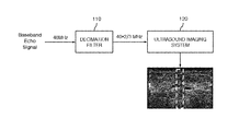
- FIG. 1 is a diagram for explaining a decimation filter used in a medical imaging system through which embodiments of the present invention are implemented.
- FIG. 2 is a diagram for explaining problems occurring upon dynamically performing decimation through a finite impulse response (FIR) filter.
- FIR finite impulse response
- FIG. 3 is a diagram for explaining an example of implementing a decimation filter using a polyphase structure instead of the FIR filter of FIG. 2 and problems occurring in such an example.
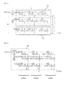
- FIG. 4 is a diagram illustrating a decimation filter assembly implementing partial sums of phase filters using multiplier accumulators (MACs) according to an embodiment of the present invention.
- MACs multiplier accumulators
- FIG. 5 is a block diagram illustrating in detail a partial sum calculator for calculating a k-th (wherein k is a positive integer) partial sum in the decimation filter assembly of FIG. 4 according to an embodiment of the present invention.
- FIGS. 6A and 6B are diagrams for explaining a structure in which an expander is removed from the decimation filter assembly of FIG. 4 .
- FIG. 7 is a block diagram for explaining a structure in which an expander is removed according to another embodiment of the present invention.
- FIG. 8 is a flowchart illustrating a decimation method of a medical image signal using a dynamic decimation filter according to still another embodiment of the present invention.
- a filter assembly for a medical image signal includes an expander configured to receive the medical image signal and up-sample the medical image signal; and a decimation filter including an integer number of multiplier accumulators (MACs), configured to change a cutoff frequency according to bandwidth of the medical image signal by dynamically updating an impulse response and perform decimation on the up-sampled signal according to a decimation ratio.
- MACs multiplier accumulators
- N denotes the length of a filter
- D denotes a delay
- L denotes expansion increasing rate of an expander for up-sampling
- M denotes a decimation ratio
- FIG. 1 is a diagram for explaining a decimation filter used in a medical imaging system through which embodiments of the present invention are implemented.
- a dynamic filter is used to maximize SNR as frequency bandwidth decreases and is mainly implemented by a decimation filter used generally to match the data rate of the echo signal to a screen. Accordingly, such a dynamic decimation filter should be capable of performing decimation on an arbitrary fractional decimation factor M/L and should be capable of dynamically updating an impulse response thereof.
- a decimation filter 110 adjusts the number of samples when the number of samples of a baseband signal is larger than the number of samples to be displayed on a screen through an ultrasound imaging system 120 .
- an input signal x(n) is integer-fold up-sampled ( 111 ), signal-processed using a coefficient ( 112 ) of a decimation filter, and decimated ( 113 ) at a ratio of M, thereby generating an output signal y(n).
- the echo signal in medical ultrasound imaging is affected by depth-dependent attenuation and the bandwidth of the echo signal differs according to depth. Therefore, it is necessary to dynamically update a cutoff frequency with respect to each depth in order to maximize SNR. That is, the cutoff frequency varies with bandwidth using the dynamic filter.
- the length N of the filter is proportional to the cutoff frequency and the decimation ratio.
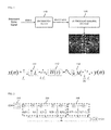
- FIG. 2 is a diagram for explaining problems occurring upon dynamically performing decimation through a finite impulse response (FIR) filter.
- FIR finite impulse response
- the filter length N is equal to the number of multipliers included in the filter and, due to characteristics of the dynamic decimation filter structure, a hardware filter should be implemented for a maximum decimation ratio.
- the multipliers operate at a high operation frequency of L times and at a high data rate of L times. Therefore, the amount of calculations per unit time increases and thus overhead increases in terms of the amount of calculations of a block and hardware cost.
- FIG. 3 is a diagram for explaining an example of implementing a decimation filter using a polyphase structure instead of the FIR filter of FIG. 2 and problems occurring in such an example.
- a dynamic decimation filter using a polyphase filter may be used.
- M-fold decimation is performed after performing L-fold expansion.
- the filter of FIG. 3 has the same length as the filter of FIG. 2 but a data rate at which multipliers operate is lowered by M times.
- embodiments of the present invention described hereinbelow propose a filter structure which has all functions of the above-described dynamic decimation filter and simultaneously can be efficiently implemented without waste of hardware and operation resources. That is, an efficient arbitrary factional decimation structure only using K multiplier accumulators is proposed to use restricted hardware complexity regardless of L and K.
- Equation 1 An equation of a general FIR-based decimation filter is defined as follows.
- M/L an arbitrary fractional decimation factor
- Equation 1 a signal w(n) which is L-fold up-sampled with respect to an input x(n) is given as indicated in Equation 1.
- Equation 2 A procedure of filtering the FIR as shown in FIG. 2 with respect to such an input is indicated as Equation 2.
- h(j) denotes a coefficient of a given FIR filter and N denotes the length of the filter.
- Equation 2 may be summarized as Equation 3 upon changing a dynamic decimation filter structure to a polyphase structure in which outputs of all polyphase filters are added as illustrated in FIG. 3 .
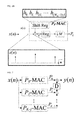
- FIG. 4 is a diagram illustrating a structure in which partial sums P 0 to P k-1 are added based on k-th coefficients with respect to M polyphase filters of FIG. 3 .
- FIG. 4 is a diagram illustrating rearrangement of the polyphase filters of FIG. 3 through multiplier accumulators (MACs) according to an embodiment of the present invention. It may be appreciated that the polyphase filters are implemented through a plurality of P 0 -MAC, P 1 -MAC, . . . , P k -MAC connected in parallel to each other.
- MACs multiplier accumulators
- Equation 3 indicates that each partial sum P k (n) in FIG. 4 is obtained by multiplying M consecutive pairs of input samples by filter coefficients at a data rate of L ⁇ f x and cumulatively summing the multiplied results. Since each partial sum is calculated at a period of M samples through Equation 3, it will be appreciated that the partial sum can be implemented by a single MAC. Outputs of the MACs are summed to produce an output y(n) as indicated by Equation 4.
- Each MAC that calculates each partial sum P k (n) is represented as P k -MAC and all P k -MAC units receive the same data set. This is implemented by eliminating delays between adjacent filter blocks illustrated in FIG. 3 and, instead, outputs of the MAC units are implemented as a delayed sum as indicated in Equation 4.
- the filter assembly of FIG. 4 includes an expander for receiving a medical image signal and up-sampling the medical image signal and a decimation filter that includes an integer number of MACs, changes a cutoff frequency according to bandwidth of the medical image signal by dynamically updating an impulse response, and performs decimation on the up-sampled signal according to a decimation ratio.
- the decimation filter calculates a partial sum, which is the sum of coefficients of a k-th (wherein k is a positive integer) location of a polyphase filter, using each MAC.
- calculation can be performed using only K (where K is a positive integer) multipliers using the MAC, as opposed to the multipliers used to match the filter length as in FIGS. 2 and 3 . Therefore, if only the length of the coefficients supplied to the MAC is matched as the filter length varies, arbitrary fractional decimation can be performed only by a limited number of multipliers.
- the amount of ultrasound reception signals varies according to depth of an image. For example, if the amount of reception data used to image a specific depth is 1,536, 1,024 samples are required to display the specific depth at a resolution of 640 ⁇ 480. Therefore, 3/2-fold decimation is needed.
- a filter coefficient is updated in the shift register by calculating a different cutoff frequency according to depth, a filter having a maximum SNR can be constructed.
- FIG. 5 is a block diagram illustrating in detail a partial sum calculator 400 for calculating a k-th (wherein k is a positive integer) partial sum in the decimation filter assembly of FIG. 4 according to an embodiment of the present invention.
- the partial sum calculator 400 includes an expander 410 and a P k -MAC 420 .
- Each P k -MAC cumulatively sums filter calculations with respect to an L-fold up-sampled input signal and outputs the summed result according to a decimation ratio.
- M filter coefficient calculations are performed by one multiplier.
- a filter coefficient of a shift register is adaptively applied according to the cutoff frequency.
- the P k -MAC 420 includes a shift register 421 for receiving and storing coefficients of a polyphase filter, a multiplier 422 for multiplying the coefficients stored in the shift register 421 by the up-sampled signal, a summer and register 423 for cumulatively summing the multiplied results, and a decimator 424 for performing M-fold decimation on the summed result.
- the frequency band of the reception signal is determined by attenuation caused by the depth of an object of the medical image signal.
- the P k -MAC 420 calculates different cutoff frequencies according to the depth and supplies the filter coefficients to the shift register 421 , thereby controlling an SNR of the medical image. Particularly, since the P k -MAC 420 includes a fixed number of multipliers 422 regardless of the decimation ratio, the waste of multipliers used according to variation in the filter length is prevented.
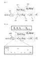
- FIG. 6 is a diagram for explaining a structure in which an expander is removed from the decimation filter assembly of FIG. 4 .
- (a) of FIG. 6 corresponds to the filter structure introduced in FIGS. 4 and 5 .
- a medical image signal input to a Pk-MAC is a signal which is L-fold up-sampled by an expander 610 . That is, it may be appreciated that the structure of (a) of FIG. 6 demands L-fold expansion with respect to input data.
- a filter assembly for the medical image signal illustrated in (b) of FIG. 6 includes a decimation filter which includes an integer number of MACs, changes a cutoff frequency according to bandwidth of the medical image signal by dynamically updating an impulse response, and performs decimation on the received signal according to a decimation ratio.
- the decimation filter selects filter coefficients adjusted by an interval of an integer number in order to up-sample the medical image signal and supplies the selected filter coefficients to the MAC.
- the medical image signal supplied to the decimation filter of (b) of FIG. 6 is not previously up-sampled and operates at a low frequency relative to a previously up-sampled signal.
- the decimation filter determines the filter coefficients such that the MAC may perform a partial sum calculation of a signal except for a zero padding part out of the output of the expander. That is, if the filter coefficients are adjusted to values other than 0 out of the output of the expander in consideration of the L-fold expander and are adaptively supplied to the MAC to match frequency bandwidth, the expander may be eliminated and a cutoff frequency matching input frequency bandwidth may be adaptively applied.
- the decimation filter of (b) of FIG. 6 also calculates a partial sum, which is the sum of coefficients of a k-th (where k is a positive integer) location of a polyphase filter, through the MAC.
- the MAC includes a shift register for receiving and storing the coefficients of the polyphase filter, a multiplier for multiplying the coefficients stored in the shift register by the medical image signal, a summer for cumulatively summing the multiplied results, and a decimator for performing decimation on the summed result.
- the decimation filter assembly of (b) of FIG. 6 requires fewer hardware resources and less power consumption by operating at a relatively low frequency and can prevent waste of multipliers according to variation of the filter length by using a fixed number of multipliers regardless of a decimation ratio.
- FIG. 7 is a block diagram illustrating a decimation filter assembly in which an expander is removed according to another embodiment of the present invention.
- a partial sum of a phase filter structure is implemented using MACs.
- l denotes the smallest value of p and ⁇ circumflex over (n) ⁇ denotes the largest value of q
- X ( n ) [ x ( ⁇ circumflex over ( n ) ⁇ ) x ( ⁇ circumflex over (n) ⁇ 1) . . . x ( ⁇ circumflex over (n) ⁇ M n +1)] T
- H k ( l ) [ h ( kM+l ) h ( kM+l+L ) . . . h ( kM+l ( M n ⁇ 1) L )] T [Equation 6]
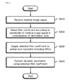
- FIG. 8 is a flowchart illustrating a decimation method of a medical image signal using a dynamic decimation filter according to still another embodiment of the present invention. Since the decimation method includes a procedure corresponding to each configuration of (b) of FIG. 6 described earlier, each process will be briefly described focusing on a time cause-and-effect relation of operations to avoid a repeated description.
- step S 810 a medical image signal is received.
- a filter coefficient for changing a cutoff frequency is selected according to bandwidth of the medical image signal in consideration of a decimation ratio.
- the filter coefficient in order to remove an expander, is desirably determined in consideration of an interval of an integer number for up-sampling the medical image signal received in step S 810 .
- the medical image signal supplied to a partial sum calculator is not previously up-sampled and operates at a low frequency relative to a previously up-sampled signal.
- step S 830 the determined filter coefficient is supplied to the partial sum calculator including an integer number of MACs.
- the partial sum calculator calculates a partial sum, which is the sum of coefficients of a k-th (where k is a positive integer) location of a polyphase filter, using the MAC.
- the MAC includes a fixed number of multipliers regardless of the decimation ratio, thereby preventing waste of multipliers according to variation in filter length.
- step S 840 dynamic decimation is performed on the received medical image signal using the filter coefficients supplied by the partial sum calculator. More specifically, in step S 840 , the MAC multiplies the medical image signal by the coefficients of the polyphase filter stored in a shift register, by use of a multiplier, and cumulatively sums the multiplied results, and decimates the summed result using a decimator.
- the method for performing decimation on a medical image signal in processing a digital signal may be implemented as code that can be written in a computer-readable recording medium and thus read by a computer system.
- the computer-readable recording medium may be any type of recording device in which data that can be read by the computer system is stored.
- Examples of the computer-readable recording medium include a ROM, a RAM, a CD-ROM, a magnetic tape, a floppy disk, optical data storage, and a carrier wave (e.g., data transmission over the Internet).
- the computer-readable recording medium can be distributed over computer systems connected to a network so that computer-readable code is written thereto and executed therefrom in a decentralized manner.
- Functional programs, code, and code segments to realize the embodiments herein can be construed by one of ordinary skill in the art.
- a fixed number of multipliers is implemented as a polyphase filter structure using a MAC. Therefore, since relatively few hardware resources and less power consumption are needed upon performing dynamic decimation and a cutoff frequency of a filter is adaptively applied to raise SNR, ultra-slimness of an ultrasound imaging system can be achieved.
Abstract
Description
X(n)=[x({circumflex over (n)})x({circumflex over (n)}−1) . . . x({circumflex over (n)}−M n+1)]T,
H k(l)=[h(kM+l)h(kM+l+L) . . . h(kM+l(M n−1)L)]T [Equation 6]
Claims (18)
Applications Claiming Priority (3)
| Application Number | Priority Date | Filing Date | Title |
|---|---|---|---|
| KR10-2015-0023981 | 2015-02-17 | ||
| KR1020150023981A KR101613521B1 (en) | 2015-02-17 | 2015-02-17 | Filter Assembly for medical image signal and dynamic decimation method using thereof |
| PCT/KR2015/013122 WO2016133274A2 (en) | 2015-02-17 | 2015-12-03 | Filter assembly for medical image signal and dynamic decimation method using same |
Publications (2)
| Publication Number | Publication Date |
|---|---|
| US20180035981A1 US20180035981A1 (en) | 2018-02-08 |
| US10076312B2 true US10076312B2 (en) | 2018-09-18 |
Family
ID=56021679
Family Applications (1)
| Application Number | Title | Priority Date | Filing Date |
|---|---|---|---|
| US15/551,684 Active US10076312B2 (en) | 2015-02-17 | 2015-12-03 | Filter assembly for medical image signal and dynamic decimation method using same |
Country Status (4)
| Country | Link |
|---|---|
| US (1) | US10076312B2 (en) |
| KR (1) | KR101613521B1 (en) |
| DE (1) | DE112015006183T5 (en) |
| WO (1) | WO2016133274A2 (en) |
Families Citing this family (4)
| Publication number | Priority date | Publication date | Assignee | Title |
|---|---|---|---|---|
| JP6840016B2 (en) * | 2017-04-07 | 2021-03-10 | 株式会社日立製作所 | Ultrasonic diagnostic equipment and ultrasonic diagnostic system |
| KR102087266B1 (en) | 2017-11-30 | 2020-03-10 | 서강대학교산학협력단 | Filter assembly for ultra sound image signal and method and device for interlaced beam focusing using thereof |
| US10685445B2 (en) * | 2018-06-09 | 2020-06-16 | Uih-Rt Us Llc | Systems and methods for generating augmented segmented image set |
| KR102462997B1 (en) * | 2020-11-04 | 2022-11-02 | 국방과학연구소 | Synthetic aperture radar and decimation method for synthetic aperture radar data |
Citations (12)
| Publication number | Priority date | Publication date | Assignee | Title |
|---|---|---|---|---|
| US5914922A (en) * | 1997-12-12 | 1999-06-22 | Cirrus Logic, Inc. | Generating a quadrature seek signal from a discrete-time tracking error signal and a discrete-time RF data signal in an optical storage device |
| KR20000014092A (en) | 1998-08-17 | 2000-03-06 | 윤종용 | Interpolation filter and decimation filter |
| JP2000254122A (en) | 1999-03-12 | 2000-09-19 | Ge Yokogawa Medical Systems Ltd | Method and device for forming reception signal and method and device for picking-up ultrasonic wave image |
| US20020031113A1 (en) * | 2000-07-07 | 2002-03-14 | Dodds David E. | Extended distribution of ADSL signals |
| KR20040023927A (en) | 2002-09-12 | 2004-03-20 | 엘지전자 주식회사 | Digtal filter using polyphase |
| KR20080042729A (en) | 2006-11-09 | 2008-05-15 | 요코가와 덴키 가부시키가이샤 | Decimation filter |
| KR20110022440A (en) | 2009-08-27 | 2011-03-07 | 서강대학교산학협력단 | The apparatus of beamforming the ultrasound signal and the method using it |
| JP2012182722A (en) | 2011-03-02 | 2012-09-20 | Nec Engineering Ltd | Decimation filter and decimation processing method |
| US20130109969A1 (en) | 2011-10-31 | 2013-05-02 | Samsung Electronics Co., Ltd. | Sampling method, apparatus, probe, reception beamforming apparatus, and medical imaging system performing the sampling method |
| KR101315891B1 (en) | 2012-07-17 | 2013-10-14 | 숭실대학교산학협력단 | Recursive half-band filter, and method for fitering using the filter |
| KR20140099567A (en) | 2013-01-31 | 2014-08-13 | (주)루먼텍 | A wideband variable bandwidth channel filter and its filtering method |
| US20170077938A1 (en) * | 2015-09-16 | 2017-03-16 | Semiconductor Components Industries, Llc | Low-power conversion between analog and digital signals using adjustable feedback filter |
-
2015
- 2015-02-17 KR KR1020150023981A patent/KR101613521B1/en active IP Right Grant
- 2015-12-03 WO PCT/KR2015/013122 patent/WO2016133274A2/en active Application Filing
- 2015-12-03 US US15/551,684 patent/US10076312B2/en active Active
- 2015-12-03 DE DE112015006183.5T patent/DE112015006183T5/en not_active Ceased
Patent Citations (13)
| Publication number | Priority date | Publication date | Assignee | Title |
|---|---|---|---|---|
| US5914922A (en) * | 1997-12-12 | 1999-06-22 | Cirrus Logic, Inc. | Generating a quadrature seek signal from a discrete-time tracking error signal and a discrete-time RF data signal in an optical storage device |
| KR20000014092A (en) | 1998-08-17 | 2000-03-06 | 윤종용 | Interpolation filter and decimation filter |
| JP2000254122A (en) | 1999-03-12 | 2000-09-19 | Ge Yokogawa Medical Systems Ltd | Method and device for forming reception signal and method and device for picking-up ultrasonic wave image |
| US20020031113A1 (en) * | 2000-07-07 | 2002-03-14 | Dodds David E. | Extended distribution of ADSL signals |
| KR20040023927A (en) | 2002-09-12 | 2004-03-20 | 엘지전자 주식회사 | Digtal filter using polyphase |
| KR20080042729A (en) | 2006-11-09 | 2008-05-15 | 요코가와 덴키 가부시키가이샤 | Decimation filter |
| JP2008124593A (en) | 2006-11-09 | 2008-05-29 | Yokogawa Electric Corp | Decimation filter |
| KR20110022440A (en) | 2009-08-27 | 2011-03-07 | 서강대학교산학협력단 | The apparatus of beamforming the ultrasound signal and the method using it |
| JP2012182722A (en) | 2011-03-02 | 2012-09-20 | Nec Engineering Ltd | Decimation filter and decimation processing method |
| US20130109969A1 (en) | 2011-10-31 | 2013-05-02 | Samsung Electronics Co., Ltd. | Sampling method, apparatus, probe, reception beamforming apparatus, and medical imaging system performing the sampling method |
| KR101315891B1 (en) | 2012-07-17 | 2013-10-14 | 숭실대학교산학협력단 | Recursive half-band filter, and method for fitering using the filter |
| KR20140099567A (en) | 2013-01-31 | 2014-08-13 | (주)루먼텍 | A wideband variable bandwidth channel filter and its filtering method |
| US20170077938A1 (en) * | 2015-09-16 | 2017-03-16 | Semiconductor Components Industries, Llc | Low-power conversion between analog and digital signals using adjustable feedback filter |
Also Published As
| Publication number | Publication date |
|---|---|
| KR101613521B1 (en) | 2016-05-02 |
| WO2016133274A2 (en) | 2016-08-25 |
| WO2016133274A3 (en) | 2017-05-18 |
| DE112015006183T5 (en) | 2017-11-09 |
| US20180035981A1 (en) | 2018-02-08 |
Similar Documents
| Publication | Publication Date | Title |
|---|---|---|
| US10371804B2 (en) | Ultrasound signal processing circuitry and related apparatus and methods | |
| TWI643601B (en) | Ultrasonic imaging compression methods and apparatus | |
| US10076312B2 (en) | Filter assembly for medical image signal and dynamic decimation method using same | |
| US20110301464A1 (en) | Home ultrasound system | |
| EP3466343B1 (en) | Pulse doppler ultrahigh spectrum resolution imaging processing method and processing system | |
| JP5865050B2 (en) | Subject information acquisition device | |
| KR101971620B1 (en) | Method for sampling, apparatus, probe, beamforming apparatus for receiving, and medical imaging system performing the same | |
| US6704438B1 (en) | Apparatus and method for improving the signal to noise ratio on ultrasound images using coded waveforms | |
| KR20110022440A (en) | The apparatus of beamforming the ultrasound signal and the method using it | |
| US10575825B2 (en) | Doppler imaging | |
| US7504828B2 (en) | Frequency synthesizer for RF pulses, MRI apparatus and RF pulse generating method | |
| JP4698003B2 (en) | Ultrasonic diagnostic equipment | |
| EP2386873A1 (en) | Ultrasonic diagnostic apparatus | |
| CN101461720B (en) | Method and device for regulating measuring range of movement velocity based on spectral Doppler | |
| Zhou et al. | Anefficient quadrature demodulator for medical ultrasound imaging | |
| JP3806229B2 (en) | Ultrasonic diagnostic equipment | |
| JP6697609B2 (en) | Ultrasonic diagnostic device, image processing device, and image processing method | |
| JP2002186615A (en) | Ultrasonic daignostic device | |
| KR101441195B1 (en) | Ultrasonic diagnosis device and signal processing device calculating spectrum, centroid and method for calculating spectrum centroid | |
| JPH11347035A (en) | Ultrasonic diagnostic device | |
| Gao | Efficient digital beamforming for medical ultrasound imaging | |
| JP2017086292A (en) | Ultrasound image diagnostic apparatus |
Legal Events
| Date | Code | Title | Description |
|---|---|---|---|
| FEPP | Fee payment procedure |
Free format text: ENTITY STATUS SET TO SMALL (ORIGINAL EVENT CODE: SMAL); ENTITY STATUS OF PATENT OWNER: SMALL ENTITY |
|
| AS | Assignment |
Owner name: SOGANG UNIVERSITY RESEARCH FOUNDATION, KOREA, REPU Free format text: ASSIGNMENT OF ASSIGNORS INTEREST;ASSIGNORS:SONG, TAI-KYONG;KANG, HYUNGIL;KANG, JEEUN;REEL/FRAME:043899/0094 Effective date: 20170825 |
|
| AS | Assignment |
Owner name: HANSONO CO. LTD, KOREA, REPUBLIC OF Free format text: ASSIGNMENT OF ASSIGNORS INTEREST;ASSIGNOR:SOGANG UNIVERSITY RESEARCH FOUNDATION;REEL/FRAME:044986/0836 Effective date: 20180109 |
|
| STCF | Information on status: patent grant |
Free format text: PATENTED CASE |
|
| MAFP | Maintenance fee payment |
Free format text: PAYMENT OF MAINTENANCE FEE, 4TH YR, SMALL ENTITY (ORIGINAL EVENT CODE: M2551); ENTITY STATUS OF PATENT OWNER: SMALL ENTITY Year of fee payment: 4 |