US10075306B2 - Echo detection circuit and method for multi-carrier system - Google Patents
Echo detection circuit and method for multi-carrier system Download PDFInfo
- Publication number
- US10075306B2 US10075306B2 US15/435,592 US201715435592A US10075306B2 US 10075306 B2 US10075306 B2 US 10075306B2 US 201715435592 A US201715435592 A US 201715435592A US 10075306 B2 US10075306 B2 US 10075306B2
- Authority
- US
- United States
- Prior art keywords
- impulse response
- channel impulse
- circuit
- value
- values
- Prior art date
- Legal status (The legal status is an assumption and is not a legal conclusion. Google has not performed a legal analysis and makes no representation as to the accuracy of the status listed.)
- Expired - Fee Related
Links
Images


Classifications
-
- H—ELECTRICITY
- H04—ELECTRIC COMMUNICATION TECHNIQUE
- H04L—TRANSMISSION OF DIGITAL INFORMATION, e.g. TELEGRAPHIC COMMUNICATION
- H04L27/00—Modulated-carrier systems
- H04L27/26—Systems using multi-frequency codes
- H04L27/2601—Multicarrier modulation systems
- H04L27/2647—Arrangements specific to the receiver only
- H04L27/2649—Demodulators
- H04L27/26524—Fast Fourier transform [FFT] or discrete Fourier transform [DFT] demodulators in combination with other circuits for demodulation
-
- H—ELECTRICITY
- H04—ELECTRIC COMMUNICATION TECHNIQUE
- H04L—TRANSMISSION OF DIGITAL INFORMATION, e.g. TELEGRAPHIC COMMUNICATION
- H04L25/00—Baseband systems
- H04L25/02—Details ; arrangements for supplying electrical power along data transmission lines
- H04L25/0202—Channel estimation
- H04L25/0212—Channel estimation of impulse response
- H04L25/0216—Channel estimation of impulse response with estimation of channel length
-
- H—ELECTRICITY
- H04—ELECTRIC COMMUNICATION TECHNIQUE
- H04J—MULTIPLEX COMMUNICATION
- H04J11/00—Orthogonal multiplex systems, e.g. using WALSH codes
- H04J11/0023—Interference mitigation or co-ordination
- H04J11/0063—Interference mitigation or co-ordination of multipath interference, e.g. Rake receivers
-
- H—ELECTRICITY
- H04—ELECTRIC COMMUNICATION TECHNIQUE
- H04L—TRANSMISSION OF DIGITAL INFORMATION, e.g. TELEGRAPHIC COMMUNICATION
- H04L25/00—Baseband systems
- H04L25/02—Details ; arrangements for supplying electrical power along data transmission lines
- H04L25/0202—Channel estimation
- H04L25/0212—Channel estimation of impulse response
-
- H—ELECTRICITY
- H04—ELECTRIC COMMUNICATION TECHNIQUE
- H04L—TRANSMISSION OF DIGITAL INFORMATION, e.g. TELEGRAPHIC COMMUNICATION
- H04L25/00—Baseband systems
- H04L25/02—Details ; arrangements for supplying electrical power along data transmission lines
- H04L25/0202—Channel estimation
- H04L25/0224—Channel estimation using sounding signals
- H04L25/0228—Channel estimation using sounding signals with direct estimation from sounding signals
- H04L25/023—Channel estimation using sounding signals with direct estimation from sounding signals with extension to other symbols
- H04L25/0232—Channel estimation using sounding signals with direct estimation from sounding signals with extension to other symbols by interpolation between sounding signals
-
- H—ELECTRICITY
- H04—ELECTRIC COMMUNICATION TECHNIQUE
- H04L—TRANSMISSION OF DIGITAL INFORMATION, e.g. TELEGRAPHIC COMMUNICATION
- H04L27/00—Modulated-carrier systems
- H04L27/26—Systems using multi-frequency codes
- H04L27/2601—Multicarrier modulation systems
- H04L27/2626—Arrangements specific to the transmitter only
- H04L27/2627—Modulators
- H04L27/2628—Inverse Fourier transform modulators, e.g. inverse fast Fourier transform [IFFT] or inverse discrete Fourier transform [IDFT] modulators
-
- H—ELECTRICITY
- H04—ELECTRIC COMMUNICATION TECHNIQUE
- H04L—TRANSMISSION OF DIGITAL INFORMATION, e.g. TELEGRAPHIC COMMUNICATION
- H04L27/00—Modulated-carrier systems
- H04L27/26—Systems using multi-frequency codes
- H04L27/2601—Multicarrier modulation systems
- H04L27/2647—Arrangements specific to the receiver only
Definitions
- the invention relates in general to an echo detection circuit and method, and more particularly to an echo detection circuit and method for a multi-carrier system.
- Echo is a common issue that a multi-carrier system frequently encounters.
- the position and channel length of echo need to be correctly estimated.
- the size of a channel impulse response (CIR) is compared with a constant threshold, and the position of the channel impulse response is deemed a position of echo when the size of the channel impulse response is greater than the threshold.
- the constant threshold likely incurs misjudgment. For example, a high threshold may cause smaller echo in a channel impulse response that is then neglected, and a low threshold may cause noise to be misjudged as echo in a channel impulse response to result in an increased data error rate at a receiver.
- the predetermined channel impulse response value may also be too large, such that the threshold in the predetermined range may be too high and cause the foregoing issue of misjudgment.
- the invention is directed to an echo detection circuit and method for a multi-carrier system to accurate detect echo and enhance circuit performance.
- the present invention discloses an echo detection circuit for a multi-carrier system.
- the echo detection circuit include: memory, storing a plurality of channel impulse response values of the multi-carrier system, the channel impulse response values including a target channel impulse response value, a plurality of preceding channel impulse response values and a plurality of subsequent channel impulse response values; a threshold generating circuit, coupled to the memory, generating a threshold corresponding to the target channel impulse response value according to the preceding channel impulse response values and the subsequent channel impulse response values; and an echo determining circuit, coupled to the threshold generating circuit and the memory, comparing the target channel impulse response value with the threshold to determine whether the target channel impulse response value corresponds to an echo path of the multi-carrier system.
- the present invention further discloses an echo detection method for a multi-carrier system.
- the echo detection method includes: storing a plurality of channel impulse response values of the multi-carrier system, the channel impulse response values including a target channel impulse response value, a plurality of preceding channel impulse response values and a plurality of subsequent channel impulse response values; generating a threshold corresponding to the target channel impulse response value according to the preceding channel impulse response values and the subsequent channel impulse response values; and comparing the target channel impulse response value with the threshold to determine whether the target channel impulse response value corresponds to an echo path of the multi-carrier system.
- the echo detection circuit and method for a multi-carrier system of the present invention are capable of adaptively adjusting the threshold according to current channel impulse response values. As opposed to the prior art, the echo detection circuit and method for a multi-carrier system of the present invention are more flexible and are capable of more accurately determining echo.
- FIG. 1 is a partial block diagram of a multi-carrier system of the present invention
- FIG. 2 is a block diagram of an echo detection circuit for a multi-carrier system according to an embodiment of the present invention
- FIG. 3 is a flowchart of an echo detection method for a multi-carrier system corresponding to FIG. 2 according to an embodiment of the present invention
- FIG. 4 is a block diagram of a threshold generating circuit according to an embodiment of the present invention.
- FIG. 5 is a detailed process of step S 320 in an echo detection method for a multi-carrier system according to an embodiment of the present invention
- FIG. 6 is a schematic diagram of a relationship between a channel impulse response value and a channel impulse response index
- FIG. 7 is a block diagram of a threshold generating circuit according to another embodiment of the present invention.
- FIG. 8 is a detailed process of step S 320 in an echo detection method for a multi-carrier system according to another embodiment of the present invention.
- FIG. 9 is a schematic diagram of a relationship between another channel impulse response value and a channel impulse response index
- FIG. 10 is a block diagram of an echo determining circuit according to an embodiment of the present invention.
- FIG. 11 is a detailed process of step S 330 in an echo detection method for a multi-carrier system according to an embodiment of the present invention.
- the disclosure of the application includes an echo detection circuit for a multi-carrier system and a method thereof.
- one person skilled in the art can choose equivalent elements or steps to realize the present invention; that is, the implementation of the present invention is not limited to the non-limiting embodiments below.
- the present invention may be applied to various types of multi-carrier systems, e.g., an orthogonal frequency-division multiplexing (OFDM) multi-carrier system.
- an OFDM multi-carrier system may be a Digital Video Broadcasting-Terrestrial (DVB-T) television system, such as a television system based on DVB-T2, DVB-C2, DTMB and ISDBT specifications.
- DVD-T Digital Video Broadcasting-Terrestrial
- the present invention further refers to the predetermined channel impulse response as well as multiple preceding and subsequent channel impulse responses to dynamically determine the threshold, and thus effectively prevents the issues of a constant threshold.
- FIG. 1 shows a partial block diagram of a multi-carrier system of the present invention.
- a fast Fourier transform (FFT) circuit 1 transforms an input signal to the frequency domain.
- a channel frequency response (CFR) calculating circuit 2 calculates a channel frequency response of a predetermined pilot signal (e.g., a scattered pilot) in the frequency domain.
- a time-domain interpolating circuit 3 performs interpolation in the time domain according to channel frequency responses of pilot signals to obtain channel frequency responses of multiple OFDM signals among the pilot signals.
- a frequency-domain interpolating circuit 4 performs interpolation in the frequency domain according to the channel frequency responses of the pilot signals to obtain channel frequency responses of multiple sub-carriers among the pilot signals.
- the frequency-domain interpolating circuit 4 needs to learn the channel length and an echo position of the multi-carrier system.
- An inverse fast Fourier transform (IFFT) circuit 5 transforms the channel frequency response to a channel impulse response (CIR).
- An echo detection circuit 6 obtains the foregoing channel length and echo position by detecting the channel impulse response in the time domain.
- IFFT inverse fast Fourier transform
- CIR channel impulse response
- FIG. 2 shows a block diagram of the echo detection circuit 6 for a multi-carrier system according to an embodiment of the present invention.
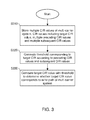
- FIG. 3 shows a flowchart of an echo detection method for a multi-carrier system corresponding to FIG. 2 according to an embodiment of the present invention.
- the echo detection circuit 6 according to the embodiment of the present invention includes a memory 10 , a threshold generating circuit 20 and an echo determining circuit 30 .
- the memory 10 e.g. a register
- channel impulse response values include a target channel impulse response value CIR[k], a plurality of preceding channel impulse response values before the target channel impulse response value and a plurality of subsequent channel impulse response values after the target channel impulse response value (step S 310 ).
- the size of the memory 10 may be designed to sufficiently store a size N of an IFFT window (assuming that N is a positive integer, and 0 ⁇ k ⁇ N ⁇ 1), for example.
- the threshold generating circuit 20 generates a threshold according to channel impulse response values. More specifically, the threshold generating circuit 20 generates a threshold corresponding to the target channel impulse response value CIR[k] according to the preceding channel impulse response values and the subsequent channel impulse response values (step S 320 ).
- the echo determining circuit 30 compares the target channel impulse response value CIR[k] with the threshold to determine whether the target channel impulse response value CIR[k] corresponds to an echo path of the multi-carrier system (step S 330 ).
- FIG. 4 shows a block diagram of the threshold generating circuit 20 according to an embodiment of the present invention.
- FIG. 5 shows a detailed process of step S 320 in the echo detection method for a multi-carrier system according to an embodiment of the present invention.
- the threshold generating circuit 20 includes a calculating circuit 210 , a filtering circuit 220 , a filtering circuit 230 , a detecting circuit 240 and a determining circuit 250 .
- the threshold generating circuit 20 is generating a threshold that is associated with the target channel impulse response value CIR[k], and such object may be achieved though filtering L preceding channel impulse response values of the target channel impulse response value CIR[k] by the filtering circuit 220 and filtering L subsequent channel impulse response values of the target channel impulse response value CIR[k] by the filtering circuit 230 , where L is the size of filtering windows of the filtering circuits 220 and 230 .
- the calculating circuit 210 generates a first reference value according to a maximum value of the N channel impulse response values CIR (step S 510 ).
- the first reference value is equal to R times of the maximum channel impulse response value (0 ⁇ R ⁇ 1).
- the filtering circuits 220 and 230 may be moving average calculating circuits, each including a buffer unit capable of storing at least (L ⁇ 1) channel impulse response values.
- FIG. 6 shows a schematic diagram of a relationship between a channel impulse response value and a channel impulse response index.
- the filtering circuit 220 filters the L preceding channel impulse response values (located in a filtering window 620 ) before the target channel impulse response value CIR[k], and the filtering circuit 230 filters the L subsequent channel impulse response values (located in a filtering window 630 ) after the target channel impulse response value CIR[k].
- the filtering function is realized by moving average calculating circuits
- inputs of the filtering circuits 220 and 230 are respectively (k ⁇ 1) th and (k+L) th channel impulse response values.
- the filtering circuits 220 and 230 generate a second reference value and a third reference value according to an average of a sum of the L channel impulse response values, respectively (steps S 520 and S 530 ).
- the detecting circuit 240 determines whether outputs of the filtering circuit 220 and the filtering circuit 230 are stable according to whether a counter value (generated by a counter (not shown)) is greater than or equal to a predetermined value. More specifically, when the index k of the target channel impulse response value CIR[k] is smaller than L, the respective buffer units in the filtering circuit 220 and the filtering circuit 230 are not yet filled with channel impulse response values, and the second and third references values cannot reflect conditions of the multi-carrier system at this point. Thus, if the determining circuit 250 determines the threshold according to such second and third reference values, an inadequately small threshold may be obtained in a way that system misjudgment may be caused.
- the detecting circuit 240 determines that the outputs of the filtering circuit 220 and the filtering circuit 230 are not yet stable (the determination result of step S 540 is negative, and the detecting circuit 240 does not generate an indication signal), and the determining circuit 250 generates the threshold according to the first reference value (step S 550 ), e.g., directly using the first reference value as the threshold.
- the second reference value is a result of a filtering calculation that the filtering circuit 220 performs on the L channel impulse response values corresponding to channel impulse response indices 0 to (k ⁇ 1)
- the third reference value is a result of a filtering calculation that the filtering circuit 230 performs on the L channel impulse response values corresponding to channel impulse response indices (k+1) to (k+L).
- the detecting circuit 240 determines that the outputs of the filtering circuit 220 and the filtering circuit 230 are stable (the determination result of step S 540 is affirmative, and the detecting circuit 240 generates the indication signal).
- the detecting circuit 250 generates the threshold according to the indication signal, and the first, second and third reference signals (step S 560 ). For example, the determining circuit 250 obtains a minimum value from the first reference value, ⁇ times the second reference value and ⁇ times the third reference value as the threshold ( ⁇ , ⁇ >1, where ⁇ and ⁇ may be equal or different).
- FIG. 7 shows a block diagram of the threshold generating circuit 20 according to another embodiment of the present invention.
- FIG. 8 shows a detailed process of step S 320 in the echo detection method for a multi-carrier system according to another embodiment of the present invention.
- the threshold generating circuit 20 includes a calculating circuit 210 , a filtering circuit 220 , a filtering circuit 230 , a detecting circuit 240 , a selecting circuit 260 , a selecting circuit 270 and a determining circuit 280 . Circuits with the same denotations as those in the embodiment in FIG. 4 have identical functions, and associated details shall be omitted herein. One difference of the embodiment from the embodiment in FIG.
- the filtering circuit 220 and the filtering circuit 230 respectively filter outputs from the selecting circuits 260 and the selecting circuit 270 instead of directly filtering the channel impulse response value CIR. More specifically, after the calculating circuit 210 generates the first reference value (step S 810 ), the selecting circuit 260 individually compares the preceding L channel impulse response values CIR[k ⁇ 1] to CIR[k ⁇ L] of the target channel impulse response value CIR[k] with the first reference value, and outputs L first median values, which are respectively the smaller between the L channel impulse response values CIR[k ⁇ 1] to CIR[k ⁇ L] and the first reference value (step S 820 ).
- the filtering circuit 220 then filters the first median values to generate a second reference value (step S 830 ).
- the selecting circuit 270 individually compares the subsequent channel impulse response values CIR[k+1] to CIR[k+L] of the target channel impulse response value CIR[k] with the first reference value, and outputs L second median values, which are respectively the smaller between the L channel impulse response values CIR[k+1] to CIR[k+L] and the first reference value (step S 840 ).
- the filtering circuit 230 then filters the second median values to generate a third reference value (step S 850 ).
- the detecting circuit 240 determines that the outputs of the filtering circuit 220 and the filtering circuit 230 are not yet stable (the determination result of step S 860 is negative, and the detecting circuit 240 does not generate an indication signal).
- the determining circuit 280 generates a threshold according to the first threshold (step S 870 ), and steps S 820 to S 870 are iterated until the counter value is greater than or equal to the predetermined value.
- the detecting circuit 240 determines that the outputs of the filtering circuit 220 and the filtering circuit 230 are stable (the determination result of step S 860 is affirmative, and the detecting circuit 240 generates the indication signal).
- the determining circuit 280 generates the threshold according to the indication signal as well as the second and third reference values (step S 880 ). For example, the determining circuit 280 obtains a smaller value between ⁇ times the second reference value and ⁇ times the third reference value as the threshold ( ⁇ , ⁇ >1, where ⁇ and ⁇ may be equal or different).
- the filtering circuits 220 and 230 are moving average calculating circuits.
- the outputs of the filtering circuit 220 and the filtering circuit 230 may not become small enough in time as subsequent channel impulse response values get smaller, hence leading to misjudgment.
- the values to be inputted into the filtering circuit 220 and the filtering circuit 230 are first limited to be smaller than or equal to the first reference value, and so the issues of the embodiment in FIG.
- FIG. 9 shows a schematic diagram of a relationship between another channel impulse response value and a channel impulse response index.
- a threshold 910 (the straight segment) is a constant value (e.g., equal to the first threshold), and a threshold 920 (the curved segments at the sides of a channel impulse response value 930 ) is the smaller between ⁇ times the second reference value and ⁇ times of the third reference value. If filtering is not performed by the selecting circuit 260 and the selecting circuit 270 , the threshold 920 may be pulled up by the channel impulse response value 930 , which may then cause a channel impulse response value 940 to be less than the threshold 920 , such that the system may misjudge that the channel impulse response value 940 does not correspond to an echo path. Further, as seen in FIG. 9 , using the threshold 910 in a constant value may also lead to misjudgment (a high threshold may miss the channel impulse response value 940 ).
- FIG. 10 shows a block diagram of the echo determining circuit 30 according to an embodiment of the present invention.
- FIG. 11 shows a detailed process of step S 330 of the echo detection method for a multi-carrier system according to an embodiment of the present invention.
- the echo determining circuit 30 includes a memory 1010 (e.g. a register), a determining circuit 1020 , a counter 1030 , a memory 1040 (e.g. a register) and a determining circuit 1050 .
- the memory 1010 stores a candidate channel impulse response value (having a default value 0) and a corresponding channel impulse response index.
- the determining circuit 1020 compares the target channel impulse response value CIR[k] with the threshold and the candidate channel impulse response (step S 1110 ).
- the determining circuit 1020 regards the target channel impulse response value CIR[k] as a candidate channel impulse response value at this point, stores the candidate channel impulse response value (CIR[k]) and the corresponding channel impulse response index (k) to the memory 1010 (step S 1120 ), and resets the counter 1030 (step S 1130 ).
- the determining circuit 1020 continues comparing the next target channel impulse response value CIR[k+1] with the threshold and the candidate channel impulse response value CIR[k] (iterating step S 1110 ). More specifically, the purpose of the echo determining circuit 30 is comparing the candidate channel impulse response value currently stored in the memory 1010 with M preceding and M subsequent channel impulse response values of the candidate channel impulse response value, where M ⁇ 1. When the current candidate channel impulse response value is the largest among the 2 M+1 (i.e., a comparison range of the determining circuit 1020 ) channel impulse response values, the determining circuit 1020 determines that the candidate channel impulse response is a echo channel impulse response value corresponding to an echo path, and stores the echo channel impulse response value and the corresponding channel impulse response index to the memory 1040 . Conversely, the determining circuit 1020 determines that the candidate channel impulse response value does not correspond to an echo path, and determines whether the comparison range ends according to the counter value of the counter 1030 .
- step S 1110 determines whether the candidate channel impulse response value is larger than the M preceding channel impulse response values.
- the determining circuit 1020 controls the counter 1030 to re-count.
- the counter 1030 continues counting to M (i.e., step S 1110 and step S 1140 are iterated until the determination result of step S 1140 is affirmative), it means that there are M consecutive channel impulse response values smaller than one of the threshold and the candidate channel impulse response value, and so the counter 1030 generates a control signal to notify the determining circuit 1020 .
- the determining circuit 1020 confirms that the candidate channel impulse response value is larger than the M subsequent channel impulse response values according to the control signal, and thus determines the candidate channel impulse response value as an echo channel impulse response value (step S 1150 ), resets the counter 1030 (step S 1160 ), and clears the memory 1010 (step S 1170 ).
- the memory 1040 stores a plurality of echo channel impulse response values and the corresponding channel impulse response indices, and the determining circuit 1050 may then calculate the number of echo path and a channel length of the multi-carrier system according to the contents stored in the memory 1040 .
- the determining circuit 1020 may determine whether the target channel impulse response value CIR[k] is a candidate channel impulse response value and whether the candidate channel impulse response value is an echo channel impulse response value in a parallel or simultaneously manner. That is, instead of having to first identify all of the candidate channel impulse response values and then determine echo channel impulse response values from these candidate channel impulse response values, a plurality of echo channel impulse response values may be determined after the echo determining circuit 30 finishes inspecting all of the N channel impulse response values, thereby enhancing the performance of the circuit.
- the present invention dynamically determines a threshold with reference to the predetermined channel impulse response and multiple preceding and multiple subsequent channel impulse responses of the predetermined channel impulse response. Further, when calculating the moving average of the multiple preceding and multiple subsequent channel impulse responses by moving average calculating circuits to generate the threshold, the threshold may be pulled up due to excessively large maximum values of certain channel impulse response values. Therefore, in the present invention, the selecting circuit 260 and the selecting circuit 270 are used to select input values of the filtering circuit 220 and the filtering circuit 230 to prevent these maximum values from being considered in the moving average calculation, thereby improving the foregoing drawback.
Abstract
Description
Claims (18)
Applications Claiming Priority (3)
| Application Number | Priority Date | Filing Date | Title |
|---|---|---|---|
| TW105132157 | 2016-10-05 | ||
| TW105132157A TWI635732B (en) | 2016-10-05 | 2016-10-05 | Echo detection circuit for multi-carrier system and method thereof |
| TW105132157A | 2016-10-05 |
Publications (2)
| Publication Number | Publication Date |
|---|---|
| US20180097662A1 US20180097662A1 (en) | 2018-04-05 |
| US10075306B2 true US10075306B2 (en) | 2018-09-11 |
Family
ID=61759072
Family Applications (1)
| Application Number | Title | Priority Date | Filing Date |
|---|---|---|---|
| US15/435,592 Expired - Fee Related US10075306B2 (en) | 2016-10-05 | 2017-02-17 | Echo detection circuit and method for multi-carrier system |
Country Status (2)
| Country | Link |
|---|---|
| US (1) | US10075306B2 (en) |
| TW (1) | TWI635732B (en) |
Citations (2)
| Publication number | Priority date | Publication date | Assignee | Title |
|---|---|---|---|---|
| US7292621B2 (en) * | 2001-05-08 | 2007-11-06 | Siemens Aktiengesellschaft | Method for detecting multipath signals |
| US20080112475A1 (en) * | 2006-11-14 | 2008-05-15 | Jun Ma | Detecting channel impulse magnitude response in digital communication systems |
Family Cites Families (2)
| Publication number | Priority date | Publication date | Assignee | Title |
|---|---|---|---|---|
| US9391813B2 (en) * | 2007-02-16 | 2016-07-12 | Maxlinear, Inc. | Long echo detection and channel estimation for OFDM systems |
| US8135339B2 (en) * | 2008-12-31 | 2012-03-13 | Andrew Llc | System and method for feedback cancellation in repeaters |
-
2016
- 2016-10-05 TW TW105132157A patent/TWI635732B/en not_active IP Right Cessation
-
2017
- 2017-02-17 US US15/435,592 patent/US10075306B2/en not_active Expired - Fee Related
Patent Citations (2)
| Publication number | Priority date | Publication date | Assignee | Title |
|---|---|---|---|---|
| US7292621B2 (en) * | 2001-05-08 | 2007-11-06 | Siemens Aktiengesellschaft | Method for detecting multipath signals |
| US20080112475A1 (en) * | 2006-11-14 | 2008-05-15 | Jun Ma | Detecting channel impulse magnitude response in digital communication systems |
Also Published As
| Publication number | Publication date |
|---|---|
| TWI635732B (en) | 2018-09-11 |
| TW201815143A (en) | 2018-04-16 |
| US20180097662A1 (en) | 2018-04-05 |
Similar Documents
| Publication | Publication Date | Title |
|---|---|---|
| CN105791198B (en) | Impulse noise suppression method and OFDM receiver | |
| CN106899393B (en) | Noise variance estimation and interference detection | |
| US8605806B2 (en) | Schemes for detecting guard intervals in OFDM system | |
| JP2012170074A (en) | Method and apparatus for offset estimation in mobile communication system | |
| CN109921826B (en) | Pulse interference suppression method and device | |
| US8073064B2 (en) | Robust FFT trigger point tracking for echo channels in OFDM based communication systems | |
| US10075306B2 (en) | Echo detection circuit and method for multi-carrier system | |
| US20180034731A1 (en) | Device and method for handling effective path of channel impulse response | |
| CN107979550B (en) | Echo detection circuit and method for multi-carrier system | |
| JP6492506B2 (en) | Sequence synchronization apparatus, method and receiver | |
| US9596045B2 (en) | Method for determining impulsive interference applicable to orthogonal frequency division multiple access signal receiver and receiver thereof | |
| US9825732B1 (en) | Signal processing method and circuit for suppressing co-channel interference | |
| US10686514B2 (en) | Wireless receiving device and desired signal detection method | |
| EP2982088A1 (en) | Coarse timing | |
| US20190074856A1 (en) | Symbol rate estimating device and method and adjacent channel interference detecting device | |
| CN108075993B (en) | Method for adaptively adjusting filter coefficient and processing circuit thereof | |
| KR101628649B1 (en) | Pilot frequency sequence determination | |
| US9699005B2 (en) | Echo discriminating device and method thereof | |
| KR20110029652A (en) | Apparatus and method for estimating channel in broadband wireless communication system | |
| JP5777564B2 (en) | Digital broadcast receiver | |
| US9674005B1 (en) | Device and method for handling channel estimation | |
| US9571306B2 (en) | Device and method for eliminating channel effect | |
| CN104753840A (en) | Receiving method of orthogonal frequency-division multiple access signals and receiver | |
| US10171186B2 (en) | Method and device for detecting notch band | |
| US20180098019A1 (en) | Signal processing device and signal processing method of television receiving end |
Legal Events
| Date | Code | Title | Description |
|---|---|---|---|
| AS | Assignment |
Owner name: MSTAR SEMICONDUCTOR, INC., TAIWAN Free format text: ASSIGNMENT OF ASSIGNORS INTEREST;ASSIGNORS:WANG, KUN-YU;LAI, KO-YIN;TUNG, TAI-LAI;REEL/FRAME:041285/0744 Effective date: 20170206 |
|
| STCF | Information on status: patent grant |
Free format text: PATENTED CASE |
|
| AS | Assignment |
Owner name: MEDIATEK INC., TAIWAN Free format text: MERGER;ASSIGNOR:MSTAR SEMICONDUCTOR, INC.;REEL/FRAME:052931/0468 Effective date: 20190115 |
|
| AS | Assignment |
Owner name: XUESHAN TECHNOLOGIES INC., CANADA Free format text: ASSIGNMENT OF ASSIGNORS INTEREST;ASSIGNOR:MEDIATEK INC.;REEL/FRAME:056593/0167 Effective date: 20201223 |
|
| FEPP | Fee payment procedure |
Free format text: MAINTENANCE FEE REMINDER MAILED (ORIGINAL EVENT CODE: REM.); ENTITY STATUS OF PATENT OWNER: LARGE ENTITY |
|
| LAPS | Lapse for failure to pay maintenance fees |
Free format text: PATENT EXPIRED FOR FAILURE TO PAY MAINTENANCE FEES (ORIGINAL EVENT CODE: EXP.); ENTITY STATUS OF PATENT OWNER: LARGE ENTITY |
|
| STCH | Information on status: patent discontinuation |
Free format text: PATENT EXPIRED DUE TO NONPAYMENT OF MAINTENANCE FEES UNDER 37 CFR 1.362 |
|
| FP | Lapsed due to failure to pay maintenance fee |
Effective date: 20220911 |