US10074346B2 - Display control apparatus and method to control a transparent display - Google Patents
Display control apparatus and method to control a transparent display Download PDFInfo
- Publication number
- US10074346B2 US10074346B2 US15/160,720 US201615160720A US10074346B2 US 10074346 B2 US10074346 B2 US 10074346B2 US 201615160720 A US201615160720 A US 201615160720A US 10074346 B2 US10074346 B2 US 10074346B2
- Authority
- US
- United States
- Prior art keywords
- display
- transparent display
- transparent
- viewpoint
- head mounted
- Prior art date
- Legal status (The legal status is an assumption and is not a legal conclusion. Google has not performed a legal analysis and makes no representation as to the accuracy of the status listed.)
- Active
Links
Images


Classifications
-
- G—PHYSICS
- G09—EDUCATION; CRYPTOGRAPHY; DISPLAY; ADVERTISING; SEALS
- G09G—ARRANGEMENTS OR CIRCUITS FOR CONTROL OF INDICATING DEVICES USING STATIC MEANS TO PRESENT VARIABLE INFORMATION
- G09G5/00—Control arrangements or circuits for visual indicators common to cathode-ray tube indicators and other visual indicators
- G09G5/36—Control arrangements or circuits for visual indicators common to cathode-ray tube indicators and other visual indicators characterised by the display of a graphic pattern, e.g. using an all-points-addressable [APA] memory
- G09G5/38—Control arrangements or circuits for visual indicators common to cathode-ray tube indicators and other visual indicators characterised by the display of a graphic pattern, e.g. using an all-points-addressable [APA] memory with means for controlling the display position
-
- G—PHYSICS
- G06—COMPUTING; CALCULATING OR COUNTING
- G06F—ELECTRIC DIGITAL DATA PROCESSING
- G06F3/00—Input arrangements for transferring data to be processed into a form capable of being handled by the computer; Output arrangements for transferring data from processing unit to output unit, e.g. interface arrangements
- G06F3/002—Specific input/output arrangements not covered by G06F3/01 - G06F3/16
- G06F3/005—Input arrangements through a video camera
-
- G—PHYSICS
- G06—COMPUTING; CALCULATING OR COUNTING
- G06F—ELECTRIC DIGITAL DATA PROCESSING
- G06F3/00—Input arrangements for transferring data to be processed into a form capable of being handled by the computer; Output arrangements for transferring data from processing unit to output unit, e.g. interface arrangements
- G06F3/01—Input arrangements or combined input and output arrangements for interaction between user and computer
- G06F3/011—Arrangements for interaction with the human body, e.g. for user immersion in virtual reality
- G06F3/012—Head tracking input arrangements
-
- G—PHYSICS
- G06—COMPUTING; CALCULATING OR COUNTING
- G06F—ELECTRIC DIGITAL DATA PROCESSING
- G06F3/00—Input arrangements for transferring data to be processed into a form capable of being handled by the computer; Output arrangements for transferring data from processing unit to output unit, e.g. interface arrangements
- G06F3/01—Input arrangements or combined input and output arrangements for interaction between user and computer
- G06F3/011—Arrangements for interaction with the human body, e.g. for user immersion in virtual reality
- G06F3/013—Eye tracking input arrangements
-
- G—PHYSICS
- G09—EDUCATION; CRYPTOGRAPHY; DISPLAY; ADVERTISING; SEALS
- G09G—ARRANGEMENTS OR CIRCUITS FOR CONTROL OF INDICATING DEVICES USING STATIC MEANS TO PRESENT VARIABLE INFORMATION
- G09G3/00—Control arrangements or circuits, of interest only in connection with visual indicators other than cathode-ray tubes
- G09G3/001—Control arrangements or circuits, of interest only in connection with visual indicators other than cathode-ray tubes using specific devices not provided for in groups G09G3/02 - G09G3/36, e.g. using an intermediate record carrier such as a film slide; Projection systems; Display of non-alphanumerical information, solely or in combination with alphanumerical information, e.g. digital display on projected diapositive as background
- G09G3/003—Control arrangements or circuits, of interest only in connection with visual indicators other than cathode-ray tubes using specific devices not provided for in groups G09G3/02 - G09G3/36, e.g. using an intermediate record carrier such as a film slide; Projection systems; Display of non-alphanumerical information, solely or in combination with alphanumerical information, e.g. digital display on projected diapositive as background to produce spatial visual effects
-
- G02B27/2214—
-
- G02B27/26—
-
- G—PHYSICS
- G02—OPTICS
- G02B—OPTICAL ELEMENTS, SYSTEMS OR APPARATUS
- G02B30/00—Optical systems or apparatus for producing three-dimensional [3D] effects, e.g. stereoscopic images
- G02B30/20—Optical systems or apparatus for producing three-dimensional [3D] effects, e.g. stereoscopic images by providing first and second parallax images to an observer's left and right eyes
- G02B30/22—Optical systems or apparatus for producing three-dimensional [3D] effects, e.g. stereoscopic images by providing first and second parallax images to an observer's left and right eyes of the stereoscopic type
- G02B30/25—Optical systems or apparatus for producing three-dimensional [3D] effects, e.g. stereoscopic images by providing first and second parallax images to an observer's left and right eyes of the stereoscopic type using polarisation techniques
-
- G—PHYSICS
- G02—OPTICS
- G02B—OPTICAL ELEMENTS, SYSTEMS OR APPARATUS
- G02B30/00—Optical systems or apparatus for producing three-dimensional [3D] effects, e.g. stereoscopic images
- G02B30/20—Optical systems or apparatus for producing three-dimensional [3D] effects, e.g. stereoscopic images by providing first and second parallax images to an observer's left and right eyes
- G02B30/26—Optical systems or apparatus for producing three-dimensional [3D] effects, e.g. stereoscopic images by providing first and second parallax images to an observer's left and right eyes of the autostereoscopic type
- G02B30/27—Optical systems or apparatus for producing three-dimensional [3D] effects, e.g. stereoscopic images by providing first and second parallax images to an observer's left and right eyes of the autostereoscopic type involving lenticular arrays
-
- G—PHYSICS
- G06—COMPUTING; CALCULATING OR COUNTING
- G06F—ELECTRIC DIGITAL DATA PROCESSING
- G06F2203/00—Indexing scheme relating to G06F3/00 - G06F3/048
- G06F2203/048—Indexing scheme relating to G06F3/048
- G06F2203/04803—Split screen, i.e. subdividing the display area or the window area into separate subareas
-
- G—PHYSICS
- G06—COMPUTING; CALCULATING OR COUNTING
- G06F—ELECTRIC DIGITAL DATA PROCESSING
- G06F2203/00—Indexing scheme relating to G06F3/00 - G06F3/048
- G06F2203/048—Indexing scheme relating to G06F3/048
- G06F2203/04804—Transparency, e.g. transparent or translucent windows
-
- G—PHYSICS
- G09—EDUCATION; CRYPTOGRAPHY; DISPLAY; ADVERTISING; SEALS
- G09G—ARRANGEMENTS OR CIRCUITS FOR CONTROL OF INDICATING DEVICES USING STATIC MEANS TO PRESENT VARIABLE INFORMATION
- G09G2340/00—Aspects of display data processing
- G09G2340/04—Changes in size, position or resolution of an image
- G09G2340/0464—Positioning
-
- G—PHYSICS
- G09—EDUCATION; CRYPTOGRAPHY; DISPLAY; ADVERTISING; SEALS
- G09G—ARRANGEMENTS OR CIRCUITS FOR CONTROL OF INDICATING DEVICES USING STATIC MEANS TO PRESENT VARIABLE INFORMATION
- G09G2340/00—Aspects of display data processing
- G09G2340/14—Solving problems related to the presentation of information to be displayed
-
- G—PHYSICS
- G09—EDUCATION; CRYPTOGRAPHY; DISPLAY; ADVERTISING; SEALS
- G09G—ARRANGEMENTS OR CIRCUITS FOR CONTROL OF INDICATING DEVICES USING STATIC MEANS TO PRESENT VARIABLE INFORMATION
- G09G2354/00—Aspects of interface with display user
-
- G—PHYSICS
- G09—EDUCATION; CRYPTOGRAPHY; DISPLAY; ADVERTISING; SEALS
- G09G—ARRANGEMENTS OR CIRCUITS FOR CONTROL OF INDICATING DEVICES USING STATIC MEANS TO PRESENT VARIABLE INFORMATION
- G09G3/00—Control arrangements or circuits, of interest only in connection with visual indicators other than cathode-ray tubes
- G09G3/20—Control arrangements or circuits, of interest only in connection with visual indicators other than cathode-ray tubes for presentation of an assembly of a number of characters, e.g. a page, by composing the assembly by combination of individual elements arranged in a matrix no fixed position being assigned to or needed to be assigned to the individual characters or partial characters
- G09G3/34—Control arrangements or circuits, of interest only in connection with visual indicators other than cathode-ray tubes for presentation of an assembly of a number of characters, e.g. a page, by composing the assembly by combination of individual elements arranged in a matrix no fixed position being assigned to or needed to be assigned to the individual characters or partial characters by control of light from an independent source
- G09G3/36—Control arrangements or circuits, of interest only in connection with visual indicators other than cathode-ray tubes for presentation of an assembly of a number of characters, e.g. a page, by composing the assembly by combination of individual elements arranged in a matrix no fixed position being assigned to or needed to be assigned to the individual characters or partial characters by control of light from an independent source using liquid crystals
- G09G3/3611—Control of matrices with row and column drivers
Definitions
- the present disclosure relates to a display control apparatus, a display control method, and a computer program.
- transparent displays that include a screen transmitting light from one surface side to the other surface side have been realized and developed.
- the transparent displays are realized by liquid crystal such as polymer-dispersed liquid crystal.
- the liquid crystal diffuses light when an application voltage is in an off-state, and transmits light when the application voltage is in an on-state.
- Japanese Unexamined Patent Application Publication No. 2010-183378 discloses a technology of changing the direction of characters or signs displayed on the screen of a transparent display depending on a surface of a transparent display viewed by a user in a portable telephone including the transparent display.
- a display control apparatus controlling display of a transparent display which includes a screen configured to transmit light arriving from an object located on a side of a second surface so that the object is viewable from a viewpoint located on a side of a first surface which is an opposite surface to the second surface.
- the display control apparatus includes: an acquisition unit that acquires position information indicating relative positional relations between the transparent display and the viewpoint and between the transparent display and the object; and a display control unit that controls the display of the transparent display based on the position information.
- a display control method of controlling display of a transparent display which includes a screen configured to transmit light arriving from an object located on a side of a second surface so that the object is viewable from a viewpoint located on a side of a first surface which is an opposite surface to the second surface.
- the display control method includes: acquiring position information indicating relative positional relations between the transparent display and the viewpoint and between the transparent display and the object; and controlling the display of the transparent display based on the position information.
- a computer program causing a computer, which is directly or indirectly connected to a transparent display which includes a screen configured to transmit light arriving from an object located on a side of a second surface so that the object is viewable from a viewpoint located on a side of a first surface which is an opposite surface to the second surface, to execute: acquiring position information indicating relative positional relations between the transparent display and the viewpoint and between the transparent display and the object; and controlling the display of the transparent display based on the position information.
- the computer program may be supplied using a computer readable recording medium or may be supplied via a communication unit or the like.
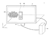
- FIG. 1 is a schematic diagram illustrating an example of a display control system according to an embodiment
- FIG. 2 is a diagram illustrating positional relations between a transparent display and a viewpoint and between the transparent display and an object
- FIG. 3 is a block diagram illustrating an example of a logical configuration of a display control apparatus according to an embodiment
- FIG. 4 is a diagram illustrating a method of specifying the direction of the viewpoint on an xz plane (horizontal plane);
- FIG. 5 is a diagram illustrating a method of specifying the position of the viewpoint on the xz plane (horizontal plane);
- FIG. 6 is a diagram illustrating a method of specifying the direction of the viewpoint on a yz plane
- FIG. 7 is a diagram illustrating a first example of an interference region
- FIG. 8 is a diagram illustrating a second example of the interference region
- FIG. 9 is a diagram illustrating a third example of the interference region.
- FIG. 10 is a diagram illustrating a fourth example of the interference region
- FIG. 11 is a diagram illustrating an example of a display object in the screen including the interference region
- FIG. 12 is a diagram illustrating another example of the display object in the screen including the interference region
- FIG. 13 is a diagram illustrating an example of the display object moving in the screen including the interference region
- FIG. 14 is a diagram illustrating an interference region according to a modified example
- FIG. 15 is a diagram illustrating an example of the display object of which a display position is changed.
- FIG. 16 is a diagram illustrating an example of the display object of which a display attribute is changed
- FIG. 17 is a diagram illustrating an example of the display position of the display object for a stereoscopic view
- FIG. 18 is a diagram illustrating an example of the display object displayed to be stereoscopically viewed
- FIG. 19 is a diagram illustrating another example of the display object displayed to be stereoscopically viewed.
- FIG. 20 is a diagram illustrating a first example of a collision prevention object
- FIG. 21 is a diagram illustrating a timing example of display of the collision prevention object
- FIG. 22 is a diagram illustrating a second example of the collision prevention object
- FIG. 23 is a diagram illustrating a timing example of display of a collision prevention object in accordance with the position of an object
- FIG. 24 is a block diagram illustrating an example of a hardware configuration of the display control apparatus according to an embodiment
- FIG. 25 is a flowchart illustrating a first example of a schematic processing flow of a display control process according to an embodiment
- FIG. 26 is a flowchart illustrating a second example of the schematic processing flow of the display control process according to an embodiment.
- FIG. 27 is a flowchart illustrating a third example of the schematic processing flow of the display control process according to an embodiment
- FIG. 1 is a schematic diagram illustrating an example of a display control system 1 according to this embodiment.
- the display control system 1 includes a transparent display 10 , a camera 20 , and a display control apparatus 100 .
- x, y, and z axes representing three perpendicular axes in a three-dimensional space are illustrated. More specifically, the x axis represents an axis parallel to a horizontal direction of a screen 200 of the transparent display 10 .
- the y axis represents an axis parallel to the vertical direction of the screen 200 of the transparent display 10 .
- the z axis represents an axis perpendicular to the screen 200 (xy plane) of the transparent display 10 .
- the transparent display 10 is a display apparatus that includes the screen 200 configured to transmit light arriving from an object 90 located on the side of a second surface so that the object 90 can be viewed from a viewpoint position set on the side of a first surface which is the opposite surface to the second surface.
- the transparent display 10 can display a generated display image on the screen 200 .
- the display image to be displayed includes a display object 230 such as a menu, a figure, text, an icon, or a window.
- the transparent display 10 can be realized using, for example, polymer-scattered liquid crystal (polymer-dispersed liquid crystal or polymer network liquid crystal).
- the transparent display 10 may be realized using other liquid crystal, an organic electro-luminescence display, or the like.
- the transparent display 10 may be a touch panel apparatus that includes a touch detection surface.
- a display position of the display object 230 displayed on the screen 200 of the transparent display 10 may be changed in response to a touch on the screen 200 .
- a resistive film method, an electrostatic capacitance method, an optical method, an electromagnetic induction method, an ultrasonic wave method, or the like may be applied as the method of detecting a touch.
- the embodiment of the present disclosure is not limited thereto, but any method of detecting a touch can be used:
- the transparent display 10 may be a display apparatus that displays the display object 230 on the screen 200 so as to be stereoscopically viewable. More specifically, the transparent display 10 displays right-eye and left-eye images on the screen 200 .
- the right-eye image includes a right-eye object of the display object 230 .
- the left-eye image includes a left-eye object of the display object 230 .
- An offset in right and left directions (that is, the x-axis direction) is present between the display positions of the right-eye and left-eye objects within the screen 200 .
- the offset causes a deviation (that is, a parallax between the eyes) in the relative position of the display object 230 to occur between the right and left retinas of a person who views the screen 200 .
- Motion that is, convergence
- a naked-eye type method such as a lenticular method or a parallax barrier method is used as a method for stereoscopic view.
- a simple configuration in which the screen 200 is covered with a slit or a lenticular lens is used.
- the lenticular method and the parallax barrier method are also applicable to the transparent display 10 .
- another naked-eye stereoscopic method may be applied or a glasses-type method such as a polarized filter method or a liquid crystal shutter method may be applied.
- an arbitrary method of realizing stereoscopic view display in the transparent display 10 is applied.
- FIG. 2 is a diagram illustrating a positional relation among the transparent display 10 , a viewpoint 80 , and the object 90 .
- the viewpoint 80 is located on the side of the first surface (that is, a direction A in FIG. 2 ) of the transparent display 10 and the object 90 is located on the side of the second surface (that is, a direction B in FIG. 2 ) of the transparent display 10 .
- the display of the transparent display 10 is controlled based on a positional relation among the three.
- the viewpoint means both eyes of a person.
- the viewpoint may mean a camera (or a lens of a camera). That is, the viewpoint refers to any agent that perceives or recognizes the object 90 and the display object 230 .
- the object 90 may be a stationary object. Further, the object 90 may be operated or may be an independently moving object such as a person, an animal, or a machine.
- the camera 20 images a person located on the side of the first surface (that is, the direction A in FIG. 2 ) of the transparent display 10 .
- the camera 20 is provided, for example, at the central position of the transparent display 10 on the xz plane (that is, the horizontal plane) shown in FIG. 1 .
- the camera 20 has, for example, a horizontal image angle 2 ⁇ and a vertical image angle 2 ⁇ .
- the horizontal and vertical image angles are used to recognize the direction of the viewpoint 80 .
- the camera 20 outputs a digital image obtained through imaging to the display control apparatus 100 .
- the viewpoint means an agent (for example, a camera) other than the eyes of a person, the camera 20 may image this agent.
- the display control apparatus 100 controls the display of the transparent display 10 .
- the display control apparatus 100 acquires position information indicating a relative positional relation between the transparent display 10 and the viewpoint 80 or the object 90 , and then controls the display of the transparent display 10 based on the position information.
- position information indicating a relative positional relation between the transparent display 10 and the viewpoint 80 or the object 90
- controls the display of the transparent display 10 based on the position information thus, it is possible to realize the display of the transparent display suitable for viewing an object through the transparent display from a viewpoint.
- the display control apparatus 100 will be described in detail in “2. Configuration of Display Control Apparatus.”
- the display control system 1 may further include other elements in addition to the transparent display 10 , the camera 20 , and the display control apparatus 100 .
- the display control system 1 may include not only the camera 20 but also an additional camera that images an object 90 .
- the additional camera may be a camera that can measure the distance of an object.
- a camera such as a stereo camera or a camera capable of measuring the distance of an object, such as a time-of-flight (TOF) range image sensor, is used as the additional camera. Even when the position of the object 90 is moved, the position of the object 90 can be recognized by the additional camera.
- the camera 20 may also be a camera capable of measuring the distance.
- the display control system 1 may further include a separate apparatus that supplies information to recognize the position of the viewpoint 80 or the object 90 instead of the camera 20 or the above-described additional camera.
- the separate apparatus may be an infrared sensor or a pressure sensor provided on the side of the first surface (that is, the direction A in FIG. 2 ) or the side of the second surface (the direction B in FIG. 2 ) of the transparent display 10 .
- the separate apparatus May be a reception apparatus that receives radio waves from a transmitter disposed in the vicinity of the view point 80 or the object 90 and generates information used to specify the position of the viewpoint 80 or the object 90 based on the received radio waves.
- the display control system 1 may include any apparatus that supplies information used to specify the position or the distance of the viewpoint 80 or the object 90 .
- the display control system 1 may include an apparatus that recognizes the position of the viewpoint 80 or the object 90 based on a digital image from the camera 20 or information from another apparatus. In this case, the display control apparatus 100 may not have a function of recognizing the position of the viewpoint 80 or the object 90 .
- the display control system 1 may include an apparatus that generates a display image to be displayed on the transparent display 10 under the control of the display control apparatus 100 . In this case, the display control apparatus 100 may not have a function of generating the display image.
- the display control system 1 may further include an input apparatus that operates the display object 230 displayed on the transparent display 10 .
- the input apparatus include a mouse, a keyboard, a touch panel, a button, a switch, a lever, a remote controller, and an external connection apparatus, such as a cellular phone or a PDA, corresponding to an operation of the transparent display 10 .
- FIG. 3 is a block diagram illustrating an example of the logical configuration of the display control apparatus 100 according to this embodiment.
- the display control apparatus 100 includes a recognition unit 110 , an acquisition unit 120 , a storage unit 130 , an image generation unit 140 , and a display control unit 150 .
- the recognition unit 110 recognizes the relative position of the viewpoint 80 with respect to the transparent display 10 or the object 90 .
- the position of the viewpoint 80 is the position of both eyes of the person located on the side of the first surface of the transparent display 10 .
- the recognition unit 110 recognizes the relative position of the viewpoint 80 with respect the transparent display 10 or the object 90 from a digital image acquired from the camera 20 .
- the recognition unit 110 recognizes the relative position of the viewpoint 80 with respect to the transparent display 10 or the object 90 by recognizing the relative position of the face of the person.
- a method of recognizing the position of the viewpoint 80 by recognizing the position of the face of the person will be described. Accordingly, in the recognition of the position, the viewpoint 80 is substantially identical with the face of the person.
- the recognition unit 110 recognizes the relative position of the viewpoint 80 with respect to the transparent display 10 by specifying the direction and the distance of the viewpoint 80 from the center of the transparent display 10 on the xz plane (that is, the horizontal surface) shown in FIG. 1 .
- FIG. 4 is a diagram illustrating the method of specifying the direction of the viewpoint 80 on the xz plane (horizontal plane).
- the camera 20 has a horizontal image angle of 2 ⁇ .
- the viewpoint 80 is located at an angle deviated by ⁇ 1 to the left from the center of the horizontal image angle of the camera 20 .
- the camera 20 is provided at the same position as the center of the transparent display 10 on the xz plane.
- the viewpoint 80 is located at an angle deviated only ⁇ 1 from the straight line which is parallel to the z axis and passes through the center of the transparent display 10 . Accordingly, the direction of the viewpoint 80 from the center of the transparent display 10 on the xz plane is expressed by the angle ⁇ 1 . Further, the angle ⁇ 1 may be expressed as a positive value when the viewpoint 80 is deviated to the left, and expressed as a negative value when the viewpoint 80 is deviated to the right, or vice versa.
- a digital image 22 imaged by the camera 20 is shown.
- the recognition unit 110 detects the face in the digital image 22 and obtains a distance d 1 of the face (that is, the viewpoint 80 ) from the center of the digital image 22 .
- the distance d 1 is a positive number less than 0.5. In this case, the following expression is satisfied.
- the recognition unit 110 can obtain the angle ⁇ 1 using the distance d 1 and the given horizontal image angle ⁇ .
- the recognition unit 110 can specify the direction ⁇ 1 of the viewpoint 80 from the center of the transparent display 10 on the xz plane.
- the recognition unit 110 can obtain the distance D 1 of the viewpoint 80 from the camera 20 in the z-axis direction from the size of the face of the person detected from the digital image 22 .
- information for example, a lookup table
- the recognition unit 110 obtains the distance matching the size from the detected size of the face of the person.
- the distance D 1 of the viewpoint 80 from the camera 20 may be used to obtain the distance D 1 of the viewpoint 80 from the camera 20 .
- the camera 20 is provided at the same position as the center of the transparent display 10 on the xz plane, as shown in FIG. 1 .
- the distance of the viewpoint 80 from the center of the transparent display 10 is set to the distance D 1 , which is the same as the distance of the viewpoint 80 from the camera 20 , in the z-axis direction. Accordingly, the distance of the viewpoint 80 from the center of the transparent display 10 in the z-axis direction is expressed by the distance D 1 .
- the recognition unit 110 may specify the distance D 1 of the viewpoint 80 from the center of the transparent display 10 in the z-axis direction. Further, when the center of the transparent display 10 is not the same as the position of the camera 20 on the xz plane, but the offset distance between the transparent display 10 and the position of the camera 20 is given, the distance between the transparent display 10 and the viewpoint 80 may be specified by performing correction by the offset distance.
- the recognition unit 110 recognizes the relative position of the viewpoint 80 with respect to the transparent display 10 on the xz plane by specifying the direction ⁇ 1 and the distance D 1 of the viewpoint 80 from the center of the transparent display 10 .
- the relative position of the viewpoint 80 with respect to the transparent display 10 on the xz plane has been described with reference to FIGS. 4 and 5 .
- the relative position of the viewpoint 80 with respect to the transparent display 10 may be recognized even on the yz plane.
- a vertical image angle 2 ⁇ may be used instead of the horizontal image angle 2 ⁇ and a distance d 2 in the digital image 22 may be obtained instead of the distance d 1 in the digital image 22 .
- a direction 82 of the viewpoint 80 with respect to the camera 20 can be obtained by the above-described method.
- the distance D 1 (that is, the distance in the z-axis direction) of the viewpoint 80 from the center of the camera 20 (or the transparent display 10 ) is likewise used even on the yz plane.
- the position of the camera 20 and the position of the center of the transparent display 10 are different from each other by an offset distance D offset in the y-axis direction. Accordingly, a position corrected in the y-axis direction by the offset distance D offset , which is obtained from the direction 82 and the distance D 1 , from the relative position of the viewpoint 80 with respect to the camera 20 becomes the relative position of the viewpoint 80 with respect to the transparent display 10 on the yz plane.
- the relative position of the viewpoint 80 with respect to the transparent display 10 has been described above, but the relative position of the viewpoint 80 with respect to the object 90 may be recognized. Further, although the recognition of the relative position of the viewpoint 80 with respect to the transparent display 10 based on the digital image has been described, the embodiment of the present disclosure is not limited thereto.
- the relative position of the viewpoint 80 with respect to the transparent display 10 may be recognized based on information obtained from another apparatus, such as an infrared sensor, a pressure sensor, or a reception apparatus other than the camera, that receives radio waves from a transmitter included in the object 90 or disposed in the vicinity of the viewpoint 80 .
- the recognition unit 110 may recognize the relative position of the object 90 with respect to the transparent display 10 or the viewpoint 80 .
- the recognition unit 110 may recognize the relative position of the object 90 with respect to the transparent display 10 or the viewpoint 80 from a digital image obtained from an additional camera different from the camera 20 or information obtained from another apparatus such as an infrared sensor or a pressure sensor.
- the recognition unit 110 may also recognize the size of the object 90 .
- the recognition unit 110 may recognize a distance (hereinafter referred to as a “touch distance”) between the transparent display 10 and a person or a part (for example, a hand) of the body of the person located on the side of the first surface of the transparent display from the digital image obtained from the camera 20 or the information obtained from another apparatus such as an infrared sensor or a pressure sensor.
- a distance hereinafter referred to as a “touch distance”
- the acquisition unit 120 acquires position information indicating the relative positional relations between the transparent display 10 and the viewpoint 80 located on the side of the first surface (that is, the direction A in FIG. 2 ) of the transparent display 10 and between the transparent display 10 and the object 90 located on the side of the second surface (that is, the direction B in FIG. 2 ) of the transparent display 10 .
- the position information is arbitrary information indicating the relative positional relations between the transparent display 10 and the viewpoint 80 and between the transparent display 10 and the object 90 .
- the position information is information indicating the relative position of the viewpoint 80 with respect to the transparent display 10 and the relative position of the object 90 with respect to the transparent display 10 . In this case, for example, as shown in FIG.
- the relative position of the viewpoint 80 with respect to the transparent display 10 is expressed by the direction ⁇ 1 and the distance D 1 of the viewpoint 80 from the center of the transparent display 10 .
- the position information may be information indicating the relative position of the viewpoint 80 with respect to the object 90 and the relative position of the object 90 with respect to the transparent display 10 .
- the position information may be information including the positions of the transparent display 10 , the viewpoint 80 , and the object 90 with respect to the origin set at one position.
- the positions of the transparent display 10 , the viewpoint 80 , and the object 90 are not limited to the central points, but may be any point among the central points or any point in the vicinity of the central points. Any point may include two or more points or may be in the range including two or more points.
- the position information may be information including the size of the object 90 .
- the position information may include not only the relative positional relation on the xz plane (that is, the horizontal surface) but also the relative position information on the yz plane.
- the acquisition unit 120 acquires the relative position of the viewpoint 80 with respect to the transparent display 10 or the object 90 from the recognition unit 110 . Further, for example, the acquisition unit 120 acquires the relative position of the object 90 with respect to the transparent display 10 from the storage unit 130 . When the recognition unit 110 recognizes the relative position of the object 90 with respect to the transparent display 10 , the acquisition unit 120 may acquire the relative position of the object 90 with respect to the transparent display 10 from the recognition unit 110 . The acquisition unit 120 may additionally acquire the size of the object 90 .
- the acquisition unit 120 may additionally acquire a touch distance as a first distance between the transparent display 10 and a person located on the side of the first surface of the transparent display 10 or a part of the body of the person. For example, the acquisition unit 120 may acquire the touch distance from the recognition unit 110 .
- the storage unit 130 stores information temporarily or permanently stored for the display control apparatus 100 .
- the storage unit 130 stores the relative position of the object 90 with respect to the transparent display 10 .
- the relative position of the object 90 with respect to the transparent display 10 is set by an administrator of the display control apparatus 100 and is stored in the storage unit 130 .
- the relative position of the object 90 with respect to the transparent display 10 may be recognized by the recognition unit 110 and may be stored in the storage unit 130 .
- the recognition unit 110 may reduce the frequency of the recognition on the assumption that the object 90 does not frequently move.
- the storage unit 130 may additionally store the size of the object 90 .
- the size of the object 90 may be set by the administrator of the display control apparatus 100 or may be recognized by the recognition unit 110 .
- the storage unit 130 stores information necessary for generating the display image to be displayed on the screen 200 of the transparent display 10 .
- the storage unit 130 stores the display position and the display attribute of the display object 230 necessary for displaying the display object 230 included in the display image.
- the display position and the display attribute of the display object 230 may be determined or modified in the display control of the display control unit 150 .
- the image generation unit 140 generates a display image to be displayed on the screen 200 of the transparent display 10 under the control of the display control unit 150 .
- the image generation unit 140 generates a display image, such as a menu, a figure, text, an icon, or a window, including the display object 230 .
- the image generation unit 140 outputs the display image to the transparent display 10 .
- the image generation unit 140 may generate right-eye and left-eye images.
- the display control unit 150 controls the display of the transparent display 10 .
- the display control unit 150 controls the display of the transparent display 10 particularly based on the position information indicating the relative position of the viewpoint 80 and the object 90 with respect to the transparent display 10 .
- An example of specific display control of the display control unit 150 will be described below in “2.2. Display Control Unit.”
- the display control unit 150 controls the display of the transparent display 10 so that the object 90 is viewable from the viewpoint 80 through the screen 200 of the transparent display 10 . More specifically, the display control unit 150 determines a region (hereinafter referred to as an “interference region”) in the screen 200 of the transparent display 10 based on the position information and controls the display of the transparent display 10 so that the object 90 is viewable from the viewpoint 80 through the interference region.
- an interference region a region in the screen 200 of the transparent display 10 based on the position information and controls the display of the transparent display 10 so that the object 90 is viewable from the viewpoint 80 through the interference region.
- the determined interference region includes an intersection point between the screen 200 of the transparent display 10 and a straight line passing through the position of the viewpoint 80 and the position of the object 90 in the position information or is present around the intersection point.
- FIGS. 7 to 10 are diagrams illustrating first to fourth examples of the interference region.
- the interference region 220 has a width W 1 centered at an intersection point 210 between the screen 200 of the transparent display and the straight line passing through the position of the viewpoint 80 and the position of the object 90 .
- the interference region 220 may not be centered at the intersection point 210 .
- the width W 1 may be changed in accordance with the size of the object 90 . Referring to FIG.
- the interference region 220 may have a width W 2 wider than the width W 1 .
- the width W 1 may be changed in accordance with the distance between the transparent display 10 and the viewpoint 80 or the distance between the transparent display 10 and the object 90 .
- the interference region 220 may have a width W 3 narrower than the width W 1 , when the distance between the transparent display 10 and the viewpoint 80 is smaller.
- the interference region 220 may have a width W 4 wider than the width W 1 , when the distance between the transparent display 10 and the object 90 is smaller. Referring to FIG.
- the interference region 220 may include two intersection points 210 a and 210 b between the screen 200 of the transparent display 10 and two straight lines passing through the position of the viewpoint 80 and two positions of the object 90 .
- the two positions of the object 90 are, for example, the positions of both ends of the object 90 in the x-axis direction.
- the interference region 220 has a width which is the sum of the width between the intersection points 210 a and 210 b and two widths W 5 on the sides.
- the interference region 220 may be a region excluding the intersection point 210 . That is, the interference region 220 may be present around the intersection point.
- the interference region By determining the interference region, a region supposed to be controlled so that the object 90 is viewable from the viewpoint 80 and a region allowed not to be controlled can be separated from each other clearly. As a result, the display of the display object 230 can be controlled at the region supposed to be controlled so that the view of the object 90 is not interrupted, while the display object 230 can be freely displayed at the region allowed not to be controlled. Further, by determining, as the interference region, the region including the intersection point between the screen 200 of the transparent display 10 and the straight line passing through the position of the viewpoint 80 and the position of the object 90 (or the region present in the vicinity of the intersection point), it is possible to obtain the interference region including a region at which the view of the object 90 from the viewpoint 80 is easily interrupted.
- the display control unit 150 controls the display of the transparent display 10 so that the object 90 can be viewed from the viewpoint 80 through the interference region 220 by various methods.
- the display control unit 150 may control the display of the transparent display 10 by causing the display object 230 to be not displayed within the determined interference region 220 .
- FIG. 11 is a diagram illustrating an example of the display object 230 in the screen 200 including the interference region 220 . Referring to FIG. 11 , a display object 230 a of text is displayed so as not to be included in the interference region 220 . Thus, the object 90 is not hidden by the display object 230 because the display object 230 is not displayed within the interference region 220 .
- the display control unit 150 may control the display of the transparent display 10 by setting the display attribute of the display object 230 within the determined interference region 220 as the display attribute in which the object 90 is viewable from the viewpoint 80 .
- the display attribute refers to any attribute, such as a transparency, a color, a display ON/OFF state, a size, a shape, an aspect ratio, or a rotation angle of the display object 230 , regarding the display of the display object 230 .
- FIG. 12 is a diagram illustrating another example of the display object 230 in the screen 200 including the interference region 220 . Referring to FIG.
- the display object 230 a of text is displayed in such a manner that the transparency is increased in the interference region 220 .
- the display object 230 a may be displayed with a considerably decreased size or with an unnoticeable color.
- the object 90 is scarcely hidden by the display object 230 . That is, even when the display object 230 is displayed on the screen 200 of the transparent display 10 , the object 90 remains easily viewable from the viewpoint 80 .
- the display control unit 150 may control the display of the transparent display 10 by not displaying the entire display screen (that is, switching the display to an OFF state) in the transparent display 10 .
- the display object 230 may be a display object of which a display position can be changed through an operation of a user.
- FIG. 13 is a diagram illustrating an example of the display object moving within the screen 200 including the interference region 220 .
- the display position of the display object 230 a of text can be changed in a direction C, in which the interference region 220 is present, through an operation such as a touch operation of a user.
- the display object 230 a is displayed not in the interference region 220 but in another region.
- the display object 230 a is displayed in such a manner that the transparency is increased in the interference region 220 .
- the object 90 remains easily viewable by the display object of which the display position can be changed by an operation of the user, and an operation is freely performed from the viewpoint 80 .
- the viewpoint 80 may include two or more viewpoints and the display control unit 150 may control the display of the transparent display 10 so that the object 90 can be viewed from at least one of the two or more viewpoints.
- FIG. 14 is a diagram illustrating the interference region 220 according to a modified example. As shown in 14 - 1 of FIG. 14 , for example, the display control unit 150 determines an interference region 220 a for a viewpoint 80 a and an interference region 220 b for a viewpoint 80 b . Then, the display control unit 150 controls the display of the transparent display 10 so that the object 90 can be viewed from the viewpoints 80 a and 80 b through the interference regions 220 a and 220 b , respectively. The object 90 remains easily viewable from two or more viewpoints by this control.
- the display control unit 150 may determine the interference region (that is, the interference region 220 a or 220 b ) for one of the viewpoints 80 a and 80 b .
- the object 90 remains easily viewable from at least one viewpoint by this control, and information indicated by the display object 230 can be delivered to the viewpoint.
- the interference region 220 with the width restricted in the horizontal direction (that is, the x-axis direction) of the screen 200 has hitherto been described.
- the display control unit 150 may determine the interference region 220 with a width restricted in a vertical direction (that is, the y-axis direction) of the screen 200 .
- the width in the vertical direction can be determined by the same method of the width in the horizontal direction.
- the interference region 220 may be a region with a width restricted in the horizontal direction and a width restricted in the vertical direction.
- the first example of the display control by the display control unit 150 has been described above. However, even when the display object 230 is displayed on the screen 200 of the transparent display 10 , the object 90 remains easily viewable from the viewpoint 80 by the display control.
- the display control unit 150 controls the display of the transparent display 10 by determining the display position or the display attribute of the display object 230 displayed on the screen 200 of the transparent display 10 based on the position information.
- the display control unit 150 changes the display position of the display object 230 in accordance with the change in the relative position of the viewpoint 80 with respect to the transparent display 10 or the relative position of the object 90 with respect to the transparent display 10 in the position information. More specifically, for example, the display control unit 150 changes the display position of the display object 230 in accordance with the change in the position of the intersection point between the screen 200 of the transparent display 10 and the straight line passing through the position of the viewpoint 80 and the position of the object 90 in the position information.
- FIG. 15 is a diagram illustrating an example of the display object of which a display position is changed. As shown in 15 - 1 and 15 - 2 of FIG.
- a display object 230 b indicating a price is displayed at a position a predetermined distance L away from the intersection point 210 .
- the position of the display object 230 b indicating the price of the object 90 is changed so as to maintain the position the predetermined distance L away from the intersection point 210 .
- the predetermined distance L may be a fixed distance or a distance changed in accordance with the position of the intersection point 210 .
- the display object 230 may be displayed at a position at which the display object 230 is desired to be viewed from the viewpoint 80 irrespective of the position of the viewpoint 80 .
- the display object 230 can follow the object 90 by changing the display position of the display object 230 in accordance with the change in the intersection point 210 . Accordingly, the display object 230 can be displayed in the vicinity of the object 90 irrespective of the position of the viewpoint 80 from which the object 90 is viewed.
- both the display object 230 and the object 90 can be easily viewed from the viewpoint 80 , and thus the relevance between the display object 230 and the object 90 can be understood more easily.
- the display control unit 150 changes the display attribute of the display object 230 in accordance with the change in the relative position of the viewpoint 80 with respect to the transparent display 10 or the relative position of the object 90 with respect to the transparent display 10 in the position information.
- the display attribute refers to any attribute, such as transparency, a color, a display ON/OFF state, a size, a shape, an aspect ratio, or a rotation angle of the display object 230 , regarding the display of the display object 230 .
- FIG. 16 is a diagram illustrating an example of a display object of which a display attribute is changed. As shown in 16 - 1 and 16 - 2 of FIG. 16 , a square display object 230 c with rounded corners is displayed so as to surround the object 90 .
- the display object with the display attribute desired to be viewed from the viewpoint 80 can be displayed by changing the display attribute of the display object 230 in accordance with the change in the position of the viewpoint 80 or the object 90 .
- the second example of the display control by the display control unit 150 has been described above.
- a more desirable display of the display object 230 can be realized by the display control no matter what position of the viewpoint 80 the object 90 is viewed from.
- the transparent display 10 displays the display object 230 so as to be stereoscopically displayed and the display control unit 150 determines the display position or the display attribute of the display object 230 for a stereoscopic view based on the position information.
- the display position of the display object 230 for the stereoscopic view is a position of the display object 230 perceived from the viewpoint 80 by the stereoscopic view in a three-dimensional space.
- the display position of the display object 230 for the stereoscopic view may be the coordinates (for example, coordinates (x, y)) of the screen 200 and the coordinates (for example coordinates (x, y, z)) including the depth (for example, z) in a direction perpendicular to the screen 200 from the screen 200 in a three-dimensional space.
- the image generation unit 140 may specify the display position of a left-eye object in the screen 200 (or a left-eye image) and the display position of a right-eye object in the screen 200 (or a right-eye image).
- the image generation unit 140 may directly generate the left-eye image including the left-eye object and the right-eye image including the right-eye object by performing rendering for the stereoscopic view based on the position of the display object in the three-dimensional space.
- the display position of the display object for the stereoscopic view may be the display position of the left-eye object in the screen 200 (or the left-eye image) and the display position of the right-eye object in the screen 200 (or the right-eye image).
- FIG. 17 is a diagram illustrating an example of the display position of the display object for the stereoscopic view.
- a left-eye object 230 e and a right-eye object 230 f for a left eye 82 and a right eye 84 , respectively, having an offset O are displayed on the screen 200 .
- the left eye 82 and the right eye 84 perceive a depth D 2 (that is, D 2 in the z axis direction) of a display object 230 d from the viewpoint 80 .
- the display position of the display object for the stereoscopic view is a position (for example, the coordinates (x, y, z)) of the display object 230 d perceived from the viewpoint 80 by the stereoscopic view in the three-dimensional space.
- the display position of the display object for the stereoscopic view may be the display position of the left-eye object 230 e in the screen 200 (or the left-eye image) and the display position of the right-eye object 230 f in the screen 200 (or the right-eye image).
- the display attribute for the stereoscopic view refers to any attribute, such as transparency, a color, a display ON/OFF state, a size, a shape, an aspect ratio, or a rotation angle of the display object 230 , regarding the display of the display object 230 .
- the shape may be a three-dimensional shape in a space.
- the rotation angle may be a three-dimensional rotation angle in a space.
- the display control unit 150 determines the display position of the display object for the stereoscopic view so that the display object 230 is displayed to be stereoscopically viewed at a depth in a direction (that is, the direction B in FIG. 2 or a positive direction of the z axis) from the side of the first surface to the side of the second surface of the transparent display 10 .
- FIG. 18 is a diagram illustrating an example of the display object 230 displayed to be stereoscopically viewed. Referring to FIG.
- the display control unit 150 determines the display position of a display object 230 g for a stereoscopic view so that the display object 230 g is displayed to be stereoscopically viewed at a depth in the direction B (that is, the positive direction of the z axis).
- the depth of the display object 230 perceived from the viewpoint 80 can be made to be closer than the actual depth from the screen 200 at the position occupied by the object 90 .
- the object 90 and the display object 230 can be viewed from the viewpoint 80 without considerable change in focus.
- since the object 90 and the display object 230 can be easily viewed together from the viewpoint 80 , it is possible to reduce the fatigue of the eyes of the viewpoint 80 .
- the display control unit 150 changes the display position or the display attribute of the display object 230 for the stereoscopic view in accordance with the change in the position of the viewpoint 80 or the position of the object 90 in the position information.
- the position of the viewpoint 80 is changed from the position of the viewpoint 80 in FIG. 18 .
- the display position and the display attribute (rotational angle) of the display object 230 d are changed so as to maintain the state in which the display object 230 d indicates the object 90 .
- the display object 230 with the position and the attribute desired to be viewed from the viewpoint 80 in the space can be displayed irrespective, of the position of the viewpoint 80 by changing the display position or the display attribute of the display object 230 for the stereoscopic view in accordance with the change in the position of the viewpoint 80 or the object 90 .
- the display object 230 can follow the object 90 in the three-dimensional space. Accordingly, the display object 230 can be displayed in the vicinity of the object 90 irrespective of the position of the viewpoint 80 from which the object 90 is viewed.
- both the display object 230 and the object 90 can be easily viewed from the viewpoint 80 , and thus the relevance between the display object 230 and the object 90 can be understood more easily.
- the display control unit 150 may cause a display object (hereinafter referred to as a “collision prevention object”) to be displayed to make a person located on the side of the first surface of the transparent display 10 aware of the presence of the transparent display 10 .
- FIG. 20 is a diagram illustrating a first example of the collision prevention object. Referring to FIG. 20 , for example, four circular stationary collision prevention objects 250 a are displayed on the display 200 of the transparent display 10 . Further, the display control unit 150 may cause the collision prevention object 250 to be displayed in accordance with a touch distance which is the distance between the transparent display 10 and the person or a part (for example, a hand) of the body of the person.
- FIG. 21 is a diagram illustrating a timing example of the display of the collision prevention object 250 .
- FIG. 22 is a diagram illustrating a second example of the display of the collision prevention object.
- a collision prevention object 250 b popping up dynamically so as to be perceived by the person may be displayed on the screen 200 of the transparent display 10 when the touch distance D 3 is less than the predetermined threshold value D t .
- the display of the collision prevention object 250 can prevent a situation in which the person-collides with the transparent display 10 without being aware of the presence of the transparent display 10 when attempting to touch the object 90 .
- the collision prevention object 250 by causing the collision prevention object 250 to be displayed in accordance with the touch distance, no collision prevention object can be displayed when there is no danger of collision. As a result, since the display object 230 can be displayed in a broader range, it is possible to ensure that the person easily views the object 90 from the viewpoint 80 .
- the display control unit 150 may cause the collision prevention object 250 to be displayed to the person even when the shorter the distance (hereinafter referred to as an “object disposition distance”) between the positions of the transparent display 10 and the object 90 in the position information is, the longer the touch distance is.
- FIG. 23 is a diagram illustrating a timing example of the display the collision prevention object 250 in accordance with the position of the object 90 .
- the predetermined threshold value D t of the touch distance D 3 is larger when an object disposition distance D 4 is smaller, as in 23 - 2 of FIG. 23 , than when the object disposition distance D 4 is larger, as in 23 - 1 of FIG. 23 .
- the display timing of the collision prevention object 250 is set in the above-described way to display the collision prevention object 250 earlier, and therefore the collision can be more likely to be prevented.
- the third example of the display control by the display control unit 150 has been described above.
- a more desirable stereoscopic display of the display object 230 can be realized by the display control no matter what position of the viewpoint 80 the object 90 is viewed from.
- FIG. 24 is a block diagram illustrating an example of the hardware configuration of the display control apparatus 100 according to the embodiment.
- the display control apparatus 100 includes a central processing unit (CPU) 181 , a read-only memory (ROM) 183 , a random access memory (RAM) 185 , a graphics processing unit (GPU) 187 , a bus 189 , a storage device 191 , and an input/output interface 193 .
- CPU central processing unit
- ROM read-only memory
- RAM random access memory
- GPU graphics processing unit
- the CPU 181 functions as an arithmetic processing device and a control device and controls all or some of the processes of the display control apparatus 100 in accordance with various programs stored in the ROM 183 , the RAM 185 , or the storage device 191 .
- the ROM 183 stores programs, calculation parameters, or the like used by the CPU 181 .
- the RAM 185 preliminarily stores the programs used by the CPU 181 or parameters or the like changed appropriately in execution of the programs.
- the GPU 187 performs various processes associated with the display of a display apparatus (for example, the transparent display 10 ) first from generation of a display screen.
- the bus 189 connects the CPU 181 , the ROM 183 , the RAM 185 , and the GPU 187 to each other. Further, the storage device 191 and the input/output interface 193 are connected to the bus 189 .
- the storage device 191 stores various kinds of data such as basic software such as an operation system (OS) or applications.
- examples of the storage device 191 include a magnetic recording medium such as a hard disk and a non-volatile memory such as an electrically erasable and programmable read-only memory (EEPROM), a flash memory, a magnetoresistive random access memory (MRAM), a ferroelectric random access memory (FeRAM), or a phase-change random access memory (PRAM), but the embodiment of the present disclosure is not limited to the mentioned examples.
- EEPROM electrically erasable and programmable read-only memory
- MRAM magnetoresistive random access memory
- FeRAM ferroelectric random access memory
- PRAM phase-change random access memory
- the input/output interface 193 connects the transparent display 10 , the camera 20 , and the like to each other.
- examples of the input/output interface 193 include a universal serial bus (USB) terminal, a digital visual interface (DVI) terminal, and a high-definition multimedia interface (HDMI) terminal, but the embodiment of the present disclosure is not limited to the mentioned examples.
- FIG. 25 is a flowchart illustrating a first example of a schematic processing flow of the display control process according to this embodiment.
- the display of the transparent display 10 is controlled by determining the display position or the display attribute of the display object 230 displayed on the screen 200 of the transparent display 10 based on the position information indicating the relative positional relations between the transparent display 10 and the viewpoint 80 and between the transparent display 10 and the object 90 .
- step S 310 the recognition unit 110 first recognizes the relative position of the viewpoint 80 with respect to the transparent display 10 or the object 90 .
- step S 320 the acquisition unit 120 acquires the position information indicating the relative positional relations between the transparent display 10 and the viewpoint 80 and between the transparent display 10 and the object 90 .
- step S 330 based on the position information, the display control unit 150 determines the display position or the display attribute of the display object 230 to be displayed on the screen 200 of the transparent display 10 .
- step S 340 based on the determined display position or the determined display attribute, the image generation unit 140 generates the display image including the display object 230 to be displayed on the screen 200 of the transparent display 10 .
- FIG. 26 is a flowchart illustrating a second example of the schematic processing flow of the display control process according to this embodiment.
- the display position of the display object 230 is determined so that the object 90 can be viewed from the viewpoint 80 through the screen 200 of the transparent display 10 in step S 330 of the first example of the display control process.
- step S 332 , step S 334 , and step S 336 of the second example of the display control process which are different from those of the first example of the display control process shown in FIG. 25 , will be described.
- step S 332 the display control unit 150 determines the interference region 220 based on the position information indicating the relative positional relations between the transparent display 10 and the viewpoint 80 and between the transparent display 10 and the object 90 .
- step S 334 the display control unit 150 determines whether a display object overlapping the interference region 220 is present in the display object 230 included in the display image.
- the process proceeds to step S 336 .
- the process proceeds to step S 340 .
- step S 336 the display control unit 150 changes the display position of the display object 230 overlapping the interference region 220 so that the display object 230 does not overlap the interference region 220 .
- FIG. 27 is a flowchart illustrating a third example of the schematic processing flow of the display control process according to this embodiment.
- the display position of the display object 230 is changed in accordance with the change in the position of the viewpoint 80 or the object 90 in step S 330 of the first example of the display control process.
- step S 338 and step S 339 of the third example of the display control process which are different from those of the first example of the display control process shown in FIG. 25 , will be described.
- step S 338 the display control unit 150 specifies the intersection point between the screen 200 of the transparent display 10 and the straight line passing through the position of the viewpoint 80 and the position of the object 90 in the position information.
- step S 339 the display control unit 150 determines the position of the display object 230 in accordance with the position of the intersection point.
- the display control system 1 and the display control apparatus 100 according the embodiment of the present disclosure have been described above with reference to FIGS. 1 to 27 .
- the display of the transparent display 10 can be realized so as to be suitable for viewing the object 90 from the viewpoint 80 through the transparent display 10 .
- the display of the transparent display 10 is controlled so that the object 90 can be viewed from the viewpoint 80 through the screen 200 of the transparent display 10 .
- the object 90 remains easily viewable from the viewpoint 80 .
- the display of the transparent display 10 is controlled by determining the display position or the display attribute of the display object 230 to be displayed on the screen 200 of the transparent display 10 based on the position information.
- the more desirable display of the display object 230 can be realized.
- the display of the transparent display 10 is controlled by determining the display position or the display attribute of the display object 230 for the stereoscopic view based on the position information.
- the more desirable display of the display object 230 can be realized.
- the display control apparatus including the recognition unit and the image generation unit has been described, but the present disclosure is not limited thereto.
- the display control apparatus may not include the recognition unit and the image generation unit and another apparatus directly or indirectly connected to the display control apparatus may include the recognition unit and the image generation unit.
- present technology may also be configured as below.
- a display control apparatus controlling display of a transparent display which includes a screen configured to transmit light arriving from an object located on a side of a second surface so that the object is viewable from a viewpoint located on a side of a first surface which is an opposite surface to the second surface, the apparatus comprising:
- an acquisition unit that acquires position information indicating relative positional relations between the transparent display and the viewpoint and between the transparent display and the object
- a display control unit that controls the display of the transparent display based on the position information.
- the viewpoint includes two or more viewpoints
- the display control unit controls the display of the transparent display so that the object is viewable from at least one of the two or more viewpoints.
- the transparent display displays the display object so as to be stereoscopically viewable
- the display control unit determines the display position or the display attribute of the display object for a stereoscopic view based on the position information.
- the acquisition unit additionally acquires a first distance between the transparent display and the person or a part of a body of the person, and
- the display control unit causes the display object to be displayed to make the person aware of the presence of the transparent display in accordance with the first distance.
- the viewpoint is eyes of a person located on the side of the first surface of the transparent display
- the display control apparatus recognizes a relative position of the viewpoint with respect to the transparent display or the object by recognizing a relative position of a face of the person with respect to the transparent display or the object.
- a display control method of controlling display of a transparent display which includes a screen configured to transmit light arriving from an object located on a side of a second surface so that the object is viewable from a viewpoint located on a side of a first surface which is an opposite surface to the second surface, the display control method comprising:
Landscapes
- Engineering & Computer Science (AREA)
- Theoretical Computer Science (AREA)
- Physics & Mathematics (AREA)
- General Physics & Mathematics (AREA)
- General Engineering & Computer Science (AREA)
- Human Computer Interaction (AREA)
- Computer Hardware Design (AREA)
- Multimedia (AREA)
- Chemical & Material Sciences (AREA)
- Crystallography & Structural Chemistry (AREA)
- Controls And Circuits For Display Device (AREA)
- User Interface Of Digital Computer (AREA)
- Digital Computer Display Output (AREA)
- Liquid Crystal Display Device Control (AREA)
- Transforming Electric Information Into Light Information (AREA)
- Control Of Indicators Other Than Cathode Ray Tubes (AREA)
Abstract
A display control apparatus controls display of a transparent display which includes a screen configured to transmit light arriving from an object located on a side of a second surface so that the object is viewable from a viewpoint located on a side of a first surface which is an opposite surface to the second surface. The display control apparatus includes: an acquisition unit that acquires position information indicating relative positional relations between the transparent display and the viewpoint and between the transparent display and the object; and a display control unit that controls the display of the transparent display based on the position information.
Description
The present application is a continuation application of U.S. patent application Ser. No. 13/537,175, filed Jun. 29, 2012, which claims priority from Japanese Patent Application No. JP 2011-150485 filed in the Japanese Patent Office on Jul. 6, 2011, the entire content of which is incorporated herein by reference.
The present disclosure relates to a display control apparatus, a display control method, and a computer program.
In recent years, transparent displays that include a screen transmitting light from one surface side to the other surface side have been realized and developed. The transparent displays are realized by liquid crystal such as polymer-dispersed liquid crystal. The liquid crystal diffuses light when an application voltage is in an off-state, and transmits light when the application voltage is in an on-state.
Japanese Unexamined Patent Application Publication No. 2010-183378 discloses a technology of changing the direction of characters or signs displayed on the screen of a transparent display depending on a surface of a transparent display viewed by a user in a portable telephone including the transparent display.
In the technology disclosed in Japanese Unexamined Patent Application Publication No. 2010-183378, when a user views an object through a transparent display from a given viewpoint, characters or signs on the screen of the transparent display may not be displayed in a suitable state for the user. For example, the characters or the signs displayed on the screen of the transparent display may hinder the user from viewing the object.
It is desirable to provide a novel and improved display control apparatus, a novel and improved display control method, and a novel and improved computer program suitable for viewing an object from a viewpoint through a transparent display.
According to an embodiment of the present disclosure, there is provided a display control apparatus controlling display of a transparent display which includes a screen configured to transmit light arriving from an object located on a side of a second surface so that the object is viewable from a viewpoint located on a side of a first surface which is an opposite surface to the second surface. The display control apparatus includes: an acquisition unit that acquires position information indicating relative positional relations between the transparent display and the viewpoint and between the transparent display and the object; and a display control unit that controls the display of the transparent display based on the position information.
According to another embodiment of the present disclosure, there is provided a display control method of controlling display of a transparent display which includes a screen configured to transmit light arriving from an object located on a side of a second surface so that the object is viewable from a viewpoint located on a side of a first surface which is an opposite surface to the second surface. The display control method includes: acquiring position information indicating relative positional relations between the transparent display and the viewpoint and between the transparent display and the object; and controlling the display of the transparent display based on the position information.
According to still another embodiment of the present disclosure, there is provided a computer program causing a computer, which is directly or indirectly connected to a transparent display which includes a screen configured to transmit light arriving from an object located on a side of a second surface so that the object is viewable from a viewpoint located on a side of a first surface which is an opposite surface to the second surface, to execute: acquiring position information indicating relative positional relations between the transparent display and the viewpoint and between the transparent display and the object; and controlling the display of the transparent display based on the position information. Here, the computer program may be supplied using a computer readable recording medium or may be supplied via a communication unit or the like.
According to the embodiments of the present disclosure described above, it is possible to realize the display of the transparent display suitable for viewing an object from a viewpoint through the transparent display.
Hereinafter, preferred embodiments of the present disclosure will be described in detail with reference to the appended drawings. Note that, in this specification and the appended drawings, structural elements that have substantially the same function and structure are denoted with the same reference numerals, and repeated explanation of these structural elements is omitted.
The description will be made in the following order.
1. Overview of Display Control System
2. Configuration of Display Control Apparatus
-
- 2.1. Logical Configuration of Display Control Apparatus
- 2.2. Display Control Unit
- 2.3. Hardware Configuration of Display Control Apparatus
3. Processing Flow
4. Summarization
1. Overview of Display Control System
First, the overall configuration of a display control system according to an embodiment of the present disclosure will be described with reference to FIG. 1 . FIG. 1 is a schematic diagram illustrating an example of a display control system 1 according to this embodiment. The display control system 1 according to this embodiment includes a transparent display 10, a camera 20, and a display control apparatus 100. In FIG. 1 and other drawings, x, y, and z axes representing three perpendicular axes in a three-dimensional space are illustrated. More specifically, the x axis represents an axis parallel to a horizontal direction of a screen 200 of the transparent display 10. The y axis represents an axis parallel to the vertical direction of the screen 200 of the transparent display 10. The z axis represents an axis perpendicular to the screen 200 (xy plane) of the transparent display 10.
The transparent display 10 is a display apparatus that includes the screen 200 configured to transmit light arriving from an object 90 located on the side of a second surface so that the object 90 can be viewed from a viewpoint position set on the side of a first surface which is the opposite surface to the second surface. The transparent display 10 can display a generated display image on the screen 200. The display image to be displayed includes a display object 230 such as a menu, a figure, text, an icon, or a window. The transparent display 10 can be realized using, for example, polymer-scattered liquid crystal (polymer-dispersed liquid crystal or polymer network liquid crystal). The transparent display 10 may be realized using other liquid crystal, an organic electro-luminescence display, or the like.
The transparent display 10 may be a touch panel apparatus that includes a touch detection surface. In this case, a display position of the display object 230 displayed on the screen 200 of the transparent display 10 may be changed in response to a touch on the screen 200. Further, a resistive film method, an electrostatic capacitance method, an optical method, an electromagnetic induction method, an ultrasonic wave method, or the like may be applied as the method of detecting a touch. However, the embodiment of the present disclosure is not limited thereto, but any method of detecting a touch can be used:
The transparent display 10 may be a display apparatus that displays the display object 230 on the screen 200 so as to be stereoscopically viewable. More specifically, the transparent display 10 displays right-eye and left-eye images on the screen 200. The right-eye image includes a right-eye object of the display object 230. The left-eye image includes a left-eye object of the display object 230. An offset in right and left directions (that is, the x-axis direction) is present between the display positions of the right-eye and left-eye objects within the screen 200. The offset causes a deviation (that is, a parallax between the eyes) in the relative position of the display object 230 to occur between the right and left retinas of a person who views the screen 200. The person perceives the depth of the display object 230 from the screen 200 due to the parallax between the eyes. Motion (that is, convergence) is caused in the right and left eyes, whose lines of sight of the display object 230 displayed to be stereoscopically viewed by the offset intersect. The person perceives the depth of the display object 230 also by muscle control of the motions of the eyes. A naked-eye type method such as a lenticular method or a parallax barrier method is used as a method for stereoscopic view. In the lenticular method and the parallax barrier method, a simple configuration in which the screen 200 is covered with a slit or a lenticular lens is used. Accordingly, the lenticular method and the parallax barrier method are also applicable to the transparent display 10. Further, another naked-eye stereoscopic method may be applied or a glasses-type method such as a polarized filter method or a liquid crystal shutter method may be applied. In this embodiment, an arbitrary method of realizing stereoscopic view display in the transparent display 10 is applied.
The camera 20 images a person located on the side of the first surface (that is, the direction A in FIG. 2 ) of the transparent display 10. As shown in FIG. 1 , the camera 20 is provided, for example, at the central position of the transparent display 10 on the xz plane (that is, the horizontal plane) shown in FIG. 1 . As will be described later, the camera 20 has, for example, a horizontal image angle 2α and a vertical image angle 2β. The horizontal and vertical image angles are used to recognize the direction of the viewpoint 80. The camera 20 outputs a digital image obtained through imaging to the display control apparatus 100. Further, when the viewpoint means an agent (for example, a camera) other than the eyes of a person, the camera 20 may image this agent.
The display control apparatus 100 controls the display of the transparent display 10. In this embodiment, the display control apparatus 100 acquires position information indicating a relative positional relation between the transparent display 10 and the viewpoint 80 or the object 90, and then controls the display of the transparent display 10 based on the position information. Thus, it is possible to realize the display of the transparent display suitable for viewing an object through the transparent display from a viewpoint. The display control apparatus 100 will be described in detail in “2. Configuration of Display Control Apparatus.”
Other Configuration
The display control system 1 may further include other elements in addition to the transparent display 10, the camera 20, and the display control apparatus 100. For example, the display control system 1 may include not only the camera 20 but also an additional camera that images an object 90. Further, the additional camera may be a camera that can measure the distance of an object. To measure the distance of the object 90, a camera such as a stereo camera or a camera capable of measuring the distance of an object, such as a time-of-flight (TOF) range image sensor, is used as the additional camera. Even when the position of the object 90 is moved, the position of the object 90 can be recognized by the additional camera. Further, the camera 20 may also be a camera capable of measuring the distance.
The display control system 1 may further include a separate apparatus that supplies information to recognize the position of the viewpoint 80 or the object 90 instead of the camera 20 or the above-described additional camera. The separate apparatus may be an infrared sensor or a pressure sensor provided on the side of the first surface (that is, the direction A in FIG. 2 ) or the side of the second surface (the direction B in FIG. 2 ) of the transparent display 10. The separate apparatus May be a reception apparatus that receives radio waves from a transmitter disposed in the vicinity of the view point 80 or the object 90 and generates information used to specify the position of the viewpoint 80 or the object 90 based on the received radio waves. The display control system 1 according to this embodiment may include any apparatus that supplies information used to specify the position or the distance of the viewpoint 80 or the object 90.
The display control system 1 may include an apparatus that recognizes the position of the viewpoint 80 or the object 90 based on a digital image from the camera 20 or information from another apparatus. In this case, the display control apparatus 100 may not have a function of recognizing the position of the viewpoint 80 or the object 90. The display control system 1 may include an apparatus that generates a display image to be displayed on the transparent display 10 under the control of the display control apparatus 100. In this case, the display control apparatus 100 may not have a function of generating the display image.
The display control system 1 may further include an input apparatus that operates the display object 230 displayed on the transparent display 10. Examples of the input apparatus include a mouse, a keyboard, a touch panel, a button, a switch, a lever, a remote controller, and an external connection apparatus, such as a cellular phone or a PDA, corresponding to an operation of the transparent display 10.
2. Configuration of Display Control Apparatus
Next, the configuration of the display control apparatus 100 according to this embodiment will be described with reference to FIGS. 3 to 24 .
2.1. Logical Configuration of Display Control Apparatus
First, an example of the logical configuration of the display control apparatus 100 according to this embodiment will be described with reference to FIGS. 3 to 6 . FIG. 3 is a block diagram illustrating an example of the logical configuration of the display control apparatus 100 according to this embodiment. Referring to FIG. 3 , the display control apparatus 100 includes a recognition unit 110, an acquisition unit 120, a storage unit 130, an image generation unit 140, and a display control unit 150.
The recognition unit 110 recognizes the relative position of the viewpoint 80 with respect to the transparent display 10 or the object 90. For example, the position of the viewpoint 80 is the position of both eyes of the person located on the side of the first surface of the transparent display 10. For example, the recognition unit 110 recognizes the relative position of the viewpoint 80 with respect the transparent display 10 or the object 90 from a digital image acquired from the camera 20. For example, the recognition unit 110 recognizes the relative position of the viewpoint 80 with respect to the transparent display 10 or the object 90 by recognizing the relative position of the face of the person. Here, a method of recognizing the position of the viewpoint 80 by recognizing the position of the face of the person will be described. Accordingly, in the recognition of the position, the viewpoint 80 is substantially identical with the face of the person.
For example, the recognition unit 110 recognizes the relative position of the viewpoint 80 with respect to the transparent display 10 by specifying the direction and the distance of the viewpoint 80 from the center of the transparent display 10 on the xz plane (that is, the horizontal surface) shown in FIG. 1 .
First, a method of specifying the direction of the viewpoint 80 from the center of the transparent display 10 will be described. FIG. 4 is a diagram illustrating the method of specifying the direction of the viewpoint 80 on the xz plane (horizontal plane). Referring to 4-1 of FIG. 4 , the camera 20 has a horizontal image angle of 2α. The viewpoint 80 is located at an angle deviated by θ1 to the left from the center of the horizontal image angle of the camera 20. Here, as shown in FIG. 1 , the camera 20 is provided at the same position as the center of the transparent display 10 on the xz plane. Accordingly, on the xz plane, the viewpoint 80 is located at an angle deviated only θ1 from the straight line which is parallel to the z axis and passes through the center of the transparent display 10. Accordingly, the direction of the viewpoint 80 from the center of the transparent display 10 on the xz plane is expressed by the angle θ1. Further, the angle θ1 may be expressed as a positive value when the viewpoint 80 is deviated to the left, and expressed as a negative value when the viewpoint 80 is deviated to the right, or vice versa.
Referring to 4-2 of FIG. 4 , a digital image 22 imaged by the camera 20 is shown. The recognition unit 110 detects the face in the digital image 22 and obtains a distance d1 of the face (that is, the viewpoint 80) from the center of the digital image 22. For example, when it is assumed that the horizontal width of the digital image 22 is 1 (that is, half of the horizontal width is 0.5), the distance d1 is a positive number less than 0.5. In this case, the following expression is satisfied.
When Equation 1 above is modified, the following equation can be obtained.
Accordingly, the recognition unit 110 can obtain the angle θ1 using the distance d1 and the given horizontal image angle α. Thus, the recognition unit 110 can specify the direction θ1 of the viewpoint 80 from the center of the transparent display 10 on the xz plane.
Next, a method of specifying the distance of the viewpoint 80 from the center of the transparent display, 10 will be described. The recognition unit 110 can obtain the distance D1 of the viewpoint 80 from the camera 20 in the z-axis direction from the size of the face of the person detected from the digital image 22. For example, information (for example, a lookup table) in which the size of the face of person in the digital image matches the distance D1 of the viewpoint 80 from the camera 20 in the z-axis direction is stored in advance. Then, the recognition unit 110 obtains the distance matching the size from the detected size of the face of the person. Further, not only the size of the person but also information regarding the gap between the eyes of the person, the estimated age of the person, or the like may be used to obtain the distance D1 of the viewpoint 80 from the camera 20. Here, the camera 20 is provided at the same position as the center of the transparent display 10 on the xz plane, as shown in FIG. 1 . The distance of the viewpoint 80 from the center of the transparent display 10 is set to the distance D1, which is the same as the distance of the viewpoint 80 from the camera 20, in the z-axis direction. Accordingly, the distance of the viewpoint 80 from the center of the transparent display 10 in the z-axis direction is expressed by the distance D1. Thus, the recognition unit 110 may specify the distance D1 of the viewpoint 80 from the center of the transparent display 10 in the z-axis direction. Further, when the center of the transparent display 10 is not the same as the position of the camera 20 on the xz plane, but the offset distance between the transparent display 10 and the position of the camera 20 is given, the distance between the transparent display 10 and the viewpoint 80 may be specified by performing correction by the offset distance.
As shown in FIG. 5 , the recognition unit 110 recognizes the relative position of the viewpoint 80 with respect to the transparent display 10 on the xz plane by specifying the direction θ1 and the distance D1 of the viewpoint 80 from the center of the transparent display 10.
The relative position of the viewpoint 80 with respect to the transparent display 10 on the xz plane has been described with reference to FIGS. 4 and 5 . However, the relative position of the viewpoint 80 with respect to the transparent display 10 may be recognized even on the yz plane. On the yz plane, as shown in FIG. 6 , a vertical image angle 2β may be used instead of the horizontal image angle 2α and a distance d2 in the digital image 22 may be obtained instead of the distance d1 in the digital image 22. Thus, a direction 82 of the viewpoint 80 with respect to the camera 20 can be obtained by the above-described method. The distance D1 (that is, the distance in the z-axis direction) of the viewpoint 80 from the center of the camera 20 (or the transparent display 10) is likewise used even on the yz plane. On the yz plane, however, the position of the camera 20 and the position of the center of the transparent display 10 are different from each other by an offset distance Doffset in the y-axis direction. Accordingly, a position corrected in the y-axis direction by the offset distance Doffset, which is obtained from the direction 82 and the distance D1, from the relative position of the viewpoint 80 with respect to the camera 20 becomes the relative position of the viewpoint 80 with respect to the transparent display 10 on the yz plane.
The recognition of the relative position of the viewpoint 80 with respect to the transparent display 10 has been described above, but the relative position of the viewpoint 80 with respect to the object 90 may be recognized. Further, although the recognition of the relative position of the viewpoint 80 with respect to the transparent display 10 based on the digital image has been described, the embodiment of the present disclosure is not limited thereto. For example, the relative position of the viewpoint 80 with respect to the transparent display 10 may be recognized based on information obtained from another apparatus, such as an infrared sensor, a pressure sensor, or a reception apparatus other than the camera, that receives radio waves from a transmitter included in the object 90 or disposed in the vicinity of the viewpoint 80.
The recognition unit 110 may recognize the relative position of the object 90 with respect to the transparent display 10 or the viewpoint 80. For example, the recognition unit 110 may recognize the relative position of the object 90 with respect to the transparent display 10 or the viewpoint 80 from a digital image obtained from an additional camera different from the camera 20 or information obtained from another apparatus such as an infrared sensor or a pressure sensor. The recognition unit 110 may also recognize the size of the object 90.
Further, the recognition unit 110 may recognize a distance (hereinafter referred to as a “touch distance”) between the transparent display 10 and a person or a part (for example, a hand) of the body of the person located on the side of the first surface of the transparent display from the digital image obtained from the camera 20 or the information obtained from another apparatus such as an infrared sensor or a pressure sensor.
The acquisition unit 120 acquires position information indicating the relative positional relations between the transparent display 10 and the viewpoint 80 located on the side of the first surface (that is, the direction A in FIG. 2 ) of the transparent display 10 and between the transparent display 10 and the object 90 located on the side of the second surface (that is, the direction B in FIG. 2 ) of the transparent display 10. The position information is arbitrary information indicating the relative positional relations between the transparent display 10 and the viewpoint 80 and between the transparent display 10 and the object 90. For example, the position information is information indicating the relative position of the viewpoint 80 with respect to the transparent display 10 and the relative position of the object 90 with respect to the transparent display 10. In this case, for example, as shown in FIG. 5 , the relative position of the viewpoint 80 with respect to the transparent display 10 is expressed by the direction θ1 and the distance D1 of the viewpoint 80 from the center of the transparent display 10. Instead, the position information may be information indicating the relative position of the viewpoint 80 with respect to the object 90 and the relative position of the object 90 with respect to the transparent display 10. Further, the position information may be information including the positions of the transparent display 10, the viewpoint 80, and the object 90 with respect to the origin set at one position. The positions of the transparent display 10, the viewpoint 80, and the object 90 are not limited to the central points, but may be any point among the central points or any point in the vicinity of the central points. Any point may include two or more points or may be in the range including two or more points. The position information may be information including the size of the object 90. The position information may include not only the relative positional relation on the xz plane (that is, the horizontal surface) but also the relative position information on the yz plane.
More specifically, for example, the acquisition unit 120 acquires the relative position of the viewpoint 80 with respect to the transparent display 10 or the object 90 from the recognition unit 110. Further, for example, the acquisition unit 120 acquires the relative position of the object 90 with respect to the transparent display 10 from the storage unit 130. When the recognition unit 110 recognizes the relative position of the object 90 with respect to the transparent display 10, the acquisition unit 120 may acquire the relative position of the object 90 with respect to the transparent display 10 from the recognition unit 110. The acquisition unit 120 may additionally acquire the size of the object 90.
The acquisition unit 120 may additionally acquire a touch distance as a first distance between the transparent display 10 and a person located on the side of the first surface of the transparent display 10 or a part of the body of the person. For example, the acquisition unit 120 may acquire the touch distance from the recognition unit 110.
The storage unit 130 stores information temporarily or permanently stored for the display control apparatus 100. In this embodiment, for example, the storage unit 130 stores the relative position of the object 90 with respect to the transparent display 10. For example, the relative position of the object 90 with respect to the transparent display 10 is set by an administrator of the display control apparatus 100 and is stored in the storage unit 130. Further, the relative position of the object 90 with respect to the transparent display 10 may be recognized by the recognition unit 110 and may be stored in the storage unit 130. In this case, the recognition unit 110 may reduce the frequency of the recognition on the assumption that the object 90 does not frequently move. The storage unit 130 may additionally store the size of the object 90. The size of the object 90 may be set by the administrator of the display control apparatus 100 or may be recognized by the recognition unit 110.
The storage unit 130 stores information necessary for generating the display image to be displayed on the screen 200 of the transparent display 10. For example, the storage unit 130 stores the display position and the display attribute of the display object 230 necessary for displaying the display object 230 included in the display image. The display position and the display attribute of the display object 230 may be determined or modified in the display control of the display control unit 150.
The image generation unit 140 generates a display image to be displayed on the screen 200 of the transparent display 10 under the control of the display control unit 150. For example, the image generation unit 140 generates a display image, such as a menu, a figure, text, an icon, or a window, including the display object 230. The image generation unit 140 outputs the display image to the transparent display 10.
When the transparent display 10 is a display apparatus that displays the display object 230 displayed on the screen 200 so as to be stereoscopically viewable, the image generation unit 140 may generate right-eye and left-eye images.
The display control unit 150 controls the display of the transparent display 10. In this embodiment, the display control unit 150 controls the display of the transparent display 10 particularly based on the position information indicating the relative position of the viewpoint 80 and the object 90 with respect to the transparent display 10. An example of specific display control of the display control unit 150 will be described below in “2.2. Display Control Unit.”
2.2. Display Control Unit
Next, first to third examples of the specific display control of the display control apparatus 100 according to this embodiment will be described with reference to FIGS. 7 to 23 .
First Example of Display Control
As the first example of the display control, the display control unit 150 controls the display of the transparent display 10 so that the object 90 is viewable from the viewpoint 80 through the screen 200 of the transparent display 10. More specifically, the display control unit 150 determines a region (hereinafter referred to as an “interference region”) in the screen 200 of the transparent display 10 based on the position information and controls the display of the transparent display 10 so that the object 90 is viewable from the viewpoint 80 through the interference region.
For example, the determined interference region includes an intersection point between the screen 200 of the transparent display 10 and a straight line passing through the position of the viewpoint 80 and the position of the object 90 in the position information or is present around the intersection point. FIGS. 7 to 10 are diagrams illustrating first to fourth examples of the interference region. Referring to FIG. 7 , for example, the interference region 220 has a width W1 centered at an intersection point 210 between the screen 200 of the transparent display and the straight line passing through the position of the viewpoint 80 and the position of the object 90. Of course, the interference region 220 may not be centered at the intersection point 210. The width W1 may be changed in accordance with the size of the object 90. Referring to FIG. 8 , for example, when a larger object 90 is used, the interference region 220 may have a width W2 wider than the width W1. The width W1 may be changed in accordance with the distance between the transparent display 10 and the viewpoint 80 or the distance between the transparent display 10 and the object 90. Referring to FIG. 9 , for example, as shown in 9-1 of FIG. 9 , the interference region 220 may have a width W3 narrower than the width W1, when the distance between the transparent display 10 and the viewpoint 80 is smaller. Further, as shown in 9-2 of FIG. 9 , for example, the interference region 220 may have a width W4 wider than the width W1, when the distance between the transparent display 10 and the object 90 is smaller. Referring to FIG. 10 , for example, the interference region 220 may include two intersection points 210 a and 210 b between the screen 200 of the transparent display 10 and two straight lines passing through the position of the viewpoint 80 and two positions of the object 90. Here, the two positions of the object 90 are, for example, the positions of both ends of the object 90 in the x-axis direction. The interference region 220 has a width which is the sum of the width between the intersection points 210 a and 210 b and two widths W5 on the sides. The example in which the interference region 220 includes the intersection point 210 has been described above, but the interference region 220 may be a region excluding the intersection point 210. That is, the interference region 220 may be present around the intersection point. By determining the interference region, a region supposed to be controlled so that the object 90 is viewable from the viewpoint 80 and a region allowed not to be controlled can be separated from each other clearly. As a result, the display of the display object 230 can be controlled at the region supposed to be controlled so that the view of the object 90 is not interrupted, while the display object 230 can be freely displayed at the region allowed not to be controlled. Further, by determining, as the interference region, the region including the intersection point between the screen 200 of the transparent display 10 and the straight line passing through the position of the viewpoint 80 and the position of the object 90 (or the region present in the vicinity of the intersection point), it is possible to obtain the interference region including a region at which the view of the object 90 from the viewpoint 80 is easily interrupted.
The display control unit 150 controls the display of the transparent display 10 so that the object 90 can be viewed from the viewpoint 80 through the interference region 220 by various methods. For example, the display control unit 150 may control the display of the transparent display 10 by causing the display object 230 to be not displayed within the determined interference region 220. FIG. 11 is a diagram illustrating an example of the display object 230 in the screen 200 including the interference region 220. Referring to FIG. 11 , a display object 230 a of text is displayed so as not to be included in the interference region 220. Thus, the object 90 is not hidden by the display object 230 because the display object 230 is not displayed within the interference region 220. That is, even when the display object 230 is displayed on the screen 200 of the transparent display 10; the object 90 remains easily viewable from the viewpoint 80. For example, the display control unit 150 may control the display of the transparent display 10 by setting the display attribute of the display object 230 within the determined interference region 220 as the display attribute in which the object 90 is viewable from the viewpoint 80. The display attribute refers to any attribute, such as a transparency, a color, a display ON/OFF state, a size, a shape, an aspect ratio, or a rotation angle of the display object 230, regarding the display of the display object 230. FIG. 12 is a diagram illustrating another example of the display object 230 in the screen 200 including the interference region 220. Referring to FIG. 12 , the display object 230 a of text is displayed in such a manner that the transparency is increased in the interference region 220. Instead, the display object 230 a may be displayed with a considerably decreased size or with an unnoticeable color. By changing the display attribute of the display object 230 within the interference region 220, the object 90 is scarcely hidden by the display object 230. That is, even when the display object 230 is displayed on the screen 200 of the transparent display 10, the object 90 remains easily viewable from the viewpoint 80. For example, the display control unit 150 may control the display of the transparent display 10 by not displaying the entire display screen (that is, switching the display to an OFF state) in the transparent display 10.
The display object 230 may be a display object of which a display position can be changed through an operation of a user. FIG. 13 is a diagram illustrating an example of the display object moving within the screen 200 including the interference region 220. As shown in 13-1 of FIG. 13 , the display position of the display object 230 a of text can be changed in a direction C, in which the interference region 220 is present, through an operation such as a touch operation of a user. Then, as shown in 13-2 of FIG. 13 , for example, the display object 230 a is displayed not in the interference region 220 but in another region. As shown in 13-3 of FIG. 13 , for example, the display object 230 a is displayed in such a manner that the transparency is increased in the interference region 220. Thus, the object 90 remains easily viewable by the display object of which the display position can be changed by an operation of the user, and an operation is freely performed from the viewpoint 80.
The viewpoint 80 may include two or more viewpoints and the display control unit 150 may control the display of the transparent display 10 so that the object 90 can be viewed from at least one of the two or more viewpoints. FIG. 14 is a diagram illustrating the interference region 220 according to a modified example. As shown in 14-1 of FIG. 14 , for example, the display control unit 150 determines an interference region 220 a for a viewpoint 80 a and an interference region 220 b for a viewpoint 80 b. Then, the display control unit 150 controls the display of the transparent display 10 so that the object 90 can be viewed from the viewpoints 80 a and 80 b through the interference regions 220 a and 220 b, respectively. The object 90 remains easily viewable from two or more viewpoints by this control. The display control unit 150 may determine the interference region (that is, the interference region 220 a or 220 b) for one of the viewpoints 80 a and 80 b. The object 90 remains easily viewable from at least one viewpoint by this control, and information indicated by the display object 230 can be delivered to the viewpoint.
The interference region 220 with the width restricted in the horizontal direction (that is, the x-axis direction) of the screen 200 has hitherto been described. However, the display control unit 150 may determine the interference region 220 with a width restricted in a vertical direction (that is, the y-axis direction) of the screen 200. When the position information includes not only the relative positional relation in the horizontal direction but also a relative positional relation in the vertical direction, the width in the vertical direction can be determined by the same method of the width in the horizontal direction. As shown in 14-2 of FIG. 14 , for example, the interference region 220 may be a region with a width restricted in the horizontal direction and a width restricted in the vertical direction. Thus, the object 90 remains easily viewable from the viewpoint 80 by the interference region 200 with the width restricted in the horizontal direction and the width restricted in the vertical direction, and the display object 230 can be displayed in a broader region.
The first example of the display control by the display control unit 150 has been described above. However, even when the display object 230 is displayed on the screen 200 of the transparent display 10, the object 90 remains easily viewable from the viewpoint 80 by the display control.
Second Example of Display Control
As the second example of the display control, the display control unit 150 controls the display of the transparent display 10 by determining the display position or the display attribute of the display object 230 displayed on the screen 200 of the transparent display 10 based on the position information.
For example, the display control unit 150 changes the display position of the display object 230 in accordance with the change in the relative position of the viewpoint 80 with respect to the transparent display 10 or the relative position of the object 90 with respect to the transparent display 10 in the position information. More specifically, for example, the display control unit 150 changes the display position of the display object 230 in accordance with the change in the position of the intersection point between the screen 200 of the transparent display 10 and the straight line passing through the position of the viewpoint 80 and the position of the object 90 in the position information. FIG. 15 is a diagram illustrating an example of the display object of which a display position is changed. As shown in 15-1 and 15-2 of FIG. 15 , a display object 230 b indicating a price is displayed at a position a predetermined distance L away from the intersection point 210. Thereafter, when the position of the intersection point 210 is moved with the change in the position of the viewpoint 80, as shown in 15-3 and 15-4 of FIG. 15 , the position of the display object 230 b indicating the price of the object 90 is changed so as to maintain the position the predetermined distance L away from the intersection point 210. Here, the predetermined distance L may be a fixed distance or a distance changed in accordance with the position of the intersection point 210. When the display position of the display object 230 is changed with the change in the position of the viewpoint 80 or the object 90, the display object 230 may be displayed at a position at which the display object 230 is desired to be viewed from the viewpoint 80 irrespective of the position of the viewpoint 80. In particular, for example, the display object 230 can follow the object 90 by changing the display position of the display object 230 in accordance with the change in the intersection point 210. Accordingly, the display object 230 can be displayed in the vicinity of the object 90 irrespective of the position of the viewpoint 80 from which the object 90 is viewed. As a result, both the display object 230 and the object 90 can be easily viewed from the viewpoint 80, and thus the relevance between the display object 230 and the object 90 can be understood more easily.
For example, the display control unit 150 changes the display attribute of the display object 230 in accordance with the change in the relative position of the viewpoint 80 with respect to the transparent display 10 or the relative position of the object 90 with respect to the transparent display 10 in the position information. As described above, the display attribute refers to any attribute, such as transparency, a color, a display ON/OFF state, a size, a shape, an aspect ratio, or a rotation angle of the display object 230, regarding the display of the display object 230. FIG. 16 is a diagram illustrating an example of a display object of which a display attribute is changed. As shown in 16-1 and 16-2 of FIG. 16 , a square display object 230 c with rounded corners is displayed so as to surround the object 90. Thereafter, when the position of the viewpoint 80 is changed to a position close to the transparent display 10, as shown in 16-3 and 16-4 of FIG. 16 , the narrower a range in which the object 90 is viewed from the viewpoint 80 in the screen 200 is, the smaller the size of the square display object 230 c with the rounded corners is. Thus, no matter where the viewpoint 80 is located, the display object with the display attribute desired to be viewed from the viewpoint 80 can be displayed by changing the display attribute of the display object 230 in accordance with the change in the position of the viewpoint 80 or the object 90.
The second example of the display control by the display control unit 150 has been described above. A more desirable display of the display object 230 can be realized by the display control no matter what position of the viewpoint 80 the object 90 is viewed from.
Third Example of Display Control
In the third example of the display control, the transparent display 10 displays the display object 230 so as to be stereoscopically displayed and the display control unit 150 determines the display position or the display attribute of the display object 230 for a stereoscopic view based on the position information.
Here, for example, the display position of the display object 230 for the stereoscopic view is a position of the display object 230 perceived from the viewpoint 80 by the stereoscopic view in a three-dimensional space. In this case, the display position of the display object 230 for the stereoscopic view may be the coordinates (for example, coordinates (x, y)) of the screen 200 and the coordinates (for example coordinates (x, y, z)) including the depth (for example, z) in a direction perpendicular to the screen 200 from the screen 200 in a three-dimensional space. From the position of the display object in the three-dimensional space, the image generation unit 140 may specify the display position of a left-eye object in the screen 200 (or a left-eye image) and the display position of a right-eye object in the screen 200 (or a right-eye image). The image generation unit 140 may directly generate the left-eye image including the left-eye object and the right-eye image including the right-eye object by performing rendering for the stereoscopic view based on the position of the display object in the three-dimensional space. Further, the display position of the display object for the stereoscopic view may be the display position of the left-eye object in the screen 200 (or the left-eye image) and the display position of the right-eye object in the screen 200 (or the right-eye image).
The display attribute for the stereoscopic view refers to any attribute, such as transparency, a color, a display ON/OFF state, a size, a shape, an aspect ratio, or a rotation angle of the display object 230, regarding the display of the display object 230. For example, the shape may be a three-dimensional shape in a space. The rotation angle may be a three-dimensional rotation angle in a space.
For example, the display control unit 150 determines the display position of the display object for the stereoscopic view so that the display object 230 is displayed to be stereoscopically viewed at a depth in a direction (that is, the direction B in FIG. 2 or a positive direction of the z axis) from the side of the first surface to the side of the second surface of the transparent display 10. FIG. 18 is a diagram illustrating an example of the display object 230 displayed to be stereoscopically viewed. Referring to FIG. 18 , the display control unit 150 determines the display position of a display object 230 g for a stereoscopic view so that the display object 230 g is displayed to be stereoscopically viewed at a depth in the direction B (that is, the positive direction of the z axis). When the display position is determined, the depth of the display object 230 perceived from the viewpoint 80 can be made to be closer than the actual depth from the screen 200 at the position occupied by the object 90. As a result, the object 90 and the display object 230 can be viewed from the viewpoint 80 without considerable change in focus. As a result, since the object 90 and the display object 230 can be easily viewed together from the viewpoint 80, it is possible to reduce the fatigue of the eyes of the viewpoint 80.
For example, the display control unit 150 changes the display position or the display attribute of the display object 230 for the stereoscopic view in accordance with the change in the position of the viewpoint 80 or the position of the object 90 in the position information. Referring to FIG. 19 , the position of the viewpoint 80 is changed from the position of the viewpoint 80 in FIG. 18 . In this case, the display position and the display attribute (rotational angle) of the display object 230 d are changed so as to maintain the state in which the display object 230 d indicates the object 90. The display object 230 with the position and the attribute desired to be viewed from the viewpoint 80 in the space can be displayed irrespective, of the position of the viewpoint 80 by changing the display position or the display attribute of the display object 230 for the stereoscopic view in accordance with the change in the position of the viewpoint 80 or the object 90. For example, the display object 230 can follow the object 90 in the three-dimensional space. Accordingly, the display object 230 can be displayed in the vicinity of the object 90 irrespective of the position of the viewpoint 80 from which the object 90 is viewed. As a result, both the display object 230 and the object 90 can be easily viewed from the viewpoint 80, and thus the relevance between the display object 230 and the object 90 can be understood more easily.
The display control unit 150 may cause a display object (hereinafter referred to as a “collision prevention object”) to be displayed to make a person located on the side of the first surface of the transparent display 10 aware of the presence of the transparent display 10. FIG. 20 is a diagram illustrating a first example of the collision prevention object. Referring to FIG. 20 , for example, four circular stationary collision prevention objects 250 a are displayed on the display 200 of the transparent display 10. Further, the display control unit 150 may cause the collision prevention object 250 to be displayed in accordance with a touch distance which is the distance between the transparent display 10 and the person or a part (for example, a hand) of the body of the person. FIG. 21 is a diagram illustrating a timing example of the display of the collision prevention object 250. Referring to FIG. 21 , for example, the collision prevention object 250 is displayed when a touch distance D3 is less than a predetermined threshold value Dt. FIG. 22 is a diagram illustrating a second example of the display of the collision prevention object. Referring to FIG. 22 , for example, a collision prevention object 250 b popping up dynamically so as to be perceived by the person may be displayed on the screen 200 of the transparent display 10 when the touch distance D3 is less than the predetermined threshold value Dt. Thus, the display of the collision prevention object 250 can prevent a situation in which the person-collides with the transparent display 10 without being aware of the presence of the transparent display 10 when attempting to touch the object 90. Further, by causing the collision prevention object 250 to be displayed in accordance with the touch distance, no collision prevention object can be displayed when there is no danger of collision. As a result, since the display object 230 can be displayed in a broader range, it is possible to ensure that the person easily views the object 90 from the viewpoint 80.
The display control unit 150 may cause the collision prevention object 250 to be displayed to the person even when the shorter the distance (hereinafter referred to as an “object disposition distance”) between the positions of the transparent display 10 and the object 90 in the position information is, the longer the touch distance is. FIG. 23 is a diagram illustrating a timing example of the display the collision prevention object 250 in accordance with the position of the object 90. Referring to FIG. 23 , the predetermined threshold value Dt of the touch distance D3 is larger when an object disposition distance D4 is smaller, as in 23-2 of FIG. 23 , than when the object disposition distance D4 is larger, as in 23-1 of FIG. 23 . In general, a person feels that it is easier to touch the object 90 with his or her hand when the object 90 is nearer. Accordingly, when there is a high probability that the person will touch the object 90, the display timing of the collision prevention object 250 is set in the above-described way to display the collision prevention object 250 earlier, and therefore the collision can be more likely to be prevented.
The third example of the display control by the display control unit 150 has been described above. A more desirable stereoscopic display of the display object 230 can be realized by the display control no matter what position of the viewpoint 80 the object 90 is viewed from.
2.3. Hardware Configuration of Display Control Apparatus
Next, an example of a hardware configuration of the display control apparatus 100 according to this embodiment will be described with reference to FIG. 24 . FIG. 24 is a block diagram illustrating an example of the hardware configuration of the display control apparatus 100 according to the embodiment. Referring to FIG. 24 , the display control apparatus 100 includes a central processing unit (CPU) 181, a read-only memory (ROM) 183, a random access memory (RAM) 185, a graphics processing unit (GPU) 187, a bus 189, a storage device 191, and an input/output interface 193.
The CPU 181 functions as an arithmetic processing device and a control device and controls all or some of the processes of the display control apparatus 100 in accordance with various programs stored in the ROM 183, the RAM 185, or the storage device 191. The ROM 183 stores programs, calculation parameters, or the like used by the CPU 181. The RAM 185 preliminarily stores the programs used by the CPU 181 or parameters or the like changed appropriately in execution of the programs. The GPU 187 performs various processes associated with the display of a display apparatus (for example, the transparent display 10) first from generation of a display screen. The bus 189 connects the CPU 181, the ROM 183, the RAM 185, and the GPU 187 to each other. Further, the storage device 191 and the input/output interface 193 are connected to the bus 189.
For example, the storage device 191 stores various kinds of data such as basic software such as an operation system (OS) or applications. Here, examples of the storage device 191 include a magnetic recording medium such as a hard disk and a non-volatile memory such as an electrically erasable and programmable read-only memory (EEPROM), a flash memory, a magnetoresistive random access memory (MRAM), a ferroelectric random access memory (FeRAM), or a phase-change random access memory (PRAM), but the embodiment of the present disclosure is not limited to the mentioned examples.
For example, the input/output interface 193 connects the transparent display 10, the camera 20, and the like to each other. Here, examples of the input/output interface 193 include a universal serial bus (USB) terminal, a digital visual interface (DVI) terminal, and a high-definition multimedia interface (HDMI) terminal, but the embodiment of the present disclosure is not limited to the mentioned examples.
3. Processing Flow
Hereinafter, first to third examples of a display control process according to this embodiment will be described with reference to FIGS. 25 to 27 .
First Example of Display Control Process
Referring to FIG. 25 , in step S310, the recognition unit 110 first recognizes the relative position of the viewpoint 80 with respect to the transparent display 10 or the object 90.
Next, in step S320, the acquisition unit 120 acquires the position information indicating the relative positional relations between the transparent display 10 and the viewpoint 80 and between the transparent display 10 and the object 90.
Next, in step S330, based on the position information, the display control unit 150 determines the display position or the display attribute of the display object 230 to be displayed on the screen 200 of the transparent display 10.
In step S340, based on the determined display position or the determined display attribute, the image generation unit 140 generates the display image including the display object 230 to be displayed on the screen 200 of the transparent display 10.
Second Example of Display Control Process
In step S332, the display control unit 150 determines the interference region 220 based on the position information indicating the relative positional relations between the transparent display 10 and the viewpoint 80 and between the transparent display 10 and the object 90.
Next, in step S334, the display control unit 150 determines whether a display object overlapping the interference region 220 is present in the display object 230 included in the display image. When the display object 230 overlapping the interference region 220 is present, the process proceeds to step S336. Conversely, when the display object 230 overlapping the interference region 220 is not present, the process proceeds to step S340.
In step S336, the display control unit 150 changes the display position of the display object 230 overlapping the interference region 220 so that the display object 230 does not overlap the interference region 220.
Third Example of Display Control Process
In step S338, the display control unit 150 specifies the intersection point between the screen 200 of the transparent display 10 and the straight line passing through the position of the viewpoint 80 and the position of the object 90 in the position information.
Next, in step S339, the display control unit 150 determines the position of the display object 230 in accordance with the position of the intersection point.
4. Summarization
The display control system 1 and the display control apparatus 100 according the embodiment of the present disclosure have been described above with reference to FIGS. 1 to 27 . According to this embodiment, the display of the transparent display 10 can be realized so as to be suitable for viewing the object 90 from the viewpoint 80 through the transparent display 10.
For example, in the first display control, the display of the transparent display 10 is controlled so that the object 90 can be viewed from the viewpoint 80 through the screen 200 of the transparent display 10. Thus, even when the display object 230 is displayed on the screen 200 of the transparent display 10, the object 90 remains easily viewable from the viewpoint 80.
In the second display control, the display of the transparent display 10 is controlled by determining the display position or the display attribute of the display object 230 to be displayed on the screen 200 of the transparent display 10 based on the position information. Thus, no matter what position of the viewpoint 80 the object 90 is viewed from, the more desirable display of the display object 230 can be realized.
In the third display control, the display of the transparent display 10 is controlled by determining the display position or the display attribute of the display object 230 for the stereoscopic view based on the position information. Thus, no matter what position of the viewpoint 80 the object 90 is viewed from, the more desirable display of the display object 230 can be realized.
It should be understood by those skilled in the art that various modifications, combinations, sub-combinations and alterations may occur depending on design requirements and other factors insofar as they are within the scope of the appended claims or the equivalents thereof.
In the above-described embodiment, for example, the display control apparatus including the recognition unit and the image generation unit has been described, but the present disclosure is not limited thereto. For example, the display control apparatus may not include the recognition unit and the image generation unit and another apparatus directly or indirectly connected to the display control apparatus may include the recognition unit and the image generation unit.
Additionally, the present technology may also be configured as below.
(1) A display control apparatus controlling display of a transparent display which includes a screen configured to transmit light arriving from an object located on a side of a second surface so that the object is viewable from a viewpoint located on a side of a first surface which is an opposite surface to the second surface, the apparatus comprising:
an acquisition unit that acquires position information indicating relative positional relations between the transparent display and the viewpoint and between the transparent display and the object; and
a display control unit that controls the display of the transparent display based on the position information.
(2) The display control apparatus according to (1), wherein the display control unit controls the display of the transparent display based on the position information by determining a display position or a display attribute of a display object displayed on the screen of the transparent display.
(3) The display control apparatus according to (1) or (2), wherein the display control unit controls the display of the transparent display so that the object is viewable from the viewpoint through the screen of the transparent display.
(4) The display control apparatus according to (3), wherein the display control unit determines a region on the screen of the transparent display based on the position information and controls the display of the transparent display so that the object is viewable from the viewpoint through the region.
(5) The display control apparatus according to (4), wherein the determined region includes an intersection point between the screen of the transparent display and a straight line passing through a position of the viewpoint and a position of the object in the position information or is present around the intersection point.
(6) The display control apparatus according to (4) or (5), wherein the display control unit controls the display of the transparent display by causing a display object to be not displayed in the determined region.
(7) The display control apparatus according to (4) or (5), wherein the display control unit controls the display of the transparent display by setting a display attribute of a display object in the determined region as a display attribute in which the object is viewable from the viewpoint.
(8) The display control apparatus according to (6) or (7), wherein the display object is a display object of which a display position is changed through an operation of a user.
(9) The display control apparatus according to any one of (3) to (8),
wherein the viewpoint includes two or more viewpoints, and
the display control unit controls the display of the transparent display so that the object is viewable from at least one of the two or more viewpoints.
(10) The display control apparatus according to (2), wherein the display control unit changes the display position or the display attribute of the display object in accordance with a change in a relative position of the viewpoint with respect to the transparent display or a relative position of the object with respect to the transparent display in the position information.
(11) The display control apparatus according to (10), wherein the display control unit changes the display position of the display object in accordance with a change in a position of an intersection point between the screen of the transparent display and a straight line passing through a position of the viewpoint and a position of the object in the position information.
(12) The display control apparatus according to (2),
wherein the transparent display displays the display object so as to be stereoscopically viewable, and
the display control unit determines the display position or the display attribute of the display object for a stereoscopic view based on the position information.
(13) The display control apparatus according to (12), wherein the display control unit determines the display position of the display object for the stereoscopic view so that the display object is stereoscopically viewed with a depth in a direction from the side of the first surface of the transparent display to the side of the second surface of the transparent display.
(14) The display control apparatus according to (12) or (13), wherein the display control unit changes the display position or the display attribute of the display object for the stereoscopic view in accordance with a change in a position of the viewpoint or a position of the object in the position information.
(15) The display control apparatus according to any one of (12) to (14), wherein the display control unit causes a display object to be displayed to make a person located on the side of the first surface of the transparent display aware of a presence of the transparent display.
(16) The display control apparatus according to (15),
wherein the acquisition unit additionally acquires a first distance between the transparent display and the person or a part of a body of the person, and
the display control unit causes the display object to be displayed to make the person aware of the presence of the transparent display in accordance with the first distance.
(17) The display control apparatus according to (16), wherein the display control unit causes the display object to be displayed to make the person aware of the presence of the transparent display, even when the shorter a second distance between a position of the transparent display and a position of the object in the position information is, the longer the first distance is.
(18) The display control apparatus according to any one of (1) to (17),
wherein the viewpoint is eyes of a person located on the side of the first surface of the transparent display, and
the display control apparatus recognizes a relative position of the viewpoint with respect to the transparent display or the object by recognizing a relative position of a face of the person with respect to the transparent display or the object.
(19) A display control method of controlling display of a transparent display which includes a screen configured to transmit light arriving from an object located on a side of a second surface so that the object is viewable from a viewpoint located on a side of a first surface which is an opposite surface to the second surface, the display control method comprising:
acquiring position information indicating relative positional relations between the transparent display and the viewpoint and between the transparent display and the object; and controlling the display of the transparent display based on the position information.
(20) A computer program for causing a computer, which is directly or indirectly connected to a transparent display which includes a screen configured to transmit light arriving from an object located on a side of a second surface so that the object is viewable from a viewpoint located on a side of a first surface which is an opposite surface to the second surface, to execute:
acquiring position information indicating relative positional relations between the transparent display and the viewpoint and between the transparent display and the object; and
controlling the display of the transparent display based on the position information.
Claims (13)
1. A head mounted display, comprising:
at least one transparent display configured to display an object stereoscopically;
a first imaging device configured to capture a real subject opposite to the head mounted display; and
a circuitry configured to:
set a width of an interference region between the real subject and a view point of the head mounted display based on a distance between the at least one transparent display and the view point of the head mounted display, and
control, based on a movement of the displayed object into the set width of the interference region, the at least one transparent display to move the displayed object to a region other than the interference region, or to change an attribute of the displayed object to decrease a viewability of the displayed object.
2. The head mounted display according to claim 1 , wherein
the circuitry is further configured to control, based on the movement of the displayed object at least in part into the interference region, the at least one transparent display to move the displayed object from a first side of the interference region to a second side of the interference region, wherein
the first side and the second side are opposite sides of the interference region.
3. The head mounted display according to claim 1 , wherein
the circuitry is further configured to control, based on the movement of the displayed object at least in part into the interference region, the at least one transparent display to change, as the attribute of the display object, at least one of a transparency, a color, a display ON/OFF state, a size, a shape, an aspect ratio, or a rotation angle of the displayed object in the interference region.
4. The head mounted display according to claim 1 , wherein
the view point of the head mounted display is a pair of eyes of a user of the head mounted display.
5. The head mounted display according to claim 4 , further comprising a second imaging device configured to capture the pair of eyes of the user, wherein the at least one transparent display is between the first imaging device and the second imaging device.
6. The head mounted display according to claim 1 , further comprising a polarized filter coupled with the at least one transparent display.
7. The head mounted display according to claim 1 , wherein the first imaging device is a depth camera configured to detect a distance of the real subject from the at least one transparent display.
8. The head mounted display according to claim 1 , further comprising an infrared sensor in a vicinity of the view point to provide positional information of the view point.
9. The head mounted display according to claim 1 , wherein the interference region contains a line which connects the view point with the real subject.
10. The head mounted display according to claim 1 , wherein a display position of the displayed object is changed by a user operation.
11. The head mounted display according to claim 1 , wherein the view point includes two or more view points, and wherein the circuitry is further configured to control the display of the at least one transparent display so that the displayed object is viewable from at least one of the two or more view points.
12. A display control method, comprising:
in a head mounted display:
displaying an object stereoscopically on at least one transparent display;
capturing a real subject placed opposite to the head mount display;
setting a width of an interference region between the real subject and a view point of the head mounted display based on a distance between the at least one transparent display and the view point of the head mounted display; and
controlling, based on a movement of the displayed object into the set width of the interference region, the at least one transparent display to move the displayed object to a region other than the interference region, or to change an attribute of the displayed object to decrease a viewability of the displayed object.
13. A non-transitory computer-readable medium having stored thereon computer-executable instructions, which when executed by a computer connected to a head mounted display, cause the computer to execute operations, the operations comprising:
displaying an object stereoscopically on at least one transparent display;
capturing a real subject placed opposite to the head mount display;
setting a width of an interference region between the real subject and a view point of the head mounted display based on a distance between the at least one transparent display and the view point of the head mounted display; and
controlling, based on a movement of the displayed object into the set width of the interference region, the at least one transparent display to move the displayed object to a region other than the interference region, or to change an attribute of the displayed object to decrease a viewability of the displayed object.
Priority Applications (1)
| Application Number | Priority Date | Filing Date | Title |
|---|---|---|---|
| US15/160,720 US10074346B2 (en) | 2011-07-06 | 2016-05-20 | Display control apparatus and method to control a transparent display |
Applications Claiming Priority (4)
| Application Number | Priority Date | Filing Date | Title |
|---|---|---|---|
| JP2011150485A JP5830987B2 (en) | 2011-07-06 | 2011-07-06 | Display control apparatus, display control method, and computer program |
| JP2011-150485 | 2011-07-06 | ||
| US13/537,175 US9360929B2 (en) | 2011-07-06 | 2012-06-29 | Display control apparatus, display control method, and program |
| US15/160,720 US10074346B2 (en) | 2011-07-06 | 2016-05-20 | Display control apparatus and method to control a transparent display |
Related Parent Applications (1)
| Application Number | Title | Priority Date | Filing Date |
|---|---|---|---|
| US13/537,175 Continuation US9360929B2 (en) | 2011-07-06 | 2012-06-29 | Display control apparatus, display control method, and program |
Publications (2)
| Publication Number | Publication Date |
|---|---|
| US20160267887A1 US20160267887A1 (en) | 2016-09-15 |
| US10074346B2 true US10074346B2 (en) | 2018-09-11 |
Family
ID=46679071
Family Applications (2)
| Application Number | Title | Priority Date | Filing Date |
|---|---|---|---|
| US13/537,175 Active 2032-12-13 US9360929B2 (en) | 2011-07-06 | 2012-06-29 | Display control apparatus, display control method, and program |
| US15/160,720 Active US10074346B2 (en) | 2011-07-06 | 2016-05-20 | Display control apparatus and method to control a transparent display |
Family Applications Before (1)
| Application Number | Title | Priority Date | Filing Date |
|---|---|---|---|
| US13/537,175 Active 2032-12-13 US9360929B2 (en) | 2011-07-06 | 2012-06-29 | Display control apparatus, display control method, and program |
Country Status (5)
| Country | Link |
|---|---|
| US (2) | US9360929B2 (en) |
| EP (1) | EP2544071A3 (en) |
| JP (1) | JP5830987B2 (en) |
| KR (1) | KR20130006311A (en) |
| CN (1) | CN102868897A (en) |
Cited By (1)
| Publication number | Priority date | Publication date | Assignee | Title |
|---|---|---|---|---|
| TWI832459B (en) * | 2021-11-10 | 2024-02-11 | 財團法人工業技術研究院 | Method, processing device, and display system for information display |
Families Citing this family (36)
| Publication number | Priority date | Publication date | Assignee | Title |
|---|---|---|---|---|
| KR101793628B1 (en) * | 2012-04-08 | 2017-11-06 | 삼성전자주식회사 | Transparent display apparatus and method thereof |
| US8736773B1 (en) * | 2012-08-13 | 2014-05-27 | Nongqiang Fan | Interacting with television screen with remote control having viewing screen |
| TWI637312B (en) * | 2012-09-19 | 2018-10-01 | 三星電子股份有限公司 | Method for displaying information on transparent display device, display device therewith, and computer-readable recording medium therefor |
| KR101979017B1 (en) * | 2012-11-02 | 2019-05-17 | 삼성전자 주식회사 | Terminal Operating Method for Close-up And Electronic Device supporting the same |
| KR102051656B1 (en) * | 2013-01-22 | 2019-12-03 | 삼성전자주식회사 | Transparent display apparatus and method thereof |
| WO2014128810A1 (en) | 2013-02-22 | 2014-08-28 | ソニー株式会社 | Head-mounted display and image display device |
| US9741315B2 (en) * | 2013-07-03 | 2017-08-22 | Visteon Global Technologies, Inc. | Adjusting a transparent display with an image capturing device |
| US9256072B2 (en) * | 2013-10-02 | 2016-02-09 | Philip Scott Lyren | Wearable electronic glasses that detect movement of a real object copies movement of a virtual object |
| US10375365B2 (en) | 2014-02-07 | 2019-08-06 | Samsung Electronics Co., Ltd. | Projection system with enhanced color and contrast |
| US10453371B2 (en) | 2014-02-07 | 2019-10-22 | Samsung Electronics Co., Ltd. | Multi-layer display with color and contrast enhancement |
| US10554962B2 (en) | 2014-02-07 | 2020-02-04 | Samsung Electronics Co., Ltd. | Multi-layer high transparency display for light field generation |
| US10565925B2 (en) | 2014-02-07 | 2020-02-18 | Samsung Electronics Co., Ltd. | Full color display with intrinsic transparency |
| KR102185710B1 (en) * | 2014-06-19 | 2020-12-02 | 삼성전자주식회사 | Transparent display apparatus, group play system using transparent display apparatus and performance methods thereof |
| US10613585B2 (en) * | 2014-06-19 | 2020-04-07 | Samsung Electronics Co., Ltd. | Transparent display apparatus, group play system using transparent display apparatus and performance methods thereof |
| WO2016053269A1 (en) * | 2014-09-30 | 2016-04-07 | Hewlett-Packard Development Company, L. P. | Displaying an object indicator |
| US9454235B2 (en) * | 2014-12-26 | 2016-09-27 | Seungman KIM | Electronic apparatus having a sensing unit to input a user command and a method thereof |
| US9970631B2 (en) * | 2015-01-20 | 2018-05-15 | Benq Materials Corporation | One-way vision window system |
| KR20160123622A (en) * | 2015-04-16 | 2016-10-26 | 삼성전자주식회사 | Display apparatus and controlling method thereof |
| US10712566B2 (en) | 2015-11-26 | 2020-07-14 | Denso Wave Incorporated | Information displaying system provided with head-mounted type display |
| JP6746902B2 (en) * | 2015-12-01 | 2020-08-26 | 株式会社デンソーウェーブ | Information display system for head-mounted display for workers |
| CN107452288B (en) * | 2016-05-31 | 2020-04-10 | 建碁股份有限公司 | Electronic device and electronic advertisement playing and interaction method |
| CN108227914B (en) | 2016-12-12 | 2021-03-05 | 财团法人工业技术研究院 | Transparent display device, control method using the same, and controller thereof |
| CN110114815B (en) * | 2016-12-22 | 2022-09-06 | 麦克赛尔株式会社 | Projection type image display device and image display method used for the same |
| US11419755B2 (en) | 2017-05-31 | 2022-08-23 | Amolifescience Co., Ltd. | Heating patch, and warming device for skin care comprising same |
| EP3454550B1 (en) * | 2017-07-14 | 2020-11-11 | Shenzhen Goodix Technology Co., Ltd. | Pixel circuit and image sensing system |
| CN109388233B (en) | 2017-08-14 | 2022-07-29 | 财团法人工业技术研究院 | Transparent display device and control method thereof |
| CN108307186B (en) * | 2018-02-07 | 2020-02-14 | 深圳市华星光电半导体显示技术有限公司 | Naked eye 3D image display control method and device, storage medium and terminal |
| US11462194B1 (en) * | 2018-07-30 | 2022-10-04 | Apple Inc. | Position sensors for system with overlapped displays |
| TWI669703B (en) | 2018-08-28 | 2019-08-21 | 財團法人工業技術研究院 | Information display method and information display apparatus suitable for multi-person viewing |
| TWI718410B (en) | 2018-09-14 | 2021-02-11 | 財團法人工業技術研究院 | Method and apparatus for pre-load display of object information |
| EP3859687A4 (en) | 2018-09-28 | 2021-11-24 | Sony Group Corporation | Information processing device, information processing method, and program |
| KR102143083B1 (en) | 2019-04-26 | 2020-08-10 | 삼성전자주식회사 | Display apparatus and the control method thereof |
| US20210293371A1 (en) * | 2020-03-20 | 2021-09-23 | Samsung Electronics Co., Ltd. | Display apparatus and the control method thereof |
| TWI767232B (en) * | 2020-05-20 | 2022-06-11 | 財團法人工業技術研究院 | Transparent display system, parallax correction method and image outputting method |
| TWI792106B (en) * | 2020-07-09 | 2023-02-11 | 財團法人工業技術研究院 | Method, processing device, and display system for information display |
| EP3968259A1 (en) * | 2020-09-15 | 2022-03-16 | Hyosung Tns Inc. | Digital desk and image control method using same |
Citations (14)
| Publication number | Priority date | Publication date | Assignee | Title |
|---|---|---|---|---|
| JPH08190640A (en) | 1995-01-12 | 1996-07-23 | Hitachi Ltd | Information display method and information provision system |
| JP2000276613A (en) | 1999-03-29 | 2000-10-06 | Sony Corp | Device and method for processing information |
| US20040179263A1 (en) * | 2003-01-27 | 2004-09-16 | Koichi Yoshikawa | Stereoscopic image display apparatus |
| US20040233192A1 (en) * | 2003-05-22 | 2004-11-25 | Hopper Stephen A. | Focally-controlled imaging system and method |
| EP1510849A1 (en) | 2003-08-29 | 2005-03-02 | C.R.F. Società Consortile per Azioni | A virtual display device for use in a vehicle |
| JP2006145922A (en) | 2004-11-22 | 2006-06-08 | Olympus Corp | Image reproducing device |
| US20070013495A1 (en) | 2005-06-15 | 2007-01-18 | Denso Coropration | Vehicle drive assist system |
| US20080049020A1 (en) | 2006-08-22 | 2008-02-28 | Carl Phillip Gusler | Display Optimization For Viewer Position |
| US20100053151A1 (en) | 2008-09-02 | 2010-03-04 | Samsung Electronics Co., Ltd | In-line mediation for manipulating three-dimensional content on a display device |
| US20100123544A1 (en) | 2008-11-17 | 2010-05-20 | Roger Li-Chung Wu | Vision protection method and system thereof |
| JP2012033043A (en) | 2010-07-30 | 2012-02-16 | Toshiba Corp | Information display device and information display method |
| WO2012054063A1 (en) | 2010-10-22 | 2012-04-26 | Hewlett-Packard Development Company L.P. | An augmented reality display system and method of display |
| US20120102438A1 (en) * | 2010-10-22 | 2012-04-26 | Robinson Ian N | Display system and method of displaying based on device interactions |
| US20120300061A1 (en) * | 2011-05-25 | 2012-11-29 | Sony Computer Entertainment Inc. | Eye Gaze to Alter Device Behavior |
Family Cites Families (5)
| Publication number | Priority date | Publication date | Assignee | Title |
|---|---|---|---|---|
| JP4781440B2 (en) | 2009-02-05 | 2011-09-28 | ソニー エリクソン モバイル コミュニケーションズ, エービー | Image capturing apparatus, control method and control program for image capturing apparatus |
| US8395529B2 (en) * | 2009-04-02 | 2013-03-12 | GM Global Technology Operations LLC | Traffic infrastructure indicator on head-up display |
| KR101695809B1 (en) * | 2009-10-09 | 2017-01-13 | 엘지전자 주식회사 | Mobile terminal and method for controlling thereof |
| JP4924721B2 (en) | 2010-01-20 | 2012-04-25 | カシオ計算機株式会社 | Mobile terminal and material bank management system |
| EP2500816B1 (en) * | 2011-03-13 | 2018-05-16 | LG Electronics Inc. | Transparent display apparatus and method for operating the same |
-
2011
- 2011-07-06 JP JP2011150485A patent/JP5830987B2/en not_active Expired - Fee Related
-
2012
- 2012-06-25 EP EP12173464.4A patent/EP2544071A3/en not_active Ceased
- 2012-06-29 CN CN2012102261327A patent/CN102868897A/en active Pending
- 2012-06-29 KR KR1020120070422A patent/KR20130006311A/en not_active Application Discontinuation
- 2012-06-29 US US13/537,175 patent/US9360929B2/en active Active
-
2016
- 2016-05-20 US US15/160,720 patent/US10074346B2/en active Active
Patent Citations (15)
| Publication number | Priority date | Publication date | Assignee | Title |
|---|---|---|---|---|
| JPH08190640A (en) | 1995-01-12 | 1996-07-23 | Hitachi Ltd | Information display method and information provision system |
| JP2000276613A (en) | 1999-03-29 | 2000-10-06 | Sony Corp | Device and method for processing information |
| US20040179263A1 (en) * | 2003-01-27 | 2004-09-16 | Koichi Yoshikawa | Stereoscopic image display apparatus |
| US20040233192A1 (en) * | 2003-05-22 | 2004-11-25 | Hopper Stephen A. | Focally-controlled imaging system and method |
| EP1510849A1 (en) | 2003-08-29 | 2005-03-02 | C.R.F. Società Consortile per Azioni | A virtual display device for use in a vehicle |
| JP2006145922A (en) | 2004-11-22 | 2006-06-08 | Olympus Corp | Image reproducing device |
| US20070013495A1 (en) | 2005-06-15 | 2007-01-18 | Denso Coropration | Vehicle drive assist system |
| US20080049020A1 (en) | 2006-08-22 | 2008-02-28 | Carl Phillip Gusler | Display Optimization For Viewer Position |
| US20100053151A1 (en) | 2008-09-02 | 2010-03-04 | Samsung Electronics Co., Ltd | In-line mediation for manipulating three-dimensional content on a display device |
| US20100123544A1 (en) | 2008-11-17 | 2010-05-20 | Roger Li-Chung Wu | Vision protection method and system thereof |
| JP2012033043A (en) | 2010-07-30 | 2012-02-16 | Toshiba Corp | Information display device and information display method |
| WO2012054063A1 (en) | 2010-10-22 | 2012-04-26 | Hewlett-Packard Development Company L.P. | An augmented reality display system and method of display |
| US20120102438A1 (en) * | 2010-10-22 | 2012-04-26 | Robinson Ian N | Display system and method of displaying based on device interactions |
| US20130207896A1 (en) * | 2010-10-22 | 2013-08-15 | Hewlett Packard Development Company, L.P. | Augmented reality display system and method of display |
| US20120300061A1 (en) * | 2011-05-25 | 2012-11-29 | Sony Computer Entertainment Inc. | Eye Gaze to Alter Device Behavior |
Cited By (1)
| Publication number | Priority date | Publication date | Assignee | Title |
|---|---|---|---|---|
| TWI832459B (en) * | 2021-11-10 | 2024-02-11 | 財團法人工業技術研究院 | Method, processing device, and display system for information display |
Also Published As
| Publication number | Publication date |
|---|---|
| US20160267887A1 (en) | 2016-09-15 |
| CN102868897A (en) | 2013-01-09 |
| EP2544071A3 (en) | 2016-03-30 |
| JP2013015796A (en) | 2013-01-24 |
| KR20130006311A (en) | 2013-01-16 |
| JP5830987B2 (en) | 2015-12-09 |
| US9360929B2 (en) | 2016-06-07 |
| EP2544071A2 (en) | 2013-01-09 |
| US20130009863A1 (en) | 2013-01-10 |
Similar Documents
| Publication | Publication Date | Title |
|---|---|---|
| US10074346B2 (en) | Display control apparatus and method to control a transparent display | |
| US9244526B2 (en) | Display control apparatus, display control method, and program for displaying virtual objects in 3D with varying depth | |
| US10652515B2 (en) | Information processing apparatus, stereoscopic display method, and program | |
| US10642348B2 (en) | Display device and image display method | |
| US10866820B2 (en) | Transitioning between 2D and stereoscopic 3D webpage presentation | |
| US20120317510A1 (en) | Information processing apparatus, information processing method, and program | |
| US9432652B2 (en) | Information processing apparatus, stereoscopic display method, and program | |
| US8988500B2 (en) | Information processing apparatus, stereoscopic display method, and program | |
| US11057612B1 (en) | Generating composite stereoscopic images usually visually-demarked regions of surfaces | |
| US11711507B2 (en) | Information processing apparatus, program and information processing method | |
| US10257500B2 (en) | Stereoscopic 3D webpage overlay | |
| KR20150024199A (en) | Head mount display device and control method thereof | |
| CN105867597B (en) | 3D interaction method and 3D display equipment | |
| CN110494915B (en) | Electronic device, control method thereof, and computer-readable medium | |
| US9674501B2 (en) | Terminal for increasing visual comfort sensation of 3D object and control method thereof | |
| US20130141430A1 (en) | Mobile terminal and control method thereof | |
| US10133441B2 (en) | Electronic apparatus and method | |
| KR20170095595A (en) | Transparency display device, and method for displaying on two screen | |
| KR20120095139A (en) | User interface using stereoscopic camera and manual convergence controlling method | |
| WO2013097439A1 (en) | Touch control method and touch control device for naked-eye three-dimensional touch display device |
Legal Events
| Date | Code | Title | Description |
|---|---|---|---|
| STCF | Information on status: patent grant |
Free format text: PATENTED CASE |
|
| MAFP | Maintenance fee payment |
Free format text: PAYMENT OF MAINTENANCE FEE, 4TH YEAR, LARGE ENTITY (ORIGINAL EVENT CODE: M1551); ENTITY STATUS OF PATENT OWNER: LARGE ENTITY Year of fee payment: 4 |