US10073378B2 - Developer cartridge and electrophotographic image forming apparatus employing the same - Google Patents
Developer cartridge and electrophotographic image forming apparatus employing the same Download PDFInfo
- Publication number
- US10073378B2 US10073378B2 US15/693,780 US201715693780A US10073378B2 US 10073378 B2 US10073378 B2 US 10073378B2 US 201715693780 A US201715693780 A US 201715693780A US 10073378 B2 US10073378 B2 US 10073378B2
- Authority
- US
- United States
- Prior art keywords
- developer
- housing
- bag
- opening
- outlet
- Prior art date
- Legal status (The legal status is an assumption and is not a legal conclusion. Google has not performed a legal analysis and makes no representation as to the accuracy of the status listed.)
- Active
Links
Images


Classifications
-
- G—PHYSICS
- G03—PHOTOGRAPHY; CINEMATOGRAPHY; ANALOGOUS TECHNIQUES USING WAVES OTHER THAN OPTICAL WAVES; ELECTROGRAPHY; HOLOGRAPHY
- G03G—ELECTROGRAPHY; ELECTROPHOTOGRAPHY; MAGNETOGRAPHY
- G03G15/00—Apparatus for electrographic processes using a charge pattern
- G03G15/06—Apparatus for electrographic processes using a charge pattern for developing
- G03G15/08—Apparatus for electrographic processes using a charge pattern for developing using a solid developer, e.g. powder developer
- G03G15/0822—Arrangements for preparing, mixing, supplying or dispensing developer
- G03G15/0877—Arrangements for metering and dispensing developer from a developer cartridge into the development unit
-
- G—PHYSICS
- G03—PHOTOGRAPHY; CINEMATOGRAPHY; ANALOGOUS TECHNIQUES USING WAVES OTHER THAN OPTICAL WAVES; ELECTROGRAPHY; HOLOGRAPHY
- G03G—ELECTROGRAPHY; ELECTROPHOTOGRAPHY; MAGNETOGRAPHY
- G03G15/00—Apparatus for electrographic processes using a charge pattern
- G03G15/06—Apparatus for electrographic processes using a charge pattern for developing
- G03G15/08—Apparatus for electrographic processes using a charge pattern for developing using a solid developer, e.g. powder developer
- G03G15/0822—Arrangements for preparing, mixing, supplying or dispensing developer
- G03G15/0865—Arrangements for supplying new developer
- G03G15/0874—Arrangements for supplying new developer non-rigid containers, e.g. foldable cartridges, bags
-
- G—PHYSICS
- G03—PHOTOGRAPHY; CINEMATOGRAPHY; ANALOGOUS TECHNIQUES USING WAVES OTHER THAN OPTICAL WAVES; ELECTROGRAPHY; HOLOGRAPHY
- G03G—ELECTROGRAPHY; ELECTROPHOTOGRAPHY; MAGNETOGRAPHY
- G03G15/00—Apparatus for electrographic processes using a charge pattern
- G03G15/06—Apparatus for electrographic processes using a charge pattern for developing
- G03G15/08—Apparatus for electrographic processes using a charge pattern for developing using a solid developer, e.g. powder developer
- G03G15/0822—Arrangements for preparing, mixing, supplying or dispensing developer
- G03G15/0865—Arrangements for supplying new developer
- G03G15/0867—Arrangements for supplying new developer cylindrical developer cartridges, e.g. toner bottles for the developer replenishing opening
- G03G15/087—Developer cartridges having a longitudinal rotational axis, around which at least one part is rotated when mounting or using the cartridge
-
- G—PHYSICS
- G03—PHOTOGRAPHY; CINEMATOGRAPHY; ANALOGOUS TECHNIQUES USING WAVES OTHER THAN OPTICAL WAVES; ELECTROGRAPHY; HOLOGRAPHY
- G03G—ELECTROGRAPHY; ELECTROPHOTOGRAPHY; MAGNETOGRAPHY
- G03G15/00—Apparatus for electrographic processes using a charge pattern
- G03G15/06—Apparatus for electrographic processes using a charge pattern for developing
- G03G15/08—Apparatus for electrographic processes using a charge pattern for developing using a solid developer, e.g. powder developer
- G03G15/0822—Arrangements for preparing, mixing, supplying or dispensing developer
- G03G15/0877—Arrangements for metering and dispensing developer from a developer cartridge into the development unit
- G03G15/0881—Sealing of developer cartridges
-
- G—PHYSICS
- G03—PHOTOGRAPHY; CINEMATOGRAPHY; ANALOGOUS TECHNIQUES USING WAVES OTHER THAN OPTICAL WAVES; ELECTROGRAPHY; HOLOGRAPHY
- G03G—ELECTROGRAPHY; ELECTROPHOTOGRAPHY; MAGNETOGRAPHY
- G03G15/00—Apparatus for electrographic processes using a charge pattern
- G03G15/06—Apparatus for electrographic processes using a charge pattern for developing
- G03G15/08—Apparatus for electrographic processes using a charge pattern for developing using a solid developer, e.g. powder developer
- G03G15/0822—Arrangements for preparing, mixing, supplying or dispensing developer
- G03G15/0887—Arrangements for conveying and conditioning developer in the developing unit, e.g. agitating, removing impurities or humidity
- G03G15/0891—Arrangements for conveying and conditioning developer in the developing unit, e.g. agitating, removing impurities or humidity for conveying or circulating developer, e.g. augers
Definitions
- the present disclosure relates to developer cartridges and electrophotographic image forming apparatuses employing the same.
- An image forming apparatus using electrophotography forms a visible toner image on a photoconductor by supplying a toner to an electrostatic latent image formed on the photoconductor, transfers the toner image onto a recording medium, and then fixes the transferred toner image on the recording medium, thereby printing an image on the recording medium.
- a developing unit contains a developer (toner) and forms the visible toner image on the photoconductor by supplying the toner to the electrostatic latent image formed on the photoconductor.
- the developer may be contained in a developer cartridge.
- the developer may be supplied from the developer cartridge to the developing unit.
- the developer cartridge includes a container for containing the developer, and an outlet for discharging the developer.
- a paddle for carrying the developer to the outlet is included in the container.
- the outlet is in a length-direction side of the container.
- the paddle has a length corresponding to the length of the container.
- a process of filling the developer into a container of a developer cartridge is part of a process of manufacturing the developer cartridge, and thus, the developer may be exposed during the process, which makes it difficult to maintain cleanliness of a manufacturing facility.
- developer cartridges capable of reducing developer stress, and electrophotographic image forming apparatuses employing the same.
- a developer cartridge includes: a housing including a developer outlet; a conveying member configured to convey a developer to the developer outlet and including a spiral member rotatably installed in the housing; and a developer bag configured to accommodate the developer, be installed in the housing, and rotate in connection with the conveying member, the developer bag including an opening for discharging the developer into the housing.
- the developer bag may include a flexible wall, and a support wall filled with gas to maintain a shape of the developer bag.
- the support wall may be shaped to be convex inward with respect to the flexible wall.
- the support wall may be shaped to be convex outward with respect to the flexible wall.
- the support wall may be shaped to be convex inward and outward with respect to the flexible wall.
- the opening may be provided in the flexible wall, and the support wall may include an opening forming wall located around the opening to maintain a shape of the opening.
- the opening forming wall may surround the opening.
- Corners of the opening may have a curved shape.
- the developer cartridge may further include a first sealing member removably attached to the flexible wall to seal the opening.
- One end of the first sealing member may extend outside of the housing.
- An outlet through which the first sealing member may be discharged is provided in the housing, and the developer cartridge may further include: a second sealing member configured to prevent leakage of a developer through the outlet.
- the support wall may include a spiral shaped portion having a same spiral direction as that of the conveying member.
- the opening may not overlap with the developer outlet.
- the conveying member may include a spiral coil, and the developer bag may be inserted into a central portion of the spiral coil.
- An outermost diameter of the developer bag may be greater than an inner diameter of the central portion of the spiral coil.
- the developer cartridge may further include a stopper configured to prevent the developer bag from being moved to the developer outlet by a thrust force according to a rotation of the conveying member.
- the stopper may include a hook provided in the developer bag and caught by the conveying member.
- an electrophotographic image forming apparatus may include: a main body including a developing unit supplying a developer to a photoconductor and forming a visible toner image; and the developer cartridge of claim 1 , which supplies the developer to the developing unit.
- FIG. 1 is a structural view of an electrophotographic image forming apparatus according to an embodiment
- FIG. 2 is a schematic longitudinal sectional view of a developer cartridge according to an embodiment
- FIG. 3 is a transverse sectional view of a developer cartridge according to an embodiment
- FIG. 4 is a schematic cross-sectional view of a developer cartridge according to an embodiment
- FIGS. 5A and 5B are a plan view and a cross-sectional view of a developer bag, respectively, according to an embodiment
- FIG. 6A is a partial longitudinal cross-sectional view of a developer bag according to an embodiment
- FIG. 6B is a partial longitudinal cross-sectional view of a developer bag according to an embodiment
- FIG. 6C is a partial longitudinal cross-sectional view of a developer bag according to an embodiment
- FIG. 6D is a partial longitudinal cross-sectional view of a developer bag according to an embodiment
- FIGS. 7A and 7B are side views of a developer bag showing an example of a structure for filling the developer bag with a developer and gas;
- FIGS. 8A through 8G show examples of a shape of an opening
- FIG. 9A is a partial cross-sectional view of a developer cartridge according to an embodiment
- FIGS. 9B and 9C are perspective views of a developer bag in which a stopper is employed, according to an embodiment
- FIG. 10 is a perspective view of a developer bag according to an embodiment.
- FIGS. 11A and 11B are plan views showing a shape of an opening of a developer bag shown in FIG. 10 , according to an embodiment.
- FIG. 1 is a structural view of an electrophotographic image forming apparatus according to an embodiment.
- the image forming apparatus according to the current embodiment prints color images using electrophotography.
- the image forming apparatus includes a plurality of developing units 10 and a plurality of developer cartridges 20 for containing developers.
- the developer cartridges 20 are also called ‘toner cartridges’.
- the developer cartridges 20 are separately connected to the developing units 10 , and the developers contained in the developer cartridges 20 are separately supplied to the developing units 10 .
- the developer cartridges 20 and the developing units 10 may be individually replaced.
- the developing units 10 include a plurality of developing units 10 C, 10 M, 10 Y, and 10 K for developing cyan (C), magenta (M), yellow (Y), and black (K) developers, respectively.
- the developer cartridges 20 may include a plurality of developer cartridges 20 C, 20 M, 20 Y, and 20 K for separately containing the C, M, Y, and K developers to be supplied to the developing units 10 C, 10 M, 10 Y, and 10 K.
- the image forming apparatus may further include a plurality of developer cartridges 20 and a plurality of developing units 10 for containing and developing developers of various colors other than the above-mentioned colors, e.g., light magenta and white.
- the image forming apparatus includes the developing units 10 C, 10 M, 10 Y, and 10 K and the developer cartridges 20 C, 20 M, 20 Y, and 20 K, and C, M, Y, and K following reference numerals denote elements for developing cyan, magenta, yellow, and black developers, respectively, unless the context clearly indicates otherwise.
- Each developing unit 10 may include a photosensitive drum 14 for forming an electrostatic latent image on the surface thereof, and a developing roller 13 for developing the electrostatic latent image into a visible toner image by supplying the developer from the developer cartridge 20 to the electrostatic latent image.
- the photosensitive drum 14 is an example of a photoconductor for forming an electrostatic latent image on the surface thereof, and may include a conductive metal pipe, and a photosensitive layer provided on an outer circumferential surface of the conductive metal pipe.
- a charging roller 15 is an example of a charger for charging the photosensitive drum 14 to have a uniform surface potential.
- a charging brush, a corona charger, or the like may be employed instead of the charging roller 15 .
- the developing unit 10 may further include a charging roller cleaner (not shown) for removing a foreign substance adhered to the charging roller 15 , e.g., the developer or dust, a cleaning member 17 for removing the developer remaining on the surface of the photosensitive drum 14 after an intermediate transfer operation to be described below, and a regulation member (not shown) for regulating the amount of the developer supplied to a developing area where the photosensitive drum 14 and the developing roller 13 face each other.
- a charging roller cleaner for removing a foreign substance adhered to the charging roller 15 , e.g., the developer or dust
- a cleaning member 17 for removing the developer remaining on the surface of the photosensitive drum 14 after an intermediate transfer operation to be described below
- a regulation member not shown
- the developer contained in the developer cartridge 20 may be a toner.
- a carrier may be contained in the developing unit 10 .
- the developing roller 13 is spaced apart from the photosensitive drum 14 by several ten to several hundred microns.
- the developing roller 13 may be a magnetic roller or may be configured as a developing sleeve and a magnetic roller provided in the developing sleeve.
- the toner is mixed with the carrier in the developing unit 10 , and is adhered to the surface of the magnetic carrier.
- the magnetic carrier is adhered to the surface of the developing roller 13 and is carried to the developing area where the photosensitive drum 14 and the developing roller 13 face each other. Due to a developing bias voltage applied between the developing roller 13 and the photosensitive drum 14 , only the toner is supplied to the photosensitive drum 14 and thus the electrostatic latent image formed on the surface of the photosensitive drum 14 is developed into a visible image.
- the developer contained in the developer cartridge 20 may include a toner and a carrier.
- a surplus amount of the carrier may be discharged outside the developing unit 10 , and mat be contained in a waste developer container.
- the developing roller 13 and the photosensitive drum 14 may rotate in contact with each other or apart from each other by several ten to several hundred microns.
- the developer contained in the developer cartridge 20 may be a toner.
- a developing scheme of the image forming apparatus according to an embodiment has been described above in detail.
- the developing scheme is not limited thereto and may be variously changed or modified.
- An exposer 50 is an element for forming electrostatic latent images on the photosensitive drums 14 by irradiating light modulated to correspond to image information, onto the photosensitive drums 14 .
- a representative example thereof is a laser scanning unit (LSU) using a laser diode as a light source, or a light-emitting diode (LED) exposer using an LED as a light source.
- LSU laser scanning unit
- LED light-emitting diode
- An intermediate transfer belt 60 temporarily contains toner images developed on the photosensitive drums 14 of the developing units 10 C, 10 M, 10 Y, and 10 K.
- a plurality of intermediate transfer rollers 61 are provided to face the photosensitive drums 14 of the developing units 10 C, 10 M, 10 Y, and 10 K interposing the intermediate transfer belt 60 therebetween.
- An intermediate transfer bias voltage for intermediately transferring the toner images developed on the photosensitive drums 14 , onto the intermediate transfer belt 60 is applied to the intermediate transfer rollers 61 .
- Corona transferers or pin-scorotron transferers may be employed instead of the intermediate transfer rollers 61 .
- a transfer roller 70 is located to face the intermediate transfer belt 60 .
- a transfer bias voltage for transferring the toner images transferred onto the intermediate transfer belt 60 , onto a recording medium P is applied to the transfer roller 70 .
- a fuser 80 applies heat and/or pressure to the toner images transferred onto the recording medium P, and thus fixes the toner images on the recording medium P.
- the fuser 80 is not limited to the configuration illustrated in FIG. 1 .
- the exposer 50 forms electrostatic latent images on the photosensitive drums 14 of the developing units 10 C, 10 M, 10 Y, and 10 K by irradiating light modulated to correspond to image information of a plurality of colors, onto the photosensitive drums 14 of which the surface is charged in a uniform electric potential by the charging roller 15 .
- the electrostatic latent images of the photosensitive drums 14 of the developing units 10 C, 10 M, 10 Y, and 10 K are developed into visible toner images due to the C, M, Y, and K developers supplied from the developer cartridges 20 C, 20 M, 20 Y, and 20 K to the developing units 10 C, 10 M, 10 Y, and 10 K.
- the developed toner images are sequentially and intermediately transferred onto the intermediate transfer belt 60 .
- the recording medium P accommodated in a feeding member 90 is fed along a feeding path 91 and is supplied between the transfer roller 70 and the intermediate transfer belt 60 .
- the toner images intermediately transferred onto the intermediate transfer belt 60 are transferred onto the recording medium P due to a transfer bias voltage applied to the transfer roller 70 .
- the toner images are fixed on the recording medium P due to heat and pressure.
- the recording medium P, on which the toner images are completely fixed, is discharged by discharge rollers 92 .
- the developer contained in the developer cartridge 20 is supplied to the developing unit 10 .
- the developer cartridge 20 may be replaced with a new developer cartridge 20 , or a new developer may be filled in the developer cartridge 20 .
- the image forming apparatus may further include developer supply units 30 .
- Each developer supply unit 30 receives the developer from the developer cartridge 20 and supplies the same to the developing unit 10 .
- the developer supply unit 30 may be connected through a supply tube 40 to the developing unit 10 .
- the developer supply unit 30 may be omitted and the supply tube 40 may directly interconnect the developer cartridge 20 and the developing unit 10 .
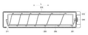
- FIG. 2 is a schematic longitudinal sectional view of the developer cartridge 20 according to an embodiment.
- FIG. 3 is a transverse sectional view of the developer cartridge 20 according to an embodiment.
- the developer cartridge 20 may include a housing 210 , a spiral coil 220 , and a developer bag 230 .
- the housing 210 is provided with a developer outlet 211 .
- a developer is supplied to the developing unit 10 through the developer outlet 211 .
- a supply line ( 40 of FIG. 1 ) may be connected to the developer outlet 211 .
- the developer outlet 211 may be connected to a supply unit ( 30 of FIG. 1 ).
- the developer outlet 211 may be directly connected to the developing unit 10 .
- the developer outlet 211 may be provided at one side of a longitudinal direction L of, for example, the housing 210 .
- a conveying member is provided inside the housing 210 for conveying the developer to the developer outlet 211 while being rotated.
- the conveying member may be a spiral member.
- the spiral coil 220 is an example of the conveying member.
- a power transmission member 240 is provided on one side wall 212 in the longitudinal direction L of the housing 210 .
- One end 221 of the spiral coil 220 is connected to the power transmission member 240 .
- the power transmission member 240 may be, for example, a gear, a coupler, or the like.
- the power transmission member 240 may be connected to a motor (not shown) provided in the main body 1 .
- the power transmission member 240 may be connected to a motor (not shown) provided in the developer cartridge 20 .
- the developer is contained in the developer bag 230 .
- the developer bag 230 is provided with an opening 233 through which the developer is discharged into the housing 210 .
- the opening 233 may be provided at a position not overlapping with the developer outlet 211 .
- the opening 233 is spaced from the developer outlet 211 in the longitudinal direction L. If the opening 233 and the developer outlet 211 overlap each other, the developer discharged from the developer bag 230 through the opening 233 is directly discharged to the outside of the developer cartridge 20 through the developer outlet 211 . Then, the developer is temporarily supplied excessively to the developing unit 10 , which may cause a poor image density or developer leakage.
- the developer discharged from the developer bag 230 through the opening 233 is conveyed in the longitudinal direction L by the spiral coil 220 inside the housing 210 and is conveyed to the developer outlet 211 . Therefore, the developer may be stably and uniformly discharged through the developer outlet 211 .
- the developer bag 230 is installed in the housing 210 and rotated.
- the developer bag 230 may be connected to the conveying member and rotated.
- the developer bag 230 may be rotated by a rotational force from the conveying member.
- the spiral coil 220 is employed as the conveying member, and the developer bag 230 is inserted into a central portion (an inner diameter portion) of the spiral coil 220 .
- An outer diameter of the developer bag 230 may be slightly larger than an inner diameter of the spiral coil 220 .
- the spiral coil 220 presses the developer bag 230 .
- the conveying member does not necessarily have to be the spiral coil 220 but may be in various forms having a central portion into which the developer bag 230 is inserted.
- the developer bag 230 is formed of a flexible material.
- the developer bag 230 may be formed of a material having a surface with a low coefficient of friction.
- the developer bag 230 may be formed of, for example, a PE sheet (Polyethylene sheet), an LDPE sheet (Low Density Polyethylene sheet), or a PA sheet (Polyamide sheet).
- the developer bag 230 includes a flexible wall 231 and a support wall 232 for retaining a shape of the developer bag 230 filled with gas, e.g., air, therein.
- the flexible space 231 and the support wall 232 form an accommodation space A in which the developer is accommodated.
- the support wall 232 provides rigidity to the developer bag 230 so that the developer bag 230 does not twist when the developer main merge 230 is rotated.
- FIG. 4 is a schematic cross-sectional view of the developer cartridge 20 according to an embodiment.
- a first sealing member 250 that seals the opening 233 is illustrated.
- the first sealing member 250 is attached to the flexible wall 231 to seal the opening 233 .
- the first sealing member 250 is bent in a U-shape and extends to the outside of the housing 210 through an outlet 213 provided in the side wall 212 of the housing 210 .
- a second sealing member 260 may be provided to prevent the developer from leaking through the outlet 213 .
- the second sealing member 260 may be formed of, for example, a sponge capable of being elastically deformed and restored.
- Shapes of the flexible wall 231 and the support wall 232 forming the developer bag 230 may vary.
- FIGS. 5A and 5B are a plan view and a cross-sectional view of the developer bag 230 , respectively, according to an embodiment.
- the developer bag 230 includes an inner wall 231 a defining the accommodation space A and an outer wall 232 a spaced apart and outward from the inner wall 231 a to create, together with the inner wall 231 a , a filling space B in which gas 23 e is filled.
- the flexible wall 231 is realized by the inner wall 231 a .
- the support wall 232 is realized by the inner wall 231 a and the outer wall 232 a which are spaced apart from each other.
- a part 231 b of the inner wall 231 a is exposed to the outside.
- An opening 233 is formed in the exposed part 231 b .
- a corner 233 a of the opening 233 has a round shape. Thereby, a possibility that the opening 233 is torn may be reduced.
- the opening 233 may be enclosed by the support wall 232 . Thus, a shape of the opening 233 is maintained, and the developer may be easily discharged into the housing 210 through the opening 233 .
- the developer cartridge 20 shown in FIGS. 5A and 5B has a structure in which the support wall 232 is formed entirely outside the flexible wall 231 excluding the portion where the opening 233 is formed but the shape of the developer cartridge 20 is not limited thereto.
- FIG. 6A is a partial longitudinal cross-sectional view of the developer bag 230 according to an embodiment.
- a plurality of partition walls 234 are provided between the inner wall 231 a and the outer wall 232 a .
- a filling space B between the inner wall 231 a and the outer wall 232 a may be divided into a first space B 1 in which gas is filled and a second space B 2 in which gas is not filled due to the plurality of partition walls 234 .
- the first space B 1 and the second space B 2 may extend in the longitudinal direction L of the developer bag 230 .
- FIG. 6B is a partial longitudinal cross-sectional view of the developer bag 230 according to an embodiment.
- the accommodation space A is formed by the flexible wall 231 , and the plurality of support walls 232 that are convex outward with respect to the flexible wall 231 may be arranged in a circumferential direction of the flexible wall 231 .
- the plurality of support walls 232 may extend in the longitudinal direction L of the developer bag 230 .
- FIG. 6C is a partial longitudinal cross-sectional view of the developer bag 230 according to an embodiment.
- the accommodation space A is formed by the flexible wall 231 , and the plurality of support walls 232 that are convex inward with respect to the flexible wall 231 may be arranged in a circumferential direction of the flexible wall 231 .
- the plurality of support walls 232 may extend in the longitudinal direction L of the developer cartridge 20 .
- FIG. 6D is a partial longitudinal cross-sectional view of the developer bag 230 according to an embodiment.
- the accommodation space A is formed by the flexible wall 231 , and the plurality of support walls 232 that are convex inward and outward with respect to the flexible wall 231 may be arranged in a circumferential direction of the flexible wall 231 .
- the plurality of support walls 232 may extend in the longitudinal direction L of the developer bag 230 .
- the developer bag 230 may be provided with a structure to be filled with a developer and gas.
- FIGS. 7A and 7B are side views of the developer bag 230 , showing an example of a structure to be filled with the developer and gas. Referring to FIGS. 7A and 7B , one end of the developer bag 230 is provided with the developer loading inlet 235 communicating with the accommodation space A and a gas filling inlet 236 communicating with the filling space B of the support wall 232 .
- the numbers and shapes of the developer loading inlet 235 and the gas filling inlet 236 are not limited to the examples shown in FIGS. 7A and 7B .
- the plurality of first spaces B 1 may communicate with the gas filling inlet 236 in series or in parallel.
- the plurality of support walls 232 may communicate with the gas filling inlet 236 in series or in parallel. Gas is injected into the filling space B through the gas filling inlet 236 .
- the support wall 232 is formed, and the developer bag 230 is expanded to form the accommodation space A.
- the gas filling inlet 236 is closed by, for example, heat fusion, ultrasonic welding or the like. A shape of the developer bag 230 is maintained by the support wall 232 .
- the developer is loaded into the accommodation space A through the developer loading inlet 235 with the opening 233 closed by the first sealing member 250 .
- the shape of the developer bag 230 is maintained by the support wall 232 , and thus the developer may be stably loaded into the accommodation space A. Thereafter, the developer loading inlet 235 may be closed by, for example, heat fusion, ultrasonic fusion, or the like.
- the developer bag 230 filled with gas and loaded with the developer is inserted into the central portion (the inner diameter portion) of the spiral coil 220 .
- the first sealing member 250 is removed before the developer cartridge 20 is mounted on the main assembly 1 .
- the developer is discharged into the housing 210 through the opening 233 .
- the spiral coil 220 is rotated, the developer bag 230 rotates together.
- the inner developer inside the developer bag 230 may be easily discharged into the housing 210 through the opening 233 by the rotation of the developer bag 230 .
- the developer may be unevenly distributed in the housing 210 in a longitudinal direction as the developer is consumed.
- the spiral coil 220 is partly overloaded, and there is a danger of disconnection of a drive motor (not shown) and deformation or breakage of the spiral coil 220 .
- the developer cartridge 20 of the present embodiment employing the developer bag 230 since the developer bag 230 is inserted into the central portion of the spiral coil 220 , and a shape of the developer bag 230 is maintained, an excessive driving load is not applied to the spiral coil 220 , and a risk of deformation of the spiral coil 220 may be reduced.
- the developer in the developer bag 230 may be held in a powder state without being clustered by the rotational vibration and the elasticity of the developer bag 230 .
- a manufacturing process includes a filling process of filling the developer directly to the housing 210 . Therefore, when a problem occurs in the filling process, the entire manufacturing process is affected.
- the process of filling the developer in the developer bag 230 may be realized as an independent process, the developer bag 230 in which the developer is filled may be supplied as a part to the manufacturing process of the developer cartridge 20 . Therefore, the process efficiency may be improved. Further, since the developer is not exposed to the outside in the manufacturing process of the developer cartridge 20 , the process cleanliness may be improved.
- the shape and the number of the openings 233 are not particularly limited as long as the openings 233 and the developer outlet 211 do not overlap each other.
- FIGS. 8A through 8G show examples of a shape of the opening 233 .
- the opening 233 may have a rectangular shape. At this time, corners may be rounded so that the opening 233 is not tom.
- the opening 233 may be positioned on the opposite side of the developer outlet 211 in the longitudinal direction L of the developer bag 230 as shown in FIG. 8A .
- the opening 233 may be positioned nearer to the developer outlet 211 in the longitudinal direction L of the developer bag 230 as shown in FIG. 8B .
- the plurality of openings 233 may be arranged in the longitudinal direction L as shown in FIG. 8C .
- the opening 233 may be elongated from the opposite end of the developer outlet 211 to a position not overlapping the developer outlet 211 as shown in FIG. 8G .
- the opening 233 may be elliptical with a long axis in the longitudinal direction L.
- the plurality of circular openings 233 may be arranged in the longitudinal direction L as shown in FIG. 8E .
- the plurality of circular openings 233 may be arranged in a zigzag manner in the longitudinal direction L.
- FIG. 9A is a partial cross-sectional view of the developer cartridge 20 according to an embodiment. Referring to FIG. 9A , a stopper 270 is provided in the developer bag 230 .
- the stopper 270 may include a hook which is caught at an end portion 221 of the spiral coil 220 , for example, the opposite end of the developer outlet 211 of the spiral coil 220 .
- the developer bag 230 may be prevented from being pushed toward the developer discharge port 211 .
- FIGS. 9B and 9C are perspective views of the developer bag 230 in which the stopper 270 is employed according to an embodiment.
- the stopper 270 may include a ring protruding from an end of the developer bag 230 .
- the stopper 270 may include a ring that passes through the end of the developer bag 230 .
- FIG. 10 is a perspective view of the developer bag 230 according to an embodiment.
- a part of the support wall 232 forming the developer bag 230 has a spiral shaped portion 237 projecting outwardly from the developer bag 230 .
- a spiral direction of the spiral shaped portion 237 is the same as a spiral direction of the spiral coil 220 . According to this configuration, when the developer bag 230 rotates together with the spiral coil 220 , the developer inside the housing 210 may be conveyed to the developer outlet 211 by the spiral portion 237 . Therefore, the developer may be stably and effectively conveyed to the developer outlet 211 .
- FIGS. 11A and 11B are plan views showing a shape of the opening 233 of the developer bag 230 shown in FIG. 10 according to an embodiment.
- the support wall 232 includes an opening forming wall 238 extending in the longitudinal direction L around the opening 233 to maintain the shape of the opening 233 .
- the support wall 232 includes an opening forming wall 238 that surrounds the opening 233 with the spiral shaped portion 237 to maintain the shape of the opening 233 .
- a shape in which the opening 233 is formed in the flexible wall 231 surrounded by the spiral shaped portion 237 and the opening forming wall 238 may be realized.
Landscapes
- Physics & Mathematics (AREA)
- General Physics & Mathematics (AREA)
- Dry Development In Electrophotography (AREA)
Abstract
Description
Claims (20)
Applications Claiming Priority (2)
| Application Number | Priority Date | Filing Date | Title |
|---|---|---|---|
| KR10-2016-0162923 | 2016-12-01 | ||
| KR1020160162923A KR20180062818A (en) | 2016-12-01 | 2016-12-01 | developer cartridge and electrophotographic image forming apparatus using the same |
Publications (2)
| Publication Number | Publication Date |
|---|---|
| US20180157193A1 US20180157193A1 (en) | 2018-06-07 |
| US10073378B2 true US10073378B2 (en) | 2018-09-11 |
Family
ID=62240099
Family Applications (1)
| Application Number | Title | Priority Date | Filing Date |
|---|---|---|---|
| US15/693,780 Active US10073378B2 (en) | 2016-12-01 | 2017-09-01 | Developer cartridge and electrophotographic image forming apparatus employing the same |
Country Status (4)
| Country | Link |
|---|---|
| US (1) | US10073378B2 (en) |
| KR (1) | KR20180062818A (en) |
| CN (1) | CN109564401B (en) |
| WO (1) | WO2018101579A1 (en) |
Families Citing this family (1)
| Publication number | Priority date | Publication date | Assignee | Title |
|---|---|---|---|---|
| KR20200116227A (en) * | 2019-04-01 | 2020-10-12 | 휴렛-팩커드 디벨롭먼트 컴퍼니, 엘.피. | Developer cartridge being capable of adjusting inside volume thereof |
Citations (7)
| Publication number | Priority date | Publication date | Assignee | Title |
|---|---|---|---|---|
| EP0518682B1 (en) | 1991-06-14 | 1995-08-23 | Oki Electric Industry Co., Ltd. | Developing device |
| US20070019994A1 (en) | 2005-06-02 | 2007-01-25 | Samsung Electronics Co., Ltd. | Electrophotographic color image forming apparatus |
| US20100254732A1 (en) | 2004-08-16 | 2010-10-07 | Nobuyuki Taguchi | Method and toner bottle for image forming apparatus capable of effectively supplying toner to image forming apparatus |
| US20140119780A1 (en) | 2009-09-04 | 2014-05-01 | Eisuke Hori | Toner container, image forming apparatus including same, and connecting structure for connecting toner container and image forming apparatus |
| US9285707B2 (en) | 2011-11-29 | 2016-03-15 | Canon Kabushiki Kaisha | Developer accommodating unit with a urging member for urging a flexible member |
| US20160170356A1 (en) | 2014-12-15 | 2016-06-16 | Hiroyuki Mabuchi | Toner bottle driving device control method and image forming apparatus |
| US20170285527A1 (en) * | 2016-03-31 | 2017-10-05 | Brother Kogyo Kabushiki Kaisha | Developer Cartridge Provided with Casing and Developer Accommodating Unit Detachably Supported Thereto |
Family Cites Families (6)
| Publication number | Priority date | Publication date | Assignee | Title |
|---|---|---|---|---|
| US6017118A (en) * | 1995-04-27 | 2000-01-25 | Hewlett-Packard Company | High performance ink container with efficient construction |
| JP5540759B2 (en) * | 2010-02-22 | 2014-07-02 | コニカミノルタ株式会社 | Toner storage container and image forming apparatus using toner storage container |
| CN102331694B (en) * | 2011-07-18 | 2014-08-27 | 珠海天威飞马打印耗材有限公司 | Electronic camera imaging equipment |
| JP2013142723A (en) * | 2012-01-06 | 2013-07-22 | Sharp Corp | Toner supply device, toner storage unit, pressing unit, and image forming apparatus |
| CN103777499A (en) * | 2014-02-28 | 2014-05-07 | 许红洋 | Carbon powder feeding device of laser printer and laser duplicating all-in-one machine and application method of carbon powder feeding device |
| CN204964991U (en) * | 2015-07-15 | 2016-01-13 | 珠海市汇威打印机耗材有限公司 | Compatible toner cartridge |
-
2016
- 2016-12-01 KR KR1020160162923A patent/KR20180062818A/en not_active Withdrawn
-
2017
- 2017-09-01 US US15/693,780 patent/US10073378B2/en active Active
- 2017-09-04 CN CN201780047029.7A patent/CN109564401B/en not_active Expired - Fee Related
- 2017-09-04 WO PCT/KR2017/009632 patent/WO2018101579A1/en active Application Filing
Patent Citations (7)
| Publication number | Priority date | Publication date | Assignee | Title |
|---|---|---|---|---|
| EP0518682B1 (en) | 1991-06-14 | 1995-08-23 | Oki Electric Industry Co., Ltd. | Developing device |
| US20100254732A1 (en) | 2004-08-16 | 2010-10-07 | Nobuyuki Taguchi | Method and toner bottle for image forming apparatus capable of effectively supplying toner to image forming apparatus |
| US20070019994A1 (en) | 2005-06-02 | 2007-01-25 | Samsung Electronics Co., Ltd. | Electrophotographic color image forming apparatus |
| US20140119780A1 (en) | 2009-09-04 | 2014-05-01 | Eisuke Hori | Toner container, image forming apparatus including same, and connecting structure for connecting toner container and image forming apparatus |
| US9285707B2 (en) | 2011-11-29 | 2016-03-15 | Canon Kabushiki Kaisha | Developer accommodating unit with a urging member for urging a flexible member |
| US20160170356A1 (en) | 2014-12-15 | 2016-06-16 | Hiroyuki Mabuchi | Toner bottle driving device control method and image forming apparatus |
| US20170285527A1 (en) * | 2016-03-31 | 2017-10-05 | Brother Kogyo Kabushiki Kaisha | Developer Cartridge Provided with Casing and Developer Accommodating Unit Detachably Supported Thereto |
Also Published As
| Publication number | Publication date |
|---|---|
| CN109564401A (en) | 2019-04-02 |
| CN109564401B (en) | 2021-08-31 |
| KR20180062818A (en) | 2018-06-11 |
| WO2018101579A1 (en) | 2018-06-07 |
| US20180157193A1 (en) | 2018-06-07 |
Similar Documents
| Publication | Publication Date | Title |
|---|---|---|
| CN102621852B (en) | Developer cartridge, image forming unit and image forming apparatus | |
| JP2007298543A (en) | Toner cartridge | |
| EP3282321B1 (en) | Development cartridge and electrophotographic image forming apparatus adopting the same | |
| EP3195065A1 (en) | Powder container and image forming apparatus | |
| US9158269B2 (en) | Electrophotographic image forming apparatus having a stable connection of a developer cartridge and toner cartridge | |
| US9983507B1 (en) | Developer cartridge and electrophotographic image forming apparatus employing the same | |
| CN102193395B (en) | Powder transporting unit and image forming apparatus using the same | |
| JP2025113321A (en) | Consumables storage container, device, image forming apparatus, refillable consumables storage container, and consumables supply system | |
| US10073378B2 (en) | Developer cartridge and electrophotographic image forming apparatus employing the same | |
| CN101644908A (en) | Developer supply cartridge, image forming method and image forming apparatus | |
| JP2015230408A (en) | Member for image formation apparatus, and image formation apparatus with the same | |
| JP4844222B2 (en) | Toner cartridge | |
| JP4756065B2 (en) | Developer container, developing device, and image forming apparatus | |
| AU2007201594B2 (en) | Toner cartridge and image forming apparatus | |
| EP3762782B1 (en) | Development cartridge with developer inlet for refilling developer and cap sealing developer inlet | |
| US11415910B2 (en) | Developing apparatus having a sealed developer opening | |
| US10048639B2 (en) | Unidirectional clutch and electrophotographic image forming apparatus employing the same | |
| US12099316B2 (en) | Developing device and image forming apparatus that suppress discharge of developer | |
| JP2024135553A (en) | Sealing cap, toner container and image forming apparatus | |
| WO2024039410A1 (en) | Position of toner outlet for toner cartridge | |
| JP4926693B2 (en) | Developing device, developing unit, image forming apparatus | |
| JP2009244451A (en) | Developing device, and image forming apparatus equipped therewith | |
| JP2011141317A (en) | Lubricant applying apparatus, process cartridge, image forming apparatus | |
| JP2014232139A (en) | Developing apparatus, process cartridge, and image forming apparatus |
Legal Events
| Date | Code | Title | Description |
|---|---|---|---|
| AS | Assignment |
Owner name: S-PRINTING SOLUTION CO., LTD., KOREA, REPUBLIC OF Free format text: ASSIGNMENT OF ASSIGNORS INTEREST;ASSIGNORS:KIM, JIN-HONG;LEE, JAE-RAE;LEE, HO-YOUNG;REEL/FRAME:043471/0246 Effective date: 20170830 |
|
| FEPP | Fee payment procedure |
Free format text: ENTITY STATUS SET TO UNDISCOUNTED (ORIGINAL EVENT CODE: BIG.); ENTITY STATUS OF PATENT OWNER: LARGE ENTITY |
|
| AS | Assignment |
Owner name: HP PRINTING KOREA CO., LTD., KOREA, REPUBLIC OF Free format text: CHANGE OF NAME;ASSIGNOR:S-PRINTING SOLUTION CO., LTD.;REEL/FRAME:047370/0405 Effective date: 20180316 |
|
| STCF | Information on status: patent grant |
Free format text: PATENTED CASE |
|
| AS | Assignment |
Owner name: HP PRINTING KOREA CO., LTD., KOREA, REPUBLIC OF Free format text: CORRECTIVE ASSIGNMENT TO CORRECT THE DOCUMENTATION EVIDENCING THE CHANGE OF NAME PREVIOUSLY RECORDED ON REEL 047370 FRAME 0405. ASSIGNOR(S) HEREBY CONFIRMS THE CHANGE OF NAME;ASSIGNOR:S-PRINTING SOLUTION CO., LTD.;REEL/FRAME:047769/0001 Effective date: 20180316 |
|
| CC | Certificate of correction | ||
| AS | Assignment |
Owner name: HP PRINTING KOREA CO., LTD., KOREA, REPUBLIC OF Free format text: CHANGE OF LEGAL ENTITY EFFECTIVE AUG. 31, 2018;ASSIGNOR:HP PRINTING KOREA CO., LTD.;REEL/FRAME:050938/0139 Effective date: 20190611 |
|
| AS | Assignment |
Owner name: HEWLETT-PACKARD DEVELOPMENT COMPANY, L.P., TEXAS Free format text: CONFIRMATORY ASSIGNMENT EFFECTIVE NOVEMBER 1, 2018;ASSIGNOR:HP PRINTING KOREA CO., LTD.;REEL/FRAME:050747/0080 Effective date: 20190826 |
|
| MAFP | Maintenance fee payment |
Free format text: PAYMENT OF MAINTENANCE FEE, 4TH YEAR, LARGE ENTITY (ORIGINAL EVENT CODE: M1551); ENTITY STATUS OF PATENT OWNER: LARGE ENTITY Year of fee payment: 4 |