US1007331A - Double-acting two-cycle internal-combustion engine. - Google Patents
Double-acting two-cycle internal-combustion engine. Download PDFInfo
- Publication number
- US1007331A US1007331A US37690707A US1907376907A US1007331A US 1007331 A US1007331 A US 1007331A US 37690707 A US37690707 A US 37690707A US 1907376907 A US1907376907 A US 1907376907A US 1007331 A US1007331 A US 1007331A
- Authority
- US
- United States
- Prior art keywords
- piston
- cylinder
- double
- acting
- chamber
- Prior art date
- Legal status (The legal status is an assumption and is not a legal conclusion. Google has not performed a legal analysis and makes no representation as to the accuracy of the status listed.)
- Expired - Lifetime
Links
- 238000002485 combustion reaction Methods 0.000 title description 6
- 239000002360 explosive Substances 0.000 description 7
- 241001474728 Satyrodes eurydice Species 0.000 description 5
- 230000006835 compression Effects 0.000 description 2
- 238000007906 compression Methods 0.000 description 2
- 238000010276 construction Methods 0.000 description 2
- 238000004880 explosion Methods 0.000 description 2
- 239000007789 gas Substances 0.000 description 2
- 239000000203 mixture Substances 0.000 description 2
- 238000012856 packing Methods 0.000 description 2
- 206010043268 Tension Diseases 0.000 description 1
- 230000006872 improvement Effects 0.000 description 1
- 239000000463 material Substances 0.000 description 1
Images


Classifications
-
- F—MECHANICAL ENGINEERING; LIGHTING; HEATING; WEAPONS; BLASTING
- F02—COMBUSTION ENGINES; HOT-GAS OR COMBUSTION-PRODUCT ENGINE PLANTS
- F02B—INTERNAL-COMBUSTION PISTON ENGINES; COMBUSTION ENGINES IN GENERAL
- F02B75/00—Other engines
- F02B75/002—Double acting engines
Definitions
- This invention relates to a double acting two cycleinternal combustion engine, and consists in the construction and arrangement of parts hereinafter fully set forth and pointed out particularly in the claim.
- the object of the invention is to produce an engine of the character described, of compact and simple construction wherein the arrangement is such as to provide for exploding a charge alternately in the opposite ends of the working cylinder and for compressing the explosive charges within the piston and forcing said charges alternately from the opposite ends' of.- the piston into the ends of the cylinder prior to com pression by the moving piston and ignition,-
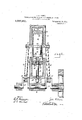
- FIG. l is a central, vertical section through an engine involving my invention, said section being at right an les to the crank shaft.
- Fig. 2 is a similar section parallel with the crank shaft.
- Fig. 3 is a plan view of the fixed piston "within the movable piston of the engine.
- Fig. 4 is alongitudinal section therethrouglr as on line 4% of Fig. 3.
- Fig. 5 is an inverted plan view of said fixed piston.
- Fig. 6 is a horizontal section through the main cylinder as on line 66 of Fig 1.
- Fig. 7 is a longitudinal sect-ional].view through the double check valve case which is screwed into the fixed piston for purposes hereinafter explained.
- Fig. 8 is an end view of Fig. 7.
- Fig. 9 is a fragmentary view. in section through the upper end of the main cylinder showing the manner of connecting the parts thereof.
- 1 designates the base formed integral with the lower end of the main cylinder 2 which supported thereon.
- the crank shaft 3 is suitably journaled below the base of the cylinder.
- the cylinder by suitable tie oolts 5 passing ver tically therethrough, as'clearly shown in Fig. 9.
- the cylinder is thetnovalole motor piston 6 which is formed hollow and is provided at one end with a removable head 7.
- Said piston is of the double-acting type and is provided at its opposite ends with suitable packing rings 8.
- Intermediate the ends of the cylinder, the wall thereof on opposite sides is provided with a slot 9, and formed .integral with the piston and projecting laterally therefrom through said slots are the journal pins 10 on which are journaled the upper ends of the connecting rods 11.
- the lowerends of said connect ing rods are journaled on the pins 12 of the cranks 13 of the shaft 3.
- the movable or motor piston is a stationary piston 14: having a central chamber 15 therein.
- the stationary piston is supported within the movable piston by means of the hollow standard 16 which at its upper end is threaded and screwed into thetapped opening 1? in the lower end'of said stationary piston, said standard passmg through the head 7 of the movable p1ston 6 in which is formed a suitable stutiing I box'lS which embraces said standard, the
- valve cage 26 Screwed into the openings 23 and 25 so as to" render it removable therefrom is a valve cage 26 having, at its upper end a check valve 27, and at its lower end a check valve 28, said valves being adapted to seat upon the opposite ends of said cage to close the passage therethrough.
- an opening 29 In the wall of the cage is an opening 29 which establishes communication between the valve cage and the chamber 15.
- said chamber is placed in communication with the opposite ends of the piston 6 through the valve-controlled openings in the opposite ends of said cage.
- Suitable packing rings 30 are employed between the ends of the stationary piston and the inner wall of v themovable piston.
- a port 31 Formed through the wall of the movable 'piston at its upper end is a port 31, and in the wall of said piston at its lower end is a similar port 32.
- a bypass 33 In the wall of the cylinder is a bypass 33 with which the upper port in the piston 6 is adapted to register.
- a second hy-pass 34 is also formed in the.
- An exhaust port 35 is goiormed through the wall of the cylinder at the upper end thereof with whichthe exhaust pipe 36 communicates, and at the lower end of said cylinder is an exhaust port 37 communicating with the exhaust 3'5'pipe 38, said exhaust pipes 36 and 38 connesting. with a single exhaust pipe 39.
- the compressed charge in chamber 40 in compressing the charge in the chamber the compressed charge in chamber 40 willpass around the lower head of said piston into the lower end of the cylinder in posi-' tion for compression by a return stroke of 40, the area of the chamber el at the upper end of the movable piston is greatly in- "creased causing a partial vacuum therein and an inflow of the explosive mixture whichis again drawn through the hollow standard l6-into the chamber 15 of the stationary piston and past the valve 27 into said chamber 41 so that upon the return stroke of the piston 6' the explosive charge in chamber .41 is compressed until the movement of the piston causes the port 31 to register with the lower end ofthe bypass 33, when said charge will escape under pressure into the upper end of the cylinder.
- valves 27 and 28 are connectedby a coiled spring 42, the ten sion of which will normally hold said valves to their seat, but which will yield sufficiently to allow said valves to rise to permit an explosive charge to pass into the opposite ends of the movable piston, as before described.
- each end of the piston is provided with a curved deflector 43 which extends around the inlet port of the by-pass so that the inrushing charge is deflected upwardly into the cylinder to-prevent its escape with the exhaust. It will now be apparent that a reciprocation of the main piston 6 will cause an explosive charge to be alternately introduced into the opposite ends of the cylinder, which charges are successively compressed by the" return stroke of the piston and exploded by the ordinary ignition device in common use, affording two impulses for each revolution of the engine shaft.
Landscapes
- Engineering & Computer Science (AREA)
- Chemical & Material Sciences (AREA)
- Combustion & Propulsion (AREA)
- Mechanical Engineering (AREA)
- General Engineering & Computer Science (AREA)
- Output Control And Ontrol Of Special Type Engine (AREA)
Description
J. E. BROWN. DOUBLE'ACTING TWO CYCLE INTERNAL COMBUSTION ENGINE.
ALPLIGATION FILED JUNES, 1907. LQQTK ES 1 Patented Oct. 31, 1911.
3 SHEETS-SHEET 1.
' witnesses inventor 1. E. BROWN. DOUBLE Q AGTING TWO CYCLE INTERNAL COMBUSTION ENGINE.
APPLIUATION FILED JUNE 3, 1907.
1,007,331. Patented 001. 31, 1911.
3 SHEETSSHBET 2.
Wit ncsses Ma g J. E. BROWN.
DOUBLE ACTING TWO CYCLE INTERNAL COMBUSTION ENGINE.
APPLICATION FILED JUNE 3, 1907.
1,007,331, Patented Cct.31,1911.
uhtncsscs mum Y enrrnn sra'rnis JOHN E. BROWN, OF SARNIA,'O1\TTARIO, CANADA, ASSIGNOR 0F ONE-HALF TO LUKE W.
rarest crates.
TURNBULL, or Pon'r HURON, MICHiGAN:
DOUBLE-ACTING TWO-CYCLE INTERNAIrCOM BUSTION ENGINE.
Specification of Letters Patent.
Application filed June 3, 1907. Serial No. 376,907.
vented certain new and useful Improve ments in Double-Acting TwoC-ycle Internal-Combustion Engines; and I do declare the following to be a full. clear, and exactdescription of the invention, such as will enable others skilled in the art to which it appertains to make and use the same, reference being had to theaccoin'panying drawings, and to the figures of reference marked thereon, which form a part of this specifica tion.
This invention relates to a double acting two cycleinternal combustion engine, and consists in the construction and arrangement of parts hereinafter fully set forth and pointed out particularly in the claim.
The object of the invention is to produce an engine of the character described, of compact and simple construction wherein the arrangement is such as to provide for exploding a charge alternately in the opposite ends of the working cylinder and for compressing the explosive charges within the piston and forcing said charges alternately from the opposite ends' of.- the piston into the ends of the cylinder prior to com pression by the moving piston and ignition,-
as will be well understood in the art.
The above object is attained by the structure illustrated in the accompanying drawing, in which I Figure l is a central, vertical section through an engine involving my invention, said section being at right an les to the crank shaft. Fig. 2 is a similar section parallel with the crank shaft. Fig. 3 is a plan view of the fixed piston "within the movable piston of the engine. Fig. 4 is alongitudinal section therethrouglr as on line 4% of Fig. 3. Fig. 5 is an inverted plan view of said fixed piston. Fig. 6 is a horizontal section through the main cylinder as on line 66 of Fig 1. Fig. 7 is a longitudinal sect-ional].view through the double check valve case which is screwed into the fixed piston for purposes hereinafter explained. Fig. 8 is an end view of Fig. 7. Fig. 9 is a fragmentary view. in section through the upper end of the main cylinder showing the manner of connecting the parts thereof.
Referring to the characters of reference, 1 designates the base formed integral with the lower end of the main cylinder 2 which supported thereon. The crank shaft 3 is suitably journaled below the base of the cylinder. For the purpose of affording ready access to the interior of the cylinder, the
upper or cap port-ion thereof is made detachable and is secured to the body of the Patented Got. 31, P911.
cylinder by suitable tie oolts 5 passing ver tically therethrough, as'clearly shown in Fig. 9. Vithin the cylinder is thetnovalole motor piston 6 which is formed hollow and is provided at one end with a removable head 7. Said piston is of the double-acting type and is provided at its opposite ends with suitable packing rings 8. Intermediate the ends of the cylinder, the wall thereof on opposite sides is provided with a slot 9, and formed .integral with the piston and projecting laterally therefrom through said slots are the journal pins 10 on which are journaled the upper ends of the connecting rods 11. The lowerends of said connect ing rods are journaled on the pins 12 of the cranks 13 of the shaft 3.
YVithin the movable or motor piston is a stationary piston 14: having a central chamber 15 therein. The stationary piston .is supported within the movable piston by means of the hollow standard 16 which at its upper end is threaded and screwed into thetapped opening 1? in the lower end'of said stationary piston, said standard passmg through the head 7 of the movable p1ston 6 in which is formed a suitable stutiing I box'lS which embraces said standard, the
lower end of said standard passing through I a tapered aperture in the lower cylinder head and receiving the nut 19 by means of which it may be drawn tightly into place. Connected with the lower end of said standard is an elbow :20 with which is connected communicateswith said chambenandformed through the lower end of said piston is port 24 having a tapped portion 25 communicating with said central chamber.
Screwed into the openings 23 and 25 so as to" render it removable therefrom is a valve cage 26 having, at its upper end a check valve 27, and at its lower end a check valve 28, said valves being adapted to seat upon the opposite ends of said cage to close the passage therethrough. In the wall of the cage is an opening 29 which establishes communication between the valve cage and the chamber 15. By this arrangement said chamber is placed in communication with the opposite ends of the piston 6 through the valve-controlled openings in the opposite ends of said cage.. Suitable packing rings 30 are employed between the ends of the stationary piston and the inner wall of v themovable piston. I Formed through the wall of the movable 'piston at its upper end is a port 31, and in the wall of said piston at its lower end is a similar port 32. In the wall of the cylinder is a bypass 33 with which the upper port in the piston 6 is adapted to register.
A second hy-pass 34 is also formed in the.
wall of the cylinder near its lower end with which the lower port in said piston is adapt- ;ed' to register.v An exhaust port 35 is goiormed through the wall of the cylinder at the upper end thereof with whichthe exhaust pipe 36 communicates, and at the lower end of said cylinder is an exhaust port 37 communicating with the exhaust 3'5'pipe 38, said exhaust pipes 36 and 38 connesting. with a single exhaust pipe 39.
In explaining the operation of the engine, reference will first bemade to Fig. 1, where: in the parts are in the position immediately 4] following the' exp'losion of a charge in the upper end'of the'cylinder, the piston 6 bein at the limit of its down stroke and the exhaust port 35 being uncovered by the piston to permit the burned gases to escape. As the piston 6 moves downwardly, the area of the chamber 40 therein below the stationary piston is greatly increased, causing a partial vacuum therein and a consequent inflow of explosive mixture which is drawn through the hollow standard 16 into the chamber 15 of the stationary, piston and past the valve 28 intothechamber 40; in the meantime the explosion of a second charge at the lower end of the cylinder will have driven the piston 6 upwardly, thereby compressing the charge in the chamber 40 until the movement of the piston 6 shall 'have caused the port 32 therein to register with the upper end of the by-pass 34, when ,7 the piston. As the piston 6 moves upwardly a? in compressing the charge in the chamber the compressed charge in chamber 40 willpass around the lower head of said piston into the lower end of the cylinder in posi-' tion for compression by a return stroke of 40, the area of the chamber el at the upper end of the movable piston is greatly in- "creased causing a partial vacuum therein and an inflow of the explosive mixture whichis again drawn through the hollow standard l6-into the chamber 15 of the stationary piston and past the valve 27 into said chamber 41 so that upon the return stroke of the piston 6' the explosive charge in chamber .41 is compressed until the movement of the piston causes the port 31 to register with the lower end ofthe bypass 33, when said charge will escape under pressure into the upper end of the cylinder. Itwill be noted that the valves 27 and 28 are connectedby a coiled spring 42, the ten sion of which will normally hold said valves to their seat, but which will yield sufficiently to allow said valves to rise to permit an explosive charge to pass into the opposite ends of the movable piston, as before described.
When the piston 6 is forced upwardly by the explosion of a charge in the lower end of the cylinder, the exhaust port 37 is uncovered at the time said piston reaches the limit of its upward movement, thereby allowing the burned gases to escape. It will be noted that each end of the piston is provided with a curved deflector 43 which extends around the inlet port of the by-pass so that the inrushing charge is deflected upwardly into the cylinder to-prevent its escape with the exhaust. It will now be apparent that a reciprocation of the main piston 6 will cause an explosive charge to be alternately introduced into the opposite ends of the cylinder, which charges are successively compressed by the" return stroke of the piston and exploded by the ordinary ignition device in common use, affording two impulses for each revolution of the engine shaft. It will be noted that this result is accomplished without a material elongation of the cylinder and without increasing its diameter at any point, the hollow motor piston in connection with the stationary piston therein serving as a pump to force the explosive charges successively into the ends of the cylinder, the stationary piston, the movable piston and the main cylinder being co-axial.
Having thus fully set forth my invention, what I claim as new and desire to secure by 'Letters Patent, is
The combination of a cylinder adapted to explode a charge at each end, a hollow reciprocatory piston therein, said piston having ports near the ends thereof, the wall of the cylinder having by-passesv therein which, open into the cylinder at each end, said bypasses adapted in. conjunction with said ports to establish communication between the interior of the hollow piston at its ends and the ends of the cylinder, the movable piston in its travel alternately opening and closing both ends of said by-passes, a stationary piston within the movable piston, said stationary piston having a chamber located centrally therein and having Valvecontrolled ports opening through the opposite ends thereof which connect the chamber of the stationary piston with the interior of the movable piston on each side of through one end of the movable piston, said hollow rod supporting the stationary pis ,ton and communicating at one end with the chamber therein independently of said 1.5 valve-controlled ports.
In testimony whereof, I sign this specification in the presence of two Witnesses. 7 JOHN E. BROWN; Witnesses:
P. H. PHILLIPS, W. L. JENKs.
Priority Applications (1)
| Application Number | Priority Date | Filing Date | Title |
|---|---|---|---|
| US37690707A US1007331A (en) | 1907-06-03 | 1907-06-03 | Double-acting two-cycle internal-combustion engine. |
Applications Claiming Priority (1)
| Application Number | Priority Date | Filing Date | Title |
|---|---|---|---|
| US37690707A US1007331A (en) | 1907-06-03 | 1907-06-03 | Double-acting two-cycle internal-combustion engine. |
Publications (1)
| Publication Number | Publication Date |
|---|---|
| US1007331A true US1007331A (en) | 1911-10-31 |
Family
ID=3075644
Family Applications (1)
| Application Number | Title | Priority Date | Filing Date |
|---|---|---|---|
| US37690707A Expired - Lifetime US1007331A (en) | 1907-06-03 | 1907-06-03 | Double-acting two-cycle internal-combustion engine. |
Country Status (1)
| Country | Link |
|---|---|
| US (1) | US1007331A (en) |
Cited By (1)
| Publication number | Priority date | Publication date | Assignee | Title |
|---|---|---|---|---|
| US3828741A (en) * | 1972-01-13 | 1974-08-13 | A Bixier | Internal combustion engine |
-
1907
- 1907-06-03 US US37690707A patent/US1007331A/en not_active Expired - Lifetime
Cited By (1)
| Publication number | Priority date | Publication date | Assignee | Title |
|---|---|---|---|---|
| US3828741A (en) * | 1972-01-13 | 1974-08-13 | A Bixier | Internal combustion engine |
Similar Documents
| Publication | Publication Date | Title |
|---|---|---|
| US1542578A (en) | Internal-combustion engine | |
| US928405A (en) | Internal-combustion engine. | |
| US886846A (en) | Explosive-engine. | |
| US1664091A (en) | Internal-combustion engine | |
| US1328141A (en) | Internal-combustion engine | |
| US1126713A (en) | Explosive-engine. | |
| US1149178A (en) | Internal-combustion engine. | |
| US1033160A (en) | Explosive-engine. | |
| US990082A (en) | Internal-combustion engine. | |
| US1955976A (en) | Internal combustion engine | |
| US1193610A (en) | Bayneb | |
| US1010353A (en) | Gas-engine valve. | |
| US954577A (en) | Gas-engine. | |
| US1065250A (en) | Two-stroke-cycle internal-combustion engine. | |
| US923069A (en) | Explosive-engine. | |
| US877483A (en) | Explosive-engine. | |
| US1240980A (en) | Internal-combustion engine. | |
| US1625638A (en) | Engine | |
| US952483A (en) | Explosive-engine. | |
| US1476308A (en) | Internal-combustion engine | |
| US1376800A (en) | Gas-engine | |
| US955144A (en) | Two-stroke-cycle internal-combustion engine. | |
| US1377661A (en) | Internal-combustion engine | |
| US1033911A (en) | Explosion-engine. | |
| US966309A (en) | Internal-combustion engine. |