US10072888B2 - Refrigerator - Google Patents

Refrigerator Download PDF

Info

Publication number
US10072888B2
US10072888B2 US14/803,248 US201514803248A US10072888B2 US 10072888 B2 US10072888 B2 US 10072888B2 US 201514803248 A US201514803248 A US 201514803248A US 10072888 B2 US10072888 B2 US 10072888B2
Authority
US
United States
Prior art keywords
cooling space
cool air
ice
storage compartment
refrigerator
Prior art date
Legal status (The legal status is an assumption and is not a legal conclusion. Google has not performed a legal analysis and makes no representation as to the accuracy of the status listed.)
Active, expires
Application number
US14/803,248
Other versions
US20160047591A1 (en
Inventor
Jin Jeong
Bong Su Son
Do Yun Jang
Yeon Woo CHO
Current Assignee (The listed assignees may be inaccurate. Google has not performed a legal analysis and makes no representation or warranty as to the accuracy of the list.)
Samsung Electronics Co Ltd
Original Assignee
Samsung Electronics Co Ltd
Priority date (The priority date is an assumption and is not a legal conclusion. Google has not performed a legal analysis and makes no representation as to the accuracy of the date listed.)
Filing date
Publication date
Application filed by Samsung Electronics Co Ltd filed Critical Samsung Electronics Co Ltd
Assigned to SAMSUNG ELECTRONICS CO., LTD. reassignment SAMSUNG ELECTRONICS CO., LTD. ASSIGNMENT OF ASSIGNORS INTEREST (SEE DOCUMENT FOR DETAILS). Assignors: CHO, YEON WOO, JANG, DO YUN, JEONG, JIN, SON, BONG SU
Publication of US20160047591A1 publication Critical patent/US20160047591A1/en
Application granted granted Critical
Publication of US10072888B2 publication Critical patent/US10072888B2/en
Active legal-status Critical Current
Adjusted expiration legal-status Critical

Links

Images

Classifications

    • FMECHANICAL ENGINEERING; LIGHTING; HEATING; WEAPONS; BLASTING
    • F25REFRIGERATION OR COOLING; COMBINED HEATING AND REFRIGERATION SYSTEMS; HEAT PUMP SYSTEMS; MANUFACTURE OR STORAGE OF ICE; LIQUEFACTION SOLIDIFICATION OF GASES
    • F25DREFRIGERATORS; COLD ROOMS; ICE-BOXES; COOLING OR FREEZING APPARATUS NOT OTHERWISE PROVIDED FOR
    • F25D23/00General constructional features
    • F25D23/02Doors; Covers
    • F25D23/028Details
    • FMECHANICAL ENGINEERING; LIGHTING; HEATING; WEAPONS; BLASTING
    • F25REFRIGERATION OR COOLING; COMBINED HEATING AND REFRIGERATION SYSTEMS; HEAT PUMP SYSTEMS; MANUFACTURE OR STORAGE OF ICE; LIQUEFACTION SOLIDIFICATION OF GASES
    • F25CPRODUCING, WORKING OR HANDLING ICE
    • F25C1/00Producing ice
    • F25C1/04Producing ice by using stationary moulds
    • FMECHANICAL ENGINEERING; LIGHTING; HEATING; WEAPONS; BLASTING
    • F25REFRIGERATION OR COOLING; COMBINED HEATING AND REFRIGERATION SYSTEMS; HEAT PUMP SYSTEMS; MANUFACTURE OR STORAGE OF ICE; LIQUEFACTION SOLIDIFICATION OF GASES
    • F25CPRODUCING, WORKING OR HANDLING ICE
    • F25C5/00Working or handling ice
    • F25C5/20Distributing ice
    • F25C5/22Distributing ice particularly adapted for household refrigerators
    • FMECHANICAL ENGINEERING; LIGHTING; HEATING; WEAPONS; BLASTING
    • F25REFRIGERATION OR COOLING; COMBINED HEATING AND REFRIGERATION SYSTEMS; HEAT PUMP SYSTEMS; MANUFACTURE OR STORAGE OF ICE; LIQUEFACTION SOLIDIFICATION OF GASES
    • F25DREFRIGERATORS; COLD ROOMS; ICE-BOXES; COOLING OR FREEZING APPARATUS NOT OTHERWISE PROVIDED FOR
    • F25D11/00Self-contained movable devices, e.g. domestic refrigerators
    • FMECHANICAL ENGINEERING; LIGHTING; HEATING; WEAPONS; BLASTING
    • F25REFRIGERATION OR COOLING; COMBINED HEATING AND REFRIGERATION SYSTEMS; HEAT PUMP SYSTEMS; MANUFACTURE OR STORAGE OF ICE; LIQUEFACTION SOLIDIFICATION OF GASES
    • F25DREFRIGERATORS; COLD ROOMS; ICE-BOXES; COOLING OR FREEZING APPARATUS NOT OTHERWISE PROVIDED FOR
    • F25D17/00Arrangements for circulating cooling fluids; Arrangements for circulating gas, e.g. air, within refrigerated spaces
    • F25D17/04Arrangements for circulating cooling fluids; Arrangements for circulating gas, e.g. air, within refrigerated spaces for circulating air, e.g. by convection
    • F25D17/06Arrangements for circulating cooling fluids; Arrangements for circulating gas, e.g. air, within refrigerated spaces for circulating air, e.g. by convection by forced circulation
    • F25D17/062Arrangements for circulating cooling fluids; Arrangements for circulating gas, e.g. air, within refrigerated spaces for circulating air, e.g. by convection by forced circulation in household refrigerators
    • F25D17/065Arrangements for circulating cooling fluids; Arrangements for circulating gas, e.g. air, within refrigerated spaces for circulating air, e.g. by convection by forced circulation in household refrigerators with compartments at different temperatures
    • FMECHANICAL ENGINEERING; LIGHTING; HEATING; WEAPONS; BLASTING
    • F25REFRIGERATION OR COOLING; COMBINED HEATING AND REFRIGERATION SYSTEMS; HEAT PUMP SYSTEMS; MANUFACTURE OR STORAGE OF ICE; LIQUEFACTION SOLIDIFICATION OF GASES
    • F25DREFRIGERATORS; COLD ROOMS; ICE-BOXES; COOLING OR FREEZING APPARATUS NOT OTHERWISE PROVIDED FOR
    • F25D21/00Defrosting; Preventing frosting; Removing condensed or defrost water
    • F25D21/14Collecting or removing condensed and defrost water; Drip trays
    • FMECHANICAL ENGINEERING; LIGHTING; HEATING; WEAPONS; BLASTING
    • F25REFRIGERATION OR COOLING; COMBINED HEATING AND REFRIGERATION SYSTEMS; HEAT PUMP SYSTEMS; MANUFACTURE OR STORAGE OF ICE; LIQUEFACTION SOLIDIFICATION OF GASES
    • F25DREFRIGERATORS; COLD ROOMS; ICE-BOXES; COOLING OR FREEZING APPARATUS NOT OTHERWISE PROVIDED FOR
    • F25D2317/00Details or arrangements for circulating cooling fluids; Details or arrangements for circulating gas, e.g. air, within refrigerated spaces, not provided for in other groups of this subclass
    • F25D2317/06Details or arrangements for circulating cooling fluids; Details or arrangements for circulating gas, e.g. air, within refrigerated spaces, not provided for in other groups of this subclass with forced air circulation
    • F25D2317/061Details or arrangements for circulating cooling fluids; Details or arrangements for circulating gas, e.g. air, within refrigerated spaces, not provided for in other groups of this subclass with forced air circulation through special compartments
    • FMECHANICAL ENGINEERING; LIGHTING; HEATING; WEAPONS; BLASTING
    • F25REFRIGERATION OR COOLING; COMBINED HEATING AND REFRIGERATION SYSTEMS; HEAT PUMP SYSTEMS; MANUFACTURE OR STORAGE OF ICE; LIQUEFACTION SOLIDIFICATION OF GASES
    • F25DREFRIGERATORS; COLD ROOMS; ICE-BOXES; COOLING OR FREEZING APPARATUS NOT OTHERWISE PROVIDED FOR
    • F25D2317/00Details or arrangements for circulating cooling fluids; Details or arrangements for circulating gas, e.g. air, within refrigerated spaces, not provided for in other groups of this subclass
    • F25D2317/06Details or arrangements for circulating cooling fluids; Details or arrangements for circulating gas, e.g. air, within refrigerated spaces, not provided for in other groups of this subclass with forced air circulation
    • F25D2317/062Details or arrangements for circulating cooling fluids; Details or arrangements for circulating gas, e.g. air, within refrigerated spaces, not provided for in other groups of this subclass with forced air circulation along the inside of doors
    • FMECHANICAL ENGINEERING; LIGHTING; HEATING; WEAPONS; BLASTING
    • F25REFRIGERATION OR COOLING; COMBINED HEATING AND REFRIGERATION SYSTEMS; HEAT PUMP SYSTEMS; MANUFACTURE OR STORAGE OF ICE; LIQUEFACTION SOLIDIFICATION OF GASES
    • F25DREFRIGERATORS; COLD ROOMS; ICE-BOXES; COOLING OR FREEZING APPARATUS NOT OTHERWISE PROVIDED FOR
    • F25D2317/00Details or arrangements for circulating cooling fluids; Details or arrangements for circulating gas, e.g. air, within refrigerated spaces, not provided for in other groups of this subclass
    • F25D2317/06Details or arrangements for circulating cooling fluids; Details or arrangements for circulating gas, e.g. air, within refrigerated spaces, not provided for in other groups of this subclass with forced air circulation
    • F25D2317/065Details or arrangements for circulating cooling fluids; Details or arrangements for circulating gas, e.g. air, within refrigerated spaces, not provided for in other groups of this subclass with forced air circulation characterised by the air return
    • F25D2317/0655Details or arrangements for circulating cooling fluids; Details or arrangements for circulating gas, e.g. air, within refrigerated spaces, not provided for in other groups of this subclass with forced air circulation characterised by the air return through the top
    • FMECHANICAL ENGINEERING; LIGHTING; HEATING; WEAPONS; BLASTING
    • F25REFRIGERATION OR COOLING; COMBINED HEATING AND REFRIGERATION SYSTEMS; HEAT PUMP SYSTEMS; MANUFACTURE OR STORAGE OF ICE; LIQUEFACTION SOLIDIFICATION OF GASES
    • F25DREFRIGERATORS; COLD ROOMS; ICE-BOXES; COOLING OR FREEZING APPARATUS NOT OTHERWISE PROVIDED FOR
    • F25D2317/00Details or arrangements for circulating cooling fluids; Details or arrangements for circulating gas, e.g. air, within refrigerated spaces, not provided for in other groups of this subclass
    • F25D2317/06Details or arrangements for circulating cooling fluids; Details or arrangements for circulating gas, e.g. air, within refrigerated spaces, not provided for in other groups of this subclass with forced air circulation
    • F25D2317/066Details or arrangements for circulating cooling fluids; Details or arrangements for circulating gas, e.g. air, within refrigerated spaces, not provided for in other groups of this subclass with forced air circulation characterised by the air supply
    • F25D2317/0665Details or arrangements for circulating cooling fluids; Details or arrangements for circulating gas, e.g. air, within refrigerated spaces, not provided for in other groups of this subclass with forced air circulation characterised by the air supply from the top
    • FMECHANICAL ENGINEERING; LIGHTING; HEATING; WEAPONS; BLASTING
    • F25REFRIGERATION OR COOLING; COMBINED HEATING AND REFRIGERATION SYSTEMS; HEAT PUMP SYSTEMS; MANUFACTURE OR STORAGE OF ICE; LIQUEFACTION SOLIDIFICATION OF GASES
    • F25DREFRIGERATORS; COLD ROOMS; ICE-BOXES; COOLING OR FREEZING APPARATUS NOT OTHERWISE PROVIDED FOR
    • F25D2321/00Details or arrangements for defrosting; Preventing frosting; Removing condensed or defrost water, not provided for in other groups of this subclass
    • F25D2321/14Collecting condense or defrost water; Removing condense or defrost water
    • F25D2321/141Removal by evaporation
    • F25D2321/1413Removal by evaporation using heat from electric elements or using an electric field for enhancing removal
    • FMECHANICAL ENGINEERING; LIGHTING; HEATING; WEAPONS; BLASTING
    • F25REFRIGERATION OR COOLING; COMBINED HEATING AND REFRIGERATION SYSTEMS; HEAT PUMP SYSTEMS; MANUFACTURE OR STORAGE OF ICE; LIQUEFACTION SOLIDIFICATION OF GASES
    • F25DREFRIGERATORS; COLD ROOMS; ICE-BOXES; COOLING OR FREEZING APPARATUS NOT OTHERWISE PROVIDED FOR
    • F25D2323/00General constructional features not provided for in other groups of this subclass
    • F25D2323/02Details of doors or covers not otherwise covered
    • FMECHANICAL ENGINEERING; LIGHTING; HEATING; WEAPONS; BLASTING
    • F25REFRIGERATION OR COOLING; COMBINED HEATING AND REFRIGERATION SYSTEMS; HEAT PUMP SYSTEMS; MANUFACTURE OR STORAGE OF ICE; LIQUEFACTION SOLIDIFICATION OF GASES
    • F25DREFRIGERATORS; COLD ROOMS; ICE-BOXES; COOLING OR FREEZING APPARATUS NOT OTHERWISE PROVIDED FOR
    • F25D2323/00General constructional features not provided for in other groups of this subclass
    • F25D2323/121General constructional features not provided for in other groups of this subclass the refrigerator is characterised by a water filter for the water/ice dispenser

Definitions

  • Embodiments of the present disclosure relate to a refrigerator provided with an evaporator at a ceiling of a body thereof.
  • a refrigerator is a household appliance capable of storing foods in a fresh state while provided with a storage compartment at which the foods are stored and a cool air supplying apparatus to supply cool air at the storage compartment.
  • the storage compartment is provided inside the body and is provided with a front surface thereof open. The open front surface of the storage compartment may be open or closed by a door.
  • the cool air supplying apparatus includes a cooling cycle having a compressor, a condenser, and an evaporator, and refrigerant circulated at the cooling cycle is provided to generate cool air at an outside while evaporating at the evaporator.
  • the generated cool air is forced or circulated by a blower fan into the storage compartment.
  • the compressor at a conventional refrigerator is generally disposed at a machinery compartment provided at a lower portion of the body, and the evaporator is disposed at a rear of the storage compartment.
  • the evaporator is disposed at the rear of the storage compartment, a rear wall of the storage compartment may not be evenly leveled, and the usefulness of the space of the storage compartment is low.
  • a refrigerator having with a rear wall of a storage compartment thereof evenly leveled and having an improved use of space by having an evaporator disposed at a ceiling or upper portion of the refrigerator.
  • a refrigerator includes a body having a storage compartment; a door to open or close the storage compartment; a cover plate disposed at an inside the storage compartment; a cooling space formed in between the cover plate and an upper wall of the body; an evaporator provided at the cooling space to generate cool air; a blower fan provided at the cooling space to forcedly circulate the cool air generated at the evaporator; a cool air supplying hole formed at the cover plate to supply the cool air of the cooling space to the storage compartment; and a cool air collecting hole formed at the cover plate to collect the cool air heated at the storage compartment to the cooling space.
  • the cool air supplying hole may be provided at a front of the evaporator.
  • the cool air collecting hole may be provided at a rear of the evaporator.
  • the refrigerator may further include an ice maker provided at a front of the evaporator of the cooling space to generate ice.
  • the refrigerator may further include an ice bucket provided at the door to store the ice generated at the ice maker.
  • the refrigerator may further include an ice bucket cooling air supplying hole formed at the cover plate to supply the cool air of the cooling space to the ice bucket.
  • the ice bucket cooling air supplying hole may be provided at a front of the evaporator.
  • the refrigerator may further include a cool air collecting duct to communicate the cooling space to the ice bucket to collect the cool air heated at the ice bucket to the cooling space.
  • An entry of the cool air collecting duct may be provided at a front of the evaporator, and an exit of the cool air collecting duct may be provided at a rear of the evaporator.
  • the refrigerator may further include a defrosting heater provided at the surroundings of the evaporator of the cooling space to remove frost generated at the evaporator.
  • the refrigerator may further include a drain plate provided below the evaporator of the cooling space to collect the defrost water generated at the evaporator.
  • the drain plate may be downwardly inclined toward a rear wall of the body to guide the collected defrost water toward the rear wall of the body.
  • a refrigerant inlet pipe of the evaporator and a refrigerant outlet pipe of the evaporator each may be positioned at a front of the evaporator.
  • the refrigerator may further include a water supplying system provided at the cooling space to supply water to the ice maker or to supply water to a dispenser of the door.
  • the water supplying system may include a filter to filter the water supplied from an outside water supplying source.
  • the water supplying system may include a water tank to cool water by cool air of the cooling space.
  • the water supplying system may include a valve to divide the water supplied from the outside water supplying source to the water tank and the ice maker.
  • the filter may be mountably and detachably provided through the cover plate.
  • the cover plate may include a filter mounting hole configured to mount and dismount the filter therethrough, and a filter cover to open or close the filter mounting hole.
  • a refrigerator in accordance with another aspect of the present disclosure, includes a body having a storage compartment; a door to open or close the storage compartment; a cover plate disposed at an inside the storage compartment; a cooling space formed in between the cover plate and an upper wall of the body; an evaporator provided at the cooling space to generate cool air; a blower fan provided at the cooling space to forcedly circulate the cool air generated at the evaporator; an ice maker provided at the cooling space to generate ice; and a water supplying system provided at the cooling space to supply water to the ice maker or to supply water to a dispenser of the door.
  • a portion of the cool air of the cooling space is provided to cool the water supplying system of the cooling space while circulating at an inside the cooling space, and the remaining portion of the cool air of the cooling space is provided to be collected to the cooling space after cooling the storage compartment while supplied to the storage compartment.
  • the refrigerator may further include an ice bucket provided at the door to store the ice generated at the ice maker.
  • a portion of the cool air of the cooling space is provided to cool the water supplying system of the cooling space while circulating at an inside the cooling space, another portion of the cool air of the cooling space is provided to be collected to the cooling space after cooling the storage compartment while supplied to the storage compartment, and the remaining portion of the cool air of the cooling space is provided to be collected to the cooling space after cooling the ice bucket while supplied to the ice bucket.
  • a refrigerator includes a body having a storage compartment; a door to open or close the storage compartment; a cover plate disposed at an inside the storage compartment; a cooling space formed in between the cover plate and an upper wall of the body; an evaporator provided at the cooling space to generate cool air; a blower fan provided at the cooling space to forcedly circulate the cool air generated at the evaporator; an ice maker provided at the cooling space to generate ice; and an ice-bucket provided at the door to store the ice generated at the ice maker.
  • a portion of the cool air of the cooling space may be collected to the cooling space after cooling the storage compartment while supplied to the storage compartment, and the remaining portion of the cool air of the cooling space is provided to be collected to the cooling space after cooling the ice bucket while supplied to the ice bucket.
  • the refrigerator may further include a water supplying system provided at the cooling space to supply water to the ice maker or to supply water to the dispenser of the door.
  • a portion of the cool air of the cooling space is provided to cool the water supplying system of the cooling space while circulating at an inside the cooling space, another portion of the cool air of the cooling space is provided to be collected to the cooling space after cooling the storage compartment while supplied to the storage compartment, and the remaining portion of the cool air of the cooling space is provided to be collected to the cooling space after cooling the ice bucket while supplied to the ice bucket.
  • a refrigerator in accordance with another aspect of the present disclosure, includes a body having a first storage compartment and a second storage compartment, a cover plate disposed at an inside of the first storage compartment, a first cooling space formed in between the cover plate and a top of the first storage compartment, a first evaporator provided within the first cooling space to cool the first storage compartment, a cover disposed at an inside of the second storage compartment, a second cooling space formed in between the cover and a wall of the second storage compartment, and a second evaporator provided within the second cooling space to cool the second storage compartment.
  • FIG. 1 is a drawing illustrating an external appearance of a refrigerator in accordance with one embodiment of the present disclosure.
  • FIG. 2 is a schematic side cross-sectional view of the refrigerator of FIG. 1 .
  • FIG. 3 is a lower perspective view illustrating an enlarged view of a ceiling of the refrigerator of FIG. 1 .
  • FIG. 4 is a lower perspective view illustrating a cover plate disposed at an inside a storage compartment of the refrigerator of FIG. 1 .
  • FIG. 5 is a drawing illustrating an ice bucket of a door of the refrigerator of FIG. 1 .
  • FIG. 6 as a perspective view illustrating an inside of a cooling space provided at a ceiling of the refrigerator of FIG. 1 , is the perspective view illustrating the refrigerator after removing an upper wall.
  • FIG. 7 is a plane view illustrating an inside the cooling space provided at the ceiling of the refrigerator of FIG. 1 .
  • FIG. 8 is a cross-sectional view illustrating an enlarged view of an evaporator of the refrigerator of FIG. 1 .
  • FIG. 1 is a drawing illustrating an external appearance of a refrigerator in accordance with one embodiment of the present disclosure
  • FIG. 2 is a schematic side cross-sectional view of the refrigerator of FIG. 1
  • FIG. 3 is a lower perspective view illustrating an enlarged view of a ceiling of the refrigerator of FIG. 1
  • FIG. 4 is a lower perspective view illustrating a cover plate disposed at an inside a storage compartment of the refrigerator of FIG. 1
  • FIG. 5 is a drawing illustrating an ice bucket of a door of the refrigerator of FIG. 1 .
  • a refrigerator 1 in accordance with one embodiment of the present disclosure includes a body 10 , storage compartments 21 and 22 formed at an inside of the body 10 , a cool air supplying apparatus 23 to generate cool air, and doors 30 , 40 , and 41 to open or close the storage compartments 21 and 22 .
  • the body 10 is provided with the approximate shape of a box, and may include an inner case 11 and an outer case 12 .
  • the inner case 11 is formed by use of a resin material, and may form the storage compartments 21 and 22 at an inside thereof.
  • a foamed insulation material 13 configured to insulate the storage compartments 21 and 22 may be filled in between the inner case 11 and the outer case 12 .
  • the body 10 may include a ceiling 14 or an upper wall 14 , a bottom 15 , a rear wall 16 , a left side wall 17 , and a right side wall 18 .
  • the storage compartments 21 and 22 may be divided into an upper storage compartment 21 and a lower storage compartment 22 by a middle partition wall 29 .
  • the upper storage compartment 21 may be used as a refrigerating compartment
  • the lower storage compartment 22 may be used as a freezing compartment
  • the upper storage compartment 21 may be used as a freezing compartment
  • the lower compartment 22 may be used as a refrigerating compartment. That is, the refrigerator may be in the form of a BMF (Bottom Mounted Freezer) type or a TMF (Top Mounted Freezer) type.
  • the storage compartments of a refrigerator may be divided into left and right sides by a vertical partition wall. That is, the refrigerator may be in the form of a SBS (Side By Side) type. Or, a refrigerator may be provided with one storage compartment without a separate partition wall. Even in the form of the refrigerator as such, the aspects of the present disclosure may be applied.
  • SBS Segment By Side
  • Each of the storage compartments 21 and 22 may be provided with a front surface thereof open to deposit or withdraw foods.
  • the open front surfaces may be open or closed by the doors 30 , 40 , and 41 .
  • the upper storage compartment 21 may be open or closed by the plurality of rotating doors 30 and 40 .
  • the lower storage compartment 22 may be open or closed by the drawer-type door 41 configured to be inserted into or withdrawn from an inside.
  • a shelf 27 capable of supporting foods and a sealed container 28 to store foods in a sealed state may be provided at the storage compartment 21 .
  • a door guard 32 in which foods may be stored may be provided at a lower surface of the door 30 .
  • An ice bucket 90 to store the ice generated at an ice maker 80 may be provided at the door 30 .
  • a rotating axis hole 31 into which a hinge axis (not shown) is coupled so that the door 30 may be rotated, and a filler member 33 to prevent the cool air of the storage compartment 21 from being released by sealing the in between of the door 30 and the door 40 in a state of the doors 30 and 40 being closed, may be provided at the door 30 .
  • a dispenser 34 at which a user may be supplied with water or ice without having to open the doors 30 and 40 may be provided at the door 30 .
  • the dispenser 34 may include a dispensing space 35 concavely formed at a front surface of the door 30 so that a user may be supplied with water or ice by inserting a container such as a cup thereinto, a chute 36 connecting an outlet 95 of the ice bucket 90 to the dispensing space 35 of the dispenser 34 , an opening/closing member 37 to open or close the chute 36 , and a dispensing switch 38 to drive the opening/closing member 37 .
  • the opening/closing member 37 When the opening/closing member 37 is open or closed by driving the dispensing switch 38 , the ice stored in the ice bucket 90 is dropped into the dispensing space 35 through the chute 36 , so that a user may be supplied with ice without opening the doors 30 and 40 .
  • the cool air supplying apparatus 23 is configured to form cool air by circulating a cooling cycle, and may supply the generated cool air to the storage compartments 21 and 22 .
  • the cool air supplying apparatus 23 may include a cooling cycle apparatus having a compressor 25 , a condenser (not shown), an expansion apparatus (not shown), and evaporators 45 and 70 , a refrigerant pipe 26 to guide refrigerant to the each cooling cycle apparatus, and a blower fan 61 to forcedly circulate air to supply the cool air generated at the evaporators 45 and 70 to the storage compartments 21 and 22 .
  • the compressor 25 may be disposed at a machinery compartment 24 formed at a lower portion of the body 10 .
  • the cool air supplying apparatus 23 may include the plurality of evaporators 45 and 70 to independently cool the upper storage compartment 21 and the lower storage compartment 22 .
  • the upper evaporator 70 may cool the upper storage compartment 21
  • the lower evaporator 45 may cool the lower storage compartment 22 .
  • the upper storage compartment 21 and the lower storage compartment 22 may be simultaneously cooled by use of a single evaporator.
  • the lower evaporator 45 may be disposed at or within a lower cooling space 47 separately divided by a cover 46 .
  • the cool air generated at the lower evaporator 45 may be supplied to the lower storage compartment 22 through a supplying hole 48 formed at the cover 46 , and after circulating in the lower storage compartment 22 , through a collecting hole 49 formed at the cover 46 , the cool air may be collected to the lower cooling space 47 .
  • a blower fan (not shown) to forcedly direct or circulate cool air may be provided at the supplying hole 48 or the collecting hole 49 .
  • the upper evaporator 70 may be disposed at a cooling space 60 formed in between a cover plate 50 disposed at an inside of the upper storage compartment 21 and the upper wall 14 or ceiling 14 of the body 10 .
  • the cooling space 60 may be reciprocally divided by the cover plate 50 from a remaining domain of the storage compartment 21 while excluding the cooling space 60 .
  • the inside of the cooling space 60 may be directly cooled by the cool air generated at the evaporator 70 without requiring a separate duct structure.
  • the cover plate 50 is provided to divide the cooling space 60 , and the remaining domain of the storage compartment 21 while excluding the cooling space 60 , and to cover the components disposed at the cooling space 60 .
  • the cover plate 50 may be provided in the shape of a plate.
  • the cover plate 50 may be provided in the shape of a bent plate.
  • the cover plate 50 may include a body unit 51 , a front inclination unit 61 inclinedly formed at a front of the body unit 51 , and a front surface unit 69 configured to prevent the cooling space 60 from being exposed to a front while inclinedly formed at the front of the front inclination unit 61 .
  • the body unit 51 is formed to be in an approximately horizontal manner, but is not limited hereto, and the body unit 51 as well may be inclinedly formed.
  • the body unit 51 may be provided with a cooling air supplying hole 52 formed therein to supply the cool air of the cooling space 60 to the storage compartment 21 , a cool air collecting hole 53 formed therein to collect the cool air heated at the storage compartment 21 to the cooling space 60 , and a filter mounting hole 54 formed therein to mount and dismount a filter 101 .
  • the body unit 51 may be provided with a filter cover 55 to open or close the filter mounting hole 54 .
  • the filter cover 55 may be rotatably provided while having a hinge axis 56 .
  • the cooling air supplying hole 52 and the cool air collecting hole 53 each may be provided with at least one unit thereof.
  • the cooling air supplying hole 52 may be provided at a front of the evaporator 70
  • the cool air collecting hole 53 may be provided at a rear of the evaporator 70 . So, as illustrated in FIG. 2 , the air introduced into the cooling space 60 from the storage compartment 21 through the cool air collecting hole 53 is heat-exchanged and cooled at the evaporator 70 , and may be stored at the storage compartment 21 through the cooling air supplying hole 52 at the front of the evaporator 70 .
  • the front inclination unit 61 may be provided with an ice passing unit 64 formed thereto as the ice of the ice maker 80 is descended to the ice bucket 90 through the ice passing unit 64 , an ice bucket cool air supplying hole 62 formed thereto to supply the cool air of the cooling space 60 to the ice bucket 90 , an ice bucket cool air collecting hole 63 formed thereto to collect the cool air heated at the ice bucket 90 to the cooling space 60 , and a coupler coupling hole 65 formed thereto as coupler apparatuses 97 and 98 are coupled to the coupler coupling hole 65 to deliver a driving force at a stirrer 96 of the ice bucket 90 .
  • the cover plate 50 as such may finally be coupled to an upper portion of an inner side of the storage compartment 21 after the components such as the evaporator 70 and the blower fan 61 are coupled to the upper wall 14 of the body 10 .
  • the components such as the evaporator 70 and the blower fan 61 may be coupled to the upper wall 14 of the body 10 of the refrigerator 1 through one of various coupling structures such as a hooking structure, an inserting structure, and a screw-fastening structure.
  • the cover plate 50 as well may be coupled to the upper wall 14 of the body 10 of the refrigerator 1 through one of the various coupling structures such as the hooking structure, the inserting structure, and the screw-fastening structure.
  • the cover plate 50 may be coupled to an upper portion of an inner side of the storage compartment 21 after the components such as the evaporator 70 and the blower fan 61 are assembled at an upper surface of the cover plate 50 .
  • the height of the cooling space 60 that is, the height in between the cover plate 50 and the upper wall 14 of the body 10 , is not large, and thus the evaporator 70 may be disposed at the cooling space 60 while in a laid status.
  • FIG. 6 as a perspective view illustrating an inside the cooling space provided at a ceiling of the refrigerator of FIG. 1 , is the perspective view illustrating the refrigerator after removing an upper wall
  • FIG. 7 is a plane view illustrating an inside the cooling space provided at the ceiling of the refrigerator of FIG. 1
  • FIG. 8 is a cross-sectional view illustrating an enlarged view of the evaporator of the refrigerator of FIG. 1 .
  • the evaporator 70 may be a pin-tube type heat-exchanging apparatus having a heat-exchanging tube 71 to heat-exchange with the surrounding air while a refrigerant is provided to flow, and a heat-exchanging pin 72 to expand a heat-transferring area while making contact with the heat-exchanging tube 71 .
  • the each heat-exchanging pin 72 may be disposed in forward/backward directions with respect to each other not to interrupt the flow of air.
  • the heat-exchanging tube 71 may be provided to penetrate the heat-exchanging pin 72 .
  • the heat-exchanging tube 71 may be provided with the shape of a zigzag pattern.
  • the evaporator 70 may be provided with a refrigerant inlet pipe 73 such that a refrigerant is inlet into the heat-exchanging tube 71 through the refrigerant inlet pipe 73 , and a refrigerant outlet pipe 75 such that the refrigerant of the heat-exchanging tube 71 is discharged through the refrigerant outlet pipe 75 .
  • the refrigerant pipe 26 may be connected to the each of the refrigerant inlet pipe 73 and the refrigerant outlet pipe 75 .
  • the refrigerant pipe 26 is penetrated through the rear wall 16 of the body 10 , and may be extended to the cooling space 60 along the side wall 17 of the body 10 .
  • the refrigerant inlet pipe 73 of the evaporator 70 may be positioned at a front of the evaporator 70 . Therefore, the connecting task of the refrigerant inlet pipe 73 and the refrigerant outlet pipe 75 , as well as the connecting task of the refrigerant outlet pipe 75 and the refrigerant pipe 26 , may be taken place at a front of the evaporator 70 .
  • a connecting unit 74 of the refrigerant pipe 26 and the refrigerant inlet pipe 73 may be positioned at a front of the evaporator 70 .
  • a connecting unit 76 of the refrigerant pipe 26 and the refrigerant outlet pipe 75 may be positioned at a front of the evaporator 70 .
  • a defrosting heater 77 configured to radiate heat to remove frost, which is formed at a surface of the evaporator 70 due to the difference of temperature, may be provided at the surroundings of the evaporator 70 .
  • the defrosting heater 77 may be provided in the form of a code heater.
  • the defrosting heater 77 may be disposed below the evaporator 70 in the shape of a zigzag pattern to correspond to the area of the evaporator 70 .
  • a drain plate 78 configured to gather defrost water, which is formed as frost is melted, may be provided below the evaporator 70 .
  • the drain plate 78 may be downwardly inclined toward the rear wall 16 of the body 10 to guide the gathered defrost water toward the rear wall 16 of the body 10 .
  • the drain plate 78 may be connected to a hose 79 configured to guide the gathered defrost water to the machinery compartment 24 or to an outside the body 10 .
  • the drain hose 79 may be provided to penetrate the rear wall 16 of the body 10 .
  • the blower fan 61 configured to increase heat-exchanging efficiency of the evaporator 70 by forcedly flowing air and to circulate cool air may be provided at the cooling space 60 .
  • the blower fan 61 may be provided at a front of the evaporator 70 . Therefore, the blower fan 61 is provided to inlet air from a rear of the evaporator 70 , heat-exchange the inlet air by having the inlet air pass through the evaporator 70 , and forcedly flow the air cooled through the evaporator 70 toward a front of the evaporator 70 .
  • the refrigerator 1 may further include an ice maker 80 to generate ice.
  • the ice maker 80 may include an ice-making cell 81 configured to accommodate water and generate ice while provided with the approximate shape of a semicircle, a scraper 83 rotatably provided to move the ice generated at the ice-making cell 81 from the ice-making cell 81 , a driving unit 82 having a motor configured to provide a driving force to rotate the scraper 83 , and a slider 84 inclinedly formed to descend the ice moved from the ice-making cell 83 to the ice bucket 90 provided at the door 30 .
  • the ice maker 80 may be provided at a front of the evaporator 70 . Therefore, the cool air generated at the evaporator 70 is provided to flow toward the ice maker 80 by the blower fan 61 , and ice may be generated at the ice maker 80 by the cool air as such.
  • the ice maker 80 may be provided in the form of a direct-cooling type ice maker configured to be delivered with cooling energy as a direct contact is made with the refrigerant pipe 26 .
  • the upper wall 14 of the body 10 may be partially provided with an open portion thereof to accommodate the ice maker 80 .
  • An upper cover 19 FIG. 2 ) may be coupled to the open portion, or the upper wall 14 of the body 10 may be provided to be protruded in some degree toward an upper side.
  • the ice passing unit 64 may be formed at the cover plate 50 so that the ice moved from the ice maker 80 may be descended to the ice bucket 90 provided at the door 30 .
  • An ice inlet unit 93 may be formed at an upper end of the ice bucket 90 at a position corresponding to the ice passing unit 64 of the cover plate 50 .
  • the ice bucket cool air supplying hole 62 is formed at the cover plate 50 to cool the ice stored at the ice bucket 90 by supplying the cool air of the cooling space 60 at the ice bucket 90 , and a cool air inlet 91 may be formed at the ice bucket 90 at a position corresponding to the ice bucket cool air supplying hole 62 .
  • the cool air of the cooling space 60 may be supplied to an inside the ice bucket 90 through the ice bucket cool air supplying hole 62 of the cover plate 50 and the cool air inlet 91 of the ice bucket 90 .
  • the ice bucket cool air supplying hole 62 may be formed at a front of the evaporator 70 .
  • a cool air collecting duct 57 may be provided at the cover plate 50 to collect the cool air heated at the ice bucket 90 to the cooling space 60 .
  • the cool air collecting duct 57 may be integrally formed with the cover plate 50 at an upper surface of the cover plate 50 . Therefore, the cool air collecting duct 57 need not take over the space of the storage compartment 21 without being exposed at the storage compartment 21 .
  • the cool air collecting duct 57 may be provided separately from the cover plate 50 , or may be provided at a lower surface of the cover plate 50 .
  • An entry 58 of the cool air collecting duct 57 may be provided at a front of the evaporator 70 , and an exit 59 of the cool air collecting duct 57 may be provided at a rear of the evaporator 70 .
  • a cool air outlet 92 may be provided at the ice bucket 90 at a position corresponding to the entry 58 of the cool air collecting duct 57 .
  • the cool air heated at the ice bucket 90 may be collected to the cooling space 60 after passing through the cool air outlet 92 of the ice bucket 90 , as well as through the cool air collecting duct 57 of the cover plate 50 .
  • the cool air inlet 91 of the ice bucket 90 is integrally formed with the ice inlet unit 93 of the ice bucket 90 , but is not limited hereto, and the cool air inlet 92 and the ice inlet unit 93 may be separately formed.
  • the ice bucket 90 may be provided with the stirrer 96 to stir ice so that the ice stored at the ice bucket 90 may be easily outlet through the outlet 95 at a lower end of the ice bucket 90 , and a passive coupler 98 to deliver a rotational force at the stirrer 96 while connected to the stirrer 96 .
  • the cooling space 60 may be provided with a stirring motor 99 to generate a rotational force to rotate the stirrer 96 , and a driving coupler 97 rotated by receiving a driving force from the stirring motor 99 and coupled to the passive coupler 98 .
  • the stirring motor 99 and the driving coupler 97 may be connected by a decelerating connection unit (not shown).
  • the driving coupler 97 and the passive coupler 98 may receive a driving force by reciprocally coupled to each other when the door 30 is closed, and when the door 30 is open, the driving coupler 97 and the passive coupler 98 may be reciprocally separated from each other.
  • the stirring motor 99 is provided at the cooling space 60 of the body 10 , the structure of the ice bucket 90 is simplified, and an ice storage space of an inside the ice bucket 90 may be expanded.
  • the ice bucket 90 may be provided with the cool air inlet 91 , as well as a sealing member 94 closely attached to the cover plate 50 to seal the cool air outlet 92 .
  • the sealing member 94 may be formed of a rubber material.
  • the sealing member 94 may be formed to wrap around the all of the cool air inlet 91 , the cool air outlet 92 , and the ice inlet unit 93 .
  • the sealing member 94 may be closely attached to the front inclination unit 61 of the cover plate 50 .
  • the sealing member may be provided at the cover plate 50 .
  • the cooling space 60 may be provided with a water supplying system 100 to supply water to the ice maker 90 or to supply water to the dispenser 34 of the door 30 . That is, a side of one side wall of the cooling space 60 may be provided with the evaporator 70 , the blower fan 61 , and the ice maker 80 , and a side of an opposite side wall of the cooling space 60 may be provided with the water supplying system 100 .
  • the water supplying system 100 may include a filter 101 to filter the water supplied from an outside water supplying source, a water tank 102 to cool water by use of the cool air of the cooling space 60 , a valve 103 to divide the water supplied from the outside water supplying source into the water tank 102 and the ice maker 80 , and a water supplying hose 104 to connect the filter 101 , the water tank 102 , the valve 103 , and the ice maker 80 .
  • the filter 101 may be detachably coupled to a connector 105 into which the water supplying hose 104 is coupled.
  • the cover plate 50 may be provided with a filter mounting hole 54 capable of mounting and dismounting the filter 101 at the connector 105 , and a filter cover 55 may be coupled to the filter mounting hole 54 to open or close the filter mounting hole 54 .
  • the filter cover 55 may be rotatably provided while having the hinge axis 56 as a center.
  • the valve 103 is connected to an end portion of an exit of the filter 101 , and may divide the water filtered at the filter 101 into the water tank 102 and the ice maker 80 . Therefore, the valve 103 may be provided in the form of a 3-way flow path converting valve.
  • the water tank 102 is disposed at the cooling space 60 , and thus may be cooled by the cool air circulated at the cooling space 60 without a separate duct structure.
  • the water cooled at the water tank 102 may be supplied to the dispenser 34 of the door 30 through the water supplying hose 104 .
  • the water supplying hose 104 connecting the water tank 102 to the dispenser 34 may be connected to the dispenser 34 of the door 30 through a hinge unit of the door 30 .
  • the evaporator 70 to generate cool air, the ice maker 80 to generate ice, and the water supplying system 100 to supply water are all provided at the cooling space 60 provided at the ceiling of the refrigerator, and thus the rear wall 16 of the body 10 of the refrigerator may be evenly leveled, and the usefulness of space may be increased.
  • the inlet air is cooled through the evaporator 70 , and the cooled air is discharged toward a front of the evaporator 70 .
  • a portion of the cooled air is provided to cool the ice maker 80 and the water supplying system 100 while circulating at an inside of the cooling space 60
  • the other portion of the cooled air is provided to cool an inside of the storage compartment 21 while being supplied to the storage compartment 21 through the cool air supplying hole 52 of the cover plate 50
  • the remaining portion of the cooled air is provided to cool an inside of the ice bucket 90 while being supplied to the ice bucket 90 through the ice bucket cool air supplying hole 62 of the cover plate 50 .
  • the embodiment having the cooling space 60 formed at the ceiling of the body 10 of the refrigerator and provided with the all of the evaporator 70 , the ice maker 80 , and the water supplying system 100 included at the cooling space 60 is described, but the present embodiment is provided as one example for the convenience of description, and the aspect of the present disclosure is not limited to the present embodiment.
  • a rear wall of a storage compartment of the refrigerator may be evenly leveled and usefulness of space may be increased.
  • an evaporator and a water supplying system are simultaneously disposed at a cooling space provided at a ceiling of a refrigerator, no separate space is needed to be provided for the water supplying system, and the cool air generated at the evaporator may directly cool the water supplying system.
  • an evaporator is provided at a ceiling of a refrigerator, and the cool air generated at the evaporator may cool a storage compartment and an ice bucket of a door together.
  • any embodiment provided with a structure of the cooling space 60 compartmented and formed by the cover plate 50 at the ceiling of the body 10 of the refrigerator, the evaporator 70 provided at the cooling space 60 , and the cool air generated at the evaporator 70 circulated at the cooling space 60 and the storage compartment 21 through the cool air supplying hole 52 and the cool air collecting hole 53 of the cover plate 50 may be included in the aspect of the present disclosure.

Landscapes

  • Engineering & Computer Science (AREA)
  • Physics & Mathematics (AREA)
  • Mechanical Engineering (AREA)
  • Thermal Sciences (AREA)
  • General Engineering & Computer Science (AREA)
  • Chemical & Material Sciences (AREA)
  • Combustion & Propulsion (AREA)
  • Cold Air Circulating Systems And Constructional Details In Refrigerators (AREA)
  • Devices That Are Associated With Refrigeration Equipment (AREA)

Abstract

Disclosed herein is a refrigerator having a body having a storage compartment; a door to open or close the storage compartment; a cover plate disposed at an inside the storage compartment; a cooling space formed in between the cover plate and an upper wall of the body; an evaporator provided at the cooling space to generate cool air; a blower fan provided at the cooling space to forcedly circulate the cool air generated at the evaporator; a cool air supplying hole formed at the cover plate to supply the cool air of the cooling space to the storage compartment; and a cool air collecting hole formed at the cover plate to collect the cool air heated at the storage compartment to the cooling space, and a rear wall of the storage compartment of the refrigerator may be evenly leveled and usefulness of space may be increased.

Description

CROSS-REFERENCE TO RELATED APPLICATIONS
This application claims the benefit of the Korean Patent Application No. 10-2014-0107005, filed on Aug. 18, 2014, in the Korean Intellectual Property Office, the disclosure of which is incorporated herein by reference.
BACKGROUND
1. Field
Embodiments of the present disclosure relate to a refrigerator provided with an evaporator at a ceiling of a body thereof.
2. Description of the Related Art
In general, a refrigerator is a household appliance capable of storing foods in a fresh state while provided with a storage compartment at which the foods are stored and a cool air supplying apparatus to supply cool air at the storage compartment. The storage compartment is provided inside the body and is provided with a front surface thereof open. The open front surface of the storage compartment may be open or closed by a door.
The cool air supplying apparatus includes a cooling cycle having a compressor, a condenser, and an evaporator, and refrigerant circulated at the cooling cycle is provided to generate cool air at an outside while evaporating at the evaporator. The generated cool air is forced or circulated by a blower fan into the storage compartment.
The compressor at a conventional refrigerator is generally disposed at a machinery compartment provided at a lower portion of the body, and the evaporator is disposed at a rear of the storage compartment. In the conventional refrigerator, because the evaporator is disposed at the rear of the storage compartment, a rear wall of the storage compartment may not be evenly leveled, and the usefulness of the space of the storage compartment is low.
SUMMARY
Therefore, it is an aspect of the present disclosure to provide a refrigerator having with a rear wall of a storage compartment thereof evenly leveled and having an improved use of space by having an evaporator disposed at a ceiling or upper portion of the refrigerator.
It is another aspect of the present disclosure to provide a refrigerator having further improved use of space by having an evaporator to generate cool air as well as an ice maker to generate ice disposed at a ceiling or upper portion of the refrigerator.
It is still another aspect of the present disclosure to provide a refrigerator having further improved use of space as a water supplying system to supply water to a dispenser and to an ice maker is disposed at a ceiling of the refrigerator.
Additional aspects of the disclosure will be set forth in part in the description which follows and, in part, will be obvious from the description, or may be learned by practice of the disclosure.
In accordance with one aspect of the present disclosure, a refrigerator includes a body having a storage compartment; a door to open or close the storage compartment; a cover plate disposed at an inside the storage compartment; a cooling space formed in between the cover plate and an upper wall of the body; an evaporator provided at the cooling space to generate cool air; a blower fan provided at the cooling space to forcedly circulate the cool air generated at the evaporator; a cool air supplying hole formed at the cover plate to supply the cool air of the cooling space to the storage compartment; and a cool air collecting hole formed at the cover plate to collect the cool air heated at the storage compartment to the cooling space.
The cool air supplying hole may be provided at a front of the evaporator.
The cool air collecting hole may be provided at a rear of the evaporator.
The refrigerator may further include an ice maker provided at a front of the evaporator of the cooling space to generate ice.
The refrigerator may further include an ice bucket provided at the door to store the ice generated at the ice maker.
The refrigerator may further include an ice bucket cooling air supplying hole formed at the cover plate to supply the cool air of the cooling space to the ice bucket.
The ice bucket cooling air supplying hole may be provided at a front of the evaporator.
The refrigerator may further include a cool air collecting duct to communicate the cooling space to the ice bucket to collect the cool air heated at the ice bucket to the cooling space.
An entry of the cool air collecting duct may be provided at a front of the evaporator, and an exit of the cool air collecting duct may be provided at a rear of the evaporator.
The refrigerator may further include a defrosting heater provided at the surroundings of the evaporator of the cooling space to remove frost generated at the evaporator.
The refrigerator may further include a drain plate provided below the evaporator of the cooling space to collect the defrost water generated at the evaporator.
The drain plate may be downwardly inclined toward a rear wall of the body to guide the collected defrost water toward the rear wall of the body.
A refrigerant inlet pipe of the evaporator and a refrigerant outlet pipe of the evaporator each may be positioned at a front of the evaporator.
The refrigerator may further include a water supplying system provided at the cooling space to supply water to the ice maker or to supply water to a dispenser of the door.
The water supplying system may include a filter to filter the water supplied from an outside water supplying source.
The water supplying system may include a water tank to cool water by cool air of the cooling space.
The water supplying system may include a valve to divide the water supplied from the outside water supplying source to the water tank and the ice maker.
The filter may be mountably and detachably provided through the cover plate.
The cover plate may include a filter mounting hole configured to mount and dismount the filter therethrough, and a filter cover to open or close the filter mounting hole.
In accordance with another aspect of the present disclosure, a refrigerator includes a body having a storage compartment; a door to open or close the storage compartment; a cover plate disposed at an inside the storage compartment; a cooling space formed in between the cover plate and an upper wall of the body; an evaporator provided at the cooling space to generate cool air; a blower fan provided at the cooling space to forcedly circulate the cool air generated at the evaporator; an ice maker provided at the cooling space to generate ice; and a water supplying system provided at the cooling space to supply water to the ice maker or to supply water to a dispenser of the door.
A portion of the cool air of the cooling space is provided to cool the water supplying system of the cooling space while circulating at an inside the cooling space, and the remaining portion of the cool air of the cooling space is provided to be collected to the cooling space after cooling the storage compartment while supplied to the storage compartment.
The refrigerator may further include an ice bucket provided at the door to store the ice generated at the ice maker.
A portion of the cool air of the cooling space is provided to cool the water supplying system of the cooling space while circulating at an inside the cooling space, another portion of the cool air of the cooling space is provided to be collected to the cooling space after cooling the storage compartment while supplied to the storage compartment, and the remaining portion of the cool air of the cooling space is provided to be collected to the cooling space after cooling the ice bucket while supplied to the ice bucket.
In accordance with still another aspect of the present disclosure, a refrigerator includes a body having a storage compartment; a door to open or close the storage compartment; a cover plate disposed at an inside the storage compartment; a cooling space formed in between the cover plate and an upper wall of the body; an evaporator provided at the cooling space to generate cool air; a blower fan provided at the cooling space to forcedly circulate the cool air generated at the evaporator; an ice maker provided at the cooling space to generate ice; and an ice-bucket provided at the door to store the ice generated at the ice maker.
A portion of the cool air of the cooling space may be collected to the cooling space after cooling the storage compartment while supplied to the storage compartment, and the remaining portion of the cool air of the cooling space is provided to be collected to the cooling space after cooling the ice bucket while supplied to the ice bucket.
The refrigerator may further include a water supplying system provided at the cooling space to supply water to the ice maker or to supply water to the dispenser of the door.
A portion of the cool air of the cooling space is provided to cool the water supplying system of the cooling space while circulating at an inside the cooling space, another portion of the cool air of the cooling space is provided to be collected to the cooling space after cooling the storage compartment while supplied to the storage compartment, and the remaining portion of the cool air of the cooling space is provided to be collected to the cooling space after cooling the ice bucket while supplied to the ice bucket.
In accordance with another aspect of the present disclosure, a refrigerator includes a body having a first storage compartment and a second storage compartment, a cover plate disposed at an inside of the first storage compartment, a first cooling space formed in between the cover plate and a top of the first storage compartment, a first evaporator provided within the first cooling space to cool the first storage compartment, a cover disposed at an inside of the second storage compartment, a second cooling space formed in between the cover and a wall of the second storage compartment, and a second evaporator provided within the second cooling space to cool the second storage compartment.
BRIEF DESCRIPTION OF THE DRAWINGS
These and/or other aspects of the disclosure will become apparent and more readily appreciated from the following description of the embodiments, taken in conjunction with the accompanying drawings of which:
FIG. 1 is a drawing illustrating an external appearance of a refrigerator in accordance with one embodiment of the present disclosure.
FIG. 2 is a schematic side cross-sectional view of the refrigerator of FIG. 1.
FIG. 3 is a lower perspective view illustrating an enlarged view of a ceiling of the refrigerator of FIG. 1.
FIG. 4 is a lower perspective view illustrating a cover plate disposed at an inside a storage compartment of the refrigerator of FIG. 1.
FIG. 5 is a drawing illustrating an ice bucket of a door of the refrigerator of FIG. 1.
FIG. 6, as a perspective view illustrating an inside of a cooling space provided at a ceiling of the refrigerator of FIG. 1, is the perspective view illustrating the refrigerator after removing an upper wall.
FIG. 7 is a plane view illustrating an inside the cooling space provided at the ceiling of the refrigerator of FIG. 1.
FIG. 8 is a cross-sectional view illustrating an enlarged view of an evaporator of the refrigerator of FIG. 1.
DETAILED DESCRIPTION
Reference will now be made in detail to the embodiments of the present disclosure, examples of which are illustrated in the accompanying drawings, wherein like reference numerals refer to like elements throughout.
FIG. 1 is a drawing illustrating an external appearance of a refrigerator in accordance with one embodiment of the present disclosure, FIG. 2 is a schematic side cross-sectional view of the refrigerator of FIG. 1, FIG. 3 is a lower perspective view illustrating an enlarged view of a ceiling of the refrigerator of FIG. 1, FIG. 4 is a lower perspective view illustrating a cover plate disposed at an inside a storage compartment of the refrigerator of FIG. 1, and FIG. 5 is a drawing illustrating an ice bucket of a door of the refrigerator of FIG. 1.
Referring to FIG. 1 to FIG. 5, a refrigerator 1 in accordance with one embodiment of the present disclosure includes a body 10, storage compartments 21 and 22 formed at an inside of the body 10, a cool air supplying apparatus 23 to generate cool air, and doors 30, 40, and 41 to open or close the storage compartments 21 and 22.
The body 10 is provided with the approximate shape of a box, and may include an inner case 11 and an outer case 12. The inner case 11 is formed by use of a resin material, and may form the storage compartments 21 and 22 at an inside thereof. A foamed insulation material 13 configured to insulate the storage compartments 21 and 22 may be filled in between the inner case 11 and the outer case 12.
From a different perspective, the body 10 may include a ceiling 14 or an upper wall 14, a bottom 15, a rear wall 16, a left side wall 17, and a right side wall 18.
The storage compartments 21 and 22 may be divided into an upper storage compartment 21 and a lower storage compartment 22 by a middle partition wall 29. The upper storage compartment 21 may be used as a refrigerating compartment, and the lower storage compartment 22 may be used as a freezing compartment, and alternatively, the upper storage compartment 21 may be used as a freezing compartment, and the lower compartment 22 may be used as a refrigerating compartment. That is, the refrigerator may be in the form of a BMF (Bottom Mounted Freezer) type or a TMF (Top Mounted Freezer) type.
However, differently from the present embodiment, the storage compartments of a refrigerator may be divided into left and right sides by a vertical partition wall. That is, the refrigerator may be in the form of a SBS (Side By Side) type. Or, a refrigerator may be provided with one storage compartment without a separate partition wall. Even in the form of the refrigerator as such, the aspects of the present disclosure may be applied.
Each of the storage compartments 21 and 22 may be provided with a front surface thereof open to deposit or withdraw foods. The open front surfaces may be open or closed by the doors 30, 40, and 41. The upper storage compartment 21 may be open or closed by the plurality of rotating doors 30 and 40. The lower storage compartment 22 may be open or closed by the drawer-type door 41 configured to be inserted into or withdrawn from an inside.
A shelf 27 capable of supporting foods and a sealed container 28 to store foods in a sealed state may be provided at the storage compartment 21.
A door guard 32 in which foods may be stored may be provided at a lower surface of the door 30. An ice bucket 90 to store the ice generated at an ice maker 80 may be provided at the door 30. A rotating axis hole 31 into which a hinge axis (not shown) is coupled so that the door 30 may be rotated, and a filler member 33 to prevent the cool air of the storage compartment 21 from being released by sealing the in between of the door 30 and the door 40 in a state of the doors 30 and 40 being closed, may be provided at the door 30.
A dispenser 34 at which a user may be supplied with water or ice without having to open the doors 30 and 40 may be provided at the door 30. The dispenser 34 may include a dispensing space 35 concavely formed at a front surface of the door 30 so that a user may be supplied with water or ice by inserting a container such as a cup thereinto, a chute 36 connecting an outlet 95 of the ice bucket 90 to the dispensing space 35 of the dispenser 34, an opening/closing member 37 to open or close the chute 36, and a dispensing switch 38 to drive the opening/closing member 37.
When the opening/closing member 37 is open or closed by driving the dispensing switch 38, the ice stored in the ice bucket 90 is dropped into the dispensing space 35 through the chute 36, so that a user may be supplied with ice without opening the doors 30 and 40.
The cool air supplying apparatus 23 is configured to form cool air by circulating a cooling cycle, and may supply the generated cool air to the storage compartments 21 and 22. The cool air supplying apparatus 23 may include a cooling cycle apparatus having a compressor 25, a condenser (not shown), an expansion apparatus (not shown), and evaporators 45 and 70, a refrigerant pipe 26 to guide refrigerant to the each cooling cycle apparatus, and a blower fan 61 to forcedly circulate air to supply the cool air generated at the evaporators 45 and 70 to the storage compartments 21 and 22. The compressor 25 may be disposed at a machinery compartment 24 formed at a lower portion of the body 10.
The cool air supplying apparatus 23 may include the plurality of evaporators 45 and 70 to independently cool the upper storage compartment 21 and the lower storage compartment 22. In the present embodiment, the upper evaporator 70 may cool the upper storage compartment 21, and the lower evaporator 45 may cool the lower storage compartment 22. However, differently from the present embodiment, the upper storage compartment 21 and the lower storage compartment 22 may be simultaneously cooled by use of a single evaporator.
The lower evaporator 45 may be disposed at or within a lower cooling space 47 separately divided by a cover 46. The cool air generated at the lower evaporator 45 may be supplied to the lower storage compartment 22 through a supplying hole 48 formed at the cover 46, and after circulating in the lower storage compartment 22, through a collecting hole 49 formed at the cover 46, the cool air may be collected to the lower cooling space 47. A blower fan (not shown) to forcedly direct or circulate cool air may be provided at the supplying hole 48 or the collecting hole 49.
The upper evaporator 70 may be disposed at a cooling space 60 formed in between a cover plate 50 disposed at an inside of the upper storage compartment 21 and the upper wall 14 or ceiling 14 of the body 10. The cooling space 60 may be reciprocally divided by the cover plate 50 from a remaining domain of the storage compartment 21 while excluding the cooling space 60. As the evaporator 70 is disposed at an inside of the cooling space 60, the inside of the cooling space 60 may be directly cooled by the cool air generated at the evaporator 70 without requiring a separate duct structure.
The cover plate 50 is provided to divide the cooling space 60, and the remaining domain of the storage compartment 21 while excluding the cooling space 60, and to cover the components disposed at the cooling space 60. The cover plate 50 may be provided in the shape of a plate. The cover plate 50 may be provided in the shape of a bent plate.
Referring to FIG. 4, the cover plate 50 may include a body unit 51, a front inclination unit 61 inclinedly formed at a front of the body unit 51, and a front surface unit 69 configured to prevent the cooling space 60 from being exposed to a front while inclinedly formed at the front of the front inclination unit 61.
In the present embodiment, the body unit 51 is formed to be in an approximately horizontal manner, but is not limited hereto, and the body unit 51 as well may be inclinedly formed.
The body unit 51 may be provided with a cooling air supplying hole 52 formed therein to supply the cool air of the cooling space 60 to the storage compartment 21, a cool air collecting hole 53 formed therein to collect the cool air heated at the storage compartment 21 to the cooling space 60, and a filter mounting hole 54 formed therein to mount and dismount a filter 101. In addition, the body unit 51 may be provided with a filter cover 55 to open or close the filter mounting hole 54. The filter cover 55 may be rotatably provided while having a hinge axis 56.
The cooling air supplying hole 52 and the cool air collecting hole 53 each may be provided with at least one unit thereof. The cooling air supplying hole 52 may be provided at a front of the evaporator 70, and the cool air collecting hole 53 may be provided at a rear of the evaporator 70. So, as illustrated in FIG. 2, the air introduced into the cooling space 60 from the storage compartment 21 through the cool air collecting hole 53 is heat-exchanged and cooled at the evaporator 70, and may be stored at the storage compartment 21 through the cooling air supplying hole 52 at the front of the evaporator 70.
The front inclination unit 61 may be provided with an ice passing unit 64 formed thereto as the ice of the ice maker 80 is descended to the ice bucket 90 through the ice passing unit 64, an ice bucket cool air supplying hole 62 formed thereto to supply the cool air of the cooling space 60 to the ice bucket 90, an ice bucket cool air collecting hole 63 formed thereto to collect the cool air heated at the ice bucket 90 to the cooling space 60, and a coupler coupling hole 65 formed thereto as coupler apparatuses 97 and 98 are coupled to the coupler coupling hole 65 to deliver a driving force at a stirrer 96 of the ice bucket 90.
The cover plate 50 as such may finally be coupled to an upper portion of an inner side of the storage compartment 21 after the components such as the evaporator 70 and the blower fan 61 are coupled to the upper wall 14 of the body 10. The components such as the evaporator 70 and the blower fan 61 may be coupled to the upper wall 14 of the body 10 of the refrigerator 1 through one of various coupling structures such as a hooking structure, an inserting structure, and a screw-fastening structure. The cover plate 50 as well may be coupled to the upper wall 14 of the body 10 of the refrigerator 1 through one of the various coupling structures such as the hooking structure, the inserting structure, and the screw-fastening structure.
However, differently from the above, the cover plate 50 may be coupled to an upper portion of an inner side of the storage compartment 21 after the components such as the evaporator 70 and the blower fan 61 are assembled at an upper surface of the cover plate 50.
The height of the cooling space 60, that is, the height in between the cover plate 50 and the upper wall 14 of the body 10, is not large, and thus the evaporator 70 may be disposed at the cooling space 60 while in a laid status.
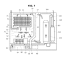
FIG. 6, as a perspective view illustrating an inside the cooling space provided at a ceiling of the refrigerator of FIG. 1, is the perspective view illustrating the refrigerator after removing an upper wall, FIG. 7 is a plane view illustrating an inside the cooling space provided at the ceiling of the refrigerator of FIG. 1, and FIG. 8 is a cross-sectional view illustrating an enlarged view of the evaporator of the refrigerator of FIG. 1.
Referring to FIG. 6 to FIG. 8, the evaporator 70 may be a pin-tube type heat-exchanging apparatus having a heat-exchanging tube 71 to heat-exchange with the surrounding air while a refrigerant is provided to flow, and a heat-exchanging pin 72 to expand a heat-transferring area while making contact with the heat-exchanging tube 71. The each heat-exchanging pin 72 may be disposed in forward/backward directions with respect to each other not to interrupt the flow of air. The heat-exchanging tube 71 may be provided to penetrate the heat-exchanging pin 72. The heat-exchanging tube 71 may be provided with the shape of a zigzag pattern.
The evaporator 70 may be provided with a refrigerant inlet pipe 73 such that a refrigerant is inlet into the heat-exchanging tube 71 through the refrigerant inlet pipe 73, and a refrigerant outlet pipe 75 such that the refrigerant of the heat-exchanging tube 71 is discharged through the refrigerant outlet pipe 75. The refrigerant pipe 26 may be connected to the each of the refrigerant inlet pipe 73 and the refrigerant outlet pipe 75. The refrigerant pipe 26 is penetrated through the rear wall 16 of the body 10, and may be extended to the cooling space 60 along the side wall 17 of the body 10.
The refrigerant inlet pipe 73 of the evaporator 70, as well as the refrigerant outlet pipe 75, may be positioned at a front of the evaporator 70. Therefore, the connecting task of the refrigerant inlet pipe 73 and the refrigerant outlet pipe 75, as well as the connecting task of the refrigerant outlet pipe 75 and the refrigerant pipe 26, may be taken place at a front of the evaporator 70. That is, a connecting unit 74 of the refrigerant pipe 26 and the refrigerant inlet pipe 73, as well as a connecting unit 76 of the refrigerant pipe 26 and the refrigerant outlet pipe 75, may be positioned at a front of the evaporator 70. By the structure as such, a convenience of an assembly may be improved.
A defrosting heater 77 configured to radiate heat to remove frost, which is formed at a surface of the evaporator 70 due to the difference of temperature, may be provided at the surroundings of the evaporator 70. The defrosting heater 77 may be provided in the form of a code heater. The defrosting heater 77 may be disposed below the evaporator 70 in the shape of a zigzag pattern to correspond to the area of the evaporator 70.
A drain plate 78 configured to gather defrost water, which is formed as frost is melted, may be provided below the evaporator 70. The drain plate 78 may be downwardly inclined toward the rear wall 16 of the body 10 to guide the gathered defrost water toward the rear wall 16 of the body 10. The drain plate 78 may be connected to a hose 79 configured to guide the gathered defrost water to the machinery compartment 24 or to an outside the body 10. The drain hose 79 may be provided to penetrate the rear wall 16 of the body 10.
The blower fan 61 configured to increase heat-exchanging efficiency of the evaporator 70 by forcedly flowing air and to circulate cool air may be provided at the cooling space 60. The blower fan 61 may be provided at a front of the evaporator 70. Therefore, the blower fan 61 is provided to inlet air from a rear of the evaporator 70, heat-exchange the inlet air by having the inlet air pass through the evaporator 70, and forcedly flow the air cooled through the evaporator 70 toward a front of the evaporator 70.
The refrigerator 1 may further include an ice maker 80 to generate ice. The ice maker 80 may include an ice-making cell 81 configured to accommodate water and generate ice while provided with the approximate shape of a semicircle, a scraper 83 rotatably provided to move the ice generated at the ice-making cell 81 from the ice-making cell 81, a driving unit 82 having a motor configured to provide a driving force to rotate the scraper 83, and a slider 84 inclinedly formed to descend the ice moved from the ice-making cell 83 to the ice bucket 90 provided at the door 30.
In the present embodiment, the ice maker 80 may be provided at a front of the evaporator 70. Therefore, the cool air generated at the evaporator 70 is provided to flow toward the ice maker 80 by the blower fan 61, and ice may be generated at the ice maker 80 by the cool air as such. However, differently from the present embodiment, the ice maker 80 may be provided in the form of a direct-cooling type ice maker configured to be delivered with cooling energy as a direct contact is made with the refrigerant pipe 26.
In a case when the height of the ice maker 80 is large enough not to be completely accommodated at the cooling space 60, the upper wall 14 of the body 10 may be partially provided with an open portion thereof to accommodate the ice maker 80. An upper cover 19 (FIG. 2) may be coupled to the open portion, or the upper wall 14 of the body 10 may be provided to be protruded in some degree toward an upper side.
As described above, the ice passing unit 64 may be formed at the cover plate 50 so that the ice moved from the ice maker 80 may be descended to the ice bucket 90 provided at the door 30. An ice inlet unit 93 may be formed at an upper end of the ice bucket 90 at a position corresponding to the ice passing unit 64 of the cover plate 50.
In addition, the ice bucket cool air supplying hole 62 is formed at the cover plate 50 to cool the ice stored at the ice bucket 90 by supplying the cool air of the cooling space 60 at the ice bucket 90, and a cool air inlet 91 may be formed at the ice bucket 90 at a position corresponding to the ice bucket cool air supplying hole 62.
That is, the cool air of the cooling space 60 may be supplied to an inside the ice bucket 90 through the ice bucket cool air supplying hole 62 of the cover plate 50 and the cool air inlet 91 of the ice bucket 90. The ice bucket cool air supplying hole 62 may be formed at a front of the evaporator 70.
A cool air collecting duct 57 may be provided at the cover plate 50 to collect the cool air heated at the ice bucket 90 to the cooling space 60. The cool air collecting duct 57 may be integrally formed with the cover plate 50 at an upper surface of the cover plate 50. Therefore, the cool air collecting duct 57 need not take over the space of the storage compartment 21 without being exposed at the storage compartment 21. However, differently from the present embodiment, the cool air collecting duct 57 may be provided separately from the cover plate 50, or may be provided at a lower surface of the cover plate 50.
An entry 58 of the cool air collecting duct 57 may be provided at a front of the evaporator 70, and an exit 59 of the cool air collecting duct 57 may be provided at a rear of the evaporator 70. A cool air outlet 92 may be provided at the ice bucket 90 at a position corresponding to the entry 58 of the cool air collecting duct 57.
Therefore, the cool air heated at the ice bucket 90 may be collected to the cooling space 60 after passing through the cool air outlet 92 of the ice bucket 90, as well as through the cool air collecting duct 57 of the cover plate 50.
In the present embodiment, the cool air inlet 91 of the ice bucket 90 is integrally formed with the ice inlet unit 93 of the ice bucket 90, but is not limited hereto, and the cool air inlet 92 and the ice inlet unit 93 may be separately formed.
The ice bucket 90 may be provided with the stirrer 96 to stir ice so that the ice stored at the ice bucket 90 may be easily outlet through the outlet 95 at a lower end of the ice bucket 90, and a passive coupler 98 to deliver a rotational force at the stirrer 96 while connected to the stirrer 96.
The cooling space 60 may be provided with a stirring motor 99 to generate a rotational force to rotate the stirrer 96, and a driving coupler 97 rotated by receiving a driving force from the stirring motor 99 and coupled to the passive coupler 98. The stirring motor 99 and the driving coupler 97 may be connected by a decelerating connection unit (not shown).
The driving coupler 97 and the passive coupler 98 may receive a driving force by reciprocally coupled to each other when the door 30 is closed, and when the door 30 is open, the driving coupler 97 and the passive coupler 98 may be reciprocally separated from each other. As set forth above, as the stirring motor 99 is provided at the cooling space 60 of the body 10, the structure of the ice bucket 90 is simplified, and an ice storage space of an inside the ice bucket 90 may be expanded.
The ice bucket 90 may be provided with the cool air inlet 91, as well as a sealing member 94 closely attached to the cover plate 50 to seal the cool air outlet 92. The sealing member 94 may be formed of a rubber material. The sealing member 94 may be formed to wrap around the all of the cool air inlet 91, the cool air outlet 92, and the ice inlet unit 93. The sealing member 94 may be closely attached to the front inclination unit 61 of the cover plate 50.
However, in contrast to the above example, the sealing member may be provided at the cover plate 50.
The cooling space 60 may be provided with a water supplying system 100 to supply water to the ice maker 90 or to supply water to the dispenser 34 of the door 30. That is, a side of one side wall of the cooling space 60 may be provided with the evaporator 70, the blower fan 61, and the ice maker 80, and a side of an opposite side wall of the cooling space 60 may be provided with the water supplying system 100.
The water supplying system 100 may include a filter 101 to filter the water supplied from an outside water supplying source, a water tank 102 to cool water by use of the cool air of the cooling space 60, a valve 103 to divide the water supplied from the outside water supplying source into the water tank 102 and the ice maker 80, and a water supplying hose 104 to connect the filter 101, the water tank 102, the valve 103, and the ice maker 80.
The filter 101 may be detachably coupled to a connector 105 into which the water supplying hose 104 is coupled. The cover plate 50 may be provided with a filter mounting hole 54 capable of mounting and dismounting the filter 101 at the connector 105, and a filter cover 55 may be coupled to the filter mounting hole 54 to open or close the filter mounting hole 54. The filter cover 55 may be rotatably provided while having the hinge axis 56 as a center.
The valve 103 is connected to an end portion of an exit of the filter 101, and may divide the water filtered at the filter 101 into the water tank 102 and the ice maker 80. Therefore, the valve 103 may be provided in the form of a 3-way flow path converting valve.
The water tank 102 is disposed at the cooling space 60, and thus may be cooled by the cool air circulated at the cooling space 60 without a separate duct structure. The water cooled at the water tank 102 may be supplied to the dispenser 34 of the door 30 through the water supplying hose 104. The water supplying hose 104 connecting the water tank 102 to the dispenser 34 may be connected to the dispenser 34 of the door 30 through a hinge unit of the door 30.
With the structure above, the evaporator 70 to generate cool air, the ice maker 80 to generate ice, and the water supplying system 100 to supply water are all provided at the cooling space 60 provided at the ceiling of the refrigerator, and thus the rear wall 16 of the body 10 of the refrigerator may be evenly leveled, and the usefulness of space may be increased.
An operation of the refrigerator in accordance with the embodiment of the present disclosure will be briefly described. When the blower fan 61 disposed at the cooling space 60 is driven, the air of the storage compartment 21 is inlet into the cooling space 60 through the cool air collecting hole 53 of the cover plate 50. In addition, the air of the ice bucket 90 is inlet into the cooling space 60 through the cool air collecting duct 57.
The inlet air is cooled through the evaporator 70, and the cooled air is discharged toward a front of the evaporator 70. A portion of the cooled air is provided to cool the ice maker 80 and the water supplying system 100 while circulating at an inside of the cooling space 60, the other portion of the cooled air is provided to cool an inside of the storage compartment 21 while being supplied to the storage compartment 21 through the cool air supplying hole 52 of the cover plate 50, and the remaining portion of the cooled air is provided to cool an inside of the ice bucket 90 while being supplied to the ice bucket 90 through the ice bucket cool air supplying hole 62 of the cover plate 50.
From the above, the embodiment having the cooling space 60 formed at the ceiling of the body 10 of the refrigerator and provided with the all of the evaporator 70, the ice maker 80, and the water supplying system 100 included at the cooling space 60 is described, but the present embodiment is provided as one example for the convenience of description, and the aspect of the present disclosure is not limited to the present embodiment.
As is apparent from the above, in accordance with an aspect of the present disclosure, as an evaporator is disposed at a ceiling of a refrigerator, a rear wall of a storage compartment of the refrigerator may be evenly leveled and usefulness of space may be increased.
In accordance with another aspect of the present disclosure, as an evaporator and a water supplying system are simultaneously disposed at a cooling space provided at a ceiling of a refrigerator, no separate space is needed to be provided for the water supplying system, and the cool air generated at the evaporator may directly cool the water supplying system.
In accordance with still another aspect of the present disclosure, an evaporator is provided at a ceiling of a refrigerator, and the cool air generated at the evaporator may cool a storage compartment and an ice bucket of a door together.
Although a few embodiments of the present disclosure have been shown and described, it would be appreciated by those skilled in the art that changes may be made in these embodiments without departing from the principles and spirit of the disclosure, the scope of which is defined in the claims and their equivalents.
As one example, even when any particular one of the ice maker 80, the water supplying system 100, and the ice bucket 90 is not included, any embodiment provided with a structure of the cooling space 60 compartmented and formed by the cover plate 50 at the ceiling of the body 10 of the refrigerator, the evaporator 70 provided at the cooling space 60, and the cool air generated at the evaporator 70 circulated at the cooling space 60 and the storage compartment 21 through the cool air supplying hole 52 and the cool air collecting hole 53 of the cover plate 50 may be included in the aspect of the present disclosure.

Claims (25)

What is claimed is:
1. A refrigerator, comprising:
a body having a storage compartment;
a door configured to open and to close the storage compartment;
a cover plate disposed at an inside of the storage compartment;
a cooling space formed in the body between the cover plate and a ceiling of the body;
a motor in the cooling space;
an evaporator disposed at an inside of the cooling space and configured to generate cool air;
a blower fan disposed at the inside of the cooling space and configured to forcedly circulate the cool air generated by the evaporator;
an ice maker disposed at the inside of the cooling space and configured to generate ice;
an ice bucket disposed at the door and configured to store the ice generated by the ice maker at the inside of the cooling space, the ice bucket including a stirrer couplable to the motor in the cooling space and configured to stir the ice stored in the ice bucket;
a cool air supplying hole formed in the cover plate and configured to supply the cool air of the cooling space to the storage compartment; and
a cool air collecting hole formed at the cover plate and configured to collect the cool air heated at the storage compartment to the cooling space.
2. The refrigerator of claim 1, wherein:
the cool air supplying hole is provided at a front of the evaporator.
3. The refrigerator of claim 1, wherein:
the cool air collecting hole is provided at a rear of the evaporator.
4. The refrigerator of claim 1, wherein:
the ice maker is provided at a front of the evaporator.
5. The refrigerator of claim 1, further comprising:
an ice bucket cooling air supplying hole formed at the cover plate to supply the cool air of the cooling space to the ice bucket.
6. The refrigerator of claim 5, wherein:
the ice bucket cooling air supplying hole is provided at the front of the evaporator.
7. The refrigerator of claim 1, further comprising:
a cool air collecting duct configured to communicate the cooling space with the ice bucket to collect the cool air heated at the ice bucket to the cooling space.
8. The refrigerator of claim 7, wherein:
an entry of the cool air collecting duct is provided at the front of the evaporator, and an exit of the cool air collecting duct is provided at a rear of the evaporator.
9. The refrigerator of claim 1, further comprising:
a defrosting heater provided near the evaporator in the cooling space and configured to remove frost generated at the evaporator.
10. The refrigerator of claim 1, further comprising:
a drain plate provided below the evaporator in the cooling space and configured to collect defrost water generated at the evaporator.
11. The refrigerator of claim 10, wherein:
the drain plate is downwardly inclined toward a rear wall of the body and configured to guide the collected defrost water toward the rear wall of the body.
12. The refrigerator of claim 1, wherein:
a refrigerant inlet pipe of the evaporator and a refrigerant outlet pipe of the evaporator each are positioned at a front of the evaporator.
13. The refrigerator of claim 4, further comprising:
a water supplying system provided at the cooling space to supply water to the ice maker or to supply water to a dispenser of the door.
14. The refrigerator of claim 13, wherein:
the water supplying system comprises a filter configured to filter the water supplied from an outside water supplying source.
15. The refrigerator of claim 13, wherein:
the water supplying system comprises a water tank configured to cool water by cool air of the cooling space.
16. The refrigerator of claim 15, wherein:
the water supplying system comprises a valve configured to divide the water supplied from the outside water supplying source to the water tank and the ice maker.
17. A refrigerator, comprising:
a body having a storage compartment;
a door configured to open and to close the storage compartment;
a cover plate disposed at an inside of the storage compartment;
a cooling space formed in the body between the cover plate and a ceiling of the body;
an evaporator disposed at an inside of the cooling space and configured to generate cool air;
a blower fan disposed at the inside of the cooling space and configured to forcedly circulate the cool air generated by the evaporator;
an ice maker disposed at the inside of the cooling space at a front of the evaporator and configured to generate ice;
an ice bucket disposed at the door and configured to store the ice generated by the ice maker at the inside of the cooling space;
a cool air supplying hole formed in the cover plate and configured to supply the cool air of the cooling space to the storage compartment;
a cool air collecting hole formed at the cover plate and configured to collect the cool air heated at the storage compartment to the cooling space; and
a water supplying system provided at the cooling space and configured to supply water to the ice maker or to supply water to a dispenser of the door and including a filter configured to filter the water supplied from an outside water supplying source,
wherein the filter is mountably and detachably provided through the cover plate.
18. The refrigerator of claim 17, wherein:
the cover plate comprises a filter mounting hole to mount and dismount the filter therethrough, and a filter cover configured to open or to close the filter mounting hole.
19. A refrigerator, comprising:
a body having a storage compartment;
a door configured to open and to close the storage compartment;
a cover plate disposed at an inside of the storage compartment;
a cooling space formed in between the cover plate and a ceiling of the body;
a motor in the cooling space;
an evaporator disposed at an inside of the cooling space and configured to generate cool air;
a blower fan disposed at the inside of the cooling space and configured to forcedly circulate the cool air generated at the evaporator;
an ice maker disposed at the inside of the cooling space and configured to generate ice;
an ice bucket disposed at the door to store the ice generated by the ice maker at the inside of the cooling space, the ice bucket including a stirrer couplable to the motor in the cooling space and configured to stir the ice stored in the ice bucket; and
a water supplying system disposed at the inside of the cooling space and configured to supply water to the ice maker or to supply water to a dispenser of the door.
20. The refrigerator of claim 19, wherein:
a portion of the cool air of the cooling space cools the water supplying system of the cooling space while circulating inside the cooling space, and the remaining portion of the cool air of the cooling space is collected to the cooling space after cooling the storage compartment while supplied to the storage compartment.
21. The refrigerator of claim 20, wherein:
a portion of the cool air of the cooling space cools the water supplying system of the cooling space while circulating inside the cooling space, another portion of the cool air of the cooling space is collected to the cooling space after cooling the storage compartment while supplied to the storage compartment, and the remaining portion of the cool air of the cooling space is collected to the cooling space after cooling the ice bucket while supplied to the ice bucket.
22. A refrigerator, comprising:
a body having a storage compartment;
a door configured to open and to close the storage compartment;
a cover plate disposed at an inside of the storage compartment;
a cooling space formed in between the cover plate and a ceiling of the body;
a motor in the cooling space;
an evaporator disposed at an inside of the cooling space and configured to generate cool air;
a blower fan disposed at the inside of the cooling space and configured to forcedly circulate the cool air generated at the evaporator;
an ice maker disposed at the inside of the cooling space and configured to generate ice; and
an ice-bucket disposed at the door and configured to store the ice generated by the ice maker at the inside of the cooling space, the ice bucket including a stirrer couplable to the motor in the cooling space and configured to stir the ice stored in the ice bucket.
23. The refrigerator of claim 22, wherein:
a portion of the cool air of the cooling space is collected to the cooling space after cooling the storage compartment while supplied to the storage compartment, and the remaining portion of the cool air of the cooling space is collected to the cooling space after cooling the ice bucket while supplied to the ice bucket.
24. The refrigerator of claim 22, further comprising:
a water supplying system provided at the cooling space to supply water to the ice maker or to supply water to a dispenser of the door.
25. The refrigerator of claim 24, wherein:
a portion of the cool air of the cooling space cools the water supplying system of the cooling space while circulating inside the cooling space, another portion of the cool air of the cooling space is collected to the cooling space after cooling the storage compartment while supplied to the storage compartment, and the remaining portion of the cool air of the cooling space is collected to the cooling space after cooling the ice bucket while supplied to the ice bucket.
US14/803,248 2014-08-18 2015-07-20 Refrigerator Active 2036-03-27 US10072888B2 (en)

Applications Claiming Priority (2)

Application Number Priority Date Filing Date Title
KR10-2014-0107005 2014-08-18
KR1020140107005A KR102236751B1 (en) 2014-08-18 2014-08-18 Refrigerator

Publications (2)

Publication Number Publication Date
US20160047591A1 US20160047591A1 (en) 2016-02-18
US10072888B2 true US10072888B2 (en) 2018-09-11

Family

ID=53783643

Family Applications (1)

Application Number Title Priority Date Filing Date
US14/803,248 Active 2036-03-27 US10072888B2 (en) 2014-08-18 2015-07-20 Refrigerator

Country Status (4)

Country Link
US (1) US10072888B2 (en)
EP (1) EP2988078B1 (en)
KR (1) KR102236751B1 (en)
CN (1) CN105371550A (en)

Cited By (8)

* Cited by examiner, † Cited by third party
Publication number Priority date Publication date Assignee Title
US20180128530A1 (en) * 2016-11-10 2018-05-10 Haier Us Appliance Solutions, Inc. Refrigerator appliance and ice-making assembly therefor
US10274237B2 (en) 2017-01-31 2019-04-30 Haier Us Appliance Solutions, Inc. Ice maker for an appliance
US10391430B2 (en) 2015-09-21 2019-08-27 Haier Us Appliance Solutions, Inc. Filter assembly
US10502477B2 (en) 2014-07-28 2019-12-10 Haier Us Appliance Solutions, Inc. Refrigerator appliance
US10571179B2 (en) 2017-01-26 2020-02-25 Haier Us Appliance Solutions, Inc. Refrigerator appliance with a clear icemaker
US10605493B2 (en) 2017-01-26 2020-03-31 Haier Us Appliance Solutions, Inc. Refrigerator appliance with a clear icemaker
US10775087B2 (en) 2013-10-16 2020-09-15 Samsung Electronics Co., Ltd. Ice-making tray and refrigerator comprising same
US11828526B2 (en) 2018-03-12 2023-11-28 Whirlpool Corporation Anti-rolling icebox gasket for refrigerator swing doors

Families Citing this family (17)

* Cited by examiner, † Cited by third party
Publication number Priority date Publication date Assignee Title
US10119742B2 (en) * 2012-05-18 2018-11-06 Whirlpool Corporation Flat top modular cooling system ice and air delivery
CN106225387B (en) * 2016-07-20 2019-03-12 青岛海尔股份有限公司 Refrigerator
JP2018048798A (en) * 2016-09-16 2018-03-29 東芝ライフスタイル株式会社 refrigerator
KR102632585B1 (en) * 2016-09-29 2024-02-02 엘지전자 주식회사 Refrigerator
KR102882225B1 (en) * 2017-02-21 2025-11-07 엘지전자 주식회사 refrigerator
US10712074B2 (en) 2017-06-30 2020-07-14 Midea Group Co., Ltd. Refrigerator with tandem evaporators
CN108253690A (en) * 2017-12-22 2018-07-06 青岛海尔股份有限公司 Refrigerator
CN108286855A (en) * 2017-12-22 2018-07-17 青岛海尔股份有限公司 Refrigerator
CN108286856A (en) * 2017-12-22 2018-07-17 青岛海尔股份有限公司 Refrigerator
CN108332478A (en) * 2017-12-22 2018-07-27 青岛海尔股份有限公司 Refrigerator
KR102548045B1 (en) 2018-01-26 2023-06-27 엘지전자 주식회사 Ice maker and Refrigerator having the same
US11662138B2 (en) 2018-03-02 2023-05-30 Electrolux Do Brasil S.A. Water circuit assembly for a refrigerator
CN109780776B (en) * 2018-11-20 2021-08-24 海尔智家股份有限公司 Refrigerator and control method thereof
CN111829228B (en) * 2019-04-17 2021-08-31 合肥华凌股份有限公司 Ice storage box and refrigeration equipment
US11009277B2 (en) * 2019-05-15 2021-05-18 Haier Us Appliance Solutions, Inc. Refrigator applicances having a removable ice storage bin
CN114424005A (en) * 2019-09-04 2022-04-29 伊莱克斯巴西有限公司 Apparatus with dual ice maker
CN119042874B (en) * 2024-11-01 2025-02-07 江苏达达节能科技有限公司 Water circulation utilization device with hot water cooling mechanism for ice maker

Citations (16)

* Cited by examiner, † Cited by third party
Publication number Priority date Publication date Assignee Title
JPS509148A (en) 1973-05-30 1975-01-30
US5135645A (en) * 1991-03-28 1992-08-04 Raytheon Company Refrigerator water filter
JPH09105576A (en) 1995-10-06 1997-04-22 Sanyo Electric Co Ltd Defrosting controller for cooler
US20040237565A1 (en) * 2003-05-28 2004-12-02 Lee Myung Ryul Refrigerator with icemaker
EP1621831A1 (en) 2004-07-29 2006-02-01 CANDY S.p.A. Freezer suitable to quickly cool food and refrigerator comprising said freezer
US20060086129A1 (en) 2004-10-26 2006-04-27 Anselmino Jeffery J Ice making and dispensing system
US20090165486A1 (en) * 2006-04-05 2009-07-02 Bsh Bosch Und Siemens Hausgerate Gmbh Refrigeration device comprising a defrost heater
US20100089089A1 (en) 2007-02-06 2010-04-15 Bsh Bosch Und Siemens Hausgerate Gmbh Refrigerating device with circulating air cooling system
US20100126210A1 (en) 2008-11-25 2010-05-27 Whirlpool Corporation Refrigerator with ceiling mounted water system
CN102226620A (en) 2011-05-31 2011-10-26 合肥美的荣事达电冰箱有限公司 Refrigerator
US8132423B2 (en) * 2006-12-01 2012-03-13 Samsung Electronics Co., Ltd. Refrigerator with selective airflow passages between the icemaker and the ice making evaporator
US20120222435A1 (en) 2011-03-02 2012-09-06 Whirlpool Corporation Direct contact icemaker with finned air cooling capacity
US20130098074A1 (en) 2011-10-19 2013-04-25 Thermo Fisher Scientific (Asheville) L.L.C. High performance refrigerator having insulated evaporator cover
EP2664872A2 (en) 2012-05-18 2013-11-20 Whirlpool Corporation Flat top modular cooling system with ice and air delivery
US9097458B2 (en) * 2005-11-30 2015-08-04 BSH Hausgeräte GmbH Refrigeration device comprising a water tank
US9341402B1 (en) * 2012-11-09 2016-05-17 Whirlpool Corporation Refrigerator with vented air flap between icemaking compartment and ice storage area

Family Cites Families (7)

* Cited by examiner, † Cited by third party
Publication number Priority date Publication date Assignee Title
KR100222945B1 (en) * 1997-10-02 1999-10-01 윤종용 Refrigerator having a shelf
JPH11281226A (en) * 1998-03-31 1999-10-15 Sanyo Electric Co Ltd Vertical refrigerator
KR100853423B1 (en) 2007-06-11 2008-08-21 주식회사 대우일렉트로닉스 Refrigerator cooler assembly and refrigerator with same
KR101103031B1 (en) * 2010-07-13 2012-01-05 강연균 Refrigerated Reagent
CN102226617B (en) * 2011-05-31 2013-01-30 合肥美的荣事达电冰箱有限公司 Refrigerator
CN102278848B (en) * 2011-08-30 2016-06-08 海尔集团公司 Refrigerator
KR20140001465A (en) * 2012-06-27 2014-01-07 삼성전자주식회사 Refrigerator

Patent Citations (16)

* Cited by examiner, † Cited by third party
Publication number Priority date Publication date Assignee Title
JPS509148A (en) 1973-05-30 1975-01-30
US5135645A (en) * 1991-03-28 1992-08-04 Raytheon Company Refrigerator water filter
JPH09105576A (en) 1995-10-06 1997-04-22 Sanyo Electric Co Ltd Defrosting controller for cooler
US20040237565A1 (en) * 2003-05-28 2004-12-02 Lee Myung Ryul Refrigerator with icemaker
EP1621831A1 (en) 2004-07-29 2006-02-01 CANDY S.p.A. Freezer suitable to quickly cool food and refrigerator comprising said freezer
US20060086129A1 (en) 2004-10-26 2006-04-27 Anselmino Jeffery J Ice making and dispensing system
US9097458B2 (en) * 2005-11-30 2015-08-04 BSH Hausgeräte GmbH Refrigeration device comprising a water tank
US20090165486A1 (en) * 2006-04-05 2009-07-02 Bsh Bosch Und Siemens Hausgerate Gmbh Refrigeration device comprising a defrost heater
US8132423B2 (en) * 2006-12-01 2012-03-13 Samsung Electronics Co., Ltd. Refrigerator with selective airflow passages between the icemaker and the ice making evaporator
US20100089089A1 (en) 2007-02-06 2010-04-15 Bsh Bosch Und Siemens Hausgerate Gmbh Refrigerating device with circulating air cooling system
US20100126210A1 (en) 2008-11-25 2010-05-27 Whirlpool Corporation Refrigerator with ceiling mounted water system
US20120222435A1 (en) 2011-03-02 2012-09-06 Whirlpool Corporation Direct contact icemaker with finned air cooling capacity
CN102226620A (en) 2011-05-31 2011-10-26 合肥美的荣事达电冰箱有限公司 Refrigerator
US20130098074A1 (en) 2011-10-19 2013-04-25 Thermo Fisher Scientific (Asheville) L.L.C. High performance refrigerator having insulated evaporator cover
EP2664872A2 (en) 2012-05-18 2013-11-20 Whirlpool Corporation Flat top modular cooling system with ice and air delivery
US9341402B1 (en) * 2012-11-09 2016-05-17 Whirlpool Corporation Refrigerator with vented air flap between icemaking compartment and ice storage area

Non-Patent Citations (3)

* Cited by examiner, † Cited by third party
Title
European Office Action dated Jan. 23, 2018 in European Patent Application No. 15180241.0.
European Office Action dated Jun. 14, 2017 in corresponding European Patent Application No. 15 180 241.0.
Extended European Search Report dated Dec. 22, 2015 in European Patent Application 15180241.0.

Cited By (9)

* Cited by examiner, † Cited by third party
Publication number Priority date Publication date Assignee Title
US10775087B2 (en) 2013-10-16 2020-09-15 Samsung Electronics Co., Ltd. Ice-making tray and refrigerator comprising same
USRE50302E1 (en) 2013-10-16 2025-02-18 Samsung Electronics Co., Ltd. Ice-making tray and refrigerator comprising same
US10502477B2 (en) 2014-07-28 2019-12-10 Haier Us Appliance Solutions, Inc. Refrigerator appliance
US10391430B2 (en) 2015-09-21 2019-08-27 Haier Us Appliance Solutions, Inc. Filter assembly
US20180128530A1 (en) * 2016-11-10 2018-05-10 Haier Us Appliance Solutions, Inc. Refrigerator appliance and ice-making assembly therefor
US10571179B2 (en) 2017-01-26 2020-02-25 Haier Us Appliance Solutions, Inc. Refrigerator appliance with a clear icemaker
US10605493B2 (en) 2017-01-26 2020-03-31 Haier Us Appliance Solutions, Inc. Refrigerator appliance with a clear icemaker
US10274237B2 (en) 2017-01-31 2019-04-30 Haier Us Appliance Solutions, Inc. Ice maker for an appliance
US11828526B2 (en) 2018-03-12 2023-11-28 Whirlpool Corporation Anti-rolling icebox gasket for refrigerator swing doors

Also Published As

Publication number Publication date
US20160047591A1 (en) 2016-02-18
EP2988078A1 (en) 2016-02-24
KR102236751B1 (en) 2021-04-06
CN105371550A (en) 2016-03-02
KR20160021570A (en) 2016-02-26
EP2988078B1 (en) 2020-09-30

Similar Documents

Publication Publication Date Title
US10072888B2 (en) Refrigerator
US11378322B2 (en) Ice storage apparatus and method of use
US9080799B2 (en) Refrigerator
US10634408B2 (en) Refrigerator having a rotatable door for the ice making compartment forming the exterior appearance
US8973391B2 (en) Refrigerator
JP5744808B2 (en) refrigerator
US9074804B2 (en) Refrigerator
US10119740B2 (en) Refrigerator
EP2282145A2 (en) Ice-making unit and refrigerator having the same
KR20130114850A (en) Refrigerator and manufacturing method thereof
KR20100138108A (en) Ice maker and refrigerator having same
JP2013064591A (en) Refrigerator
EP2097689A1 (en) Ice making system and method for ice making of refrigerator
US20190331395A1 (en) Ice Maker and Refrigerator Having Same
KR100846890B1 (en) Ice Making System and Ice Making Method
KR102753109B1 (en) Refrigerator
CN116685818A (en) refrigerator
KR20080061179A (en) Ice making device and ice making method

Legal Events

Date Code Title Description
AS Assignment

Owner name: SAMSUNG ELECTRONICS CO., LTD., KOREA, REPUBLIC OF

Free format text: ASSIGNMENT OF ASSIGNORS INTEREST;ASSIGNORS:JEONG, JIN;SON, BONG SU;JANG, DO YUN;AND OTHERS;SIGNING DATES FROM 20150717 TO 20150720;REEL/FRAME:036134/0073

STCF Information on status: patent grant

Free format text: PATENTED CASE

MAFP Maintenance fee payment

Free format text: PAYMENT OF MAINTENANCE FEE, 4TH YEAR, LARGE ENTITY (ORIGINAL EVENT CODE: M1551); ENTITY STATUS OF PATENT OWNER: LARGE ENTITY

Year of fee payment: 4