US10072678B2 - Regeneration deactivation valve and method - Google Patents
Regeneration deactivation valve and method Download PDFInfo
- Publication number
- US10072678B2 US10072678B2 US14/747,498 US201514747498A US10072678B2 US 10072678 B2 US10072678 B2 US 10072678B2 US 201514747498 A US201514747498 A US 201514747498A US 10072678 B2 US10072678 B2 US 10072678B2
- Authority
- US
- United States
- Prior art keywords
- workport
- control valve
- node
- regeneration
- flow control
- Prior art date
- Legal status (The legal status is an assumption and is not a legal conclusion. Google has not performed a legal analysis and makes no representation as to the accuracy of the status listed.)
- Active, expires
Links
Images


Classifications
-
- F—MECHANICAL ENGINEERING; LIGHTING; HEATING; WEAPONS; BLASTING
- F15—FLUID-PRESSURE ACTUATORS; HYDRAULICS OR PNEUMATICS IN GENERAL
- F15B—SYSTEMS ACTING BY MEANS OF FLUIDS IN GENERAL; FLUID-PRESSURE ACTUATORS, e.g. SERVOMOTORS; DETAILS OF FLUID-PRESSURE SYSTEMS, NOT OTHERWISE PROVIDED FOR
- F15B11/00—Servomotor systems without provision for follow-up action; Circuits therefor
- F15B11/02—Systems essentially incorporating special features for controlling the speed or actuating force of an output member
- F15B11/024—Systems essentially incorporating special features for controlling the speed or actuating force of an output member by means of differential connection of the servomotor lines, e.g. regenerative circuits
-
- F—MECHANICAL ENGINEERING; LIGHTING; HEATING; WEAPONS; BLASTING
- F15—FLUID-PRESSURE ACTUATORS; HYDRAULICS OR PNEUMATICS IN GENERAL
- F15B—SYSTEMS ACTING BY MEANS OF FLUIDS IN GENERAL; FLUID-PRESSURE ACTUATORS, e.g. SERVOMOTORS; DETAILS OF FLUID-PRESSURE SYSTEMS, NOT OTHERWISE PROVIDED FOR
- F15B13/00—Details of servomotor systems ; Valves for servomotor systems
- F15B13/02—Fluid distribution or supply devices characterised by their adaptation to the control of servomotors
- F15B13/04—Fluid distribution or supply devices characterised by their adaptation to the control of servomotors for use with a single servomotor
- F15B13/0401—Valve members; Fluid interconnections therefor
- F15B13/0402—Valve members; Fluid interconnections therefor for linearly sliding valves, e.g. spool valves
- F15B13/0403—Valve members; Fluid interconnections therefor for linearly sliding valves, e.g. spool valves a secondary valve member sliding within the main spool, e.g. for regeneration flow
-
- F—MECHANICAL ENGINEERING; LIGHTING; HEATING; WEAPONS; BLASTING
- F15—FLUID-PRESSURE ACTUATORS; HYDRAULICS OR PNEUMATICS IN GENERAL
- F15B—SYSTEMS ACTING BY MEANS OF FLUIDS IN GENERAL; FLUID-PRESSURE ACTUATORS, e.g. SERVOMOTORS; DETAILS OF FLUID-PRESSURE SYSTEMS, NOT OTHERWISE PROVIDED FOR
- F15B11/00—Servomotor systems without provision for follow-up action; Circuits therefor
- F15B11/02—Systems essentially incorporating special features for controlling the speed or actuating force of an output member
- F15B11/024—Systems essentially incorporating special features for controlling the speed or actuating force of an output member by means of differential connection of the servomotor lines, e.g. regenerative circuits
- F15B2011/0243—Systems essentially incorporating special features for controlling the speed or actuating force of an output member by means of differential connection of the servomotor lines, e.g. regenerative circuits the regenerative circuit being activated or deactivated automatically
-
- F—MECHANICAL ENGINEERING; LIGHTING; HEATING; WEAPONS; BLASTING
- F15—FLUID-PRESSURE ACTUATORS; HYDRAULICS OR PNEUMATICS IN GENERAL
- F15B—SYSTEMS ACTING BY MEANS OF FLUIDS IN GENERAL; FLUID-PRESSURE ACTUATORS, e.g. SERVOMOTORS; DETAILS OF FLUID-PRESSURE SYSTEMS, NOT OTHERWISE PROVIDED FOR
- F15B2211/00—Circuits for servomotor systems
- F15B2211/50—Pressure control
- F15B2211/505—Pressure control characterised by the type of pressure control means
- F15B2211/50563—Pressure control characterised by the type of pressure control means the pressure control means controlling a differential pressure
-
- Y—GENERAL TAGGING OF NEW TECHNOLOGICAL DEVELOPMENTS; GENERAL TAGGING OF CROSS-SECTIONAL TECHNOLOGIES SPANNING OVER SEVERAL SECTIONS OF THE IPC; TECHNICAL SUBJECTS COVERED BY FORMER USPC CROSS-REFERENCE ART COLLECTIONS [XRACs] AND DIGESTS
- Y10—TECHNICAL SUBJECTS COVERED BY FORMER USPC
- Y10T—TECHNICAL SUBJECTS COVERED BY FORMER US CLASSIFICATION
- Y10T137/00—Fluid handling
- Y10T137/7722—Line condition change responsive valves
- Y10T137/7837—Direct response valves [i.e., check valve type]
- Y10T137/7838—Plural
- Y10T137/7842—Diverse types
-
- Y—GENERAL TAGGING OF NEW TECHNOLOGICAL DEVELOPMENTS; GENERAL TAGGING OF CROSS-SECTIONAL TECHNOLOGIES SPANNING OVER SEVERAL SECTIONS OF THE IPC; TECHNICAL SUBJECTS COVERED BY FORMER USPC CROSS-REFERENCE ART COLLECTIONS [XRACs] AND DIGESTS
- Y10—TECHNICAL SUBJECTS COVERED BY FORMER USPC
- Y10T—TECHNICAL SUBJECTS COVERED BY FORMER US CLASSIFICATION
- Y10T137/00—Fluid handling
- Y10T137/8593—Systems
- Y10T137/86493—Multi-way valve unit
Definitions
- the present invention relates to hydraulic systems that control operation of a hydraulic cylinder, and more particularly to a valve arrangement and method incorporating a regeneration function for controlling operation of such a hydraulic cylinder.
- controllability and efficiency are several metrics that can be used to quantify the profitability and operator “feel” of the machine.
- Cavitation is an unwanted condition that can occur when a function has an overrunning load.
- the hydraulic cylinder used to control the excavator arm is susceptible to cavitation due to the arm having a large amount of potential energy when it is fully out, and the cylinder has a rather large cylinder area to fill with hydraulic fluid as the arm comes in towards the excavator.
- One method to keep the arm from cavitating is to use regeneration of the arm cylinder where some of the rod exhaust fluid is pushed back into the head of the cylinder to help makeup (regenerate) fluid as the head chamber is expanding. This requires a connection from the rod side of the cylinder to the head side of the cylinder and normally a smaller connection from the rod side of the cylinder to the tank.
- the head side of the cylinder can have a higher pressure then the rod side of the cylinder, which does not allow for regeneration. Therefore, all of the rod fluid must go to tank through the smaller rod side to tank connection. This causes a large differential pressure across the control valve, which results in a high rod side pressure. This rod side pressure works against the head side pressure when digging, which reduces the force and efficiency of the machine.
- Hydraulic circuits have attempted to better control the regeneration function by sensing pressure at the fluid source to determine if regeneration should occur. Based on the sensed pressure at the fluid source, the circuit can open a secondary passage to reduce the differential pressure across the control valve. Yet, these circuits still fail to provide better control for regenerating as the sensed pressure at the fluid source does not always provide the appropriate pressure value for determining when regeneration should occur.
- a regeneration deactivation valve can “sense,” i.e., react to a differential pressure, when the function is in free air and the function's cylinder is at risk of cavitating or when then function is doing positive work and the function's cylinder is not at risk of cavitation.
- the regeneration deactivation valve can react to the potential for cavitation by closing, or opening, a fluid path so the cylinder regenerates.
- the regeneration deactivation valve can also react when the cylinder is not at a risk of cavitating and can open up, or close, a fluid path allowing the function to move with more power and efficiency.
- a hydraulic regeneration deactivation valve to deactivate regeneration of a hydraulic cylinder.
- the hydraulic regeneration deactivation valve comprises a body including a tank return node for connection to a tank, a driving workport for connection to a first chamber of the hydraulic cylinder, a return workport for connection to a second chamber of the hydraulic cylinder, the first chamber and the second chamber separated by a piston, and a regeneration node, the regeneration node for connection to the driving workport and for connection to the return workport.
- a flow control valve is received in the body and having a first fluid path between the regeneration node and the tank return node, the first fluid path being substantially unrestricted in a first flow control valve position, and the first fluid path being restricted in a second flow control valve position.
- the flow control valve is responsive to a sense pressure in the driving workport to move between the first flow control valve position and the second flow control valve position.
- a hydraulic control valve comprises a control valve body having a spool bore therein and a node for connection to a fluid source, a tank return node for connection to a tank, a driving workport for connection to a first chamber of the hydraulic cylinder, a return workport for connection to a second chamber of the hydraulic cylinder, the first chamber and the second chamber separated by a piston, and a regeneration node, the regeneration node for connection to the driving workport and for connection to the return workport.
- a spool is slidably received in the spool bore and having a spool first position in which a first fluid path is provided between the node and the driving workport, a spool second position in which a second fluid path is provided between the driving workport and the tank return node, and a spool neutral position in which the driving workport is closed off from both the node and the tank return node.
- a flow control valve is slidably received in the spool bore and having a first fluid path between the regeneration node and the tank return node when the spool is in the spool first position, the first fluid path being substantially unrestricted in a first flow control valve position, and the first fluid path being restricted in a second flow control valve position. And the flow control valve is responsive to a sense pressure in the driving workport to move between the first flow control valve position and the second flow control valve position.
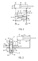
- FIG. 1 illustrates a schematic of a hydraulic circuit including a regeneration deactivation valve according to embodiments of the technology
- FIG. 2 illustrates a schematic of a control valve in a hydraulic circuit, the control valve including a regeneration deactivation valve according to embodiments of the technology
- FIG. 3 depicts a close-up view of the construction of an embodiment of the regeneration deactivation valve as shown in FIG. 2 ;
- FIGS. 4-10 illustrate schematic views of a hydraulic circuit including alternative embodiments of a regeneration deactivation valve according to embodiments of the technology.
- directly connected means that the associated components are connected together by a conduit without any intervening element, such as a valve, an orifice or other device, which restricts or controls the flow of fluid beyond the inherent restriction of any conduit.
- hydraulic cylinder generically refers to a hydraulic actuator that comprises a cylinder body in which a piston moves in response to hydraulic fluid being fed into and drained from the cylinder body and in which a rod is connected to the piston so as the extend from and retract into the cylinder as the piston moves.
- inventive concepts can be described in the context of a hydraulic cylinder usable on heavy machinery such as a front end loader of an excavator, for example, the concepts described herein have broad applicability to controlling a variety of hydraulic devices, such as a hydraulic motor, as a non-limiting example.
- an exemplary embodiment of the technology includes a regeneration deactivation valve 20 connected in a hydraulic circuit including a cylinder 22 , a fluid source 24 , and a tank 26 .
- the cylinder 22 includes an internal bore in which a piston 28 is slidably received, thereby forming a rod chamber 30 and a head chamber 32 within the cylinder 22 on opposite sides of the piston 28 .
- the regeneration deactivation valve 20 includes a flow control valve 48 in a body 49 , the flow control valve 48 able to react to a differential pressure between a sense pressure 31 at supply node 33 , which can be directly connected to the driving workport 34 , and a reference pressure 36 at node 37 , which in some embodiments can be connected or directly connected to a regeneration gallery 38 , to function according to what type of machinery operation is being done.
- the reference pressure 36 can be the same pressure as the return workport 40 or lower, for example. It is to be appreciated that the body 49 is shown generally in relation to the regeneration deactivation valve 20 as the body 49 can take any applicable shape.
- the function can be overrunning, and in the case of an arm on an excavator, for example, the reference pressure 36 , such as at the regeneration gallery 38 , can be at a higher pressure than the sense pressure 31 at the driving workport 34 .
- the regeneration deactivation valve 20 can react to the higher reference pressure 36 by restricting or closing a fluid path including a regeneration node 44 to a tank return node 46 , so the function regenerates by allowing fluid to flow from the rod chamber 30 through the return workport 40 , through a regeneration fluid path 42 , through the driving workport 34 , and to the head chamber 32 .
- the regeneration fluid path 42 can include a check valve 43 to prevent the reverse flow of fluid from the head chamber 32 to the rod chamber 30 .
- the regeneration fluid path can also include a variable orifice 66 to meter the flow from the return workport 40 .
- the regeneration deactivation valve 20 can react to a higher sense pressure 31 at the driving workport 34 than the reference pressure 36 by opening or substantially unrestricting the fluid path including the regeneration node 44 to the tank return node 46 , which allows for a low differential pressure across a restriction 50 (see FIGS. 1 and 3 ) in the regeneration deactivation valve 20 , and creating a low pressure at return workport 40 and an improved efficient dig.
- the flow control valve 48 can include a spring 52 .
- the preload and rate of the spring 52 can be controlled to help bias the regeneration deactivation valve 20 closed and make for a stable transition from open to closed.
- an orifice 54 can be added between regeneration node 44 and the reference pressure 36 at node 37 . This can make for a more stable transition from closed to open or from open to closed.
- orifice 56 (see FIGS. 5 and 8 ) can be added connecting the reference node 37 to the tank return node 46 and creating a pressure divider. In this arrangement, as pressure in the regeneration gallery 38 changes, the reference pressure 36 will follow, but at a lower level based on the relative sizes of orifice 54 and orifice 56 .
- the regeneration deactivation valve 20 is shown incorporated into an exemplary control valve 62 . It is to be appreciated that the regeneration deactivation valve 20 can be a standalone device as shown in FIG. 1 in body 49 , or the regeneration deactivation valve 20 can be integrated with the control valve 62 .
- the control valve 62 is shown including a control valve body 70 having a spool bore 72 , with a spool 74 in the spool bore 72 , and variable orifices 64 , 66 , and 68 on the spool 74 (see FIG. 3 ).
- Variable orifice 64 serves to meter flow from the fluid source 24 to the driving workport 34 .
- Variable orifice 66 serves to meter flow from the return workport 40
- variable orifice 68 serves to meter flow to the tank 26 .
- variable orifices 64 , 66 , and 68 can be included in a hydraulic circuit to control the cylinder 22 , as can be seen in FIG. 1 .
- the tank node 46 may be arranged within the control valve body 70 of the control valve 62 (see, e.g., FIG. 3 ).
- the control valve body 70 can include an inlet 80 , an outlet 82 , a first workport 84 , a second workport 86 , and a regeneration workport 88 .
- the inlet 80 can be in fluid communication with the pump 24 .
- the outlet 82 can be in fluid communication with the tank 26 .
- the first workport 84 and the regeneration workport 88 can be in fluid communication with the head chamber 32
- the second workport 86 can be in fluid communication with the rod chamber 30 .
- the regeneration node 44 can be arranged within the control valve body 70 and can provide fluid communication between the second workport 86 and the regeneration workport 88 .
- the spool 74 can be selectively movable within the spool bore 72 between a spool first position 90 , a spool neutral position 92 , and a spool second position 94 .
- the spool 74 can provide a first metered fluid path between the inlet 80 and the first workport 84 , a second metered fluid path between the second workport 86 and the regeneration workport 88 through the regeneration node 44 , a third metered fluid path between the second workport 86 and the outlet 82 , and a flow control path between the second workport 86 and the outlet 82 arranged in parallel with the third metered fluid path.
- fluid flowing from the rod chamber 30 can either flow from the second workport 86 to the regeneration workport 88 , or from the second workport 86 to the outlet 82 via the third metered fluid path and/or the flow control path, depending on the pressure at the first workport 84 , the position of the flow control valve 48 , and the restriction of the variable orifice 68 .
- fluid flowing from the rod chamber 30 can pass through the regeneration node 44 .
- the regeneration path 42 can be in fluid communication with the regeneration node 44 , and the regeneration path 42 can extend from the regeneration workport 88 to the driving workport 34 and thereby to the head chamber 32 .
- each of the first metered fluid path, the metered second fluid path, and the third metered fluid path can be selectively restricted to provide metering of the fluid flow therealong.
- Metering of the fluid flow along the first fluid path can be provided by the variable orifice 64 .
- Metering of the fluid flow along the second fluid path can be provided by the variable orifice 66 .
- Metering of the fluid flow along the third fluid path can be provided by the variable orifice 68 .
- the driving workport 34 and the return workport 40 are both closed off from all of the supply node 33 , the regeneration node 44 , and the tank return node 46 .
- the spool 74 can provide a fourth fluid path between the inlet 80 and the second workport 86 , a fifth fluid path between the first workport 84 and the outlet 82 , and the second fluid path is closed (i.e., fluid communication is inhibited between the regeneration workport 88 and all of the inlet 80 , the outlet 82 , the first workport 84 , and the second workport 86 ).
- the head chamber 32 can receive pressurized fluid from the pump 24 in the spool first position 90 via the first metered fluid path and the rod chamber 30 can receive pressurize fluid from the pump 24 in the spool second position 94 via the fourth fluid path, the cylinder 22 and the piston 28 can act as a double-acting hydraulic actuator as would be appreciated by one of skill in the art.
- the flow control valve 48 can be arranged on the flow control path within the spool 74 and can be selectively movable between a flow control first position where flow control valve 48 provides a first restriction and a flow control second position where the flow control valve 48 provides a second restriction less than the first restriction.
- the flow control valve 48 can movable between the first flow control position and the second flow control position in response to a pressure at the first workport 84 , which is connected to the driving workport 34 .
- the regeneration deactivation valve 20 is shown in a non-regenerating open position, such that the regeneration gallery 38 is connected to tank 26 (not shown in FIG. 3 ) through the fluid path including the regeneration node 44 to the tank return node 46 .
- FIGS. 4-10 show alternative embodiments of a regeneration deactivation valve connected to a cylinder 22 , a source of fluid 24 , and a tank 26 .
- Each regeneration deactivation valve can be the same as the regeneration deactivation valve 20 , other than restrictive elements can be added to or removed from the hydraulic circuit to influence performance.
- FIG. 4 is similar to FIG. 1 , except orifice 54 has been removed.
- Orifice 54 (without orifice 56 , discussed below) serves as a damping orifice. In other words, it serves to slow down the flow control valve velocity when the valve is transitioning from one position to the next.
- FIG. 5 is similar to FIG. 1 , except orifice 56 has been added.
- the two orifices in series ( 54 and 56 ) set up a flow path from the reference node 37 to the tank return node 46 and create a pressure divider.
- the reference pressure 36 will follow, but at a lower level based on the relative sizes of orifice 54 and orifice 56 .
- FIG. 6 is similar to FIG. 1 , except that the reference node 37 is shown connected to the return workport 40 .
- the reference pressure 36 will be higher than the pressure at the regeneration node 44 , which feeds the regeneration fluid path 42 .
- the flow control valve 48 can sense a pressure differential closer to the pressure differential between the cylinder rod chamber 30 and the head chamber 32 .
- check valve 43 will close preventing regeneration flow, but the regeneration deactivation valve 20 will not shift until a pressure at the return workport 40 becomes higher than a pressure at the driving workport 34 .
- This arrangement can set up a delay in the regeneration deactivation valve shifting that can help stabilize the hydraulic circuit.
- orifice 54 can serve as a damping orifice.
- FIG. 7 is similar to FIG. 6 , except without the damping orifice 54 .
- FIG. 8 is similar to FIG. 5 , except that the reference node 37 is shown connected to the return workport 40 rather than from the regeneration gallery 38 .
- This hydraulic circuit can have the same advantages as the hydraulic circuits of FIGS. 5 and 6 .
- FIG. 9 is similar to FIG. 1 , except the reference pressure 36 is shown connected to the tank return node 46 .
- the regeneration deactivation valve 20 can shift if the force due to the difference between a pressure in the driving work port 34 and the tank return node 46 exceeds the preload on spring 52 .
- FIG. 10 is similar to FIG. 9 , except without the damping orifice 54 .
- the regeneration deactivation valve 20 can be used any time regeneration of a cylinder is possible, including either extension or retraction of the cylinder.
Landscapes
- Engineering & Computer Science (AREA)
- General Engineering & Computer Science (AREA)
- Mechanical Engineering (AREA)
- Physics & Mathematics (AREA)
- Fluid Mechanics (AREA)
- Fluid-Pressure Circuits (AREA)
- Operation Control Of Excavators (AREA)
Abstract
Description
Claims (26)
Priority Applications (1)
| Application Number | Priority Date | Filing Date | Title |
|---|---|---|---|
| US14/747,498 US10072678B2 (en) | 2014-06-23 | 2015-06-23 | Regeneration deactivation valve and method |
Applications Claiming Priority (2)
| Application Number | Priority Date | Filing Date | Title |
|---|---|---|---|
| US201462015620P | 2014-06-23 | 2014-06-23 | |
| US14/747,498 US10072678B2 (en) | 2014-06-23 | 2015-06-23 | Regeneration deactivation valve and method |
Publications (2)
| Publication Number | Publication Date |
|---|---|
| US20150369260A1 US20150369260A1 (en) | 2015-12-24 |
| US10072678B2 true US10072678B2 (en) | 2018-09-11 |
Family
ID=54869262
Family Applications (1)
| Application Number | Title | Priority Date | Filing Date |
|---|---|---|---|
| US14/747,498 Active 2036-07-24 US10072678B2 (en) | 2014-06-23 | 2015-06-23 | Regeneration deactivation valve and method |
Country Status (2)
| Country | Link |
|---|---|
| US (1) | US10072678B2 (en) |
| CN (1) | CN105221504B (en) |
Cited By (2)
| Publication number | Priority date | Publication date | Assignee | Title |
|---|---|---|---|---|
| EP4199701A4 (en) * | 2020-08-20 | 2024-10-16 | Komatsu Forest AB | ADAPTIVE CONTROL OF A HYDRAULIC WOOD HANDLE ON A WOOD HANDLING DEVICE |
| US20250354570A1 (en) * | 2022-06-09 | 2025-11-20 | Hydac Mobilhydraulik Gmbh | Hydraulic System |
Families Citing this family (4)
| Publication number | Priority date | Publication date | Assignee | Title |
|---|---|---|---|---|
| CN106438521A (en) * | 2016-11-11 | 2017-02-22 | 徐工消防安全装备有限公司 | Hydraulic circuit of the differential telescopic system and aerial work platform using hydraulic circuit of the differential telescopic system |
| JP6718370B2 (en) * | 2016-12-22 | 2020-07-08 | 川崎重工業株式会社 | Hydraulic system |
| JP6802766B2 (en) * | 2017-08-03 | 2020-12-23 | 株式会社豊田自動織機 | Hydraulic drive system for industrial vehicles |
| US10816018B2 (en) * | 2017-08-03 | 2020-10-27 | Kabushiki Kaisha Toyota Jidoshokki | Hydraulic driving device of industrial vehicle |
Citations (6)
| Publication number | Priority date | Publication date | Assignee | Title |
|---|---|---|---|---|
| US3267961A (en) * | 1964-04-16 | 1966-08-23 | New York Air Brake Co | Valve |
| US5065664A (en) * | 1989-04-03 | 1991-11-19 | Kabushiki Kaisha Toyoda Jidoshokki Seisakusho | Control circuit for a cylinder allowing flow between an upper and a lower chamber |
| US5479778A (en) * | 1993-12-02 | 1996-01-02 | Hitachi Construction Machinery Co., Ltd. | Hydraulic control system for construction machines |
| US5862831A (en) | 1996-05-21 | 1999-01-26 | Volvo Construction Equipment Korea Co., Ltd. | Variable-regeneration directional control valve for construction vehicles |
| US20040137549A1 (en) | 2000-10-26 | 2004-07-15 | Masanori Sasatsu | Diagnostic and examination method for cancer of the colon using tannase as indication |
| US7337807B2 (en) * | 2004-10-14 | 2008-03-04 | Volvo Construction Equipment Holding Sweden Ab | Hydraulic control valve with regeneration function |
Family Cites Families (5)
| Publication number | Priority date | Publication date | Assignee | Title |
|---|---|---|---|---|
| DK154169C (en) * | 1984-10-03 | 1989-03-20 | Danfoss As | CONTROL DEVICE FOR A HYDRAULIC DRIVE CONSUMER |
| CN201176984Y (en) * | 2008-01-31 | 2009-01-07 | 广东海阳物资回收有限公司 | A regeneration oil device |
| CN201915433U (en) * | 2010-12-09 | 2011-08-03 | 宁波弗莱格液压有限公司 | Hydraulic regeneration system for diggers |
| WO2012091184A1 (en) * | 2010-12-27 | 2012-07-05 | 볼보 컨스트럭션 이큅먼트 에이비 | Energy recycling system for a construction apparatus |
| CN203306927U (en) * | 2013-06-07 | 2013-11-27 | 安徽合力股份有限公司 | Lifting valve bank with flow regeneration function of container face crane |
-
2015
- 2015-06-23 CN CN201510527913.3A patent/CN105221504B/en active Active
- 2015-06-23 US US14/747,498 patent/US10072678B2/en active Active
Patent Citations (6)
| Publication number | Priority date | Publication date | Assignee | Title |
|---|---|---|---|---|
| US3267961A (en) * | 1964-04-16 | 1966-08-23 | New York Air Brake Co | Valve |
| US5065664A (en) * | 1989-04-03 | 1991-11-19 | Kabushiki Kaisha Toyoda Jidoshokki Seisakusho | Control circuit for a cylinder allowing flow between an upper and a lower chamber |
| US5479778A (en) * | 1993-12-02 | 1996-01-02 | Hitachi Construction Machinery Co., Ltd. | Hydraulic control system for construction machines |
| US5862831A (en) | 1996-05-21 | 1999-01-26 | Volvo Construction Equipment Korea Co., Ltd. | Variable-regeneration directional control valve for construction vehicles |
| US20040137549A1 (en) | 2000-10-26 | 2004-07-15 | Masanori Sasatsu | Diagnostic and examination method for cancer of the colon using tannase as indication |
| US7337807B2 (en) * | 2004-10-14 | 2008-03-04 | Volvo Construction Equipment Holding Sweden Ab | Hydraulic control valve with regeneration function |
Cited By (2)
| Publication number | Priority date | Publication date | Assignee | Title |
|---|---|---|---|---|
| EP4199701A4 (en) * | 2020-08-20 | 2024-10-16 | Komatsu Forest AB | ADAPTIVE CONTROL OF A HYDRAULIC WOOD HANDLE ON A WOOD HANDLING DEVICE |
| US20250354570A1 (en) * | 2022-06-09 | 2025-11-20 | Hydac Mobilhydraulik Gmbh | Hydraulic System |
Also Published As
| Publication number | Publication date |
|---|---|
| US20150369260A1 (en) | 2015-12-24 |
| CN105221504B (en) | 2019-06-04 |
| CN105221504A (en) | 2016-01-06 |
Similar Documents
| Publication | Publication Date | Title |
|---|---|---|
| US10072678B2 (en) | Regeneration deactivation valve and method | |
| US9206583B2 (en) | Void protection system | |
| US9587656B2 (en) | Boom driving apparatus for construction machine | |
| CN107044144B (en) | Hydraulic drive device for construction machine | |
| US7204084B2 (en) | Hydraulic system having a pressure compensator | |
| US9261118B2 (en) | Boom cylinder dig flow regeneration | |
| EP3255284B1 (en) | Flow control valve for construction machine | |
| US20080295681A1 (en) | Hydraulic system having an external pressure compensator | |
| US20130086899A1 (en) | Hydraulic system with bi-directional regeneration | |
| US20070044649A1 (en) | Metering valve with integral relief and makeup function | |
| US20110088785A1 (en) | Safety feature for stuck valve | |
| CN107532617B (en) | Flow control valve | |
| US7240604B2 (en) | Electro-hydraulic metering valve with integral flow control | |
| US20170198831A1 (en) | System and method for monitoring performance of relief valves in a hydraulic system | |
| US20140026546A1 (en) | Regeneration Valve for a Hydraulic Circuit | |
| CN106460880B (en) | Fluid pressure control device for construction machine | |
| KR102518559B1 (en) | Valve arrangement for stem cylinder with two operating conditions | |
| JP4493543B2 (en) | Fluid pressure circuit | |
| CN105987035B (en) | Fluid pressure valve device and hydraulic system and machine including the fluid pressure valve device | |
| US20160003267A1 (en) | Electronic Control of Actuator Force and Torque with an Independent Metering Valve | |
| JP6381228B2 (en) | Hydraulic drive | |
| US9644649B2 (en) | Void protection system | |
| EP3138964B1 (en) | Flow control valve for construction equipment | |
| CN113574283B (en) | Regeneration valve for hydraulic circuit | |
| US20160145834A1 (en) | Vent for load sense valves |
Legal Events
| Date | Code | Title | Description |
|---|---|---|---|
| AS | Assignment |
Owner name: HUSCO INTERNATIONAL, INC., WISCONSIN Free format text: ASSIGNMENT OF ASSIGNORS INTEREST;ASSIGNORS:HOLTER, BEN;URBAN, CHRIS;QUINNELL, COREY;REEL/FRAME:036310/0371 Effective date: 20150727 |
|
| STCF | Information on status: patent grant |
Free format text: PATENTED CASE |
|
| AS | Assignment |
Owner name: JPMORGAN CHASE BANK, N.A., WISCONSIN Free format text: SECOND AMENDMENT TO PATENT SECURITY AGREEMENT;ASSIGNOR:HUSCO INTERNATIONAL, INC.;REEL/FRAME:049669/0636 Effective date: 20190628 |
|
| MAFP | Maintenance fee payment |
Free format text: PAYMENT OF MAINTENANCE FEE, 4TH YEAR, LARGE ENTITY (ORIGINAL EVENT CODE: M1551); ENTITY STATUS OF PATENT OWNER: LARGE ENTITY Year of fee payment: 4 |
|
| AS | Assignment |
Owner name: JPMORGAN CHASE BANK, N.A., WISCONSIN Free format text: SECURITY AGREEMENT;ASSIGNOR:HUSCO INTERNATIONAL, INC.;REEL/FRAME:060668/0531 Effective date: 20220615 |
|
| AS | Assignment |
Owner name: HUSCO INTERNATIONAL, INC., WISCONSIN Free format text: RELEASE OF PATENT SECURITY AGMT;ASSIGNOR:JPMORGAN CHASE BANK, N.A.;REEL/FRAME:063575/0962 Effective date: 20220915 |