US10070441B2 - Method and apparatus for generating codeword, and method and apparatus for recovering codeword - Google Patents
Method and apparatus for generating codeword, and method and apparatus for recovering codeword Download PDFInfo
- Publication number
- US10070441B2 US10070441B2 US15/304,844 US201515304844A US10070441B2 US 10070441 B2 US10070441 B2 US 10070441B2 US 201515304844 A US201515304844 A US 201515304844A US 10070441 B2 US10070441 B2 US 10070441B2
- Authority
- US
- United States
- Prior art keywords
- codeword
- punctured
- symbol
- nodes
- symbol nodes
- Prior art date
- Legal status (The legal status is an assumption and is not a legal conclusion. Google has not performed a legal analysis and makes no representation as to the accuracy of the status listed.)
- Active, expires
Links
Images


Classifications
-
- H—ELECTRICITY
- H04—ELECTRIC COMMUNICATION TECHNIQUE
- H04W—WIRELESS COMMUNICATION NETWORKS
- H04W72/00—Local resource management
- H04W72/04—Wireless resource allocation
- H04W72/044—Wireless resource allocation based on the type of the allocated resource
- H04W72/0466—Wireless resource allocation based on the type of the allocated resource the resource being a scrambling code
-
- H—ELECTRICITY
- H03—ELECTRONIC CIRCUITRY
- H03M—CODING; DECODING; CODE CONVERSION IN GENERAL
- H03M13/00—Coding, decoding or code conversion, for error detection or error correction; Coding theory basic assumptions; Coding bounds; Error probability evaluation methods; Channel models; Simulation or testing of codes
- H03M13/63—Joint error correction and other techniques
- H03M13/635—Error control coding in combination with rate matching
- H03M13/6362—Error control coding in combination with rate matching by puncturing
-
- H—ELECTRICITY
- H03—ELECTRONIC CIRCUITRY
- H03M—CODING; DECODING; CODE CONVERSION IN GENERAL
- H03M13/00—Coding, decoding or code conversion, for error detection or error correction; Coding theory basic assumptions; Coding bounds; Error probability evaluation methods; Channel models; Simulation or testing of codes
- H03M13/25—Error detection or forward error correction by signal space coding, i.e. adding redundancy in the signal constellation, e.g. Trellis Coded Modulation [TCM]
- H03M13/255—Error detection or forward error correction by signal space coding, i.e. adding redundancy in the signal constellation, e.g. Trellis Coded Modulation [TCM] with Low Density Parity Check [LDPC] codes
-
- H—ELECTRICITY
- H03—ELECTRONIC CIRCUITRY
- H03M—CODING; DECODING; CODE CONVERSION IN GENERAL
- H03M13/00—Coding, decoding or code conversion, for error detection or error correction; Coding theory basic assumptions; Coding bounds; Error probability evaluation methods; Channel models; Simulation or testing of codes
- H03M13/65—Purpose and implementation aspects
- H03M13/6522—Intended application, e.g. transmission or communication standard
- H03M13/6525—3GPP LTE including E-UTRA
-
- H—ELECTRICITY
- H04—ELECTRIC COMMUNICATION TECHNIQUE
- H04L—TRANSMISSION OF DIGITAL INFORMATION, e.g. TELEGRAPHIC COMMUNICATION
- H04L1/00—Arrangements for detecting or preventing errors in the information received
- H04L1/004—Arrangements for detecting or preventing errors in the information received by using forward error control
- H04L1/0056—Systems characterized by the type of code used
- H04L1/0071—Use of interleaving
-
- H—ELECTRICITY
- H04—ELECTRIC COMMUNICATION TECHNIQUE
- H04N—PICTORIAL COMMUNICATION, e.g. TELEVISION
- H04N21/00—Selective content distribution, e.g. interactive television or video on demand [VOD]
- H04N21/20—Servers specifically adapted for the distribution of content, e.g. VOD servers; Operations thereof
- H04N21/23—Processing of content or additional data; Elementary server operations; Server middleware
- H04N21/234—Processing of video elementary streams, e.g. splicing of video streams or manipulating encoded video stream scene graphs
- H04N21/2343—Processing of video elementary streams, e.g. splicing of video streams or manipulating encoded video stream scene graphs involving reformatting operations of video signals for distribution or compliance with end-user requests or end-user device requirements
-
- H—ELECTRICITY
- H04—ELECTRIC COMMUNICATION TECHNIQUE
- H04N—PICTORIAL COMMUNICATION, e.g. TELEVISION
- H04N21/00—Selective content distribution, e.g. interactive television or video on demand [VOD]
- H04N21/20—Servers specifically adapted for the distribution of content, e.g. VOD servers; Operations thereof
- H04N21/23—Processing of content or additional data; Elementary server operations; Server middleware
- H04N21/24—Monitoring of processes or resources, e.g. monitoring of server load, available bandwidth, upstream requests
- H04N21/2401—Monitoring of the client buffer
-
- H—ELECTRICITY
- H04—ELECTRIC COMMUNICATION TECHNIQUE
- H04N—PICTORIAL COMMUNICATION, e.g. TELEVISION
- H04N21/00—Selective content distribution, e.g. interactive television or video on demand [VOD]
- H04N21/20—Servers specifically adapted for the distribution of content, e.g. VOD servers; Operations thereof
- H04N21/23—Processing of content or additional data; Elementary server operations; Server middleware
- H04N21/24—Monitoring of processes or resources, e.g. monitoring of server load, available bandwidth, upstream requests
- H04N21/2402—Monitoring of the downstream path of the transmission network, e.g. bandwidth available
-
- H—ELECTRICITY
- H04—ELECTRIC COMMUNICATION TECHNIQUE
- H04N—PICTORIAL COMMUNICATION, e.g. TELEVISION
- H04N21/00—Selective content distribution, e.g. interactive television or video on demand [VOD]
- H04N21/20—Servers specifically adapted for the distribution of content, e.g. VOD servers; Operations thereof
- H04N21/23—Processing of content or additional data; Elementary server operations; Server middleware
- H04N21/24—Monitoring of processes or resources, e.g. monitoring of server load, available bandwidth, upstream requests
- H04N21/2404—Monitoring of server processing errors or hardware failure
-
- H—ELECTRICITY
- H04—ELECTRIC COMMUNICATION TECHNIQUE
- H04N—PICTORIAL COMMUNICATION, e.g. TELEVISION
- H04N21/00—Selective content distribution, e.g. interactive television or video on demand [VOD]
- H04N21/40—Client devices specifically adapted for the reception of or interaction with content, e.g. set-top-box [STB]; Operations thereof
- H04N21/43—Processing of content or additional data, e.g. demultiplexing additional data from a digital video stream; Elementary client operations, e.g. monitoring of home network or synchronising decoder's clock; Client middleware
- H04N21/442—Monitoring of processes or resources, e.g. detecting the failure of a recording device, monitoring the downstream bandwidth, the number of times a movie has been viewed, the storage space available from the internal hard disk
- H04N21/44209—Monitoring of downstream path of the transmission network originating from a server, e.g. bandwidth variations of a wireless network
-
- H—ELECTRICITY
- H04—ELECTRIC COMMUNICATION TECHNIQUE
- H04N—PICTORIAL COMMUNICATION, e.g. TELEVISION
- H04N21/00—Selective content distribution, e.g. interactive television or video on demand [VOD]
- H04N21/40—Client devices specifically adapted for the reception of or interaction with content, e.g. set-top-box [STB]; Operations thereof
- H04N21/43—Processing of content or additional data, e.g. demultiplexing additional data from a digital video stream; Elementary client operations, e.g. monitoring of home network or synchronising decoder's clock; Client middleware
- H04N21/442—Monitoring of processes or resources, e.g. detecting the failure of a recording device, monitoring the downstream bandwidth, the number of times a movie has been viewed, the storage space available from the internal hard disk
- H04N21/44213—Monitoring of end-user related data
-
- H—ELECTRICITY
- H04—ELECTRIC COMMUNICATION TECHNIQUE
- H04N—PICTORIAL COMMUNICATION, e.g. TELEVISION
- H04N21/00—Selective content distribution, e.g. interactive television or video on demand [VOD]
- H04N21/40—Client devices specifically adapted for the reception of or interaction with content, e.g. set-top-box [STB]; Operations thereof
- H04N21/43—Processing of content or additional data, e.g. demultiplexing additional data from a digital video stream; Elementary client operations, e.g. monitoring of home network or synchronising decoder's clock; Client middleware
- H04N21/442—Monitoring of processes or resources, e.g. detecting the failure of a recording device, monitoring the downstream bandwidth, the number of times a movie has been viewed, the storage space available from the internal hard disk
- H04N21/4425—Monitoring of client processing errors or hardware failure
-
- H—ELECTRICITY
- H04—ELECTRIC COMMUNICATION TECHNIQUE
- H04N—PICTORIAL COMMUNICATION, e.g. TELEVISION
- H04N21/00—Selective content distribution, e.g. interactive television or video on demand [VOD]
- H04N21/60—Network structure or processes for video distribution between server and client or between remote clients; Control signalling between clients, server and network components; Transmission of management data between server and client, e.g. sending from server to client commands for recording incoming content stream; Communication details between server and client
- H04N21/63—Control signaling related to video distribution between client, server and network components; Network processes for video distribution between server and clients or between remote clients, e.g. transmitting basic layer and enhancement layers over different transmission paths, setting up a peer-to-peer communication via Internet between remote STB's; Communication protocols; Addressing
- H04N21/637—Control signals issued by the client directed to the server or network components
- H04N21/6373—Control signals issued by the client directed to the server or network components for rate control, e.g. request to the server to modify its transmission rate
-
- H—ELECTRICITY
- H04—ELECTRIC COMMUNICATION TECHNIQUE
- H04N—PICTORIAL COMMUNICATION, e.g. TELEVISION
- H04N21/00—Selective content distribution, e.g. interactive television or video on demand [VOD]
- H04N21/60—Network structure or processes for video distribution between server and client or between remote clients; Control signalling between clients, server and network components; Transmission of management data between server and client, e.g. sending from server to client commands for recording incoming content stream; Communication details between server and client
- H04N21/63—Control signaling related to video distribution between client, server and network components; Network processes for video distribution between server and clients or between remote clients, e.g. transmitting basic layer and enhancement layers over different transmission paths, setting up a peer-to-peer communication via Internet between remote STB's; Communication protocols; Addressing
- H04N21/647—Control signaling between network components and server or clients; Network processes for video distribution between server and clients, e.g. controlling the quality of the video stream, by dropping packets, protecting content from unauthorised alteration within the network, monitoring of network load, bridging between two different networks, e.g. between IP and wireless
- H04N21/64723—Monitoring of network processes or resources, e.g. monitoring of network load
- H04N21/6473—Monitoring network processes errors
-
- H—ELECTRICITY
- H04—ELECTRIC COMMUNICATION TECHNIQUE
- H04N—PICTORIAL COMMUNICATION, e.g. TELEVISION
- H04N21/00—Selective content distribution, e.g. interactive television or video on demand [VOD]
- H04N21/60—Network structure or processes for video distribution between server and client or between remote clients; Control signalling between clients, server and network components; Transmission of management data between server and client, e.g. sending from server to client commands for recording incoming content stream; Communication details between server and client
- H04N21/63—Control signaling related to video distribution between client, server and network components; Network processes for video distribution between server and clients or between remote clients, e.g. transmitting basic layer and enhancement layers over different transmission paths, setting up a peer-to-peer communication via Internet between remote STB's; Communication protocols; Addressing
- H04N21/647—Control signaling between network components and server or clients; Network processes for video distribution between server and clients, e.g. controlling the quality of the video stream, by dropping packets, protecting content from unauthorised alteration within the network, monitoring of network load, bridging between two different networks, e.g. between IP and wireless
- H04N21/64723—Monitoring of network processes or resources, e.g. monitoring of network load
- H04N21/64738—Monitoring network characteristics, e.g. bandwidth, congestion level
-
- H—ELECTRICITY
- H04—ELECTRIC COMMUNICATION TECHNIQUE
- H04N—PICTORIAL COMMUNICATION, e.g. TELEVISION
- H04N21/00—Selective content distribution, e.g. interactive television or video on demand [VOD]
- H04N21/60—Network structure or processes for video distribution between server and client or between remote clients; Control signalling between clients, server and network components; Transmission of management data between server and client, e.g. sending from server to client commands for recording incoming content stream; Communication details between server and client
- H04N21/65—Transmission of management data between client and server
- H04N21/658—Transmission by the client directed to the server
- H04N21/6582—Data stored in the client, e.g. viewing habits, hardware capabilities, credit card number
-
- H—ELECTRICITY
- H03—ELECTRONIC CIRCUITRY
- H03M—CODING; DECODING; CODE CONVERSION IN GENERAL
- H03M13/00—Coding, decoding or code conversion, for error detection or error correction; Coding theory basic assumptions; Coding bounds; Error probability evaluation methods; Channel models; Simulation or testing of codes
- H03M13/63—Joint error correction and other techniques
- H03M13/6306—Error control coding in combination with Automatic Repeat reQuest [ARQ] and diversity transmission, e.g. coding schemes for the multiple transmission of the same information or the transmission of incremental redundancy
Definitions
- the present disclosure relates to a method for transmitting and receiving data in a wireless communication system, and more particularly, to a method and an apparatus for generating a codeword, and a method and an apparatus for recovering a codeword.
- a receiver measures a channel state and transmits channel state information to a sender, and the sender determines the code rate of a code to be used on the basis of the received information.
- codes having various code rates are required in accordance with the channel state of the receiver. Accordingly, it is inevitably required to provide a method for designing a code having a variable code rate.
- a puncturing pattern has been designed on the basis of the concept of a k-Step Recoverable (hereinafter, kSR) node that is information about the number of times of decoding for a punctured symbol node to receive a reliable message during a repetitive decoding process.
- kSR k-Step Recoverable
- IR Irregular Repetition
- the puncturing pattern having a low code rate does not become a subset of the puncturing pattern having a high code rate. This may cause a problem when a rate-compatible structure that supports various code rates with one code is designed.
- the present disclosure has been made in order to solve the above problems, and an aspect of the present disclosure provides a method and an apparatus for generating a codeword, and a method and an apparatus for recovering a codeword, which can enable a normal operation to be performed even in the case of performing puncturing at a high code rate in a Bit-Interleaved Coded Modulation with Iterative Decoding (BICM-ID) structure based on an IR code.
- BICM-ID Bit-Interleaved Coded Modulation with Iterative Decoding
- Another aspect of the present disclosure provides a method and an apparatus for generating a codeword, and a method and an apparatus for recovering a codeword, which can facilitate the design of a rate-compatible structure that can support various code rates.
- a method for generating a codeword includes: calculating the number of punctured symbol nodes among symbol nodes included in a codeword; puncturing symbol nodes located at even or odd number positions among the symbol nodes included in the codeword; calculating the number of symbol nodes which need to be additionally punctured on the basis of the calculated number of the symbol nodes to be punctured; classifying the symbol nodes, which need to be additionally punctured, into one or more punctured node groups on the basis of the calculated number of symbol nodes which need to be punctured; determining the locations on the codeword where the one or more punctured node groups are to be arranged; and puncturing the symbol nodes included in the codeword which belong to the punctured node groups according to the determined locations.
- an apparatus for generating a codeword includes: an encoder which calculates the number of punctured symbol nodes among symbol nodes included in a codeword, punctures symbol nodes located at even or odd number positions among the symbol nodes included in the codeword, calculates the number of symbol nodes which need to be additionally punctured on the basis of the calculated number of the symbol nodes to be punctured, classifies the symbol nodes, which need to be additionally punctured, into one or more punctured node groups on the basis of the calculated number of symbol nodes which need to be punctured, determines the locations on the codeword where the one or more punctured node groups are to be arranged, and punctures the symbol nodes included in the codeword which belong to the punctured node groups according to the determined locations; and a transmission unit which transmits the codeword.
- a method for recovering a codeword includes: receiving a codeword, wherein the received codeword is generated by puncturing symbol nodes located at even or odd number positions among symbol nodes included in the codeword, classifying the symbol nodes, which need to be additionally punctured, into one or more punctured node groups, and puncturing the symbol nodes which belong to the punctured node groups according to the locations on the codeword where the one or more punctured node groups are arranged; demodulating the received codeword; and decoding the demodulated codeword.
- a receiver includes: a reception unit configured to receive a codeword; a demodulation unit configured to demodulate the received codeword; and a decoder configured to decode the demodulated codeword, wherein the received codeword is generated by puncturing symbol nodes located at even or odd number positions among symbol nodes included in the codeword, classifying the symbol nodes, which need to be additionally punctured, into one or more punctured node groups, and puncturing the symbol nodes which belong to the punctured node groups according to the locations on the codeword where the one or more punctured node groups are arranged.
- the method and the apparatus for generating a codeword and the method and the apparatus for recovering a codeword according to the present disclosure, it is possible to generate the puncturing pattern that can perform the normal operation even in the case of performing the puncturing at a high code rate in the Bit-Interleaved Coded Modulation with Iterative Decoding (BICM-ID) structure based on the IR code, and it is possible to easily generate the codeword having the rate-compatible structure that can support various code rates.
- BICM-ID Bit-Interleaved Coded Modulation with Iterative Decoding
- FIG. 1 is a block diagram illustrating the configuration of a transmission device according to a preferred embodiment of the present disclosure
- FIG. 2 is a block diagram illustrating the configuration of an encoder according to a preferred embodiment of the present disclosure
- FIG. 3 is a diagram illustrating the structure of an internal encoder according to a preferred embodiment of the present disclosure
- FIG. 4 is a graph illustrating a decoding trajectory
- FIG. 5 is a graph explaining the function of a doping symbol
- FIG. 6 is a diagram illustrating an arrangement of a doping symbol according to a preferred embodiment
- FIG. 7 is a diagram illustrating an arrangement of a doping symbol according to another preferred embodiment.
- FIG. 8 is a diagram explaining a method for puncturing a codeword according to an embodiment of the present disclosure.
- FIG. 9 is a diagram explaining a method for puncturing a codeword according to another embodiment of the present disclosure.
- FIG. 10 is a block diagram illustrating the configuration of a reception device according to a preferred embodiment of the present disclosure.
- FIG. 11 is a block diagram illustrating the configuration of a decoder according to a preferred embodiment of the present disclosure.
- FIG. 12 is a flowchart illustrating performing processes of a method for generating a codeword according to a preferred embodiment of the present disclosure
- FIG. 13 is a flowchart illustrating performing processes of a method for puncturing a codeword according to a preferred embodiment of the present disclosure
- FIG. 14 is a flowchart illustrating performing processes of a method for generating a codeword according to another preferred embodiment of the present disclosure
- FIG. 15 is a flowchart illustrating performing processes of a method for decoding a codeword according to a preferred embodiment of the present disclosure
- FIG. 16 is a graph illustrating the performance of a method for generating a codeword.
- FIG. 17 is another graph illustrating the performance of a method for generating a codeword.
- LTE-A LTE-Advanced
- FIG. 1 is a block diagram illustrating the configuration of a transmission device according to a preferred embodiment of the present disclosure.
- a transmission device 100 may include an encoder 110 , a modulation unit 120 , a transmission unit 130 , a control unit 140 , and a reception unit 150 .
- the transmission device 100 may include at least one of a Base Station (BS) (or evolved Node B (eNB) or E-UTRAN Node B), a Relay Node (RN), and a terminal (or User Equipment (UE), Mobile Station (MS), or Subscriber Station (SS)).
- BS Base Station
- eNB evolved Node B
- RN Relay Node
- UE User Equipment
- MS Mobile Station
- SS Subscriber Station
- the encoder 110 encodes data and generates a codeword.
- the encoder 110 may generate a codeword in a Bit-Interleaved Coded Modulation with Iterative Decoding (BICM-ID) method using a binary code.
- BICM-ID Bit-Interleaved Coded Modulation with Iterative Decoding
- the BICM-ID method used in the present disclosure is composed of an outer code based on an irregular repetition code and an inner code based on a trellis code.
- the BICM-ID method shows a similar performance to the performance of a non-binary LDPC code, and has decoding complexity that is lower than the decoding complexity of the non-binary LDPC code. This method receives a message intended to be transmitted in the unit of a bit, and repeats all bits as many as a predetermined number of times.
- the encoder 110 optionally mixes repeated bit strings by making the repeated bit strings pass through an interleaver, and performs grouping thereof as many as the predetermined number of times.
- the encoder encodes the bit strings that come out as the result of the grouping using an inner encoder, and outputs a codeword to the modulation unit 120 .
- the BICM-ID structure has two check nodes connected to a symbol node. Accordingly, if non-punctured nodes are arranged around a punctured node, reliable messages can be directly obtained from both sides to cause fast convergence speed. After several iterations in iterative decoding, all the non-punctured nodes around the punctured nodes have messages of high reliability, and these punctured nodes contribute to the recovery of the messages in consecutive puncturing sections together with the non-punctured nodes.
- the encoder 110 may insert doping information into the codeword.
- the doping information means information already known by both the sender and the receiver to succeed in decoding of the codeword.
- the doping information may include doping symbols.
- the doping symbol means a symbol value pre-engaged between the transmission device and the reception device and location information of the symbol value in the codeword that is generated by the transmission device.
- the encoder 110 inserts the doping symbols into the codeword.
- the encoder 110 may puncture the codeword into which the doping symbols are inserted.
- the encoder 110 may puncture the codeword on the basis of the doping information included in the codeword, perform the puncturing so that lots of non-punctured nodes are arranged in front and in the rear of punctured nodes, and perform the puncturing so that the number of consecutively punctured nodes does not become too large.
- the modulation unit 120 may modulate the codeword that is output by the encoder 110 .
- the modulation unit 120 may be a FQAM modulator, and may modulate the codeword in a FQAM method to generate a modulation signal.
- the FQAM is a hybrid modulation method in which QAM and FSK are combined with each other, and has the characteristics to make an interference signal non-Gaussian in a similar manner to the FSK. Further, the FQAM simultaneously applies the QAM method, and thus greatly improves the spectral efficiency in comparison to the FSK method.
- CM Coded Modulation
- BICM-ID Bit-Interleaved Coded Modulation with Iterative Decoding
- This method receives a message intended to be transmitted in the unit of a bit, and repeats all bits as many as a predetermined number of times. In this case, the number of repetitions for each bit may not be uniform.
- the repeated bit strings are optionally mixed through an interleaver, and are grouped as many as the predetermined number of times.
- the bit strings that come out as the result of the grouping are encoded using an inner encoder, and a modulation signal is obtained by inputting this codeword to a FQAM modulator.
- the transmission unit 130 may transmit the codeword that is modulated by the modulation unit 120 to the reception device.
- the control unit 140 executes a command and performs an operation related to the transmission device 100 .
- the control unit 140 may control input/output and data reception/processing between components of the transmission device 100 .
- the control unit 140 may execute the command related to information received from the input device.
- the control unit 140 executes a program code together with the operating system of the transmission device 100 , and generates and uses data.
- the control unit 140 may control the operations of the encoder 110 , the modulation unit 120 , the transmission unit 130 , and the reception unit 150 .
- the control unit 140 may perform the functions of the encoder 110 and the modulation unit 120 .
- the operating system is generally known, the detailed description thereof will be omitted.
- the operating system may be Window series OS, UNIX, Linux, Palm OS, DOS, Android, or Macintosh.
- the operating system, other computer codes, and data may exist in a storage device of the transmission device 100 that is connected to the control unit 140 to operate.
- the control unit 140 may be implemented on a single chip, a plurality of chips, or a plurality of electrical components. For example, various architectures including a dedicated or embedded processor, a single purpose processor, a controller, an ASIC, or the like may be used for the control unit 140 .
- the control unit 140 may recognize a user action, and may control the transmission device 100 on the basis of the recognized user action.
- the user action may include selection of a physical button of the transmission device, execution of a predetermined gesture or selection of a soft button on a touch screen display, execution of a predetermined gesture that is recognized from an image captured by an image capturing device, and execution of predetermined vocalization that is recognized through voice recognition.
- the gesture may include a touch gesture and a spatial gesture.
- the reception unit 150 receives data from another transmission device.
- the data may include information on the result of measurement of the channel state.
- the control unit 140 may adjust the code rate of the codeword on the basis of the information, and may adjust a puncturing method.
- the reception unit 150 may receive a control signal from another transmission device through a wireless channel.
- the transmission device 100 may be connected to a base station or nodes (e.g., SGW and MME) on a core network through a wired interface (not illustrated) to transmit and receive a signal.
- a base station or nodes e.g., SGW and MME
- a wired interface not illustrated
- FIG. 2 is a block diagram illustrating the configuration of an encoder according to a preferred embodiment of the present disclosure.
- an encoder 110 may include a binary encoder 210 , an interleaver 220 , and an inner encoder 230 .
- the binary encoder 210 encodes data (or a message) and generates a codeword.
- the binary encoder 210 may encode the data using a binary code.
- the binary encoder 210 may receive the data from the control unit 140 in the unit of a bit, and may generate the codeword through repetition of all bits as many as a predetermined number of times. Here, the number of repetitions for each bit may not be uniform.
- the codeword that is output from the binary encoder 210 may be a binary data stream.
- the interleaver 220 interleaves the codeword that is generated by the binary encoder 210 .
- the interleaver 220 may rearrange binary data streams output from the binary encoder 210 , and may tie up a predetermined number of binary data streams into a group. Further, the interleaver 220 may output bit strings that are tied up into a group to the inner encoder 230 .
- the inner encoder 230 inserts doping symbols into the codeword that is output from the interleaver 220 .
- the codeword may be bit strings that are tied up into a group.
- the inner encoder 230 may insert the doping symbols into the codeword after encoding the codeword that is output from the interleaver 220 .
- the inner encoder 230 punctures the codeword into which the doping symbols are inserted, and outputs the punctured codeword to the modulation unit 120 .
- the inner encoder 230 calculates the number of punctured symbol nodes among symbol nodes included in the codeword. As a partial embodiment, the inner encoder 230 may calculate the number of the punctured symbol nodes among the symbol nodes included in the codeword on the basis of the current code rate and a target code rate of the codeword.
- the inner encoder 230 confirms whether the target code rate of the generated codeword is smaller than 2/3, and if the target code rate is smaller than 2/3, the inner encoder 230 punctures the symbol nodes included in the codeword so that the punctured nodes are uniformly arranged on the codeword.
- the target code rate may be a code rate of the codeword that is output to the modulation unit 120 .
- the inner encoder 230 punctures symbol nodes located at even or odd number positions among symbol nodes included in the codeword.
- the symbol nodes to be punctured among the symbol nodes located at even or odd number positions may be determined on the basis of the locations of the doping symbols included in the codeword.
- the inner encoder 230 calculates the number of symbol nodes which need to be additionally punctured on the basis of the calculated number of the symbol nodes to be punctured, and classifies the symbol nodes, which need to be additionally punctured, into one or more punctured node groups on the basis of the number of symbol nodes which need to be additionally punctured.
- the inner encoder 230 may classify the symbol nodes into one or more punctured node groups on the basis of at least one of the size and the number of symbol bands of the codeword.
- the symbol band means a set of a predetermined number of consecutive code symbols including one doping symbol.
- the inner encoder 230 may classify the symbol nodes into one or more punctured node groups on the basis of at least one of the size and the number of symbol bands of the codeword and the size of the punctured node group determined according to a predetermined value.
- the sizes of at least two punctured node groups among the one or more punctured node groups may be equal to each other.
- the inner encoder 230 determines the locations on the codeword where the one or more classified punctured node groups are to be arranged, and punctures the symbol nodes included in the codeword which belong to the punctured node groups according to the determined locations.
- each of the one or more punctured node groups may be arranged in the center of the symbol band of the codeword.
- a plurality of punctured node groups may be arranged on at least one of the symbol bands of the codeword.
- the number of punctured node groups arranged on the symbol band may be determined on the basis of at least one of the doping symbol and the target code rate of the codeword, and the number of punctured node groups arranged on at least one of the symbol bands of the codeword may be different from the number of punctured node groups arranged on another symbol band.
- the inner encoder 230 may calculate the number of punctured nodes to be unpunctured in the codeword punctured at the first target code rate and may unpuncture the punctured nodes in the codeword according to the calculated number of punctured nodes.
- the punctured nodes that belong to the punctured node group may be first unpunctured.
- the first target code rate and the second target code rate may be different from each other, and the second target code rate may be higher than the first target code rate.
- the encoder 110 may further include a puncturing unit, and the puncturing unit may puncture the codeword into which the doping symbols are inserted in place of the inner encoder 230 .
- FIG. 3 is a diagram illustrating the structure of an internal encoder according to a preferred embodiment of the present disclosure.
- the structural diagram 300 shows the structure of an inner encoder 230 according to an embodiment.
- the inner encoder 230 may encode a codeword (C 0 , C 1 , C 2 , C 3 , C 4 , C 5 , C 6 , C 7 ) output from the interleaver 220 to a codeword (b 0 , b 1 , b 2 , b 3 ).
- the inner encoder 230 generates ⁇ 0 on the basis of symbols C 0 and C 1 , generates ⁇ 1 on the basis of symbols C 2 and C 3 , generates ⁇ 2 on the basis of symbols C 4 and C 5 , and generates ⁇ 3 on the basis of symbols C 6 and C 7 .
- Symbol b 0 may be generated on the basis of the symbol ⁇ 0 and a delay S, and the delay S may delay the symbols generated on the basis of ⁇ 0 , ⁇ 1 , ⁇ 2 , and ⁇ 3 .
- Symbols b 1 , b 2 , and b 3 may be generated from ⁇ 1 , ⁇ 2 , and ⁇ 3 .
- FIG. 4 is a graph illustrating a decoding trajectory.
- a decoding trajectory 410 indicates a trajectory of iterative decoding at 0.1 dB.
- the decoding trajectory 410 indicates that decoding is not performed over 0.2.
- a decoding trajectory 420 indicates a trajectory of iterative decoding at 0.8 dB.
- the decoding trajectory 420 indicates a process in which decoding is gradually increased to be completed between a first decoder and a second decoder.
- the decoding may fail at a specific dB or less.
- FIG. 5 is a graph explaining the function of a doping symbol.
- the doping symbol may be inserted into the codeword by the inner encoder 230 , and may be inserted into a pre-engaged location between the transmission device and the reception device.
- the doping symbol may be used as information that helps a decoder according to the present disclosure to operate.
- a line 510 indicates a decoding trajectory of an inner code
- a line 520 indicates a decoding trajectory of a designed outer code.
- the doping symbol serves to heighten a start point of the decoding as high as the size 530 thereof. Accordingly, the transmission device and the reception device according to the present disclosure can prevent the iterative decoding from failing using the doping symbol.
- the inner decoder 230 may determine the rate of the doping symbol to be inserted into the codeword according to the length of the codeword. As an example, the inner encoder 230 may determine the rate of the doping symbol at the rate in the range of 1% to 5% of the whole codeword.
- FIG. 6 is a diagram illustrating an arrangement of a doping symbol according to a preferred embodiment.
- point 601 , point 603 , point 605 , and point 607 indicate locations in the codeword into which doping symbols are inserted.
- the inner encoder 230 may concentratedly arrange the doping symbols in a specific section of the code.
- FIG. 7 is a diagram illustrating an arrangement of a doping symbol according to another preferred embodiment.
- point 701 , point 703 , point 705 , and point 707 indicate locations in the codeword into which doping symbols are inserted.
- the inner encoder 230 may dispersedly arrange the doping symbols in a specific section of the code.
- FIG. 8 is a diagram explaining a method for puncturing a codeword according to an embodiment of the present disclosure.
- D denotes the number of symbols included in a symbol band 811
- N D denotes the number of symbols of the last symbol band 831 .
- the last symbol band does not include the doping symbol.
- the inner encoder 230 punctures the symbol node if the index i of the symbol node satisfies the following additional puncturing condition 1. sD+ ⁇ i ⁇ sD + ⁇ +2( N p ⁇ 1), s ⁇ T p sD+ ⁇ i ⁇ sD + ⁇ +2( N p ′ ⁇ 1), s ⁇ T p ′ (Additional puncturing condition 1)
- ⁇ is an odd number that satisfies 1 ⁇ D ⁇ 2N′ p ⁇ 1, and the above expressions are established with respect to all s.
- N p is defined as in mathematical expression 2 below.
- N p ⁇ ( 1 2 - R 3 ) ⁇ N N D + 1 2 ⁇ [ Mathematical ⁇ ⁇ Expression ⁇ ⁇ 2 ]
- N p ′ is defined as in mathematical expression 3 below.
- N p ′ N p +1 [Mathematical Expression 3]
- T p and T p ′ are disjoint lower sets of an index set ⁇ 0, 1, . . . , N D ⁇ that satisfies mathematical expression 4 below.
- N D ⁇ D it is assumed that N D ⁇ T p
- N D >D it is assumed that N D ⁇ T p ′.
- the inner decoder 230 first punctures symbol nodes one after another. For convenience, the inner decoder 230 punctures all odd-numbered symbol nodes. Even through such puncturing, the code rate becomes 20/31, and thus a desired code rate is unable to be obtained.
- the punctured symbol nodes are consecutively arranged as in consecutive puncturing sections 815 and 835 .
- the punctured node group may be located in the consecutive puncturing sections 815 and 835 .
- the size of the consecutive puncturing sections corresponds to about 13 sections.
- the inner encoder 230 may set the consecutive puncturing sections so that a large number of doping symbols are not punctured in full consideration of the locations of the doping symbols. If a puncturing pattern is obtained as described above, a stepping puncturing section in which symbol nodes are punctured one after another and a consecutive puncturing section in which several symbol nodes are consecutively punctured appear repeatedly.
- the method for puncturing a codeword as illustrated in FIG. 8 has the following advantages. According to the puncturing using the existing kSR concept, performance deterioration appears remarkably at a high code rate. However, if the puncturing pattern is designed in the method for puncturing a codeword as illustrated in FIG. 8 , a code that suits the corresponding code rate can be designed. Further, according to the method for puncturing a codeword as illustrated in FIG. 8 , a rate-compatible structure that supports various code rates can be designed more easily. In detail, a puncturing pattern that suits a high code rate (first target code rate) is first designed.
- FIG. 9 is a diagram explaining a method for puncturing a codeword according to another embodiment of the present disclosure.
- an index i of the symbol node of the codeword is defined as in mathematical expression 1 as described above, and it is assumed that it starts from 0.
- the inner encoder 230 punctures the above-described symbol node if the index i of the symbol node satisfies the basic puncturing condition.
- the inner encoder 230 punctures the symbol node if the index i of the symbol node satisfies the following additional puncturing conditions 2 to 4.
- ⁇ is an odd number that satisfies 1 ⁇ D ⁇ 2N p ′ ⁇ 1.
- the inner encoder 230 punctures the above-described symbol node. sD+ ⁇ k ⁇ i ⁇ sD+ ⁇ k +2( ⁇ 1) (Additional puncturing condition 4)
- ⁇ p is defined as in the following mathematical expression 7.
- ⁇ means a figure that makes the number of consecutive punctured symbol nodes become 2 ⁇ +1.
- ⁇ N D is defined as follows.
- ⁇ s does not typically exceed 2. In most cases, ⁇ s becomes 1 or 0.
- a punctured node group 921 is arranged on symbol bands. According to the additional puncturing condition 2, a plurality of punctured node groups may be arranged on the symbol bands 911 and 921 .
- the number of punctured node groups arranged on the symbol band 911 may be different from the number of punctured node groups arranged on the symbol band 921 .
- a plurality of punctured node groups may be arranged on one symbol band.
- the punctured node group may be arranged even on the last symbol band 931 .
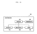
- FIG. 10 is a block diagram illustrating the configuration of a reception device according to a preferred embodiment of the present disclosure.
- a reception device 1000 may include a reception unit 1010 , a demodulation unit 1020 , a decoder 1030 , a control unit 1040 , and a transmission unit 1050 .
- the reception device may include at least one of a Base Station (BS) (or evolved Node B (eNB) or E-UTRAN Node B), a Relay Node (RN), and a terminal (or User Equipment (UE) or Mobile Station (MS) or Subscriber Station (SS)).
- BS Base Station
- eNB evolved Node B
- RN Relay Node
- UE User Equipment
- MS Mobile Station
- SS Subscriber Station
- the transmission device 100 of FIG. 1 and the reception device 1000 may be implemented as one device.
- the reception unit 1010 receives a codeword from the transmission device 100 .
- the codeword may include a control signal and data.
- the received codeword may be generated by puncturing symbol nodes located at even or odd number positions among symbol nodes included in the codeword, classifying the symbol nodes, which need to be additionally punctured, into one or more punctured node groups, and puncturing the symbol nodes which belong to the punctured node groups according to the locations on the codeword where the one or more punctured node groups are arranged.
- the demodulation unit 1020 demodulates the codeword received by the reception unit 1010 .
- the decoder 1030 decodes the codeword demodulated by the demodulation unit 1020 .
- the decoder 1030 may decode the codeword using doping symbols included in the codeword.
- the doping symbol may be used as information that helps an iterative decoder to operate.
- the iterative decoder may be an iterative decoder of an IRPA code.
- the control unit 1040 executes a command and performs an operation related to the reception device 1000 .
- the control unit 1040 may control input/output and data reception/processing between components of the reception device 1000 .
- the control unit 1040 may execute the command related to information received from the input device.
- the control unit 1040 executes a program code together with the operating system of the reception device 1000 , and generates and uses data.
- the control unit 1040 may control the operations of the reception unit 1010 , the demodulation unit 1020 , the decoder 1030 , and the transmission unit 1050 .
- the control unit 1040 may perform the functions of the demodulation unit 1020 and the decoder 1030 .
- the operating system is generally known, the detailed description thereof will be omitted.
- the operating system may be Window series OS, UNIX, Linux, Palm OS, DOS, Android, or Macintosh.
- the operating system, other computer codes, and data may exist in a storage device of the reception device 1000 that is connected to the control unit 1040 to operate.
- the control unit 1040 may be implemented on a single chip, a plurality of chips, or a plurality of electrical components. For example, various architectures including a dedicated or embedded processor, a single purpose processor, a controller, an ASIC, or the like may be used for the control unit 1040 .
- the control unit 1040 may recognize a user action, and may control the reception device 1000 on the basis of the recognized user action.
- the user action may include selection of a physical button of the reception device, execution of a predetermined gesture or selection of a soft button on a touch screen display, execution of a predetermined gesture that is recognized from an image captured by an image capturing device, and execution of predetermined vocalization that is recognized through voice recognition.
- the gesture may include a touch gesture and a spatial gesture.
- the transmission unit 1050 transmits data to another reception device.
- the data may include at least one of a control signal, data, and information related to measurement report.
- the information related to the measurement report may include information on the result of measurement of the channel state.
- the data may be encoded to the codeword to be transmitted.
- FIG. 11 is a block diagram illustrating the configuration of a decoder according to a preferred embodiment of the present disclosure.
- a decoder 1030 may include an inner decoder 1110 , a deinterleaver 1120 , a binary decoder 1130 , and an interleaver 1140 .
- the inner decoder 1110 may perform decoding using a reception channel LLR value that is calculated by the demodulation unit 1020 using a BCJR algorithm using forward/backward recursion and a probability value of the codeword that is output from the interleaver 1140 .
- the inner decoder 1110 may use message values of the (j ⁇ 1)-th and (j+1)-th symbol nodes when decoding the i-th symbol node. That is, the symbol node included in the codeword may be decoded using the message values of symbol nodes in front and in the rear of the symbol node.
- non-punctured nodes are arranged in front and in the rear of the punctured nodes during decoding, and the corresponding nodes receive messages of high reliability from both sides thereof during the decoding.
- the deinterleaver 1120 deinterleaves the codeword decoded by the inner decoder 1110 .
- the binary decoder 1130 decodes the codeword that is deinterleaved by the deinterleaver 1120 and generates data.
- the binary decoder 1130 outputs the codeword to the interleaver 1140 .
- the interleaver 1140 interleaves the codeword that is output from the binary decoder 1130 , and outputs the interleaved codeword to the inner decoder 1110 .
- the interleaver 1140 may be the same as the interleaver 220 located inside the encoder 110 . Accordingly, the decoder 1030 according to the present disclosure generates data by iteratively decoding the codeword through the inner decoder 1110 , the deinterleaver 1120 , the binary decoder 1130 , and the interleaver 1140 .
- FIG. 12 is a flowchart illustrating performing processes of a method for generating a codeword according to a preferred embodiment of the present disclosure.
- the binary encoder 210 encodes data to a codeword (S 100 ).
- the binary encoder 210 may encode the data using a binary code.
- the binary encoder 210 may receive the data from the control unit 140 in the unit of a bit, and may generate the codeword through repetition of all bits as many as a predetermined number of times. Here, the number of repetitions for each bit may not be uniform.
- the codeword that is output from the binary encoder 210 may be a binary data stream.
- the binary code may be an IR code.
- the interleaver 220 interleaves the codeword that is encoded by the binary encoder 210 (S 110 ).
- the interleaver 220 may rearrange binary data streams output from the binary encoder 210 , and may tie up a predetermined number of binary data streams into a group. Further, the interleaver 220 may output bit strings that are tied up into a group to the inner encoder 230 .
- the inner encoder 230 inserts doping symbols into the codeword that is interleaved by the interleaver 220 (S 120 ).
- the inner encoder 230 punctures the codeword into which the doping symbols are inserted (S 130 ).
- the modulation unit 120 modulates the punctured codeword (S 140 ).
- the transmission unit 130 transmits the codeword that is modulated by the modulation unit 120 (S 150 ).
- FIG. 13 is a flowchart illustrating performing processes of a method for generating a codeword according to a preferred embodiment of the present disclosure.
- the inner encoder 110 calculates the number of punctured symbol nodes from the codeword (S 200 ).
- the codeword may be a codeword that is output by the binary encoder 210 or the interleaver 220 .
- the inner encoder 110 confirms whether the target code rate is smaller than 2/3 (S 210 ).
- the inner encoder 230 performs basic puncturing (S 220 ).
- the inner encoder 230 punctures symbol nodes located at even or odd number positions among symbol nodes included in the codeword.
- the symbol nodes to be punctured among the symbol nodes located at even or odd number positions may be determined on the basis of the locations of the doping symbols included in the codeword.
- the inner encoder 230 calculates the number of symbol nodes which need to be additionally punctured on the basis of the calculated number of the symbol nodes to be punctured (S 230 ).
- the inner encoder 230 determines the size of the punctured node group (S 240 ).
- the inner encoder 230 may determine the size of the punctured node group on the basis of the number of symbol nodes which need to be punctured, and may classify the symbol nodes, which need to be additionally punctured, into one or more punctured node groups according to the determined size.
- the inner encoder 230 may determine the size of the punctured node group on the basis of at least one of the size and the number of symbol bands of the codeword.
- the symbol band means a set of a predetermined number of consecutive code symbols including one doping symbol.
- the inner encoder 230 may classify the symbol nodes into one or more punctured node groups on the basis of at least one of the size and the number of symbol bands of the codeword and the size of the punctured node group determined according to a predetermined value.
- the sizes of at least two punctured node groups among the one or more punctured node groups may be equal to each other.
- the inner encoder 230 determines the locations on the codeword where the one or more classified punctured node groups are to be arranged (S 250 ).
- each of the one or more punctured node groups may be arranged in the center of the symbol band of the codeword.
- a plurality of punctured node groups may be arranged on at least one of the symbol bands of the codeword.
- the number of punctured node groups arranged on the symbol band may be determined on the basis of at least one of the doping symbol and the target code rate of the codeword, and the number of punctured node groups arranged on at least one of the symbol bands of the codeword may be different from the number of punctured node groups arranged on another symbol band.
- the inner encoder 230 punctures the symbol nodes included in the codeword that belong to the punctured node groups according to the determined locations (S 260 ).
- the inner encoder 110 punctures the symbol nodes included in the codeword so that the punctured nodes are uniformly arranged on the codeword (S 270 ).
- the target code rate may be a code rate of the codeword that is output to the modulation unit 120 .
- operation S 130 of FIG. 12 may include operations S 200 to S 260 .
- FIG. 14 is a flowchart illustrating performing processes of a method for generating a codeword according to another preferred embodiment of the present disclosure.
- Operation S 300 may include operations S 200 to S 260 of FIG. 13 .
- the inner encoder 230 calculates the number of punctured nodes to be unpunctured in the codeword punctured at the first target code rate (S 310 ).
- the first target code rate and the second target code rate may be different from each other, and the second target code rate may be higher than the first target code rate.
- the inner encoder 230 unpunctures the punctured nodes in the codeword according to the calculated number of punctured nodes (S 320 ).
- the punctured nodes that belong to the punctured node group may be first unpunctured.
- operation S 130 of FIG. 12 may include operations S 300 to S 320 of FIG. 13 .
- FIG. 15 is a flowchart illustrating performing processes of a method for decoding a codeword according to a preferred embodiment of the present disclosure.
- the reception unit 1010 receives the codeword from the transmission device 100 (S 400 ).
- the codeword may include a control signal and data.
- the received codeword may be generated by puncturing symbol nodes located at even or odd number positions among symbol nodes included in the codeword, classifying the symbol nodes, which need to be additionally punctured, into one or more punctured node groups, and puncturing the symbol nodes which belong to the punctured node groups according to the locations on the codeword where the one or more punctured node groups are arranged.
- the demodulation unit 1020 demodulates the codeword received by the reception unit 1010 (S 410 ).
- the decoder 1030 decodes the codeword demodulated by the demodulation unit 1020 (S 420 ).
- the decoder 1030 may decode the codeword using doping symbols included in the codeword.
- the doping symbol may be used as information that helps an iterative decoder to operate.
- the iterative decoder may be an iterative decoder of an IRPA code.
- FIG. 16 is a graph illustrating the performance of a method for generating a codeword.
- a graph 1600 shows the performance of a puncturing pattern in which the codeword is encoded at a code rate of 2/3 in an Additive White Gaussian Noise (AWGN) channel in the case where information bits are 960, the modulation order is 16, and a doping period is 30.
- AWGN Additive White Gaussian Noise
- a curve 1610 indicates the performance of a puncturing pattern that is designed by a method (conventional method) for designing a puncturing pattern using the concept of a k-Step Recoverable node that is applied to the puncturing of an LDPC code
- a curve 1620 indicates the performance of a puncturing pattern that is designed so that the size of the punctured node group becomes 13 using a method for generating a codeword according to the present disclosure as illustrated in FIG. 8 .
- a curve 1630 indicates the performance of a puncturing pattern that is designed so that the size of the punctured node group becomes 25 using a method for generating a codeword according to the present disclosure as illustrated in FIG. 8
- a curve 1640 indicates the performance for the original codeword.
- the method 1620 according to the present disclosure has improved the performance by about 0.1 dB at the Frame Error Rate (FER) of 10 ⁇ -2 in comparison to the conventional method 1610 .
- the method 1630 according to the present disclosure has improved the performance by about 0.2 dB at the Frame Error Rate (FER) of 10 ⁇ -2 in comparison to the conventional method 1610 .
- FIG. 17 is another graph illustrating the performance of a method for generating a codeword.
- a graph 1700 shows the performance of a puncturing pattern in which the codeword is encoded at a code rate of 5/6 in an Additive White Gaussian Noise (AWGN) channel in the case where information bits are 960, the modulation order is 16, and a doping period is 30.
- AWGN Additive White Gaussian Noise
- a curve 1710 indicates the performance of a puncturing pattern that is designed by a method (conventional method) for designing a puncturing pattern using the concept of a k-Step Recoverable node that is applied to the puncturing of an LDPC code
- a curve 1720 indicates the performance of a puncturing pattern that is designed so that the size of the punctured node group becomes 13 using a method for generating a codeword according to the present disclosure as illustrated in FIG. 8 .
- a curve 1730 indicates the performance of a puncturing pattern that is designed so that the size of the punctured node group becomes 25 using a method for generating a codeword according to the present disclosure as illustrated in FIG. 8 .
- the method 1730 according to the present disclosure has improved the performance by about 0.5 dB at the Frame Error Rate (FER) of 10 ⁇ -2 in comparison to the method 1720 according to the present disclosure.
- FER Frame Error Rate
Landscapes
- Engineering & Computer Science (AREA)
- Signal Processing (AREA)
- Multimedia (AREA)
- Computer Networks & Wireless Communication (AREA)
- Computer Security & Cryptography (AREA)
- Databases & Information Systems (AREA)
- Probability & Statistics with Applications (AREA)
- Theoretical Computer Science (AREA)
- Physics & Mathematics (AREA)
- Health & Medical Sciences (AREA)
- General Health & Medical Sciences (AREA)
- Social Psychology (AREA)
- Error Detection And Correction (AREA)
Abstract
Description
i=sD+j [Mathematical Expression 1]
j=2k,k=0,1, . . . ,D/2−1 if s≤N D−1 and k=0, . . . ,└N D/2┘−1 if s=N D (Basic puncturing condition)
sD+η≤i≤sD+η+2(N p−1),s∈T p
sD+η≤i≤sD+η+2(N p′−1),s∈T p′ (Additional puncturing condition 1)
N p ′=N p+1 [Mathematical Expression 3]
sD+η≤i≤sD+η+2(τ−1) (Additional puncturing condition 2)
sD+η 1 ≤i≤sD+η 1+2(τ−1) (Additional puncturing condition 3)
sD+η k ≤i≤sD+η k+2(τ−1) (Additional puncturing condition 4)
νs =└s·
Claims (20)
Applications Claiming Priority (4)
| Application Number | Priority Date | Filing Date | Title |
|---|---|---|---|
| KR10-2014-0046245 | 2014-04-17 | ||
| KR1020140046245A KR102191303B1 (en) | 2014-04-17 | 2014-04-17 | a method amd an apparatus for generating a codeword and a method and an apparatus of recovering a codeword |
| KR10-2014-0046252 | 2014-04-17 | ||
| PCT/KR2015/003843 WO2015160205A1 (en) | 2014-04-17 | 2015-04-16 | Method and apparatus for generating codeword, and method and apparatus for recovering codeword |
Publications (2)
| Publication Number | Publication Date |
|---|---|
| US20170188367A1 US20170188367A1 (en) | 2017-06-29 |
| US10070441B2 true US10070441B2 (en) | 2018-09-04 |
Family
ID=54428524
Family Applications (1)
| Application Number | Title | Priority Date | Filing Date |
|---|---|---|---|
| US15/304,844 Active 2035-06-28 US10070441B2 (en) | 2014-04-17 | 2015-04-16 | Method and apparatus for generating codeword, and method and apparatus for recovering codeword |
Country Status (4)
| Country | Link |
|---|---|
| US (1) | US10070441B2 (en) |
| EP (1) | EP3133785B1 (en) |
| KR (1) | KR102191303B1 (en) |
| CN (1) | CN106233683B (en) |
Cited By (1)
| Publication number | Priority date | Publication date | Assignee | Title |
|---|---|---|---|---|
| US11146355B2 (en) * | 2017-05-02 | 2021-10-12 | Samsung Electronics Co., Ltd. | Method and apparatus for channel encoding/decoding in communication or broadcast system |
Families Citing this family (2)
| Publication number | Priority date | Publication date | Assignee | Title |
|---|---|---|---|---|
| CN108391096B (en) * | 2018-04-15 | 2019-01-08 | 郑锋 | Indoor liveness real-time measurement system |
| IL277711B (en) * | 2020-09-30 | 2022-01-01 | Elbit Systems C4I & Cyber Ltd | Transmission device and method for transmitting punctured data messages having common input bits and reception device and method for reassembling an encoded data message based on punctured data messages |
Citations (16)
| Publication number | Priority date | Publication date | Assignee | Title |
|---|---|---|---|---|
| US20020114401A1 (en) | 2001-02-16 | 2002-08-22 | Samsung Electronics Co., Ltd. | Apparatus and method for generating and decoding codes in a communication system |
| US20040133841A1 (en) * | 2000-06-02 | 2004-07-08 | Stein Lundby | Method and apparatus for puncturing code symbols in a communications system |
| US20070288834A1 (en) | 2006-05-26 | 2007-12-13 | Crozier Stewart N | Puncture-Constrained Interleaving For Concatenated Codes |
| US20080072124A1 (en) * | 2006-09-05 | 2008-03-20 | Mediatek Inc. | Apparatus and method for detecting puncture position in a symbol stream encoded by punctured convolutional coding scheme |
| US7409001B2 (en) * | 2004-08-12 | 2008-08-05 | Nokia Corporation | Method and apparatus using coordinate interleaving to increase diversity in a MIMO system |
| KR20080104684A (en) | 2007-05-29 | 2008-12-03 | 연세대학교 산학협력단 | Method for puncturing of block type low density parity check code |
| US20090259913A1 (en) | 2008-03-03 | 2009-10-15 | Samsung Electronics Co., Ltd. | Method for encoding control information in a wireless communication system using low density parity check code, and method and apparatus for transmitting and receiving the control information |
| US7657822B2 (en) * | 2002-05-31 | 2010-02-02 | Broadcom Corporation | True bit level decoding of TTCM (turbo trellis code modulation) of variable rates and signal constellations |
| US8031793B2 (en) * | 2005-01-19 | 2011-10-04 | Dumitru Mihai Ionescu | Apparatus using concatenations of signal-space codes for jointly encoding across multiple transmit antennas, and employing coordinate interleaving |
| US20120096336A1 (en) * | 2009-03-03 | 2012-04-19 | Osamu Nakamura | Transmission Apparatus Reception Apparatus and Communication System |
| KR20120056443A (en) | 2010-11-25 | 2012-06-04 | 주식회사 케이티 | Method and Apparatus for Real-time Joint Source-Channel Coding |
| US20120166917A1 (en) | 2006-01-06 | 2012-06-28 | Qualcomm Incorporated | System and method for providing h-arq rate compatible codes for high throughput applications |
| US20120216099A1 (en) | 2011-02-22 | 2012-08-23 | Postech Academy-Industry Foundation | Method and apparatus for transmitting signaling information in digital broadcasting system |
| KR101267756B1 (en) | 2012-03-06 | 2013-05-24 | 단국대학교 산학협력단 | Method for encoding and decoding rate-compatible irregular repeat multiple-state accumulate codes and apparatuses using the same |
| US20140079150A1 (en) * | 2012-09-14 | 2014-03-20 | Cambridge Silicon Radio Limited | Data encoding methods and apparatus |
| KR20140036346A (en) | 2008-03-03 | 2014-03-25 | 삼성전자주식회사 | Method and apparatus for transmitting and receiving control information in a communication system |
Family Cites Families (3)
| Publication number | Priority date | Publication date | Assignee | Title |
|---|---|---|---|---|
| JP2007312156A (en) * | 2006-05-19 | 2007-11-29 | Kddi Corp | Error correction code data retransmission control method, radio apparatus, and program |
| KR101695824B1 (en) * | 2009-01-23 | 2017-01-13 | 엘지전자 주식회사 | Apparatus For Transmitting And Receiving A Signal And Method Of Tranmsitting And Receiving A Signal |
| KR102127021B1 (en) * | 2012-05-11 | 2020-06-26 | 블랙베리 리미티드 | Method and system for uplink harq and csi multiplexing for carrier aggregation |
-
2014
- 2014-04-17 KR KR1020140046245A patent/KR102191303B1/en active Active
-
2015
- 2015-04-16 EP EP15779293.8A patent/EP3133785B1/en active Active
- 2015-04-16 US US15/304,844 patent/US10070441B2/en active Active
- 2015-04-16 CN CN201580020315.5A patent/CN106233683B/en active Active
Patent Citations (17)
| Publication number | Priority date | Publication date | Assignee | Title |
|---|---|---|---|---|
| US20040133841A1 (en) * | 2000-06-02 | 2004-07-08 | Stein Lundby | Method and apparatus for puncturing code symbols in a communications system |
| JP3636709B2 (en) | 2001-02-16 | 2005-04-06 | サムスン エレクトロニクス カンパニー リミテッド | Code generation and decoding apparatus and method in communication system |
| US20020114401A1 (en) | 2001-02-16 | 2002-08-22 | Samsung Electronics Co., Ltd. | Apparatus and method for generating and decoding codes in a communication system |
| US7657822B2 (en) * | 2002-05-31 | 2010-02-02 | Broadcom Corporation | True bit level decoding of TTCM (turbo trellis code modulation) of variable rates and signal constellations |
| US7409001B2 (en) * | 2004-08-12 | 2008-08-05 | Nokia Corporation | Method and apparatus using coordinate interleaving to increase diversity in a MIMO system |
| US8031793B2 (en) * | 2005-01-19 | 2011-10-04 | Dumitru Mihai Ionescu | Apparatus using concatenations of signal-space codes for jointly encoding across multiple transmit antennas, and employing coordinate interleaving |
| US20120166917A1 (en) | 2006-01-06 | 2012-06-28 | Qualcomm Incorporated | System and method for providing h-arq rate compatible codes for high throughput applications |
| US20070288834A1 (en) | 2006-05-26 | 2007-12-13 | Crozier Stewart N | Puncture-Constrained Interleaving For Concatenated Codes |
| US20080072124A1 (en) * | 2006-09-05 | 2008-03-20 | Mediatek Inc. | Apparatus and method for detecting puncture position in a symbol stream encoded by punctured convolutional coding scheme |
| KR20080104684A (en) | 2007-05-29 | 2008-12-03 | 연세대학교 산학협력단 | Method for puncturing of block type low density parity check code |
| US20090259913A1 (en) | 2008-03-03 | 2009-10-15 | Samsung Electronics Co., Ltd. | Method for encoding control information in a wireless communication system using low density parity check code, and method and apparatus for transmitting and receiving the control information |
| KR20140036346A (en) | 2008-03-03 | 2014-03-25 | 삼성전자주식회사 | Method and apparatus for transmitting and receiving control information in a communication system |
| US20120096336A1 (en) * | 2009-03-03 | 2012-04-19 | Osamu Nakamura | Transmission Apparatus Reception Apparatus and Communication System |
| KR20120056443A (en) | 2010-11-25 | 2012-06-04 | 주식회사 케이티 | Method and Apparatus for Real-time Joint Source-Channel Coding |
| US20120216099A1 (en) | 2011-02-22 | 2012-08-23 | Postech Academy-Industry Foundation | Method and apparatus for transmitting signaling information in digital broadcasting system |
| KR101267756B1 (en) | 2012-03-06 | 2013-05-24 | 단국대학교 산학협력단 | Method for encoding and decoding rate-compatible irregular repeat multiple-state accumulate codes and apparatuses using the same |
| US20140079150A1 (en) * | 2012-09-14 | 2014-03-20 | Cambridge Silicon Radio Limited | Data encoding methods and apparatus |
Non-Patent Citations (8)
| Title |
|---|
| Albert Guillen, et al., "Capacity Approaching Codes for Non-Coherent Orthogonal Modulation", IEEE Transactions on Wireless Communications, vol. 6, No. 11, Nov. 2007, 10 pages. |
| Brink, Stephan Ten, "Code Doping for Triggering Iterative Decoding Convergence," Proceedings of the 2001 IEEE International Symposium on Information Theory, ISIT2001, Washington, DC, Jun. 24-29, 2001, 1 page. |
| Communication from a foreign patent office in a foreign counterpart application, European Patent Office, "Supplementary European Search Report," Application No. EP 15 77 9293.8, dated Jan. 4, 2018, 11 pages. |
| Ghosh, Arindam, et al., "Throughput and Energy Efficiency of a Cooperative Hybrid ARQ Protocol for Underwater Acoustic Sensor Networks," Sensors 2013, vol. 13, No. 11, Nov. 8, 2013, ISSN 1424-8220, doi:10.3390/s131115385, 24 pages. |
| International Search Report dated Jul. 23, 2015 in connection with International Patent Application No. PCT/KR2015/003843, 7 pages. |
| Jeongseok Ha, et al., Puncturing for Finite Length Low-Density Parity-Check Codes, ISIT 2004, IEEE, Chicago, Illinois, Jun. 27-Jul. 2, 2004, 1 page. |
| Wikipedia, "Puncturing," https://en.wikipedia.org/w/index.php?title=Puncturing&oldid=602381624, Apr. 2, 2014, 1 page. |
| Written Opinion of the International Searching Authority dated Jul. 23, 2015 in connection with International Patent Application No. PCT/KR2015/003843, 8 pages. |
Cited By (2)
| Publication number | Priority date | Publication date | Assignee | Title |
|---|---|---|---|---|
| US11146355B2 (en) * | 2017-05-02 | 2021-10-12 | Samsung Electronics Co., Ltd. | Method and apparatus for channel encoding/decoding in communication or broadcast system |
| US11569936B2 (en) * | 2017-05-02 | 2023-01-31 | Samsung Electronics Co., Ltd. | Method and apparatus for channel encoding/decoding in communication or broadcast system |
Also Published As
| Publication number | Publication date |
|---|---|
| KR20150120235A (en) | 2015-10-27 |
| US20170188367A1 (en) | 2017-06-29 |
| EP3133785A1 (en) | 2017-02-22 |
| CN106233683A (en) | 2016-12-14 |
| EP3133785B1 (en) | 2022-02-23 |
| CN106233683B (en) | 2020-03-03 |
| EP3133785A4 (en) | 2018-01-24 |
| KR102191303B1 (en) | 2020-12-15 |
Similar Documents
| Publication | Publication Date | Title |
|---|---|---|
| EP3512137B1 (en) | Pbch transmitting method and transmitting device, and pbch receiving method and receiving device | |
| US20240031058A1 (en) | Encoding and modulation method, demodulation and decoding method, and apparatus | |
| CN105306165B (en) | Data sending method and device | |
| EP2181505B1 (en) | Multi-layer cyclic redundancy check code in wireless communication system | |
| CN110249539B (en) | Polar code interleaving and bit selection | |
| US11258535B2 (en) | Method and apparatus for transmitting information | |
| US20170359150A1 (en) | Data checking method and device | |
| US11139836B2 (en) | Information transmission method and transmission device, and information reception method and reception device | |
| US10887050B2 (en) | Downlink signal reception method and user equipment, and downlink signal transmission method and base station | |
| US11223370B2 (en) | Method and apparatus for transmitting information | |
| CN114124292A (en) | Retransmission method and device | |
| US10070441B2 (en) | Method and apparatus for generating codeword, and method and apparatus for recovering codeword | |
| CN113328828B (en) | Information processing method, terminal, chip and storage medium | |
| US10581464B2 (en) | Encoder device, decoder device, and methods thereof | |
| CN117918053A (en) | Method and apparatus for wireless communication retransmission using check blocks generated according to a sub-block interleaver | |
| WO2017101023A1 (en) | Communication method, network device, and user equipment | |
| US20260067028A1 (en) | Method, communication device, processing device, and storage medium for transmitting information block, and method, communication device, processing device, and storage medium for receiving information block | |
| WO2024192763A1 (en) | Methods, systems, and apparatus for non-sequential decoding of polar codes | |
| US20260081722A1 (en) | Methods, systems, and apparatus for rateless polar coding and low-complexity decoding | |
| EP4648316A1 (en) | Method, communication device, processing device, and storage medium for performing encoding, and method and communication device for performing decoding | |
| EP4708740A1 (en) | Method, communication device, processing device, and storage medium for transmitting information block, and method, communication device, processing device, and storage medium for receiving information block | |
| JP2013118715A (en) | Transmitter, receiver, communication system, and communication method |
Legal Events
| Date | Code | Title | Description |
|---|---|---|---|
| AS | Assignment |
Owner name: SAMSUNG ELECTRONICS CO., LTD, KOREA, REPUBLIC OF Free format text: ASSIGNMENT OF ASSIGNORS INTEREST;ASSIGNORS:PARK, WOOMYOUNG;KIM, SANGMIN;LIM, CHIWOO;SIGNING DATES FROM 20160802 TO 20161004;REEL/FRAME:040035/0659 |
|
| FEPP | Fee payment procedure |
Free format text: PETITION RELATED TO MAINTENANCE FEES GRANTED (ORIGINAL EVENT CODE: PTGR); ENTITY STATUS OF PATENT OWNER: LARGE ENTITY |
|
| STCF | Information on status: patent grant |
Free format text: PATENTED CASE |
|
| MAFP | Maintenance fee payment |
Free format text: PAYMENT OF MAINTENANCE FEE, 4TH YEAR, LARGE ENTITY (ORIGINAL EVENT CODE: M1551); ENTITY STATUS OF PATENT OWNER: LARGE ENTITY Year of fee payment: 4 |
|
| MAFP | Maintenance fee payment |
Free format text: PAYMENT OF MAINTENANCE FEE, 8TH YEAR, LARGE ENTITY (ORIGINAL EVENT CODE: M1552); ENTITY STATUS OF PATENT OWNER: LARGE ENTITY Year of fee payment: 8 |