JP3636709B2 - Code generation and decoding apparatus and method in communication system - Google Patents
Code generation and decoding apparatus and method in communication system Download PDFInfo
- Publication number
- JP3636709B2 JP3636709B2 JP2002566845A JP2002566845A JP3636709B2 JP 3636709 B2 JP3636709 B2 JP 3636709B2 JP 2002566845 A JP2002566845 A JP 2002566845A JP 2002566845 A JP2002566845 A JP 2002566845A JP 3636709 B2 JP3636709 B2 JP 3636709B2
- Authority
- JP
- Japan
- Prior art keywords
- symbol
- symbols
- sequence
- symbol sequence
- code
- Prior art date
- Legal status (The legal status is an assumption and is not a legal conclusion. Google has not performed a legal analysis and makes no representation as to the accuracy of the status listed.)
- Expired - Lifetime
Links
Images


Classifications
-
- H—ELECTRICITY
- H03—ELECTRONIC CIRCUITRY
- H03M—CODING; DECODING; CODE CONVERSION IN GENERAL
- H03M13/00—Coding, decoding or code conversion, for error detection or error correction; Coding theory basic assumptions; Coding bounds; Error probability evaluation methods; Channel models; Simulation or testing of codes
- H03M13/27—Coding, decoding or code conversion, for error detection or error correction; Coding theory basic assumptions; Coding bounds; Error probability evaluation methods; Channel models; Simulation or testing of codes using interleaving techniques
- H03M13/2771—Internal interleaver for turbo codes
-
- H—ELECTRICITY
- H03—ELECTRONIC CIRCUITRY
- H03M—CODING; DECODING; CODE CONVERSION IN GENERAL
- H03M13/00—Coding, decoding or code conversion, for error detection or error correction; Coding theory basic assumptions; Coding bounds; Error probability evaluation methods; Channel models; Simulation or testing of codes
- H03M13/29—Coding, decoding or code conversion, for error detection or error correction; Coding theory basic assumptions; Coding bounds; Error probability evaluation methods; Channel models; Simulation or testing of codes combining two or more codes or code structures, e.g. product codes, generalised product codes, concatenated codes, inner and outer codes
- H03M13/2957—Turbo codes and decoding
-
- H—ELECTRICITY
- H03—ELECTRONIC CIRCUITRY
- H03M—CODING; DECODING; CODE CONVERSION IN GENERAL
- H03M13/00—Coding, decoding or code conversion, for error detection or error correction; Coding theory basic assumptions; Coding bounds; Error probability evaluation methods; Channel models; Simulation or testing of codes
- H03M13/63—Joint error correction and other techniques
- H03M13/6306—Error control coding in combination with Automatic Repeat reQuest [ARQ] and diversity transmission, e.g. coding schemes for the multiple transmission of the same information or the transmission of incremental redundancy
-
- H—ELECTRICITY
- H03—ELECTRONIC CIRCUITRY
- H03M—CODING; DECODING; CODE CONVERSION IN GENERAL
- H03M13/00—Coding, decoding or code conversion, for error detection or error correction; Coding theory basic assumptions; Coding bounds; Error probability evaluation methods; Channel models; Simulation or testing of codes
- H03M13/63—Joint error correction and other techniques
- H03M13/635—Error control coding in combination with rate matching
- H03M13/6362—Error control coding in combination with rate matching by puncturing
- H03M13/6368—Error control coding in combination with rate matching by puncturing using rate compatible puncturing or complementary puncturing
- H03M13/6387—Complementary punctured convolutional [CPC] codes
Description
【0001】
【発明の属する技術分野】
本発明は、データ通信システムにおける符号生成装置に関し、特に、再伝送方式(Automatic Repeat request: 以下、ARQと称する)を使用するパケット通信システムまたはARQ方式を使用する一般的な通信システムにおいてターボ符号の特性を考慮した補完ターボ符号(complementary turbo codes)生成装置及び方法に関する。
【0002】
一般的に、ハイブリッドARQ(Hybrid ARQ: 以下、HARQと称する)方式を使用するシステムは、伝送効率(throughput)の向上のために軟性結合(Soft combining)を使用し、前記軟性結合は、パケットダイバーシティ結合(packet diversity combining)とパケット符号結合(packet code combining)に分けられる。前記2つの結合方式を軟性パケット結合(Soft Packet Combining)と称する。前記パケットダイバーシティ結合方式は、前記パケット符号結合に比べて、性能面で次善の方式であるが、具現の便宜性のため、性能上の大きな損失が無い場合はよく使用される。
【0003】
前記パケット符号結合方式は、パケット伝送システムにおいて伝送効率(Throughput)を増加させるために使用される。前記パケット符号結合方式は、伝送されるそれぞれのパケットに対して符号率Rを有する多様な符号を伝送する。復号の結果、前記受信されたパケットからエラーが検出される場合、受信器は、前記エラーが検出されたパケットを捨てるより貯蔵した後、前記貯蔵されたパケットを送信器によって再伝送されるパケットと軟性結合(Soft Combining)する。ここで、前記再伝送されるパケットは、異なる符号が使用されることができる。つまり、前記パケット符号結合方式は、符号率Rを有するN個のパケットを受信する場合、前記パケットを使用して前記符号率を実効符号率(effective code rate)R/Nに転換した後に復号することによって符号化利得(coding gain)を得ることができる。
【0004】
反面、前記パケットダイバーシティ結合は、伝送されるそれぞれのパケットに対して符号率Rを有する同一の符号を伝送し、復号の結果、前記受信されたパケットからエラーが検出される場合、前記受信器は、前記エラーが検出されたパケットを捨てるより貯蔵した後、前記貯蔵されたパケット前記送信器から再伝送されるパケットと軟性結合する。全てのケースにおいて、前記再伝送されるパケットは、同一の符号が使用される。従って、前記パケットダイバーシティ結合は、ランダムチャネルにおいて一種のシンボルエネルギー平均過程(Symbol Energy Averaging process)としてみなされることができ、受信されたシンボルの軟性出力(soft output)を平均することによって得られる雑音電力減少効果、及びフェーディングチャネル(fading channel)において複数のシンボルを伝送することによってダイバーシティチャネルで提供されるダイバーシティ利得(diversity gain)のみを使用する。それに反して、前記パケット符号結合は、前記ダイバーシティ利得の以外にコード構造による追加的な符号化利得を有する。
【0005】
以下、前記ターボ符号を生成するターボ符号器を説明する。例えば、符号率が1/5であるターボ符号器は、入力される情報シンボルを符号化することによって、情報シンボルX、第1パリティシンボY0、Y0'、及び第2パリティシンボルY1、Y1'を発生する。前記ターボ符号器は、2つの構成符号器(component encoder)及び1つのインターリーバ(interleaver)から構成される。第1構成符号器は、前記入力される情報シンボルを符号化して前記第1パリティシンボY0、Y0'を発生し、第2構成符号器は、前記インターリーバを通してインターリーブされた情報シンボルを符号化して第2パリティシンボルY1、Y1'を発生する。詳細に、前記Y0は、第1構成符号器から発生される1番目のパリティシンボルの列であり、前記Y0'は、前記第1構成符号器から発生される2番目のパリティシンボルの列である。
【0006】
現在まで、大部分のパケット通信システムは、具現の容易さのため、パケットダイバーシティ結合を使用した。特に、同期方式のIS−2000システム及び非同期方式のUMTSシステムは、前述した理由によって前記パケットダイバーシティ結合方式を使用している。しかしながら、既存の大部分のパケット通信システムはコンボルーション符号(convolutional code)を使用し、低い符号率Rを有するコンボルーション符号を使用する場合は、前記パケットダイバーシティ結合を使用するとしても、大きな利得を提供することができない。つまり、R=1/3の従来の符号を使用するシステムがARQ方式を支援する場合、前記パケットダイバーシティ結合方式と前記パケット符号結合方式との性能差があまり大きくないので、前記システムは、前記パケットダイバーシティ結合を使用した。しかしながら、エラー訂正符号(Forward Error Correction Codes : FEC)としてターボ符号を使用する場合は、既存とは異なる方式が要求される。これは、前記ターボ符号が反復復号(iterative decoding)によってその性能がシャノンチャンネルキャパシティリミット(Shannon Channel Capacity Limit)に近接するように設計され、既存のコンボルーション符号とは異なって前記符号率による性能差が明確に存在するためである。従って、システムの性能を向上させるためには、パケット通信システムにおいてターボ符号を使用する前記パケット符号結合方式を使用することは望ましい。
【0007】
【発明が解決しようとする課題】
従って、本発明の目的は、通信システムにおいてターボ符号の特性を考慮した補完ターボ符号の生成及び復号装置及び方法を提供することにある。
本発明の他の目的は、通信システムにおいて、準補完ターボ符号(Quasi Complementary Turbo Codes: 以下、QCTCと称する)を生成するための装置及び方法を提供することにある。
本発明のまた他の目的は、通信システムにおいて準補完ターボ符号を復号するための装置及び方法を提供することにある。
【0008】
【課題を解決するための手段】
前述した目的を達成するために、本発明は、通信システムにおいて準補完ターボ符号を発生する装置を提供する。前記装置は、ターボ符号器、所定の規則によって前記ターボ符号器から出力されるシンボルをインターリーブするインターリーバ、及び前記インターリーバからの前記インターリーブされたシンボルを穿孔及び反復することによって前記準補完ターボ符号を発生する符号生成器から構成される。
【0009】
本発明は、通信システムにおいて準補完ターボ符号を復号する装置を提供する。前記装置は、送信器から伝送された準補完ターボ符号のサブ符号の逆穿孔(depuncturing)を通して伝送される伝送率によって符号シンボルを発生し、前記サブ符号を軟性結合(soft combining)する符号復号器、前記符号復号器から出力されたシンボルをデインターリービングするデインターリーバ、及び前記デインターリーバの出力を復号化するターボ復号器と、から構成される。
【0010】
【発明の実施の形態】
以下、本発明に従う好適な実施形態について添付図を参照しつつ詳細に説明する。下記の説明において、本発明の要旨のみを明確にする目的で、関連した公知機能または構成に関する具体的な説明は省略する。
本発明は、準補完ターボ符号(QCTC)を使用してチャネルインターリービングを支援するシステム、または、多様な符号率を有するQCTCを要求するシステムにおいて、符号長の変化に関係なく準補完ターボ符号を使用する方式を提供する。前記QCTCは、ターボ符号を使用して生成される補完符号(Complementary Codes)と定義されている。前記QCTCは、準(quasi)という用語を使用することから分かるように、サブ符号が反復されるシンボルを含み、それぞれのサブ符号は異なる特性(例えば、エラー訂正能力など)を有するので、完全な補完符号ではない。
【0011】
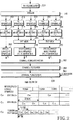
図1は、本発明の実施形態によるQCTC生成装置の構成を示す。図1は、前記QCTC生成装置に使用されるシンボル反復及び穿孔がチャネルインターリービングの後に遂行されることを示す。
図1を参照すると、符号器(encoder)101は、入力されるエンコーダパケット(encoder packet)を符号化シンボルに符号化する。ここで、符号器としては、コンボルーション符号器及びターボ符号器を使用することができる。例えば、前記符号器101の符号率Rが1/5であると仮定する。従って、前記符号器101は、3072ビットの情報ビットを受信し、15360ビットの符号化シンボルを出力する。チャネルインターリーバ(channel interleaver)102は、前記符号器101から出力された前記符号化シンボルを所定の規則によってインターリーブする。ここで、前記インターリーバ102は、前記符号器101がターボ符号器である場合、前記ターボ符号器の性質に基づいて符号語シンボルX、パリティシンボルY0、Y1、Y0'、Y1'を独立的にインターリーブする。QCTC生成器(QCTC generator)(または、QCTC puncturing/repetition block)103は、前記チャネルインターリーバ102から提供された前記インターリーブされたシンボルに対して穿孔(puncturing)及び反復(repetition)を遂行して準補完ターボ符号を生成する。前述したように、前記チャネルインターリーバ102及び前記QCTC生成器103は、QCTC生成過程を遂行する。
【0012】
インターリーブされた符号シンボルの個数が15360であり、与えられたサブ符号の符号率(または、伝送率)が307.2kbpsである場合、前記QCTC生成器103は、前記15360個のインターリーブされた符号シンボル及び反復によって前記インターリーブされた符号シンボルの前半部を選択して、21504個のシンボルを有する1番目のサブ符号を生成する。一方、サブ符号の伝送率が614.4kbpsである場合、前記QCTC生成器103は、前記インターリーブされた符号シンボルの前半部から最初の10752個の符号シンボルを選択して1番目のサブ符号を生成する。さらに、伝送率が1228.8kbpsまたは2457.6kbpsである場合、前記QCTC生成器103は、前記インターリーブされた符号シンボルから最初の5376個の符号シンボルを選択して1番目のサブ符号を生成する。
【0013】
ここで、前記QCTC(または、サブ符号)を生成するために、前記チャネルインターリーバ102は特別に設計されるべきである。これは、前記チャネル符号器101から出力される5個のシンボル、つまり、符号語シンボルX及びパリティシンボルY0、Y1、Y0'、Y1'がチャネルインターリーブされた後、分散されるからである。前記QCTCを生成するための穿孔及び反復ブロックへの入力として前記分散されたシンボルを使用することは容易でなく、さらに、シンボルX、Y0、Y1、Y0'、Y1'がミックスされたシンボルを使用してQCTCの性質を満足するサブ符号を生成することは容易でない。この問題点を解決するために、本発明は、前記サブ符号の符号率に関係なく一定の方式によって前記QCTCを生成する方法を提供する。
【0014】
図2は、本発明の実施形態による準補完ターボ符号を生成するための手順を示す図である。図2を参照すると、符号器(encoder)201は、入力されるエンコーダパケット(encoder packet)をシンボルに符号化する。前記符号器201は、多様な符号率の母符号を使用する。例えば、ここでは、R=1/5のターボ符号を母符号として使用する。前記符号器201は、入力される情報シンボルを符号化することによって、情報シンボルX、第1パリティシンボY0、Y0'、及び第2パリティシンボルY1、Y1'を発生する。前記第1パリティシンボY0、Y0'は、第1構成符号器から出力され、前記第2パリティシンボルY1、Y1'は第2構成符号器から出力される。前記第1及び第2構成符号器(図示せず)は、前記符号器201に含まれる。前記第1及び第2構成符号器から発生される1番目のパリティシンボルY0及びY1は、2番目のパリティシンボルY0'及びY1'より高い伝送優先順位を有する。
【0015】
逆多重化器(demultiplexer)202は、前記チャネル符号器201から出力される5つのシンボル、つまり、符号語シンボルX、パリティシンボルY0、Y1、Y0'、Y1'を5個のグループに逆多重化する。つまり、符号語シンボルX、パリティシンボルルY0、Y1、Y0'、Y1'は、順次、逆多重化された後、それぞれサブブロックインターリーバ(sub-block interleaver)204、214、224、234に提供される。前記サブブロックインターリーバ204、214、224、234は、前記逆多重化器202から出力されるシーケンスをサブブロックインターリービングによってランダムに位置を変更する。下記の条件を満足するように多様なサブブロックインターリービング方式を使用することができる。
(条件1)インターリーブされたシンボルは、インターリービング以前の符号シンボルの穿孔パターンが均等の穿孔距離を有するように部分的に穿孔される。
【0016】
前記条件1を満足する理由は、それぞれの符号語シンボルX、Y0、Y1、Y0'、Y1'から所定の数のシンボルが穿孔される場合、ターボ符号の性能を最適にするためにはサブブロックインターリービング以前の符号語シンボルにおいて穿孔されたシンボル間の距離が均等になるべきであるためである。つまり、ターボ符号に穿孔を使用する場合、均一性(uniformity)が前記ターボ符号の性能を決定する重要な要因になる。本発明によると、前記符号語シンボルX、Y0、Y1、Y0'、Y1'に対して独立的なサブブロックインターリービングを使用する。それぞれのインターリーバの出力において穿孔が均一である場合、符号器の出力において穿孔された符号シンボル間の距離は均一に維持される。従って、インターリーブされた符号シンボルにおける穿孔がチャネル符号器の出力における穿孔分布を均一に維持することができるようにチャネルインターリービング方式が選択されるべきである。
【0017】
前述したチャネルインターリービング方式には、ビット逆順(Bit Reversal Order: BRO)インターリービング及び部分ビット逆順(Partial Bit Reversal Order: PBRO)インターリービングがある。前記BROインターリービングは、符号器に入力される情報語シンボルの個数及び母符号から発生される前記符号語シンボルX、Y0、Y1、Y0'、Y1'においてのシンボルの個数が2の自乗の形態、つまり、2mの形態を有する時のみに使用できる。ここで、mは、サブブロックインターリーバのブロックサイズNを2m×Jにするためのパラメータである。前記PBROインターリービングは、前記BROインターリービングの短所を克服するために、それぞれの符号語シンボルX、Y0、Y1、Y0'、Y1'においてのシンボルの数が2の自乗の形態でない場合も前記条件1を満足するように設計された。本発明において、前記サブブロックチャネルインターリービングに関しては具体的に説明せず、前記条件1を満足する全てのチャネルインターリービング方式を使用することができることに注意する。
【0018】
前記サブブロックインターリービングによってランダム化した符号語シンボルは、対応するブロックに入力される。ここで、第1インターリーバ204から出力される前記インターリーブされた情報語シンボルXは、シンボル結合器(symbol concatenator or symbol combiner)207に直接入力される。第2及び第3インターリーバ214及び224からの前記インターリーブされたパリティシンボルY0及びY1は第1多重化器205に入力され、第4及び第5インターリーバ234及び244からの前記インターリーブされたパリティシンボルY0'及びY1'は第2多重化器215に入力される。前記第1多重化器205は、前記インターリーブされたパリティシンボルY0及びY1を多重化して前記シンボル結合器207に提供する。前記第2多重化器215は、前記インターリーブされたパリティシンボルY0'及びY1'を多重化して前記シンボル結合器207に出力する。前記インターリーバから出力される前記インターリーブされた符号語シンボルは、再整列されて3個のサブグループ206、216、及び226に分類される。
【0019】
前述した過程は、本発明によるQCTCの生成において重要な部分であるので、より詳細に説明する。図2に示すように、情報語シンボルXは、サブブロックインターリービングの後に多重化されずに1つの独立的なサブグループを形成する。前記サブブロックインターリーブされたシンボルをSbi_Xと定義すると、前記インターリーブされた情報語シンボルSbi_Xは、式1のように表現されることができる。
【数1】

【0020】
次に、第2及び第3インターリーバ214及び224から出力される前記インターリーブされた符号語シンボルY0及びY1は、1つのサブグループに分類される。前記符号語シンボルY0がSbi_Y0である場合、Sbi_Y0は式2によって表現されることができる。
【数2】
ここで、Sbi_Y0(1)は、前記第2インターリーバ214によってインターリーブされた1番目のシンボルを示す。前記符号語シンボルY1がSbi_Y1である場合、Sbi_Y1は式3によって表現されることができる。
【数3】
【0022】
【数4】
前記インターリーブされた符号シンボルSbi_Y0及びSbi_Y1を多重化する理由は、M個の連続的なシンボルが前記シーケンスBの前半または後半に関係なく前記シーケンスBにおいて穿孔される時、Mが偶数である場合のみに、Sbi_Y0における穿孔されたシンボルの数がSbi_Y1における穿孔されたシンボルの数と同一になるからである。つまり、Mが奇数である場合、Sbi_Y0における穿孔されたシンボルの数とSbi_Y1における穿孔されたシンボルの数の差がただ1の分だけ存在する。前記多重化は、穿孔されたパリティシンボルY0の数と穿孔されたパリティシンボルY1の数が同一であるという前記QCTCの特徴を常に満足する。
【0023】
同一の方式によって、第4及び第5インターリーバ234及び244から出力される前記インターリーブされた符号語シンボルY0'及びY1'が1つのサブグループに分類される。前記符号語シンボルY0'及びY1'がSbi_Y0'及びSbi_Y1'である場合、Sbi_Y0'及びSbi_Y1'は式5及び式6によって表現されることができる。
【0024】
【数5】
【数7】
【0025】
前記インターリーブされた符号シンボルSbi_Y0'及びSbi_Y1'を多重化する理由は、M個の連続的なシンボルが前記シーケンスCの前半または後半に関係なく前記シーケンスCにおいて穿孔される時、Mが偶数である場合のみに、Sbi_Y0'における穿孔されたシンボルの数がSbi_Y1'における穿孔されたシンボルの数と同一になるからである。つまり、Mが奇数である場合、Sbi_Y0'における穿孔されたシンボルの数とSbi_Y1'における穿孔されたシンボルの数の差がただ1の分だけ存在する。前記多重化は、穿孔されたパリティシンボルY0'の数と穿孔されたパリティシンボルY1'の数が同一であるという前記QCTCの特徴を常に満足する。
【0026】
前記シンボル結合器(Sequence Concatenation)207は、第1、第2、及びサブグループのシーケンスA、シーケンスB、及びシーケンスCを順次、結合し、シンボルシーケンス[A:B:C]を生成する。
【数8】
前記数式から分かるように、前記シーケンス[A:B:C]において、情報語シンボルが前の部分に位置され、続いて、パリティシンボルY0及びY1が交代に位置され、次に、パリティシンボルY0'及びY1'が交代に位置される。このシンボル配列は、QCTC生成において非常に重要な意味があり、以下、これに関して説明する。
式8の前記ターボ符号からの符号率を有するサブ符号を生成するためには、穿孔を遂行すべきである。前記穿孔は、“QCTC”として定義される。前記QCTCは、下記のような特性を有する。
【0028】
(1)情報語シンボルは他の全ての符号語シンボルより優先的に伝送される。前記サブ符号の符号率が“1”に近づくほど、この特性はより大切になる。
(2)それぞれの構成符号器(第1構成符号器及び第2構成符号器)から出力されるパリティシンボルの数が同一になるか、それともそれぞれのパリティシンボルの数の差が最小になるように、穿孔パターンを設定する。
【0029】
(3)第1構成符号器の符号率が常に1より小さくなるように、パリティシンボルY0、Y0'の穿孔シンボルの個数を決定する。つまり、少なくとも1つのパリティシンボルY0、Y0'の穿孔が存在する場合、ターボ符号の性能が保障される。
(4)穿孔によって発生されるQCTCの穿孔シンボル間の距離が均一である。
(5)QCTCを結合することによって構成されるターボ符号は、準補完符号(Quasi Complementary Code)性質を満足する。
【0030】
サブ符号の符号率を有するQCTCは、前記シンボルシーケンス[A:B:C]の終端から必要な分だけのシンボルを穿孔または削除することによって生成され、前述した5つの性質を満足する。つまり、前記シンボルシーケンス[A:B:C]において必要な分だけのシンボルをシンボルシーケンス反復器(symbol sequence repeater)208及びシンボル穿孔器(symbol puncturer)209において反復及び穿孔することによって、所望するQCTCのサブ符号を生成する。前記シンボルシーケンス反復器208は、前記シンボル結合器207から受信されたシンボルシーケンスを所定の方式によって反復する。前記反復方法は、前記サブ符号の符号率によって決定される。前記シンボル穿孔器209は、前記シンボルシーケンス反復器208から受信された前記シンボルシーケンスにおいて最後のシンボルから開始して所定の個数のシンボルを穿孔または削除し、それによって、前記QCTC符号のサブ符号を生成する。前記穿孔されるシンボルの数は、前記サブ符号の符号率によって決定される。従って、シーケンス反復及びシンボル穿孔を遂行するためには、前記シンボルシーケンス反復器208及びシンボル穿孔器209に前記サブ符号の符号率が提供されるべきである。一方、上位制御器(図示せず)が母符号率及びサブ符号の符号率によって反復されるシンボルの数及び穿孔されるシンボルの数を計算し、この情報を前記シンボルシーケンス反復器208及びシンボル穿孔器209に提供することができる。
【0031】
言い換えると、前記シンボル穿孔器209は、前記シンボルシーケンス反復器208から受信された前記シンボルシーケンスにおける所定のシンボル位置からカウントされた所定の数のシンボルを選択し、それによって、前記QCTCのサブ符号を生成する。前記所定のシンボル位置は、以前の伝送の間に選択された最後の次のシンボルである。従って、前記シンボル穿孔器209は、“シンボル選択器(symbol selector)”と称することもできる。
【0032】
図2に示す前記インターリーバ203、213、223、233、243、多重化器205、215、及びシンボル結合器207は、図1に示すチャネルインターリーバ102に対応し、前記シンボルシーケンス反復器208及び前記シンボル穿孔器209は、前記QCTC生成器103に対応する。
図1を再び参照すると、母符号率R=1/5であり、入力情報語シンボルの数が2072であると仮定すると、チャネル符号器101は15360個の符号語シンボルを出力する。異なる符号率(または、伝送率)を有するQCTCを生成に関して説明すると、例えば、前記符号シンボルから、第1QCTC(C0j)は307.2kbpsで、第2前記QCTC(C2j)は614.4kbpsで、第3前記QCTC(C3j)は1288.8kbpsで生成される。
【0033】
前述したように、前記15360個の符号語シンボルが5つのサブグループに分離されインターリーブされ、<数8>のシンボルシーケンスのように再整列される。次に、前記15360個の符号語シンボルが所定の規則によって反復され、所定のサブ符号の符号率によって穿孔(または、削除)される。従って、所望するサブ符号が生成される。
【0034】
伝送率307.2kbpsに対して、前記第1前記QCTC(C0j)のサブ符号が21504ビットの長さを有する場合、第1サブ符号C00は、前記インターリーブされてから反復されたシンボルシーケンスから最初の21504シンボルを選択することによって生成される。第2サブ符号C01は、前記反復されたシンボルシーケンスから前記第1サブ符号C00の以後のシンボルで開始する21504個のシンボルを選択することによって生成される。第3サブ符号C02は、その後の21504個のシンボルを選択することによって生成される。
【0035】
同様に、伝送率614.4kbpsに対して、前記第2QCTC(C1j)のサブ符号が10752ビットの長さを有する場合、第1サブ符号C10は、前記インターリーブされたシンボルシーケンスから最初の10752シンボルを選択することによって生成される。言い換えると、前記第1サブ符号C10は、前記インターリーブされたシンボルシーケンスにおいて最初の10752シンボルに続く全ての次のシンボルを削除することによって生成される。前記削除動作は、前述したシンボル穿孔器209において遂行される。前記第2サブ符号C11は、前記インターリーブされて反復されたシンボルシーケンスから前記第1サブ符号C10の以後のシンボルで開始する10752シンボルを選択することによって生成される。第3サブ符合C12は、その以後の10752シンボルを選択することによって生成される。
【0036】
同様に、1228.8kbpsに対して、第3QCTC(C2j)のサブ符号が5376ビットの長さを有する場合、第1サブ符号C20は、前記インターリーブされたシンボルシーケンスから最初の5376シンボルを選択することによって生成される。第2サブ符号C21は、前記インターリーブされたシーケンスから前記第1サブ符号C20の以後のシンボルで開始する5376シンボルを選択することによって生成される。前記第3サブ符合C22は、その以後の5376シンボルを選択することによって生成される。このように、前記1228.8kbpsに対する前記QCTCのサブ符号が生成される。
【0037】
システムは、各QCTCに対して以前に伝送されたサブ符号の最後のシンボルの位置に関する情報を貯蔵する。再伝送のための伝送率(または、符号率)が決定される時、前記システムは、前記伝送率に対するQCTCを選択し、前記選択されたQCTCに対して前記貯蔵された最後のシンボルの次の所定の数のシンボルを前記伝送率によって選択することによってサブ符号を生成する。前記選択されるシンボルが1つのインターリーブされたシンボルブロックを超過する場合、残りのシンボルは、その後のブロックから選択される。このように、インターリーブされたシンボルのブロックを反復することによってサブ符号を生成し、そのためには、前記反復されたブロックを貯蔵するための貯蔵領域が必要である。
【0038】
他の例として、前記インターリーブされたシンボルを回転形バッファメモリ(circular buffer memory)に貯蔵し、シンボルを循環方式によって選択してサブ符号を生成する。つまり、前記インターリーブされたシンボルが全て選択される場合、前記インターリーブされたシンボルの1番目のシンボルで開始する所定の個数のシンボルが選択される。この場合、前記回転形バッファメモリが前記シンボルシーケンス反復器208として機能するので、前記シンボルシーケンス反復器208は除去されることができる。
前述した本発明の実施形態は、2次元QCTCに関する。前記2次元QCTC方式において、各符号率に対するQCTCを独立的に生成し、前記QCTCのサブ符号を順次、伝送する。しかしながら、前記2次元QCTCは、下記のような問題点がある。
【0039】
図2に示すように、前記1番目のQCTC(C0j)の1番目のサブ符号C00を初期伝送のために使用し、2番目のQCTC(C1j)の1番目のサブ符号C10を次の伝送のために使用し、3番目のQCTC(C2j)の1番目のサブ符号C20を3番目の伝送のために使用すると仮定する。そうすると、受信器は、前記3つのサブ符号C00、C10、C20を結合してデータを復号化する。しかしながら、この場合、前記符号結合は、1/5符号率を有する元の符号を復旧することができず、ただ情報語シンボルのシンボルエネルギーを増加させるので、符号化性能が低減する。これは、前記サブ符号の伝送順序、つまり、前記サブ符号の選択に問題があることを意味する。前記問題を解決するために、適応形QCTC(adaptive QCTC)が提案された。前記適応形QCTC方式において、選択される符号シンボルの数は、サブ符号の符号率によって決定され、前記サブ符号は、以前の伝送のために使用された最後のシンボルに続くシンボルで開始する前記決定された個数のシンボルを選択することによって生成される。
【0040】
図3は、本発明の他の実施形態によるQCTC生成装置のブロック図である。図3の構成は、シンボルシーケンス反復器及びシンボル穿孔器の動作方式を除いて、図2の構成と同一である。従って、以下の説明は、シンボルシーケンス反復器308及びシンボル穿孔器309を主に説明する。
【0041】
前記シンボルシーケンス反復器(symbol sequence repeater)308は、シンボル結合器(symbol concatenator)307から受信されたシンボルシーケンスを所定の方式によって反復する。前記反復は、前記シンボルシーケンス反復器308において所定のパラメータによって遂行されるか、上位制御器(図示せず)の制御化で遂行されるか、または、前記シンボル列結合器307の要求(制御)によって遂行されることもできる。前記過程は、図2における説明と同一に具現される。次に、前記シンボル穿孔器309は、前記シンボルシーケンス反復器から受信されたシンボルを図2に示す規則とは異なる規則によって穿孔してサブ符号を生成する。前記穿孔規則は、下記のようである。
【0042】
任意の時点kで伝送が開始すると仮定し、時点(k+h)で伝送されるサブ符号をCij(k+h)として表現し、R=1/5を有する母符号の符号シンボルをCm(0),Cm(1), . . .,Cm(N−1)と定義する。前記符号シンボルの数Nは、前記母符号率が1/5であるので、L_INF×5として定義される。ここで、前記L_INFは、サブブロックインターリーバのサイズ、または、情報シンボルのサイズを示す。
【0043】
段階1.初期サブ符号の長さの決定
初期伝送の時は、使用できるQCTCの1番目のサブ符号C00、C10、C20のうち1つであるCi0を所定の符号率によって選択し、前記選択されたサブ符号Ci0の長さを可変のL_SCとして貯蔵する。前記サブ符号の符号率またはL_SCは、伝送チャネル状況及び入力データレートを含むチャネル環境によってシステムにおいて前もって決定される。この説明は、本発明の理解を容易にするために、図3に示す3つのQCTCに限って説明するが、サブ符号の数は、同一の値に限定されることではない。
【0044】
段階2.初期伝送するサブ符号の選択及び伝送
伝送されるサブ符号の長さを決定した後、前記母符号の符号シンボルのうちCm(0),Cm(1), . . .,Cm(L_SC-1)を選択する。L_SCがNより大きい場合、Cm(0),Cm(1), . . .,Cm(N)をP回伝送した後、Cm(0),Cm(1), . . .,Cm(q−1)を伝送する。ここで、Pは、L_SC/Nの分け前であり、qは、余りである。それぞれ、P及びqは、L_SC mod Nによって計算される。次に、変数qは、以前に伝送されたサブ符号の最後のシンボルの位置(インターリーブされたシンボルのブロックを基準にする時)を検出する時に使用するために、次の伝送のために貯蔵される。
【0045】
段階3.次の伝送のサブ符号の開始位置及び前記サブ符号の長さの決定
次の伝送の時に、伝送される新しいサブ符号の伝送率R_SCは、伝送チャネル状況によって決定され、前記サブ符号の長さL_SCは、前記決定された符号率によって決定される。前記長さL_SC及び前記符号率R_SCは、式9のような関係を有する。
【数9】
【0046】
段階4.次の伝送のサブ符号の選択及び伝送
伝送されるサブ符号の長さL_SCを決定した後、前記母符号の符号シンボルのうちCm(q),Cm(q+1), . . .,Cm(q+L_SC−1)を選択する。つまり、以前の伝送の時に選択された最後のシンボルの次のシンボルで開始して前記母符号シンボルから前記サブ符号の長さの分だけのシンボルを選択する。q+L_SCがNより大きい場合、Cm(q)からN個の符号語シンボルから構成される列をP回反復して選択し、残りのq'個の符号シンボルを順次、伝送する。ここで、Pは、(L_SC)/Nの分け前であり、q'は、余りである。前記q'は、(q+L_SC) mod Nによって計算される。それから、次の伝送のために最後に選択されたシンボルの位置の次のシンボル位置値を前記qに貯蔵する。前記変数qは、最後に伝送されたサブ符号から構成されるシンボルのうち最後のシンボル位置の次のシンボル位置である。前記生成されたサブ符号を伝送した後、前記段階3に戻る。
【0047】
適応形QCTCの伝送は、図3において具体的な例を示す。図3を参照すると、ケース1において、符号率1/7の低符号率の符号(Low rate code)が初期に伝送され、ケース2において、符号率4/7の高符号率の符号(high rate code)が初期に伝送される。前記ケースから分かるように、N個(=15360)の連続する母符号語シンボルは反復され、伝送されるサブ符号の長さ(または、サブ符号の符号率)に対応するサイズの符号シンボルが前記反復された母符号シンボルから伝送ごとに順次、選択される。
【0048】
実際の具現において、(P−1)回反復された母符号を貯蔵するためのバッファを使用せず、1つの回転形バッファメモリをN個の符号語シンボルを貯蔵するために使用し、符号シンボルを反復的に伝送することによって、所望する長さのサブ符号を生成する。つまり、前記回転形バッファメモリを使用することによって、シーケンス反復動作を除去することができる。さらに、受信用バッファは、N個の軟性メトリック(Soft Metric)を貯蔵することができる限り、受信器に使用できる。
【0049】
次に、前述した伝送方式によって伝達されるデータを受信する方法及び図3のそれぞれの機能ブロックの具現する方法に関して説明する。
図4は、図1の送信器によって伝送されるデータを受信するための受信器の構造を示す。図4を参照すると、前記送信器によってそれぞれ関連した伝送率によって伝送されたデータ信号401、402、及び403は、前記QCTCのサブ符号Cijである。前記受信されたデータ信号401、402、及び403は、QCTC処理器(QCTC depuncturing/combining)411に提供される。QCTC処理器411は、前記QCTCの性質によって前記サブ符号から元の符号率Rを有するターボ符号に前記受信された信号を転換するために、前記受信された信号に対して逆穿孔(Depuncturing)を遂行し、さらに、前記受信されたサブ符号に対して軟性結合を遂行する。前記逆穿孔は、前記穿孔されたシンボルの位置にイレーザーシンボル(Erasure symbol)を挿入する過程である。前記受信されたサブ符号の軟性結合のためにチェースコンバイン(Chase Combining)を使用することができる。前記QCTCの性質において説明したように、前記受信器は、前記送信器から伝送される前記サブ符号Cijを軟性結合して、符号率Rを有する符号シンボルを生成する。
【0050】
ここで、前記送信器はR=1/5の例として説明したので、前記受信器も符号率R=1/5の例として説明する。前記受信されたサブ符号Cijは、前記Cij伝送規則によって前記受信器によって同一に再整列され軟性結合される。以下、この過程を具体的に説明する。さらに、前記軟性結合は受信されたシンボル当たりのビット数によって異なるメトリック品質(Metric quality)を有するので、本発明においては、硬性結合(Hard combining)も1ビットの解像度を有する軟性結合としてみなす。実質的に、前記硬性結合によっては性能があまり改善されないので、ここでは、軟性結合に関して説明する。これに関する具体的な説明は、前記受信器のそれぞれの機能ブロックの説明とともに提供される。
【0051】
前記QCTC処理器411は、逆穿孔及び軟性結合によって前記符号器によって生成されるN個の軟性結合された符号語シンボルを生成して、これらをチャネルデインターリービングブロック(channel deinterleaving block)421に伝送する。前記軟性結合された符号語シンボルは、複数のビットまたは実数によって表現され、ここで、Nは、前記送信器において使用された符号器から出力される符号語シンボルの数である。前記チャネルデインターリービングブロック421は、前記QCTC処理器411から受信された前記軟性結合された符号語シンボルをチャネルデインターリーブし、N個のデインターリーブされ軟性結合された符号語シンボルをチャネル復号器(channel decoder)431に伝送する。前記チャネル復号器431は、前記N個のデインターリーブされ軟性結合された符号語シンボルを復号し、N×R個の情報シンボルを出力する。ここで、Rは、前記送信器において使用された符号器の符号率である。
【0052】
図5は、本発明の実施形態による受信器において前記受信された信号を処理するための過程の機能ブロック図である。図5を参照して、それぞれの機能ブロックの構成及び動作を説明する。
図5を参照すると、受信サブ符号バッファ(Buffering of the received sub code Cij)501は、前記送信器から受信されるサブ符号Cijを貯蔵する。前記バッファのサイズは、前記符号語シンボルの数Nによって決定され、1つの受信シンボル当たりにQビットが使用される場合、Q×Nビットのメモリが前記受信サブ符号バッファ501のために使用される。さらに、毎瞬間に受信されるサブ符号の種類及びR=1/5符号語のサブ符号の伝送開始点に関する情報は、前記サブ符号とともに伝送される制御チャネルまたは制御メッセージを通して前記受信器によって確認されることができる。前記受信サブ符号バッファ501に前記情報を前もって伝達することによって、前記受信シンボルは前記サブ符号に関連して貯蔵される。前記受信シンボルをN個の貯蔵空間を有するバッファに貯蔵する方式は、図7を参照して詳細に説明する。
【0053】
シーケンス結合/シンボル結合器(Sequence Combining/Symbol Combining of the received Sub codes with puncturing)502は、前記受信過程が進行されると同時に、前記送信器のシンボル反復器308及びシンボル穿孔器309によって遂行されるシーケンス反復及びシンボル穿孔の逆過程を遂行する。つまり、前記受信サブ符号バッファ501は、以前に受信されたシンボルと現在チャネルから受信された受信シンボルを軟性結合する。それぞれのサブ符号及び受信符号シンボルの数がNより小さい場合、これは、前記送信器が穿孔を使用したことを意味する。この場合、前記受信サブ符号バッファ501は、符号語シンボルの対応する位置にイレーザーシンボル(Erasure symbols)を挿入して軟性結合する。チェースコンバイン(Chase Combining)がシーケンス結合のために使用される場合、前記受信サブ符号 バッファ501は、以前に受信されたシンボルの符号語及び現在チャネルから受信された受信シンボルの符号語に異なる加重値を適用して、これを軟性結合する。つまり、前記受信サブ符号バッファ501に貯蔵された前記以前に受信されたシンボルの符号語の加重値をw1で表し、現在チャネルから受信されたシンボルの符号語の加重値をw2で表すと仮定する場合、結合のためにそれぞれの軟性メトリックに前記加重値w1及びw2を提供する。前記加重値は、前記受信器にあるチャネル推定器(Channel Estimator)によって与えられる。前記シーケンス(または、符号語)軟性結合方式であるチェースアルゴリズム(Chase algorithm)は周知の技術であるので、具体的な説明は省略する。最終的に、前記シーケンス結合/シンボル結合器(Sequence Combining/Symbol Combining of the received Sub codes with puncturing)502は、N個の符号語シンボルに対する軟性メトリックを生成して、符号語分割器(Codeword De-concatenation or Separation into (A:B:C))503に伝送する。図5において、N個の符号語シンボルに対する軟性メトリックを便宜のために‘D’で表す。
【0054】
前記符号語分割器503は、前記N個の軟性結合された符号語シンボルに対する軟性メトリックを情報語シンボルX、1番目のパリティシンボルY0及びY1、及び2番目のパリティシンボルY0'及びY1'に分割する。逆多重化器(demultiplexer)M1(515)及びM2(523)は、前記1番目のパリティシンボルY0、Y1及び2番目のパリティシンボルY0'、Y1'をそれぞれ逆多重化することによって、情報語シンボルX、多重化された1番目のパリティシンボル部分Y0、Y0'、及び逆多重化された2番目のパリティシンボルY1、Y1'として再整列する。この動作は、順次、または同時に遂行することができる。次に、前記情報語シンボルX、多重化された1番目のパリティシンボルY0、Y0'、及び逆多重化された2番目のパリティシンボルY1、Y1'は、さらに5個の符号語シンボルの列であるX、Y0、Y0'、Y1、Y1'に分離され、それぞれサブブロックデインターリービングブロック506、516、526、536、546に伝送される。
【0055】
前記サブブロックデインターリービングブロック(Sub block Deinterleaving block)は、N*R=5(ここで、R=1/5)個の符号語シンボル列X、Y0、Y0'、Y1、Y1'に対して、前記送信器において遂行されるサブブロックインターリービングの逆過程を遂行する。前記サブブロックデインターリービングは、1つのサブブロックデインターリービングによって5個の符号語シンボルをデインターリービングすることができるように設計することもでき、または、前記符号語シンボルの数の分だけのデインターリーバによって前記符号語シンボルを独立的にデインターリービングすることができるように設定することもできる。本発明の説明は、特定のサブブロックインターリービングの具現に限定されていないが、一般的に前記送信器において使用されるサブブロックインターリービングの逆過程を前記受信器のサブブロックデインターリービングによって遂行されると仮定して説明する。
【0056】
前記5つの結合/デインターリーブされたシンボル507、517、527、537、547は多重化され、ここで、前記送信器において逆多重化器302によって遂行される逆過程によって再結合される。最終的に、復号器509は、前記サブブロックデインターリービングから伝達されるN個の符号語シンボルに対する軟性メトリックを復号し、送信された情報語シンボル、つまり、符号化したパケットを出力する。
【0057】
前記受信器においてそれぞれの機能ブロックによって遂行される過程を、図6に示す。図6に示すように、現在まで前記送信器によって伝送されたサブ符号がC00、C10、C20、C21であると仮定する。つまり、C00は、21504符号語シンボルを有するサブ符号であり、C10は、10752符号語シンボルを有するサブ符号であり、C20及びC21は、それぞれ5376符号語シンボルを有するサブ符号である。従って、現在まで、前記受信器は、総4個のサブ符号を受信し、これは、全て1つの3072ビットの情報語ブロックであるエンコーディングパケット(Encoded Packet)によって異なるサブ符号の符号率を有するサブ符号として伝送される。従って、前記受信器は、前述した方式によって前記サブ符号を軟性結合することによってN個の符号語に対する軟性メトリックを生成すべきである。従って、前記受信器は、図6に示すように、R=1/5の符号語の15360(=3072×5)個の符号語シンボルの位置が各サブ符号の符号語シンボルの位置と一致するように前記4個のサブ符号を軟性結合する。さらに、図6に示すようにサブ符号長21504を有するC00がN(つまり、15360)より大きいので、前記受信器は、前記シーケンス反復方式のように15360個のシンボルを整列した後、残りの6144(=21504-15360)個の符号語シンボルを再び前から順に整列し、前記整列された符号語シンボルを軟性結合する。同様に、C10は、前述した伝送方式によって前記送信器によってC00に続いて伝送されるので、前記受信器においてC00の最後の部分に続いて貯蔵されてから軟性結合される。同様に、C20及びC21も、前述した伝送方式によって前記送信器によって前記C10に続いて伝送されているので、前記受信器においてC10の最後の部分に続いて貯蔵されてから軟性結合される。
【0058】
この動作は、図7を参照してより具体的に説明する。図7に示すように、前期受信器は、N個のバッファまたはN×Qビットバッファを使用して回転形バッファを具現することができ、または、固定したサイズのバッファを使用し、回転形アドレスが発生するようにバッファアドレス発生器を設計することができる。さらに、図7に示すように、前記C00は、開始アドレスであるaddr:00から始めてN個のシンボルを貯蔵し、その後、6144(=21504-15360)個のシンボルをバッファに貯蔵する。この時は、前記N個のシンボルを貯蔵した後にシンボルを貯蔵する段階であるので、前記シンボルは、前述した方式によって以前に貯蔵されたシンボルと軟性結合される。ここで、軟性結合の一部が完了したのアドレスをaddr_Aとする。そうすると、次に前記C10が同一に受信されると、前記addr_Aから10752ビットの分だけ進行して前記バッファに前記受信シンボルを貯蔵する。この時も、N個のシンボルを貯蔵した後のシンボルを貯蔵する段階であるので、前記シンボルは、前述した方式によって以前に貯蔵されたンボルと軟性結合される。この時、軟性結合の一部が完了したアドレスをaddr_Bとする。そうすると、次にC20が受信される場合、前記addr_Bから5376ビットの分だけ進行して前記バッファに受信シンボルを貯蔵する。ここで、軟性結合の位置部が完了したアドレスをaddr_Cとする。そうすると、次にC21が受信される場合、前記addr_Cから5376ビットの分だけ進行して前記バッファに受信シンボルを貯蔵する。この時、軟性結合の一部が完了したアドレスをaddr_Dと称する。そうすると、前記送信器は、前述した方式によって1つのエンコーディングパケットによって伝送されるサブ符号に対して継続して軟性結合を遂行し、この過程が完了すると、総N個の符号語シンボルに対する軟性メトリックを生成する。この方式は、前記送信器において前記QCTCのサブ符号生成方式を具現する方式としてみなされる。つまり、前述した内容を再び記述すると、初期サブ符号の長さを決定する段階1、初期に伝送されるサブ符号を決定及び伝送する段階2、次に伝送される符号シンボルの位置決定及び伝送長さを決定する段階3、及び次に伝送されるサブ符号を決定及び伝送する段階4の過程を含む。従って、前記受信器は、前記回転形バッファリング方式によって前記送信器によって伝送された前記サブ符号の種類に関する情報によって前記サブ符号をR=1/5の符号語に対応させて軟性結合することができる。
【0059】
図6を参照すると、前記符号語分割器は、N個の軟性結合された符号語シンボルに対する軟性メトリックを情報語シンボルX、1番目のパリティシンボルY0及びY1、2番目のパリティシンボルY0'及びY1'に分割する。それから、前記逆多重化器M1(515)及びM2(525)は、それぞれ1番目のパリティシンボルY0、Y1及び2番目のパリティシンボルY0'、Y1'を逆多重化することで、情報語シンボルX、逆多重化された1番目のパリティシンボルY0、Y0'、及び逆多重化された2番目のパリティシンボルY1、Y1'に再整列する。この動作は、順次、または同時に遂行されることができる。次に、情報語シンボルX、逆多重化された1番目のパリティシンボルY0、Y0'、及び逆多重化された2番目のパリティシンボルY1、Y1'は、5個の符号語シンボルの列X、Y0、Y0'、Y1、Y1'に分離され、それぞれサブブロックデインターリービングブロック506、516、526、536、546に伝送される。
【0060】
前記サブブロックデインターリービングブロック(Sub block Deinterleaving block)は、N*R=5個の符号語シンボル列X、Y0、Y0'、Y1、Y1'に対して、前記送信器において遂行されるサブブロックインターリービングの逆過程を遂行する。前記サブブロックデインターリービングは、1つのサブブロックデインターリービングによって5個の符号語シンボルをデインターリービングすることができるように設計されることもでき、または、前記符号語シンボルの数の分だけのデインターリーバによって前記符号語シンボルを独立的にデインターリービングすることができるように設定することもできる。本発明の説明は、特定のサブブロックインターリービングの具現に限定されていないが、一般的に前記送信器において使用されるサブブロックインターリービングの逆過程を前記受信器のサブブロックデインターリービングが遂行すると仮定して説明する。
【0061】
最終的に、前記復号器は、前記サブブロックデインターリービングブロックから伝達されるN個の符号語シンボルに対する軟性メトリックを復号し、送信された情報語シンボル、つまり、エンコーディングパケット(Encoded packet)を出力する。
前述の如く、本発明の詳細な説明では具体的な実施形態を参照して詳細に説明してきたが、本発明の範囲は前記実施形態によって限られるべきではなく、本発明の範囲内で様々な変形が可能であるということは、当該技術分野における通常の知識を持つ者には明らかである。
【0062】
【発明の効果】
前述してきたように、本発明による通信システムは、補完ターボ符号及び準補完ターボ符号を生成することができる。前記通信システムは、前記補完ターボ符号をARQ方式に適用して伝送効率(throughput)を非常に改善することができる。
【図面の簡単な説明】
【図1】 本発明の実施形態によるQCTC符号生成装置の構造図である。
【図2】 本発明の実施形態による準補完ターボ符号生成のための過程を示す図である。
【図3】 本発明の実施形態による準補完ターボ符号のサブ符号を選択する方法を示す図である。
【図4】 本発明の実施形態によって図1に示す送信器によって伝送されるデータを受信するための受信器の構成図である。
【図5】 本発明の実施形態による受信器において受信された信号を処理するための過程の機能ブロック図である。
【図6】 本発明の実施形態による受信器において受信されたデータを処理するための過程を示す図である。
【図7】 本発明の実施形態による受信器において受信されたデータを分割して貯蔵し、前記データを復号する過程を示す図である。
【符号の説明】
101,201…符号器
102…インターリーバ
103…QCTC生成器 202…逆多重化器
204,214,224,234…サブブロックインターリーバ
204…第1インターリーバ
205…第1多重化器
207,307…シンボル結合器
208,308…シンボルシーケンス反復器
209,309…シンボル穿孔器
215…第2多重化器
302…逆多重化器
401,402,403…データ信号
411…QCTC処理器
421…チャネルデインターリービングブロック
431…チャネル復号器
501…受信サブ符号バッファ
502…シーケンス結合/シンボル結合器
503…符号語分割器
506,516,526,536,546…サブブロックデインターリービングブロック
507,517,527,537,547…シンボル
509…復号器[0001]
BACKGROUND OF THE INVENTION
The present invention relates to a code generation apparatus in a data communication system, and more particularly, to a turbo code in a packet communication system using a retransmission scheme (Automatic Repeat request: hereinafter referred to as ARQ) or a general communication system using an ARQ scheme. The present invention relates to an apparatus and method for generating complementary turbo codes in consideration of characteristics.
[0002]
In general, a system using a hybrid ARQ (Hybrid ARQ) scheme uses soft combining to improve transmission efficiency, and the soft combining is performed by packet diversity. It can be divided into packet diversity combining and packet code combining. The two combining methods are referred to as soft packet combining. The packet diversity combining method is a suboptimal method in terms of performance as compared to the packet code combining. However, for convenience of implementation, the packet diversity combining method is often used when there is no significant performance loss.
[0003]
The packet code combining method is used for increasing transmission efficiency in a packet transmission system. The packet code combining method transmits various codes having a code rate R for each transmitted packet. If an error is detected from the received packet as a result of decoding, the receiver stores the packet in which the error is detected rather than discarding the packet, and then stores the stored packet as a packet to be retransmitted by the transmitter. Soft combining. Here, different codes may be used for the retransmitted packets. That is, when N packets having a code rate R are received, the packet code combining method uses the packets to convert the code rate to an effective code rate R / N and then decodes it. Thus, a coding gain can be obtained.
[0004]
On the other hand, when the packet diversity combination transmits the same code having a code rate R for each transmitted packet, and an error is detected from the received packet as a result of decoding, the receiver The packet in which the error is detected is stored rather than discarded, and then the stored packet is softly combined with the packet retransmitted from the transmitter. In all cases, the same code is used for the retransmitted packets. Therefore, the packet diversity combination can be regarded as a kind of symbol energy averaging process in a random channel, and the noise power obtained by averaging the soft output of received symbols. Only the diminishing effect and the diversity gain provided in the diversity channel by transmitting multiple symbols in the fading channel are used. In contrast, the packet code combination has an additional coding gain due to the code structure in addition to the diversity gain.
[0005]
Hereinafter, a turbo encoder that generates the turbo code will be described. For example, a turbo encoder having a code rate of 1/5 encodes an information symbol to be input, thereby generating an information symbol X and a first parity symbol Y. 0 , Y 0 'And the second parity symbol Y 1 , Y 1 'Occurs. The turbo encoder is composed of two component encoders and one interleaver. The first component encoder encodes the input information symbol to generate the first parity symbol Y 0 , Y 0 The second constituent encoder encodes the information symbols interleaved through the interleaver to generate a second parity symbol Y 1 , Y 1 'Occurs. In detail, said Y 0 Is the first parity symbol sequence generated from the first constituent encoder, and Y 0 'Is the second parity symbol sequence generated from the first constituent encoder.
[0006]
To date, most packet communication systems have used packet diversity combining for ease of implementation. In particular, the synchronous IS-2000 system and the asynchronous UMTS system use the packet diversity combining method for the reasons described above. However, most existing packet communication systems use a convolutional code, and if a convolutional code having a low code rate R is used, even if the packet diversity combination is used, a large gain is obtained. Cannot be provided. That is, when a system using a conventional code with R = 1/3 supports the ARQ scheme, the system does not have a large performance difference between the packet diversity combining scheme and the packet code combining scheme. Diversity coupling was used. However, when a turbo code is used as an error correction code (Forward Error Correction Codes: FEC), a method different from the existing one is required. This is because the performance of the turbo code is designed to be close to the Shannon Channel Capacity Limit by iterative decoding, unlike the existing convolution codes. This is because there is a clear difference. Therefore, in order to improve the performance of the system, it is desirable to use the packet code combining method using a turbo code in a packet communication system.
[0007]
[Problems to be solved by the invention]
Accordingly, an object of the present invention is to provide an apparatus and method for generating and decoding a complementary turbo code in consideration of the characteristics of a turbo code in a communication system.
Another object of the present invention is to provide an apparatus and method for generating quasi-complementary turbo codes (hereinafter referred to as QCTC) in a communication system.
Another object of the present invention is to provide an apparatus and method for decoding a semi-complementary turbo code in a communication system.
[0008]
[Means for Solving the Problems]
To achieve the above object, the present invention provides an apparatus for generating a semi-complementary turbo code in a communication system. The apparatus includes a turbo encoder, an interleaver that interleaves symbols output from the turbo encoder according to a predetermined rule, and the semi-complementary turbo code by puncturing and repeating the interleaved symbols from the interleaver. It is comprised from the code generator which produces | generates.
[0009]
The present invention provides an apparatus for decoding a semi-complementary turbo code in a communication system. The apparatus generates a code symbol according to a transmission rate transmitted through depuncturing of a subcode of a semi-complementary turbo code transmitted from a transmitter, and a code decoder for soft combining the subcodes A deinterleaver for deinterleaving the symbols output from the code decoder, and a turbo decoder for decoding the output of the deinterleaver.
[0010]
DETAILED DESCRIPTION OF THE INVENTION
DESCRIPTION OF EXEMPLARY EMBODIMENTS Hereinafter, preferred embodiments according to the invention will be described in detail with reference to the accompanying drawings. In the following description, for the purpose of clarifying only the gist of the present invention, a specific description relating to related known functions or configurations is omitted.
The present invention relates to a quasi-complementary turbo code in a system that supports channel interleaving using a quasi-complementary turbo code (QCTC) or a system that requires QCTC having various code rates regardless of the change in code length. Provide the method to use. The QCTC is defined as complementary codes generated using a turbo code. As can be seen from the use of the term quasi, the QCTC includes symbols where sub-codes are repeated, and each sub-code has different characteristics (eg, error correction capability, etc.) It is not a complementary code.
[0011]
FIG. 1 shows a configuration of a QCTC generation apparatus according to an embodiment of the present invention. FIG. 1 shows that symbol repetition and puncturing used in the QCTC generator is performed after channel interleaving.
Referring to FIG. 1, an
[0012]
When the number of interleaved code symbols is 15360 and the code rate (or transmission rate) of a given sub-code is 307.2 kbps, the
[0013]
Here, the
[0014]
FIG. 2 is a diagram illustrating a procedure for generating a semi-complementary turbo code according to an embodiment of the present invention. Referring to FIG. 2, an
[0015]
The
(Condition 1) The interleaved symbols are partially punctured so that the puncturing pattern of code symbols before interleaving has an equal puncturing distance.
[0016]
The reason for satisfying the
[0017]
The channel interleaving method described above includes bit reversal order (BRO) interleaving and partial bit reversal order (PBRO) interleaving. The BRO interleaving is based on the number of information word symbols input to the encoder and the code word symbols X and Y generated from the mother code. 0 , Y 1 , Y 0 ', Y 1 The number of symbols in 'is the square form of 2, that is, 2 m It can be used only when it has the form. Here, m is a block size N of the sub-block interleaver of 2 m This is a parameter for making xJ. The PBRO interleaving is performed in order to overcome the disadvantages of the BRO interleaving. 0 , Y 1 , Y 0 ', Y 1 It was designed to satisfy the
[0018]
Codeword symbols randomized by the sub-block interleaving are input to corresponding blocks. Here, the interleaved information word symbol X output from the
[0019]
The above-described process is an important part in generating the QCTC according to the present invention, and will be described in more detail. As shown in FIG. 2, the information word symbols X form one independent subgroup without being multiplexed after subblock interleaving. The sub-block interleaved symbol is denoted by Sb i When defined as _X, the interleaved information word symbol Sb i _X can be expressed as
[Expression 1]
[0020]
Next, the interleaved codeword symbol Y output from the second and third interleavers 214 and 224 0 And Y 1 Are classified into one subgroup. The codeword symbol Y 0 Is Sb i _Y 0 If Sb i _Y 0 Can be expressed by
[Expression 2]
Where Sb i _Y 0 (1) indicates the first symbol interleaved by the second interleaver 214. The codeword symbol Y 1 Is Sb i _Y 1 If Sb i _Y 1 Can be expressed by
[Equation 3]
[0022]
[Expression 4]
The interleaved code symbol Sb i _Y 0 And Sb i _Y 1 Is multiplexed only when M is an even number when M consecutive symbols are punctured in the sequence B regardless of the first half or the second half of the sequence B. i _Y 0 The number of punctured symbols in is Sb i _Y 1 This is because it is the same as the number of punctured symbols. That is, when M is an odd number, Sb i _Y 0 Number of punctured symbols and Sb i _Y 1 There is only one difference in the number of punctured symbols in. The multiplexing is performed with a punctured parity symbol Y 0 And the punctured parity symbol Y 1 The QCTC feature of the same number is always satisfied.
[0023]
The interleaved codeword symbol Y output from the fourth and fifth interleavers 234 and 244 in the same manner. 0 'And Y 1 'Is classified into one subgroup. The codeword symbol Y 0 'And Y 1 'Sb i _Y 0 'And Sb i _Y 1 Sb if ' i _Y 0 'And Sb i _Y 1 'Can be expressed by
[0024]
[Equation 5]
[Expression 7]
[0025]
The interleaved code symbol Sb i _Y 0 'And Sb i _Y 1 The reason for multiplexing 'is that when M consecutive symbols are punctured in the sequence C regardless of the first half or the second half of the sequence C, only if M is even i _Y 0 The number of punctured symbols in 'is Sb i _Y 1 This is because it is the same as the number of punctured symbols in '. That is, when M is an odd number, Sb i _Y 0 Number of punctured symbols and 'Sb in i _Y 1 There is only one difference in the number of punctured symbols in '. The multiplexing is performed with a punctured parity symbol Y 0 'Number and perforated parity symbol Y 1 The QCTC feature that the number of 's is the same is always satisfied.
[0026]
The symbol combiner (Sequence Concatenation) 207 sequentially combines the first, second, and subgroup sequences A, B, and C to generate a symbol sequence [A: B: C].
[Equation 8]
As can be seen from the above equation, in the sequence [A: B: C], an information word symbol is located in the previous part, followed by a parity symbol Y 0 And Y 1 Are placed in turn, then parity symbol Y 0 'And Y 1 'Is placed in turn. This symbol arrangement has a very important meaning in QCTC generation, and will be described below.
In order to generate a subcode having a code rate from the turbo code of Equation 8, puncturing should be performed. The perforation is defined as “QCTC”. The QCTC has the following characteristics.
[0028]
(1) Information word symbols are transmitted with priority over all other codeword symbols. This characteristic becomes more important as the code rate of the sub code approaches “1”.
(2) The number of parity symbols output from each constituent encoder (the first constituent encoder and the second constituent encoder) is the same, or the difference in the number of parity symbols is minimized. Set the drilling pattern.
[0029]
(3) The parity symbol Y so that the code rate of the first component encoder is always smaller than 1. 0 , Y 0 Determine the number of 'puncture symbols. That is, at least one parity symbol Y 0 , Y 0 In the presence of 'perforations, turbo code performance is guaranteed.
(4) The distance between puncture symbols of QCTC generated by puncture is uniform.
(5) A turbo code configured by combining QCTCs satisfies the quasi-complementary code property.
[0030]
The QCTC having the code rate of the sub code is generated by punching or deleting as many symbols as necessary from the end of the symbol sequence [A: B: C], and satisfies the above-described five properties. That is, a desired QCTC is obtained by repeating and puncturing as many symbols as necessary in the symbol sequence [A: B: C] in a
[0031]
In other words, the
[0032]
The
Referring again to FIG. 1, assuming that the mother code rate R = 1/5 and the number of input information word symbols is 2072,
[0033]
As described above, the 15360 codeword symbols are separated into five subgroups, interleaved, and rearranged as a symbol sequence of <Equation 8>. Next, the 15360 codeword symbols are repeated according to a predetermined rule, and punctured (or deleted) according to a code rate of a predetermined subcode. Therefore, a desired sub code is generated.
[0034]
For a transmission rate of 307.2 kbps, the first QCTC (C 0j ) Sub-code has a length of 21504 bits, the first sub-code C 00 Is generated by selecting the first 21504 symbols from the interleaved and repeated symbol sequence. Second sub code C 01 From the repeated symbol sequence, the first sub-code C 00 Are generated by selecting 21504 symbols starting with the following symbols. Third sub code C 02 Is generated by selecting the subsequent 21504 symbols.
[0035]
Similarly, the second QCTC (C 1j ) Sub-code has a length of 10752 bits, the first sub-code C Ten Is generated by selecting the first 10752 symbols from the interleaved symbol sequence. In other words, the first sub code C Ten Is generated by deleting all the next symbols following the first 10752 symbols in the interleaved symbol sequence. The deletion operation is performed in the
[0036]
Similarly, for 1228.8 kbps, the third QCTC (C 2j ) Sub-code has a length of 5376 bits, the first sub-code C 20 Is generated by selecting the first 5376 symbols from the interleaved symbol sequence. Second sub code C twenty one From the interleaved sequence the first sub-code C 20 Is generated by selecting 5376 symbols starting with the following symbols. The third sub code C twenty two Is generated by selecting the subsequent 5376 symbols. In this way, the QCTC sub-code for the 1228.8 kbps is generated.
[0037]
The system stores information about the position of the last symbol of the previously transmitted subcode for each QCTC. When the transmission rate (or code rate) for retransmission is determined, the system selects a QCTC for the transmission rate, and the next to the stored last symbol for the selected QCTC. A sub code is generated by selecting a predetermined number of symbols according to the transmission rate. If the selected symbol exceeds one interleaved symbol block, the remaining symbols are selected from subsequent blocks. Thus, a sub-code is generated by repeating a block of interleaved symbols, and for this purpose, a storage area for storing the repeated block is required.
[0038]
As another example, the interleaved symbols are stored in a circular buffer memory, and the symbols are selected in a cyclic manner to generate a sub code. That is, when all of the interleaved symbols are selected, a predetermined number of symbols starting with the first symbol of the interleaved symbols is selected. In this case, since the rotating buffer memory functions as the
The above-described embodiments of the present invention relate to a two-dimensional QCTC. In the two-dimensional QCTC method, a QCTC for each code rate is generated independently, and the QCTC sub-codes are sequentially transmitted. However, the two-dimensional QCTC has the following problems.
[0039]
As shown in FIG. 2, the first QCTC (C 0j ) First sub-code C 00 For the initial transmission and the second QCTC (C 1j ) First sub-code C Ten Is used for the next transmission and the third QCTC (C 2j ) First sub-code C 20 Is used for the third transmission. Then, the receiver performs the three sub-codes C 00 , C Ten , C 20 To decrypt the data. However, in this case, the code combination cannot restore the original code having a 1/5 code rate, and merely increases the symbol energy of the information word symbol, thus reducing the coding performance. This means that there is a problem in the transmission order of the sub codes, that is, the selection of the sub codes. In order to solve the above problem, an adaptive QCTC (adaptive QCTC) has been proposed. In the adaptive QCTC scheme, the number of code symbols to be selected is determined by a code rate of a sub code, and the sub code starts with the symbol following the last symbol used for the previous transmission. Generated by selecting a given number of symbols.
[0040]
FIG. 3 is a block diagram of a QCTC generation apparatus according to another embodiment of the present invention. The configuration of FIG. 3 is the same as the configuration of FIG. 2 except for the operation method of the symbol sequence repeater and the symbol puncher. Therefore, the following description mainly describes the
[0041]
The
[0042]
Assuming that transmission starts at an arbitrary time point k, the sub code transmitted at time point (k + h) is denoted by C ij The symbol symbol of the mother code expressed as (k + h) and having R = 1/5 is C m (0), C m (1),..., C m It is defined as (N-1). The number N of code symbols is defined as L_INF × 5 because the mother code rate is 1/5. Here, the L_INF indicates the size of a sub-block interleaver or the size of an information symbol.
[0043]
For initial transmission, the first subcode C of the QCTC that can be used 00 , C Ten , C 20 C which is one of i0 Are selected according to a predetermined code rate, and the selected sub-code C is selected. i0 Is stored as a variable L_SC. The code rate or L_SC of the sub-code is determined in advance in the system according to the channel environment including transmission channel conditions and input data rate. In order to facilitate understanding of the present invention, this description will be given only for the three QCTCs shown in FIG. 3, but the number of sub-codes is not limited to the same value.
[0044]
After determining the length of the transmitted sub-code, C of the code symbols of the mother code m (0), C m (1),..., C m Select (L_SC-1). If L_SC is greater than N, C m (0), C m (1),..., C m After transmitting (N) P times, C m (0), C m (1),..., C m (q-1) is transmitted. Here, P is a share of L_SC / N, and q is a remainder. P and q are calculated by L_SC mod N, respectively. The variable q is then stored for the next transmission for use when detecting the position of the last symbol of the previously transmitted subcode (when referenced to a block of interleaved symbols). The
[0045]
At the next transmission, the transmission rate R_SC of the new subcode to be transmitted is determined according to the transmission channel condition, and the length L_SC of the subcode is determined by the determined code rate. The length L_SC and the code rate R_SC have a relationship as shown in Equation 9.
[Equation 9]
[0046]
After determining the length L_SC of the transmitted sub-code, C of the code symbols of the mother code m (q), C m (q + 1),..., C m Select (q + L_SC-1). That is, starting from the symbol next to the last symbol selected at the time of previous transmission, symbols corresponding to the length of the sub code are selected from the mother code symbol. If q + L_SC is greater than N, C m From (q), a sequence composed of N codeword symbols is repeatedly selected P times, and the remaining q ′ code symbols are sequentially transmitted. Here, P is a share of (L_SC) / N, and q ′ is a remainder. The q ′ is calculated by (q + L_SC) mod N. Then, the next symbol position value of the position of the symbol last selected for the next transmission is stored in the q. The variable q is a symbol position next to the last symbol position among symbols composed of the last transmitted sub code. After transmitting the generated sub-code, the process returns to step 3.
[0047]
A specific example of adaptive QCTC transmission is shown in FIG. Referring to FIG. 3, in
[0048]
In an actual implementation, instead of using a buffer for storing (P-1) repeated mother codes, one rotating buffer memory is used to store N codeword symbols, Is repeatedly transmitted to generate a subcode having a desired length. That is, the sequence repetition operation can be eliminated by using the rotary buffer memory. Furthermore, the receiving buffer can be used for the receiver as long as it can store N soft metrics.
[0049]
Next, a method for receiving data transmitted by the above-described transmission method and a method for realizing each functional block of FIG. 3 will be described.
FIG. 4 shows the structure of a receiver for receiving data transmitted by the transmitter of FIG. Referring to FIG. 4, data signals 401, 402, and 403 transmitted by the transmitter at the associated transmission rates are sub-code C of the QCTC. ij It is. The received
[0050]
Here, since the transmitter is described as an example of R = 1/5, the receiver is also described as an example of a code rate R = 1/5. The received subcode C ij C ij According to the transmission rules, they are identically realigned and softly combined by the receiver. Hereinafter, this process will be specifically described. Further, since the soft combination has different metric quality depending on the number of bits per received symbol, in the present invention, hard combining is also regarded as a soft combination having 1-bit resolution. Since the performance is not substantially improved by the hard bond, the soft bond will be described here. A specific description in this regard is provided along with a description of each functional block of the receiver.
[0051]
The
[0052]
FIG. 5 is a functional block diagram of a process for processing the received signal in a receiver according to an embodiment of the present invention. The configuration and operation of each functional block will be described with reference to FIG.
Referring to FIG. 5, the buffering of the received sub code C ij ) 501 is a sub code C received from the transmitter. ij Store. The size of the buffer is determined by the number N of codeword symbols. If Q bits are used per received symbol, a memory of Q × N bits is used for the received
[0053]
Sequence Combining / Symbol Combining of the received Sub codes with puncturing 502 is performed by the
[0054]
The
[0055]
The sub block deinterleaving block includes N * R = 5 (where R = 1/5) codeword symbol sequences X and Y. 0 , Y 0 ', Y 1 , Y 1 For ', a reverse process of sub-block interleaving performed in the transmitter is performed. The sub-block deinterleaving may be designed so that five codeword symbols can be deinterleaved by one subblock deinterleaving, or the number of codeword symbols The codeword symbol may be set to be deinterleaved independently by a deinterleaver. The description of the present invention is not limited to a specific sub-block interleaving implementation, but the reverse process of sub-block interleaving generally used in the transmitter is performed by sub-block de-interleaving of the receiver. The explanation will be made assuming that
[0056]
The five combined /
[0057]
A process performed by each functional block in the receiver is shown in FIG. As shown in FIG. 6, the sub-code transmitted by the transmitter up to now is C 00 , C Ten , C 20 , C twenty one Assume that That is, C 00 Is a sub-code with 21504 codeword symbols and C Ten Is a subcode with 10752 codeword symbols and C 20 And C twenty one Are sub-codes each having 5376 codeword symbols. Therefore, to date, the receiver has received a total of four sub codes, which are sub-codes having different sub-code rates depending on an encoded packet (encoded packet) which is one 3072-bit information word block. It is transmitted as a code. Therefore, the receiver should generate a soft metric for N codewords by soft combining the subcodes in the manner described above. Therefore, as shown in FIG. 6, the receiver matches the position of 15360 (= 3072 × 5) codeword symbols of the codeword of R = 1/5 with the position of the codeword symbol of each sub code. Thus, the four sub-codes are softly combined. Further, as shown in FIG. 6, C having
[0058]
This operation will be described more specifically with reference to FIG. As shown in FIG. 7, the previous receiver can implement a rotary buffer using N buffers or N × Q bit buffers, or use a fixed size buffer and use a rotary address. The buffer address generator can be designed to generate Further, as shown in FIG. 00 Stores N symbols starting from addr: 00, which is the start address, and then stores 6144 (= 21504-15360) symbols in the buffer. Since the symbol is stored after the N symbols are stored, the symbol is softly combined with the previously stored symbol according to the above-described method. Here, it is assumed that an address at which a part of the soft coupling is completed is addr_A. Then, the C Ten Are received at the same time, the process proceeds by 10752 bits from the addr_A, and the received symbol is stored in the buffer. At this time, since the symbols after storing N symbols are stored, the symbols are softly combined with the previously stored symbols according to the above-described method. At this time, an address at which a part of the soft coupling is completed is set as addr_B. Then C 20 Is received, the received symbol is stored in the buffer by proceeding by 5376 bits from the addr_B. Here, it is assumed that an address at which the position portion of the soft coupling is completed is addr_C. Then C twenty one Is received, the received symbol is stored in the buffer by proceeding by 5376 bits from the addr_C. At this time, an address at which a part of the soft coupling is completed is referred to as addr_D. Then, the transmitter continuously performs soft combining on the subcodes transmitted by one encoding packet according to the above-described method, and when this process is completed, the transmitter obtains the soft metrics for the total N codeword symbols. Generate. This scheme is regarded as a scheme for implementing the QCTC sub-code generation scheme in the transmitter. That is, when the above-mentioned content is described again,
[0059]
Referring to FIG. 6, the codeword divider determines a soft metric for N soft-coupled codeword symbols as an information word symbol X and a first parity symbol Y. 0 And Y 1 Second parity symbol Y 0 'And Y 1 Split into '. Then, the demultiplexers M1 (515) and M2 (525) respectively receive the first parity symbol Y 0 , Y 1 And the second parity symbol Y 0 ', Y 1 'Is demultiplexed, information word symbol X, demultiplexed first parity symbol Y 0 , Y 0 'And the demultiplexed second parity symbol Y 1 , Y 1 Realign to '. This operation can be performed sequentially or simultaneously. Next, the information word symbol X and the demultiplexed first parity symbol Y 0 , Y 0 'And the demultiplexed second parity symbol Y 1 , Y 1 'Is a sequence of 5 codeword symbols X, Y 0 , Y 0 ', Y 1 , Y 1 And transmitted to sub-block deinterleaving blocks 506, 516, 526, 536, and 546, respectively.
[0060]
The sub block deinterleaving block includes N * R = 5 codeword symbol sequences X and Y. 0 , Y 0 ', Y 1 , Y 1 For ', a reverse process of sub-block interleaving performed in the transmitter is performed. The sub-block deinterleaving may be designed so that five codeword symbols can be deinterleaved by one subblock deinterleaving, or by the number of codeword symbols. It is possible to set so that the codeword symbols can be independently deinterleaved by the deinterleaver. The description of the present invention is not limited to a specific sub-block interleaving implementation, but the sub-block de-interleaving of the receiver performs the reverse process of sub-block interleaving generally used in the transmitter. It will be explained assuming that.
[0061]
Finally, the decoder decodes the softness metric for the N codeword symbols conveyed from the sub-block deinterleaving block, and outputs the transmitted information word symbols, that is, encoded packets. To do.
As described above, the detailed description of the present invention has been described in detail with reference to specific embodiments. However, the scope of the present invention should not be limited by the above-described embodiments, and various modifications can be made within the scope of the present invention. It will be apparent to those skilled in the art that variations are possible.
[0062]
【The invention's effect】
As described above, the communication system according to the present invention can generate complementary turbo codes and semi-complementary turbo codes. The communication system can greatly improve the transmission efficiency by applying the complementary turbo code to the ARQ scheme.
[Brief description of the drawings]
FIG. 1 is a structural diagram of a QCTC code generation apparatus according to an embodiment of the present invention.
FIG. 2 is a diagram illustrating a process for generating a semi-complementary turbo code according to an embodiment of the present invention.
FIG. 3 is a diagram illustrating a method for selecting a subcode of a semi-complementary turbo code according to an embodiment of the present invention.
4 is a block diagram of a receiver for receiving data transmitted by the transmitter shown in FIG. 1 according to an embodiment of the present invention.
FIG. 5 is a functional block diagram of a process for processing a signal received at a receiver according to an embodiment of the present invention;
FIG. 6 illustrates a process for processing data received at a receiver according to an embodiment of the present invention.
FIG. 7 is a diagram illustrating a process of dividing and storing received data and decoding the data in a receiver according to an embodiment of the present invention.
[Explanation of symbols]
101, 201 ... encoder
102 ... Interleaver
103:
204, 214, 224, 234 ... sub-block interleaver
204 ... 1st interleaver
205: First multiplexer
207, 307 ... Symbol combiner
208, 308 ... Symbol sequence repeater
209, 309 ... Symbol punch
215: Second multiplexer
302: Demultiplexer
401, 402, 403 ... Data signal
411 ... QCTC processor
421 ... Channel deinterleaving block
431 ... Channel decoder
501: Receive sub-code buffer
502... Sequence combiner / symbol combiner
503: Codeword divider
506, 516, 526, 536, 546 ... sub-block deinterleaving block
507, 517, 527, 537, 547 ... symbol
509: Decoder
Claims (26)
受信されたシンボルを伝送率によって逆穿孔(depuncturing)し、前記逆穿孔されたシンボルを順次、貯蔵することによって受信されたサブ符号に対して軟性結合(soft combining)を遂行する準補完ターボ符号逆穿孔器と、
前記逆穿孔器の出力を情報シンボル列と少なくとも1つのパリティシンボル列に区分し、前記パリティシンボル列を対のパリティシンボル列に逆多重化した後、前記パリティシンボル列と前記情報シンボル列を区分して出力するチャネルデインターリーバと、
前記チャネルデインターリーバの出力を多重化し、前記伝送率によって前記多重化された出力を復号化して情報シンボル列を出力するターボ復号器と
から構成されることを特徴とする装置。In an apparatus for receiving and decoding a semi-complementary turbo code,
Quasi-complementary turbo code inverse that performs soft combining on received subcodes by depuncturing the received symbols according to a transmission rate and sequentially storing the depunctured symbols. A punch,
The output of the reverse puncturer is divided into an information symbol sequence and at least one parity symbol sequence, the parity symbol sequence is demultiplexed into a pair of parity symbol sequences, and then the parity symbol sequence and the information symbol sequence are separated. Output channel deinterleaver,
A turbo decoder that multiplexes the output of the channel deinterleaver, decodes the multiplexed output according to the transmission rate, and outputs an information symbol sequence.
前記QCTC逆穿孔器の出力を情報シンボル列と少なくとも1つのパリティシンボル列に区分する分離器と、
前記分離器から出力された前記パリティシンボル列を対のパリティシンボル列に逆多重化する少なくとも1つの逆多重化器と、
前記逆多重化器の出力及び前記情報シンボル列をデインターリーブする少なくとも1つデインターリーバと
から構成されることを特徴とする請求項1記載の装置。The channel deinterleaver is
A separator for dividing the output of the QCTC reverse punch into an information symbol sequence and at least one parity symbol sequence;
At least one demultiplexer that demultiplexes the parity symbol sequence output from the separator into a pair of parity symbol sequences;
The apparatus according to claim 1, further comprising: an output of the demultiplexer and at least one deinterleaver that deinterleaves the information symbol sequence.
前記受信されたシンボルをシーケンス結合(Sequence Combining)する結合器と、
前記結合されたシンボルを情報シンボル列とパリティシンボル列に分割し、前記パリティシンボル列を所定の符号率によって少なくとも1つのパリティシンボル列に逆多重化し、前記情報シンボルの列と前記逆多重化されたパリティシンボルの列を独立的にデインターリーブして出力するチャネルデインターリーバと、
前記独立的にデインターリーブされたパリティシンボル列と前記情報シンボル列を多重化し、これを所定の復号率によって復号した後、前記情報シンボルの列を出力する準補完ターボ符号復号器と、
から構成されることを特徴とする装置。In an apparatus for receiving and decoding a semi-complementary turbo code,
A combiner for sequence combining the received symbols;
Wherein dividing the combined symbols in the information symbol sequence and the parity symbol streams, wherein the parity symbol sequence demultiplexes at least one parity symbol streams according to a predetermined code rate, is the column with the demultiplexing of the information symbols A channel deinterleaver that independently deinterleaves and outputs a sequence of parity symbols;
A quasi-complementary turbo code decoder for multiplexing the independently deinterleaved parity symbol sequence and the information symbol sequence, decoding the information symbol sequence with a predetermined decoding rate, and outputting the information symbol sequence;
A device characterized by comprising.
前記結合されたシンボルから前記情報シンボル列と前記パリティシンボル列を分割して出力するシンボル分離器と、
前記パリティシンボル列を逆多重化し、前記それぞれのパリティシンボル列に分離する逆多重化器と、
前記逆多重化されたパリティシンボル列と前記それぞれの情報シンボルの列を独立的にデインターリーブするデインターリーバと、から構成されることを特徴とする請求項3記載の装置。The channel deinterleaver is
A symbol separator that divides and outputs the information symbol sequence and the parity symbol sequence from the combined symbols;
A demultiplexer said demultiplexes the parity symbol sequence, separating the each of the parity symbol streams,
4. The apparatus according to claim 3, further comprising: a deinterleaver that independently deinterleaves the demultiplexed parity symbol sequence and the respective information symbol sequences.
前記独立的にデインターリーブされたパリティシンボル列と前記情報シンボル列を多重化して出力する多重化器と、
前記多重化器の出力シンボルを所定の復号率によって復号した後、情報シンボル列を出力するターボ復号器と
から構成されることを特徴とする請求項3記載の装置。The semi-complementary turbo code decoder is:
A multiplexer that multiplexes and outputs the independently deinterleaved parity symbol sequence and the information symbol sequence;
The apparatus according to claim 3, further comprising: a turbo decoder that outputs an information symbol sequence after decoding an output symbol of the multiplexer at a predetermined decoding rate.
前記受信されたシンボルを貯蔵するための回転形バッファメモリと、
開始位置から所定の符号率によって前記回転形バッファメモリに貯蔵されたシンボルの内の、所定の個数のシンボルを選択して出力するシーケンス/シンボル結合器と
から構成されることを特徴とする請求項3記載の装置。The coupler is
A rotating buffer memory for storing the received symbols;
A sequence / symbol combiner that selects and outputs a predetermined number of symbols out of symbols stored in the rotary buffer memory at a predetermined code rate from a start position. 3. The apparatus according to 3.
(a)受信されたシンボルをシーケンス結合する過程と、
(b)前記結合されたシンボルを情報シンボル列とパリティシンボル列に分割し、前記パリティシンボル列を所定の符号率によって少なくとも1つのパリティシンボル列に逆多重化し、前記情報シンボル列と前記逆多重化されたパリティシンボル列を独立的にデインターリーブして出力する過程と、
(c)前記独立的にデインターリーブされたパリティシンボルの列と前記情報シンボルの列を多重化し、これを所定の復号率によって復号した後、前記情報シンボルの列を出力する過程と、
を含むことを特徴とする方法。In a method for receiving and decoding a semi-complementary turbo code,
(a) sequence combining received symbols;
(b) said dividing the combined symbols in the information symbol sequence and the parity symbol streams, the demultiplexing at least one parity symbol sequence a parity symbol sequence by a predetermined code rate, the demultiplexing and the information bits A process of independently deinterleaving and outputting the converted parity symbol sequence;
(c) multiplexing the independently deinterleaved parity symbol sequence and the information symbol sequence, decoding the information symbol sequence at a predetermined decoding rate, and then outputting the information symbol sequence;
A method comprising the steps of:
(a)前記結合されたシンボルから前記情報シンボル列と前記パリティシンボル列に分割して出力する段階と、
(b)前記パリティシンボル列を逆多重化し、それぞれのパリティシンボル列に分離する段階と、
(c)前記逆多重化されたパリティシンボル列及び前記それぞれの情報シンボル列を独立的にデインターリーブする段階と、を含むことを特徴とする請求項11記載の方法。The step (b)
(a) dividing the combined symbol into the information symbol sequence and the parity symbol sequence and outputting the divided symbols;
(b) demultiplexing the parity symbol sequence, the steps of separating the respective parity symbol streams,
12. The method of claim 11, further comprising the step of: (c) independently deinterleaving the demultiplexed parity symbol sequence and each of the information symbol sequences.
(a)前記独立的にデインターリーブされたパリティシンボル列及び前記情報シンボル列を多重化して出力する段階と、
(b)前記多重化器からの出力シンボルを所定の復号率によって復号した後、前記情報シンボル列を出力する段階と
を含むことを特徴とする請求項11記載の方法。The step (c)
(a) multiplexing and outputting the independently deinterleaved parity symbol sequence and the information symbol sequence;
12. The method according to claim 11, further comprising: (b) decoding the output symbols from the multiplexer with a predetermined decoding rate and then outputting the information symbol sequence.
前記受信されたシンボルを回転形に貯蔵する段階と、
開始位置からの符号率によって前記回転形に貯蔵されたシンボルの所定の個数のシンボルを選択して出力する段階と
を含むことを特徴とする請求項11記載の方法。The step (a)
Storing the received symbols in a rotating manner;
The method according to claim 11, further comprising: selecting and outputting a predetermined number of symbols stored in the rotation form according to a code rate from a start position.
受信されたシンボルをシーケンス結合する結合器と、
前記結合されたシンボルから情報シンボル列及びパリティシンボル列を分割して出力するシンボル分離器(De-Concatenation or Separation)と、
前記パリティシンボル列を逆多重化してそれぞれのパリティシンボルに分離する逆多重化器と、
前記逆多重化されたパリティシンボル列及びそれぞれの情報シンボル列を独立的にデインターリーブするデインターリーバと、
前記独立的にデインターリーブされたパリティシンボル列及び前記情報シンボル列を多重化し、これを所定の復号率によって復号した後、前記情報シンボル列を出力する準補完ターボ符号復号器と、
から構成されることを特徴とする装置。In an apparatus for receiving and decoding a semi-complementary turbo code,
A combiner for sequence combining received symbols;
A symbol separator (De-Concatenation or Separation) for dividing and outputting an information symbol sequence and a parity symbol sequence from the combined symbols;
A demultiplexer for separating the respective parity symbol demultiplexes the parity symbol sequence,
A deinterleaver that independently deinterleaves the demultiplexed parity symbol sequence and each information symbol sequence;
A quasi-complementary turbo code decoder that multiplexes the independently deinterleaved parity symbol sequence and the information symbol sequence, decodes them with a predetermined decoding rate, and outputs the information symbol sequence;
A device characterized by comprising.
前記受信されたシンボルを貯蔵するための回転形バッファメモリと、
開始位置からの符号率によって前記回転形バッファメモリに貯蔵されたシンボルの所定の個数のシンボルを選択して出力するシーケンス/シンボル結合器と
から構成されることを特徴とする請求項20記載の装置。The coupler is
A rotating buffer memory for storing the received symbols;
21. The apparatus according to claim 20, further comprising: a sequence / symbol combiner that selects and outputs a predetermined number of symbols stored in the rotary buffer memory according to a code rate from a start position. .
Applications Claiming Priority (2)
| Application Number | Priority Date | Filing Date | Title |
|---|---|---|---|
| KR1020010007916A KR100724921B1 (en) | 2001-02-16 | 2001-02-16 | Code generating and decoding apparatus and method in communication system |
| PCT/KR2002/000240 WO2002067434A1 (en) | 2001-02-16 | 2002-02-16 | Apparatus and method for generating and decoding codes in a communication system |
Publications (2)
| Publication Number | Publication Date |
|---|---|
| JP2004519885A JP2004519885A (en) | 2004-07-02 |
| JP3636709B2 true JP3636709B2 (en) | 2005-04-06 |
Family
ID=36694105
Family Applications (1)
| Application Number | Title | Priority Date | Filing Date |
|---|---|---|---|
| JP2002566845A Expired - Lifetime JP3636709B2 (en) | 2001-02-16 | 2002-02-16 | Code generation and decoding apparatus and method in communication system |
Country Status (12)
| Country | Link |
|---|---|
| US (1) | US7200181B2 (en) |
| EP (1) | EP1233524B1 (en) |
| JP (1) | JP3636709B2 (en) |
| KR (1) | KR100724921B1 (en) |
| CN (1) | CN1264280C (en) |
| AU (1) | AU2002233795B2 (en) |
| BR (1) | BR0204147A (en) |
| CA (1) | CA2406043C (en) |
| DE (2) | DE60231765D1 (en) |
| GB (1) | GB2377351B (en) |
| RU (1) | RU2236756C2 (en) |
| WO (1) | WO2002067434A1 (en) |
Cited By (2)
| Publication number | Priority date | Publication date | Assignee | Title |
|---|---|---|---|---|
| WO2015160205A1 (en) * | 2014-04-17 | 2015-10-22 | 삼성전자 주식회사 | Method and apparatus for generating codeword, and method and apparatus for recovering codeword |
| KR20150120235A (en) * | 2014-04-17 | 2015-10-27 | 삼성전자주식회사 | a method amd an apparatus for generating a codeword and a method and an apparatus of recovering a codeword |
Families Citing this family (42)
| Publication number | Priority date | Publication date | Assignee | Title |
|---|---|---|---|---|
| KR100361033B1 (en) * | 2001-01-16 | 2003-01-24 | 한국과학기술원 | Multicarrier DS/CDMA system using a turbo code with nonuniform repetition coding |
| KR100365352B1 (en) * | 2001-03-06 | 2002-12-18 | 엘지전자 주식회사 | Method and apparatus for generating channel identification codes in a mobile communication |
| KR100860660B1 (en) * | 2002-01-09 | 2008-09-26 | 삼성전자주식회사 | Interleaving apparatus and method in communication system |
| DE10207146A1 (en) * | 2002-02-20 | 2003-08-28 | Infineon Technologies Ag | Hardware circuit for puncturing and repetition coding of data trains |
| KR100909527B1 (en) * | 2002-11-04 | 2009-07-27 | 삼성전자주식회사 | Turbo Decoding Time Control Method in High Speed Packet Data Communication System |
| EP1542369A1 (en) * | 2003-12-09 | 2005-06-15 | STMicroelectronics N.V. | Method and system for de-interleaving of data |
| KR100770902B1 (en) * | 2004-01-20 | 2007-10-26 | 삼성전자주식회사 | Apparatus and method for generating and decoding forward error correction codes of variable rate by using high rate data wireless communication |
| US7392464B1 (en) * | 2004-04-30 | 2008-06-24 | Marvell International Ltd. | Universal parity encoder |
| KR101131323B1 (en) * | 2004-11-30 | 2012-04-04 | 삼성전자주식회사 | Apparatus and method for channel interleaving in a wireless communication system |
| US20090022079A1 (en) * | 2005-05-04 | 2009-01-22 | Fei Frank Zhou | Method and apparatus for providing enhanced channel interleaving |
| KR100723308B1 (en) * | 2005-12-10 | 2007-05-30 | 한국전자통신연구원 | A signal transmmiter/ receiver using multi-carrier |
| KR100746291B1 (en) * | 2006-06-29 | 2007-08-03 | 삼성전자주식회사 | Method and apparatus for transmitting and receiving data for multi-channel digital broadcasting system |
| KR101015714B1 (en) * | 2006-08-21 | 2011-02-22 | 삼성전자주식회사 | Apparatus And Method For Repeating Using Multiple Mother Codes System Using HARQ |
| US20080084853A1 (en) * | 2006-10-04 | 2008-04-10 | Motorola, Inc. | Radio resource assignment in control channel in wireless communication systems |
| US7778307B2 (en) * | 2006-10-04 | 2010-08-17 | Motorola, Inc. | Allocation of control channel for radio resource assignment in wireless communication systems |
| US8356232B2 (en) * | 2006-10-06 | 2013-01-15 | Motorola Mobility Llc | Method and apparatus for encoding and decoding data |
| CN106102179B (en) * | 2006-11-03 | 2019-08-13 | 谷歌技术控股有限责任公司 | Scheduling remote units in a wireless communication system |
| US20080120530A1 (en) * | 2006-11-22 | 2008-05-22 | Yu-Min Chuang | Transceiver puncture circuit of wireless communication system |
| EP1936914A1 (en) * | 2006-12-19 | 2008-06-25 | Innovative Sonic Limited | Method and apparatus for recovering protocol error in a wireless communications system |
| KR20080092232A (en) * | 2007-04-11 | 2008-10-15 | 삼성전자주식회사 | Transport stream generating apparatus and method, turbo packet demultiplexing apparatus and method |
| WO2008151061A1 (en) * | 2007-05-31 | 2008-12-11 | Interdigital Technology Corporation | Channel coding and rate matching for lte control channels |
| KR101435830B1 (en) * | 2007-06-20 | 2014-08-29 | 엘지전자 주식회사 | Method of performing interleaving |
| US8233532B2 (en) | 2007-09-21 | 2012-07-31 | Fraunhofer-Gesellschaft Zur Foerderung Der Angewandten Forschung E.V. | Information signal, apparatus and method for encoding an information content, and apparatus and method for error correcting an information signal |
| US8281211B2 (en) * | 2008-05-15 | 2012-10-02 | Nokia Corporation | System and method for relay coding |
| EP2424143A1 (en) * | 2009-04-24 | 2012-02-29 | Panasonic Corporation | Wireless communication device and wireless communication method |
| US8543884B2 (en) * | 2009-06-16 | 2013-09-24 | Qualcomm Incorporated | Communications channel parallel interleaver and de-interleaver |
| US8516352B2 (en) | 2009-07-21 | 2013-08-20 | Ramot At Tel Aviv University Ltd. | Compact decoding of punctured block codes |
| US8516351B2 (en) | 2009-07-21 | 2013-08-20 | Ramot At Tel Aviv University Ltd. | Compact decoding of punctured block codes |
| US9397699B2 (en) | 2009-07-21 | 2016-07-19 | Ramot At Tel Aviv University Ltd. | Compact decoding of punctured codes |
| US8375278B2 (en) | 2009-07-21 | 2013-02-12 | Ramot At Tel Aviv University Ltd. | Compact decoding of punctured block codes |
| JP5521722B2 (en) * | 2010-04-14 | 2014-06-18 | 沖電気工業株式会社 | Encoding device, decoding device, encoding / decoding system, and program |
| US8614977B2 (en) * | 2010-05-11 | 2013-12-24 | Qualcomm Incorporated | Method and apparatus for parallel de-interleaving of LTE interleaved data |
| EP2413530B1 (en) * | 2010-07-27 | 2016-06-29 | ADVA Optical Networking SE | An apparatus and a method for performing a fractional bit encoding and decoding |
| KR101362116B1 (en) | 2010-07-29 | 2014-02-12 | 한국전자통신연구원 | Physical uplink shared channel encoder for user equipment modem and encoding method of the same |
| RU2461964C1 (en) * | 2011-08-09 | 2012-09-20 | Государственное казенное образовательное учреждение высшего профессионального образования Академия Федеральной службы охраны Российской Федерации (Академия ФСО России) | Method for noise-immune decoding of signals obtained using parallel low-density parity check cascade code |
| KR102139721B1 (en) * | 2013-08-29 | 2020-07-30 | 삼성전자주식회사 | Apparatus and method for nested network cording for multipath protocol |
| US10263734B2 (en) * | 2013-11-12 | 2019-04-16 | Telefonaktiebolaget Lm Ericsson (Publ) | Devices and methods for handling blind (re) transmissions in a network |
| JP2019149589A (en) * | 2016-07-08 | 2019-09-05 | シャープ株式会社 | Base station device, terminal, and integrated circuit |
| CN112187403B (en) * | 2017-02-04 | 2022-01-14 | 华为技术有限公司 | Information processing method and device, communication equipment and communication system |
| RU2700398C1 (en) * | 2018-12-29 | 2019-09-16 | Акционерное общество "Концерн "Созвездие" | Method of transmitting data in a digital radio communication system based on codes with low density of parity checks and a method of interleaving code symbols |
| RU2713573C1 (en) * | 2019-06-03 | 2020-02-05 | Акционерное общество "Концерн "Созвездие" | Data transmission device based on codes with low density of checks on parity |
| RU2755295C1 (en) * | 2021-01-18 | 2021-09-14 | Акционерное общество "Концерн "Созвездие" | Method for interleaving code symbols in low-density parity-check code |
Family Cites Families (20)
| Publication number | Priority date | Publication date | Assignee | Title |
|---|---|---|---|---|
| US5381425A (en) * | 1992-03-27 | 1995-01-10 | North Carolina State University | System for encoding and decoding of convolutionally encoded data |
| US5784388A (en) * | 1996-01-04 | 1998-07-21 | Knox; Gregory D. | Methods and apparatus for decoding control signals in dispatch trunked radio system |
| US6165761A (en) * | 1997-12-22 | 2000-12-26 | Novo Nordisk A/S | Carbohydrate oxidase and use thereof in baking |
| US6370669B1 (en) * | 1998-01-23 | 2002-04-09 | Hughes Electronics Corporation | Sets of rate-compatible universal turbo codes nearly optimized over various rates and interleaver sizes |
| KR20000008151A (en) * | 1998-07-10 | 2000-02-07 | 정선종 | Tag bit adding method for turbo coder and decoder |
| CA2243013A1 (en) * | 1998-07-14 | 2000-01-14 | Mark Bingeman | Parallel concatenated convolutional coding |
| US6298463B1 (en) * | 1998-07-31 | 2001-10-02 | Nortel Networks Limited | Parallel concatenated convolutional coding |
| GB9819689D0 (en) * | 1998-09-10 | 1998-11-04 | Nds Ltd | Decoding symbols representing digital words |
| KR100306282B1 (en) * | 1998-12-10 | 2001-11-02 | 윤종용 | Apparatus and for interleaving and deinterleaving frame date in communication system |
| US6202189B1 (en) * | 1998-12-17 | 2001-03-13 | Teledesic Llc | Punctured serial concatenated convolutional coding system and method for low-earth-orbit satellite data communication |
| KR100350459B1 (en) * | 1998-12-26 | 2002-12-26 | 삼성전자 주식회사 | Interleaving / deinterleaving apparatus and method of communication system |
| CA2742096C (en) * | 1999-04-13 | 2015-01-06 | Ericsson Ab | Rate matching and channel interleaving for a communications system |
| US6601214B1 (en) * | 1999-04-27 | 2003-07-29 | Hughes Electronics Corporation | System and method employing a rate matching algorithm for providing optimized puncturing patterns for turbo encoded data in a communications network |
| US6308294B1 (en) * | 1999-11-17 | 2001-10-23 | Motorola, Inc. | Adaptive hybrid ARQ using turbo code structure |
| US6980605B2 (en) * | 2000-01-31 | 2005-12-27 | Alan Gatherer | MAP decoding with parallelized sliding window processing |
| CA2380008C (en) * | 2000-05-22 | 2006-05-09 | Min-Goo Kim | Data transmission apparatus and method for an harq data communication system |
| KR100442685B1 (en) * | 2000-10-21 | 2004-08-02 | 삼성전자주식회사 | Apparatus and method for generating codes in communication system |
| RU2251793C2 (en) * | 2001-02-07 | 2005-05-10 | Самсунг Электроникс Ко., Лтд | Device and method for generating codes in communications system |
| JP3636708B2 (en) * | 2001-02-13 | 2005-04-06 | サムスン エレクトロニクス カンパニー リミテッド | Apparatus and method for generating codes in a communication system |
| KR100770902B1 (en) * | 2004-01-20 | 2007-10-26 | 삼성전자주식회사 | Apparatus and method for generating and decoding forward error correction codes of variable rate by using high rate data wireless communication |
-
2001
- 2001-02-16 KR KR1020010007916A patent/KR100724921B1/en active IP Right Grant
-
2002
- 2002-02-16 BR BR0204147-2A patent/BR0204147A/en not_active IP Right Cessation
- 2002-02-16 RU RU2002127723/09A patent/RU2236756C2/en active
- 2002-02-16 CN CNB028005791A patent/CN1264280C/en not_active Expired - Lifetime
- 2002-02-16 JP JP2002566845A patent/JP3636709B2/en not_active Expired - Lifetime
- 2002-02-16 AU AU2002233795A patent/AU2002233795B2/en not_active Expired
- 2002-02-16 CA CA002406043A patent/CA2406043C/en not_active Expired - Lifetime
- 2002-02-16 WO PCT/KR2002/000240 patent/WO2002067434A1/en active IP Right Grant
- 2002-02-18 DE DE60231765T patent/DE60231765D1/en not_active Expired - Fee Related
- 2002-02-18 GB GB0203771A patent/GB2377351B/en not_active Expired - Lifetime
- 2002-02-18 EP EP02003682A patent/EP1233524B1/en not_active Expired - Lifetime
- 2002-02-18 DE DE20202467U patent/DE20202467U1/en not_active Expired - Lifetime
- 2002-02-19 US US10/080,262 patent/US7200181B2/en active Active
Cited By (4)
| Publication number | Priority date | Publication date | Assignee | Title |
|---|---|---|---|---|
| WO2015160205A1 (en) * | 2014-04-17 | 2015-10-22 | 삼성전자 주식회사 | Method and apparatus for generating codeword, and method and apparatus for recovering codeword |
| KR20150120235A (en) * | 2014-04-17 | 2015-10-27 | 삼성전자주식회사 | a method amd an apparatus for generating a codeword and a method and an apparatus of recovering a codeword |
| US10070441B2 (en) | 2014-04-17 | 2018-09-04 | Samsung Electronics Co., Ltd. | Method and apparatus for generating codeword, and method and apparatus for recovering codeword |
| KR102191303B1 (en) * | 2014-04-17 | 2020-12-15 | 삼성전자 주식회사 | a method amd an apparatus for generating a codeword and a method and an apparatus of recovering a codeword |
Also Published As
| Publication number | Publication date |
|---|---|
| KR20020067382A (en) | 2002-08-22 |
| GB0203771D0 (en) | 2002-04-03 |
| RU2002127723A (en) | 2004-02-27 |
| KR100724921B1 (en) | 2007-06-04 |
| CA2406043C (en) | 2006-07-18 |
| AU2002233795B2 (en) | 2004-12-09 |
| RU2236756C2 (en) | 2004-09-20 |
| EP1233524B1 (en) | 2009-04-01 |
| WO2002067434A1 (en) | 2002-08-29 |
| DE20202467U1 (en) | 2002-07-25 |
| US7200181B2 (en) | 2007-04-03 |
| DE60231765D1 (en) | 2009-05-14 |
| US20020114401A1 (en) | 2002-08-22 |
| GB2377351A (en) | 2003-01-08 |
| JP2004519885A (en) | 2004-07-02 |
| AU2002233795A1 (en) | 2002-09-04 |
| CA2406043A1 (en) | 2002-08-29 |
| BR0204147A (en) | 2003-02-11 |
| GB2377351B (en) | 2004-07-21 |
| CN1264280C (en) | 2006-07-12 |
| EP1233524A2 (en) | 2002-08-21 |
| EP1233524A3 (en) | 2003-03-26 |
| CN1459148A (en) | 2003-11-26 |
Similar Documents
| Publication | Publication Date | Title |
|---|---|---|
| JP3636709B2 (en) | Code generation and decoding apparatus and method in communication system | |
| JP3636708B2 (en) | Apparatus and method for generating codes in a communication system | |
| JP3647437B2 (en) | Compound retransmission apparatus and method in mobile communication system | |
| JP3779271B2 (en) | Method and apparatus for transmitting packet data in a mobile communication system | |
| JP2004512733A (en) | Data transmission / reception method for data communication system using complex retransmission format | |
| JP2004529571A (en) | Code generation apparatus and method in communication system | |
| KR100464453B1 (en) | Apparatus and method for generating codes in communication system | |
| KR100442685B1 (en) | Apparatus and method for generating codes in communication system | |
| JP3487419B2 (en) | Transmission error control method | |
| AU2003252889A1 (en) | Apparatus for generating codes in communication system | |
| GB2394153A (en) | A Quasi-Complementary Turbo Code (QCTC) generating apparatus |
Legal Events
| Date | Code | Title | Description |
|---|---|---|---|
| A131 | Notification of reasons for refusal |
Free format text: JAPANESE INTERMEDIATE CODE: A132 Effective date: 20040525 |
|
| A521 | Request for written amendment filed |
Free format text: JAPANESE INTERMEDIATE CODE: A523 Effective date: 20040825 |
|
| TRDD | Decision of grant or rejection written | ||
| A01 | Written decision to grant a patent or to grant a registration (utility model) |
Free format text: JAPANESE INTERMEDIATE CODE: A01 Effective date: 20041221 |
|
| A61 | First payment of annual fees (during grant procedure) |
Free format text: JAPANESE INTERMEDIATE CODE: A61 Effective date: 20050105 |
|
| R150 | Certificate of patent or registration of utility model |
Ref document number: 3636709 Country of ref document: JP Free format text: JAPANESE INTERMEDIATE CODE: R150 |
|
| FPAY | Renewal fee payment (event date is renewal date of database) |
Free format text: PAYMENT UNTIL: 20080114 Year of fee payment: 3 |
|
| FPAY | Renewal fee payment (event date is renewal date of database) |
Free format text: PAYMENT UNTIL: 20090114 Year of fee payment: 4 |
|
| R250 | Receipt of annual fees |
Free format text: JAPANESE INTERMEDIATE CODE: R250 |
|
| FPAY | Renewal fee payment (event date is renewal date of database) |
Free format text: PAYMENT UNTIL: 20090114 Year of fee payment: 4 |
|
| FPAY | Renewal fee payment (event date is renewal date of database) |
Free format text: PAYMENT UNTIL: 20100114 Year of fee payment: 5 |
|
| R250 | Receipt of annual fees |
Free format text: JAPANESE INTERMEDIATE CODE: R250 |
|
| FPAY | Renewal fee payment (event date is renewal date of database) |
Free format text: PAYMENT UNTIL: 20110114 Year of fee payment: 6 |
|
| R250 | Receipt of annual fees |
Free format text: JAPANESE INTERMEDIATE CODE: R250 |
|
| FPAY | Renewal fee payment (event date is renewal date of database) |
Free format text: PAYMENT UNTIL: 20110114 Year of fee payment: 6 |
|
| FPAY | Renewal fee payment (event date is renewal date of database) |
Free format text: PAYMENT UNTIL: 20120114 Year of fee payment: 7 |
|
| R250 | Receipt of annual fees |
Free format text: JAPANESE INTERMEDIATE CODE: R250 |
|
| FPAY | Renewal fee payment (event date is renewal date of database) |
Free format text: PAYMENT UNTIL: 20130114 Year of fee payment: 8 |
|
| R250 | Receipt of annual fees |
Free format text: JAPANESE INTERMEDIATE CODE: R250 |
|
| R250 | Receipt of annual fees |
Free format text: JAPANESE INTERMEDIATE CODE: R250 |
|
| R250 | Receipt of annual fees |
Free format text: JAPANESE INTERMEDIATE CODE: R250 |
|
| R250 | Receipt of annual fees |
Free format text: JAPANESE INTERMEDIATE CODE: R250 |
|
| R250 | Receipt of annual fees |
Free format text: JAPANESE INTERMEDIATE CODE: R250 |
|
| R250 | Receipt of annual fees |
Free format text: JAPANESE INTERMEDIATE CODE: R250 |
|
| R250 | Receipt of annual fees |
Free format text: JAPANESE INTERMEDIATE CODE: R250 |
|
| R250 | Receipt of annual fees |
Free format text: JAPANESE INTERMEDIATE CODE: R250 |
|
| R250 | Receipt of annual fees |
Free format text: JAPANESE INTERMEDIATE CODE: R250 |
|
| R250 | Receipt of annual fees |
Free format text: JAPANESE INTERMEDIATE CODE: R250 |
|
| R250 | Receipt of annual fees |
Free format text: JAPANESE INTERMEDIATE CODE: R250 |
|
| EXPY | Cancellation because of completion of term |