US10069455B2 - Mounting bracket assemblies and methods - Google Patents
Mounting bracket assemblies and methods Download PDFInfo
- Publication number
- US10069455B2 US10069455B2 US15/063,098 US201615063098A US10069455B2 US 10069455 B2 US10069455 B2 US 10069455B2 US 201615063098 A US201615063098 A US 201615063098A US 10069455 B2 US10069455 B2 US 10069455B2
- Authority
- US
- United States
- Prior art keywords
- mounting bracket
- top member
- mounting
- attachable
- assembly
- Prior art date
- Legal status (The legal status is an assumption and is not a legal conclusion. Google has not performed a legal analysis and makes no representation as to the accuracy of the status listed.)
- Active, expires
Links
Images


Classifications
-
- H—ELECTRICITY
- H02—GENERATION; CONVERSION OR DISTRIBUTION OF ELECTRIC POWER
- H02S—GENERATION OF ELECTRIC POWER BY CONVERSION OF INFRARED RADIATION, VISIBLE LIGHT OR ULTRAVIOLET LIGHT, e.g. USING PHOTOVOLTAIC [PV] MODULES
- H02S20/00—Supporting structures for PV modules
- H02S20/20—Supporting structures directly fixed to an immovable object
-
- F—MECHANICAL ENGINEERING; LIGHTING; HEATING; WEAPONS; BLASTING
- F24—HEATING; RANGES; VENTILATING
- F24S—SOLAR HEAT COLLECTORS; SOLAR HEAT SYSTEMS
- F24S30/00—Arrangements for moving or orienting solar heat collector modules
- F24S30/40—Arrangements for moving or orienting solar heat collector modules for rotary movement
- F24S30/42—Arrangements for moving or orienting solar heat collector modules for rotary movement with only one rotation axis
- F24S30/425—Horizontal axis
-
- F24J2/5232—
-
- F24J2/5256—
-
- F24J2/541—
-
- F—MECHANICAL ENGINEERING; LIGHTING; HEATING; WEAPONS; BLASTING
- F24—HEATING; RANGES; VENTILATING
- F24S—SOLAR HEAT COLLECTORS; SOLAR HEAT SYSTEMS
- F24S25/00—Arrangement of stationary mountings or supports for solar heat collector modules
- F24S25/10—Arrangement of stationary mountings or supports for solar heat collector modules extending in directions away from a supporting surface
- F24S25/12—Arrangement of stationary mountings or supports for solar heat collector modules extending in directions away from a supporting surface using posts in combination with upper profiles
-
- F—MECHANICAL ENGINEERING; LIGHTING; HEATING; WEAPONS; BLASTING
- F24—HEATING; RANGES; VENTILATING
- F24S—SOLAR HEAT COLLECTORS; SOLAR HEAT SYSTEMS
- F24S25/00—Arrangement of stationary mountings or supports for solar heat collector modules
- F24S25/60—Fixation means, e.g. fasteners, specially adapted for supporting solar heat collector modules
- F24S25/63—Fixation means, e.g. fasteners, specially adapted for supporting solar heat collector modules for fixing modules or their peripheral frames to supporting elements
- F24S25/634—Clamps; Clips
-
- H—ELECTRICITY
- H02—GENERATION; CONVERSION OR DISTRIBUTION OF ELECTRIC POWER
- H02G—INSTALLATION OF ELECTRIC CABLES OR LINES, OR OF COMBINED OPTICAL AND ELECTRIC CABLES OR LINES
- H02G3/00—Installations of electric cables or lines or protective tubing therefor in or on buildings, equivalent structures or vehicles
- H02G3/02—Details
-
- H—ELECTRICITY
- H02—GENERATION; CONVERSION OR DISTRIBUTION OF ELECTRIC POWER
- H02S—GENERATION OF ELECTRIC POWER BY CONVERSION OF INFRARED RADIATION, VISIBLE LIGHT OR ULTRAVIOLET LIGHT, e.g. USING PHOTOVOLTAIC [PV] MODULES
- H02S20/00—Supporting structures for PV modules
- H02S20/10—Supporting structures directly fixed to the ground
-
- H—ELECTRICITY
- H02—GENERATION; CONVERSION OR DISTRIBUTION OF ELECTRIC POWER
- H02S—GENERATION OF ELECTRIC POWER BY CONVERSION OF INFRARED RADIATION, VISIBLE LIGHT OR ULTRAVIOLET LIGHT, e.g. USING PHOTOVOLTAIC [PV] MODULES
- H02S20/00—Supporting structures for PV modules
- H02S20/30—Supporting structures being movable or adjustable, e.g. for angle adjustment
- H02S20/32—Supporting structures being movable or adjustable, e.g. for angle adjustment specially adapted for solar tracking
-
- Y—GENERAL TAGGING OF NEW TECHNOLOGICAL DEVELOPMENTS; GENERAL TAGGING OF CROSS-SECTIONAL TECHNOLOGIES SPANNING OVER SEVERAL SECTIONS OF THE IPC; TECHNICAL SUBJECTS COVERED BY FORMER USPC CROSS-REFERENCE ART COLLECTIONS [XRACs] AND DIGESTS
- Y02—TECHNOLOGIES OR APPLICATIONS FOR MITIGATION OR ADAPTATION AGAINST CLIMATE CHANGE
- Y02B—CLIMATE CHANGE MITIGATION TECHNOLOGIES RELATED TO BUILDINGS, e.g. HOUSING, HOUSE APPLIANCES OR RELATED END-USER APPLICATIONS
- Y02B10/00—Integration of renewable energy sources in buildings
- Y02B10/10—Photovoltaic [PV]
-
- Y—GENERAL TAGGING OF NEW TECHNOLOGICAL DEVELOPMENTS; GENERAL TAGGING OF CROSS-SECTIONAL TECHNOLOGIES SPANNING OVER SEVERAL SECTIONS OF THE IPC; TECHNICAL SUBJECTS COVERED BY FORMER USPC CROSS-REFERENCE ART COLLECTIONS [XRACs] AND DIGESTS
- Y02—TECHNOLOGIES OR APPLICATIONS FOR MITIGATION OR ADAPTATION AGAINST CLIMATE CHANGE
- Y02E—REDUCTION OF GREENHOUSE GAS [GHG] EMISSIONS, RELATED TO ENERGY GENERATION, TRANSMISSION OR DISTRIBUTION
- Y02E10/00—Energy generation through renewable energy sources
- Y02E10/40—Solar thermal energy, e.g. solar towers
- Y02E10/47—Mountings or tracking
-
- Y—GENERAL TAGGING OF NEW TECHNOLOGICAL DEVELOPMENTS; GENERAL TAGGING OF CROSS-SECTIONAL TECHNOLOGIES SPANNING OVER SEVERAL SECTIONS OF THE IPC; TECHNICAL SUBJECTS COVERED BY FORMER USPC CROSS-REFERENCE ART COLLECTIONS [XRACs] AND DIGESTS
- Y02—TECHNOLOGIES OR APPLICATIONS FOR MITIGATION OR ADAPTATION AGAINST CLIMATE CHANGE
- Y02E—REDUCTION OF GREENHOUSE GAS [GHG] EMISSIONS, RELATED TO ENERGY GENERATION, TRANSMISSION OR DISTRIBUTION
- Y02E10/00—Energy generation through renewable energy sources
- Y02E10/50—Photovoltaic [PV] energy
Definitions
- the present disclosure relates to mounting bracket assemblies and related systems and methods.
- PV photovoltaic
- a solar mounting system therefore, must be able to withstand the weight of an array of one or more PV modules and the forces of nature that may act upon it.
- solar tracking equipment In addition to supporting heavy solar arrays and the associated natural forces, solar tracking equipment must also be able to move the solar array so it tracks the sun. This can require motors with significant horsepower. Therefore, mounting and tracking systems for PV modules typically are relatively large, complex assemblies comprising large, heavy components.
- PV mounting system components can add significant cost to a solar power system for at least two reasons. First, the components themselves are expensive to manufacture, ship, and install. Second, installation and operation can be expensive because they require time and skilled operators to conduct quality control measures in the field. Therefore, there is a need for PV mounting system components that minimize the overall use of material to be lighter weight and reduce costs. In addition, there is a need for PV mounting system components that can reduce the time necessary for installation and for quality control during construction in the field.
- PV mounting system having a base design capable of mounting PV modules using standard frames, custom frames, and even unframed modules.
- Embodiments of the present disclosure alleviate to a great extent the disadvantages of known mounting systems and solar trackers and associated components by providing a mounting bracket assembly comprising a flexible body having material in the form of the stresses on the system and a configuration that facilitates secure connection between a PV module and a rounded or other hollow shaped torsion beam with a single bolt.
- An integral grounding device configured to secure and electrically ground a metal framed PV module may also be provided on the mounting bracket assembly.
- Exemplary embodiments of a mounting bracket assembly comprise a flexible body including at least one top member and a flexible angled bottom member connected to the top member.
- the flexible body defines a beam insertion aperture between the top member and the bottom member.
- At least one clamp is attached to the top member.
- an integral grounding device is disposed adjacent the top member and is configured to electrically ground an electricity generating device.
- the electricity generating device is a photovoltaic module.
- the mounting bracket assembly may further comprise a threaded rod or cap screw and a clamping nut securing the threaded rod to the top member.
- the threaded rod runs through the at least one top member and the at least one clamp and secures the clamp to the top member.
- the integral grounding device may be a grounding block disposed in a middle portion of the top member. In such embodiments, rotating the clamping nut compresses the top member, thereby moving the grounding block such that it grounds the electricity generating device.
- the integral grounding device may include a locating pin located at or near an end portion of the top member.
- the clamping nut may be a break-away component that breaks off breaks off when the photovoltaic module is secured by the at least one clamp at a pre-determined level of torque.
- the clamping nut breaks off at a pre-determined torque, at the condition when the grounding block grounds the electricity generating device, the electricity generating device is securely clamped, and the mounting bracket assembly is securely clamped around the torsion beam.
- the at least one clamp has an angled mating surface corresponding to an angled end of the top member such that the clamp mates with the top member at a defined mating angle. Varying the defined mating angle of the at least one clamp in relation to the top member changes a gripping force of the mounting bracket assembly on a beam running through the beam insertion aperture and/or varying the defined mating angle of the at least one clamp in relation to the top member changes a clamping force of the mounting bracket assembly on an electricity generating device.
- Exemplary embodiments of a mounting bracket assembly comprise a flexible body including at least one top member and a flexible angled bottom member connected to the top member.
- the flexible body defines a beam insertion aperture between the top member and the bottom member.
- At least one clamp is attached to the top member.
- an integral grounding device is disposed adjacent the top member and is configured to electrically ground an electricity generating device.
- the mounting bracket assembly may further comprise a threaded rod running through the at least one top member and the clamp securing the clamp to the top member.
- a clamping nut secures the threaded rod to the top member.
- the clamp has an angled mating surface corresponding to an angled end of the top member such that the clamp mates with the top member at a defined mating angle.
- Rotating the clamping nut may secure the mounting bracket assembly to a torsion beam of any shape, including with a beam having at least a partially rounded surface.
- varying the defined mating angle of the at least one clamp in relation to the top member changes a gripping force of the mounting bracket assembly on a beam running through the beam insertion aperture and/or changes a clamping force of the mounting bracket assembly on an electricity generating device.
- Exemplary embodiments include a mounting assembly comprising at least one support column, a torsion beam connected to the support column, a mounting rack attached to the torsion beam, and a mounting bracket assembly mounting the mounting rack to the torsion beam.
- the mounting bracket assembly includes a flexible body including at least one top member and a flexible angled bottom member connected to the top member, and at least one clamp attached to the top member.
- the flexible body defines a beam insertion aperture between the top member and the bottom member, and the torsion beam runs through the beam insertion aperture.
- the mounting bracket assembly may further include an integral grounding device disposed adjacent the top member.
- the integral grounding device is configured to secure and electrically ground a photovoltaic module.
- the mounting bracket assembly may further include a threaded rod running through the at least one top member and the at least one clamp and securing the clamp to the top member and a clamping nut securing the threaded rod to the top member.
- rotating the clamping nut secures the mounting bracket assembly to the torsion beam.
- the torsion beam may be any shape and may include an at least partially rounded surface.
- the integral grounding device includes a locating pin located at or near an end portion of the top member.
- the integral grounding device is a grounding block disposed in a middle portion of the top member such that rotating the clamping nut compresses the top member, thereby moving the grounding block such that it grounds the electricity generating device.
- Exemplary embodiments may include methods of securing and grounding an electricity generating device comprising providing a mounting bracket assembly including a flexible body having at least one top member, a flexible angled bottom member connected to the top member, and attaching at least one clamp to the top member.
- the flexible body defines a beam insertion aperture between the top member and the bottom member, and a torsion beam may be inserted therethrough.
- Exemplary methods further comprise configuring an integral grounding device to electrically ground an electricity generating device and connect the electricity generating device to a torsion beam and disposing the integral grounding device adjacent the top member.
- the integral grounding device may be a locating pin located at or near an end portion of the top member.
- the integral grounding device is a grounding block disposed in a middle portion of the top member such that rotating the clamping nut compresses the top member, thereby compressing the grounding block such that it grounds the electricity generating device.
- Other exemplary embodiments include a grounding clip located at or near the end portion of the top member adjacent to the “ears” of the top member and the clamp.
- a threaded rod may be disposed such that it runs through the top member and the clamp.
- the rod runs through two clamps, two top members, and the grounding block, holding all these components together.
- Exemplary methods may include the steps of securing the threaded rod to the top member via a clamping nut and rotating the clamping nut to compress the top member, thereby moving the integral grounding device such that it grounds the electricity producing device.
- Exemplary methods may also include the steps of varying a defined mating angle of the clamp in relation to the top member to change a gripping force of the mounting bracket assembly on a beam running through the beam insertion aperture and/or change a clamping force of the mounting bracket assembly on an electricity producing device such as a photovoltaic module.
- Exemplary embodiments facilitate separation of downward force exerted on a PV module and gripping force exerted on the torsion beam.
- the clamps are tightened to a physical stop such that remaining force in the clamp screw to be directed into the gripping force on the tube.
- the clamps include a spring design feature that allows the downward clamping force exerted on the PV module to remain constant even if there is thickness variance of the module frame or during temperature fluctuations.
- a mounting bracket assembly comprises a mounting bracket including a first attachable bracket piece and a second attachable bracket piece, two clamps, and three fasteners.
- Each attachable bracket piece has a top member and a bottom member, and the two bracket pieces may be connected by a hinge joint.
- the two-piece mounting bracket assembly defines a beam insertion aperture between the top members and the bottom members.
- the beam insertion aperture may have an octagonal shape.
- the first clamp is attached to the top member of the first attachable bracket piece by a first fastener.
- the second clamp is attached to the top member of the second attachable bracket piece by a second fastener.
- the third fastener secures the bottom member of the first attachable bracket piece to the bottom member of the second attachable bracket piece and tightens the beam insertion aperture around the torsion beam.
- Exemplary embodiments may also be constructed of a one-piece mounting bracket body made from a semi-flexible material and utilizing three fasteners.
- An exemplary mounting bracket assembly may further comprise a first integral grounding device configured to electrically bond a frame of an electricity generating device to the mounting bracket assembly and located adjacent the top member of the first attachable bracket piece or adjacent the top member of the second attachable bracket piece.
- the first integral grounding device is a grounding strip attached to an end portion of the top member of the first attachable bracket piece or an end portion of the top member of the second attachable bracket piece.
- the first or second fastener may include a clamping nut such that rotating the clamping nut compresses the end portion of the top member of the first attachable bracket piece or second attachable bracket piece, thereby compressing the grounding strip and electrically grounding the electricity generating device.
- Exemplary embodiments of mounting brackets are designed to be used in corrosive environments.
- the surface may be treated to be corrosion-resistant.
- the mounting bracket may comprise at least a second integral grounding device located on the mounting bracket assembly.
- the second integral grounding device may be configured to electrically bond a frame of an electricity generating device to the mounting bracket assembly and may be located adjacent the top member of the first attachable bracket piece or adjacent the top member of the second attachable bracket piece.
- the second integral grounding device may be at another location on the mounting bracket and be configured to electrically bond a torque tube to the mounting bracket assembly.
- the mounting bracket may comprise a third integral grounding device at another location on the mounting bracket and configured to electrically bond a torque tube to the mounting bracket assembly.
- the mounting bracket is anodized
- the first integral grounding device may be double-sided.
- An exemplary embodiment of a mounting assembly comprises at least one support column, a torsion beam connected to the support column, a mounting rack attached to the torsion beam, and a mounting bracket assembly mounting the mounting rack to the torsion beam.
- the mounting bracket assembly may comprise a mounting bracket including a first attachable bracket piece and a second attachable bracket piece, two clamps, and three fasteners. Each attachable bracket piece has a top member and a bottom member connected to the top member at an angle.
- the mounting bracket defines a beam insertion aperture between the top members and the bottom members.
- the torsion beam has an octagonal cross section and the beam insertion aperture has a corresponding octagonal shape.
- the first clamp is attached to the top member of the first attachable bracket piece by a first fastener.
- the second clamp is attached to the top member of the second attachable bracket piece by a second fastener.
- the third fastener secures the bottom member of the first attachable bracket piece to the bottom member of the second attachable bracket piece and clamps the beam insertion aperture around the torsion beam.
- the mounting assembly may further comprise a grounding strip configured to electrically bond a frame of an electricity generating device to the mounting bracket assembly and attached to an end portion of the top member of the first attachable bracket piece or an end portion of the top member of the second attachable bracket piece.
- the first or second fastener may include a clamping nut such that rotating the clamping nut compresses the end portion of the top member of the first attachable bracket piece or second attachable bracket piece, compressing the grounding strip, thereby piercing any non-conductive coatings and electrically grounding the electricity generating device.
- the electricity generating device is a photovoltaic module.
- each of the first and second clamp of the mounting bracket assembly has an angled mating surface corresponding to an angled end of a respective top member such that each clamp mates with the top member at a defined mating angle. Varying the defined mating angle of the first or second clamp in relation to a respective top member may change a gripping force of the mounting bracket assembly on an electricity generating device. Alternatively, or in addition, varying the defined mating angle of the first or second clamp in relation to a respective top member may change a clamping force of the mounting bracket assembly on an electricity generating device for a fixed fastener torque.
- An exemplary mounting bracket assembly for ordinary load applications comprises a mounting bracket, at least one clamp, a threaded rod securing the clamp to the mounting bracket, and a clamping nut securing the threaded rod to the clamp and the mounting bracket.
- the mounting bracket includes at least one top member and a bottom member connected to the top member at an angle.
- the mounting bracket defines a beam insertion aperture between the top member and the bottom member.
- the clamp is attached to the top member and has an angled mating surface corresponding to an angled end of the top member such that the clamp mates with the top member at a defined mating angle.
- the threaded rod runs through the at least one clamp and parallel to the at least one top member. Rotating the clamping nut secures the mounting bracket assembly to a torsion beam.
- the clamp further includes an upwardly extending arm and a flange at a distal end of the arm.
- the mounting bracket assembly may further comprise a grounding strip attached to an end portion of the at least one top member.
- mounting bracket assemblies, mounting assemblies, and associated methods make efficient use of structural material by using a flexible structural piece with a grounding block configured to secure and electrically ground an electricity generating device.
- Disclosed assemblies and methods provide easier quality control capability through a single clamping nut to control securing and grounding and a breakaway fastener that indicates when the assembly is applying the proper level of torque load.
- FIG. 1 is a front perspective view of an exemplary embodiment of a mounting system and mounting bracket assembly in accordance with the present disclosure
- FIG. 2 is a front perspective view of an exemplary embodiment of a mounting system and mounting bracket assembly in accordance with the present disclosure
- FIG. 3 is a detail perspective view of an exemplary embodiment of a mounting system and mounting bracket assembly in accordance with the present disclosure
- FIG. 4A is a perspective view of an exemplary embodiment of a mounting bracket assembly in accordance with the present disclosure
- FIG. 4B is a front view of the mounting bracket assembly of FIG. 4A ;
- FIG. 4C is a front cross-sectional view of the mounting bracket assembly of FIG. 4A ;
- FIG. 5A is a perspective view of an exemplary embodiment of a mounting bracket assembly in accordance with the present disclosure
- FIG. 5B is front view of the mounting bracket assembly of FIG. 5A ;
- FIG. 5C is a front cross-sectional view of the mounting bracket assembly of FIG. 5A ;
- FIG. 6 is a detail perspective view of an exemplary embodiment of a mounting bracket assembly in accordance with the present disclosure.
- FIG. 7 is an exploded view of an exemplary embodiment of a mounting bracket assembly in accordance with the present disclosure.
- FIG. 8 is a cross-sectional view of an exemplary embodiment of a clamp of a mounting bracket assembly in accordance with the present disclosure
- FIG. 9A is a front perspective view of an exemplary embodiment of a clamp of a mounting bracket assembly in accordance with the present disclosure.
- FIG. 9B is a rear perspective view of the clamp of FIG. 9A ;
- FIG. 9C is a side view of the clamp of FIG. 9A
- FIG. 10 is an exploded view of an exemplary embodiment of a mounting bracket assembly with a break-away nut in accordance with the present disclosure
- FIG. 11A is a perspective view of an exemplary embodiment of a clamping nut of a mounting bracket assembly in accordance with the present disclosure
- FIG. 11B is an exploded view of the clamping nut of FIG. 11A
- FIG. 11C is a perspective view of an exemplary embodiment of a clamping nut of a mounting bracket assembly in accordance with the present disclosure
- FIG. 11D is a perspective view of an exemplary embodiment of a clamping nut of a mounting bracket assembly in accordance with the present disclosure
- FIG. 12 is a detail view of an exemplary embodiment of a clamp of a mounting bracket assembly in accordance with the present disclosure
- FIG. 13A is a front view of an exemplary embodiment of a mounting bracket assembly in accordance with the present disclosure.
- FIG. 13B is a front view of an exemplary embodiment of a mounting bracket assembly in accordance with the present disclosure.
- FIG. 14 is a side view of an exemplary embodiment of a mounting bracket assembly in accordance with the present disclosure.
- FIG. 15 is a side view of an exemplary embodiment of a mounting bracket assembly in accordance with the present disclosure.
- FIG. 16 is a rear perspective view of an exemplary embodiment of a mounting system and mounting bracket assembly in accordance with the present disclosure
- FIG. 17 is a detail view of an exemplary embodiment of a clamp of a mounting bracket assembly in accordance with the present disclosure.
- FIG. 18 is a detail view of an exemplary embodiment of a clamp of a mounting bracket assembly in accordance with the present disclosure
- FIG. 19 is a perspective view of an exemplary embodiment of a mounting bracket and mounting assembly in accordance with the present disclosure.
- FIG. 20A is a perspective view an exemplary embodiment of a mounting bracket body in accordance with the present disclosure.
- FIG. 20B is a perspective view an exemplary embodiment of a mounting bracket body in accordance with the present disclosure.
- FIG. 21A is a perspective view an exemplary embodiment of a mounting bracket body in accordance with the present disclosure.
- FIG. 21B is a perspective view an exemplary embodiment of a mounting bracket body in accordance with the present disclosure.
- FIG. 22 is detail view of an exemplary embodiment of a clamp of a mounting bracket assembly in accordance with the present disclosure
- FIG. 23A is a perspective view of an exemplary embodiment of a cam-over device in accordance with the present disclosure.
- FIG. 23B is a perspective view of an exemplary embodiment of a cam-over device in accordance with the present disclosure.
- FIG. 24A is a perspective view of an exemplary embodiment of a mounting bracket assembly in accordance with the present disclosure.
- FIG. 24B is a front view of an exemplary embodiment of a mounting bracket assembly in accordance with the present disclosure.
- FIG. 24C is a side view of an exemplary embodiment of a mounting bracket assembly in accordance with the present disclosure.
- FIG. 24D is a top view of an exemplary embodiment of a mounting bracket assembly in accordance with the present disclosure.
- FIG. 24E is a cross-sectional view of an exemplary embodiment of a clamp and integral grounding device of a mounting bracket assembly in accordance with the present disclosure
- FIG. 24F is a perspective view of an exemplary embodiment of a mounting bracket assembly in accordance with the present disclosure.
- FIG. 24G is a front perspective view of an exemplary embodiment of a mounting system and mounting bracket assembly in accordance with the present disclosure.
- FIG. 25A is a perspective view of an exemplary embodiment of a mounting bracket assembly in accordance with the present disclosure.
- FIG. 25B is a front view of an exemplary embodiment of a mounting bracket assembly in accordance with the present disclosure.
- FIG. 25C is a top view of an exemplary embodiment of a mounting bracket assembly in accordance with the present disclosure.
- FIG. 25D is a perspective view of an exemplary embodiment of a mounting bracket assembly in accordance with the present disclosure.
- FIG. 26A is a perspective view of an exemplary embodiment of a mounting bracket assembly in accordance with the present disclosure.
- FIG. 26B is a front view of an exemplary embodiment of a mounting bracket assembly in accordance with the present disclosure.
- FIG. 26C is a side view of an exemplary embodiment of a mounting bracket assembly in accordance with the present disclosure.
- FIG. 26D is a top view of an exemplary embodiment of a mounting bracket assembly in accordance with the present disclosure.
- FIG. 26E is a cross-sectional view of an exemplary embodiment of a clamp and integral grounding device of a mounting bracket assembly in accordance with the present disclosure
- FIG. 26F is a detail view of an exemplary locking mechanism of an exemplary embodiment of a mounting bracket assembly in accordance with the present disclosure
- FIG. 27 is a perspective view of an exemplary embodiment of a grounding strip in accordance with the present disclosure.
- FIG. 28 is a perspective view of an exemplary embodiment of a grounding strip in accordance with the present disclosure.
- embodiments of the present disclosure relate to mounting bracket assemblies, mounting assembly components, systems and associated methods.
- Exemplary embodiments make efficient use of structural material by using a flexible structural piece with an integral grounding device configured to secure and electrically ground an electricity generating device.
- An electricity generating device could be any kind of device that directly or indirectly converts solar radiation to electricity or collects, reflects, or concentrates solar radiation, including photovoltaic cells or modules, solar thermal devices, solar energy collectors, or components thereof.
- embodiments of the disclosure provide integral grounding that bonds a PV module frame to the clamps of the mounting bracket assembly and to the torsion beam with a single bolt.
- Disclosed assemblies and methods also provide easier quality control capabilities.
- rotating a single clamping nut secures an electricity generating device such as a photovoltaic (“PV”) module to a rounded torsion beam and grounds the electricity generating device, and a breakaway fastener indicates when the assembly is applying the proper level of torque load.
- PV photovoltaic
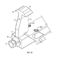
- FIG. 1 shows an exemplary solar mounting system 1 including at least one support column 2 , a torsion beam 3 connected to the support column 2 by a bearing 6 , a mounting rack (not shown) attached to the torsion beam 3 , and at least one photovoltaic module 5 mounted to the mounting system.
- An exemplary mounting bracket assembly 10 may be used to mount the mounting rack 4 to the torsion beam 3 .
- the torsion beam 3 may be any shape, including but not limited to, round, square, hexagonal, or any hybrid shape such as rounded with flats on one or more sides.
- One of the advantages of the disclosed embodiments is the ability of the mounting bracket to securely connect to a round or rounded tube using a single bolt, the threaded rod discussed herein.
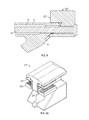
- the torsion beam can be a tube having a lock seam feature 54 , as illustrated in FIG. 15 .
- the mounting bracket assembly defines a beam insertion aperture 28 such that the torsion beam 3 may be disposed therein and run through the aperture.
- An exemplary mounting bracket assembly 10 comprises a body 12 or structural piece that may be made in whole or in part of a flexible or semi-flexible material.
- the flexible body 12 includes at least one top member 14 and an angled bottom member 16 connected to the top member 14 at opposite ends 18 , 20 thereof.
- the top member 14 and/or bottom member 16 may be made of a flexible or semi-flexible material.
- the angled bottom member 16 may be fixedly attached to the top member 14 or the body 12 may be a unitary structure made by machining, extrusion, casting, molding, of cast aluminum, extruded aluminum, injection molded plastic, or could be made of steel, fiberglass, composite, or any other strong flexible or semi-flexible material.
- the angle of the bottom member 16 may vary as seen in the embodiments of FIGS. 4A-4C and 5A-5C .
- a network of strengthening members 17 may be provided between the top member 14 and the angled bottom member 16 .
- the body 12 includes a ring 44 that defines a beam insertion aperture 28 between the top member 14 and the bottom member 16 .
- the beam insertion aperture may be of any size or shape depending on the size and shape of the torsion beam 3 being inserted therethrough, including but not limited to, round, square, hexagonal, or any hybrid shape such as rounded with flats on one or more sides.
- the size of the ring 44 and the beam insertion aperture 28 may vary depending on the application, as seen in the embodiments of FIGS. 4A-4C and 5A-5C .
- the mounting bracket assembly 10 is advantageously designed so it has structural material only where necessary and is in the shape and form of the stresses on the assembly.
- the body 12 of the mounting bracket assembly 10 could have a two-piece construction.
- FIGS. 20, 20A -B, and 21 A-B illustrate embodiments in which body 12 comprises two attachable body pieces 12 a and 12 b . This advantageously facilitates attachment of the mounting bracket assembly 10 to the torsion beam 3 .
- the body pieces could be joined by a slidable locking mechanism 13 comprising a mating flange 15 and groove 17 , as seen FIGS. 20A and 20B .
- a hinged connection 19 including a hinge pin 21 could be provided.
- At least one clamp 22 is attached to an end 18 , 20 of the top member 14 and in exemplary embodiments, a first clamp 22 a is attached a first end 18 of the top member 14 and a second clamp 22 b is attached to the second end 20 of the top member 14 .
- An exemplary clamp 22 has an arm 24 and a flange 26 .
- the arm 24 and flange 26 of the clamps 22 a , 22 b serve to attach to the top or side of a frame 23 of a PV module 5 to hold the module in place.
- Clamps 22 may also be compression style securing the PV module by compression or use hooks to attach to the sides of the PV module.
- the mounting bracket assembly 10 and clamps 22 may vary in length for different module designs and load requirements. Clamps 22 could also define an additional hole for driving a screw or other fastener through the clamp and a cutout in module frame to further secure a PV module.
- clamps 222 could include a substantially flat hard stop 227 for clamping the frameless PV modules.
- an exemplary clamp 222 for frameless modules could feature a substantially flat hard stop 227 for securing a frameless PV module in a press fit. This advantageously provides the ability to tighten more on the torsion tube 3 , not the module 5 .
- clamp 322 could include a flexible insert component 329 having serrated teeth 331 for gripping and securing the glass or other substrate of a frameless PV module.
- the mounting bracket assembly 10 includes an integral grounding device 30 capable of both securing and grounding an electricity generating device.
- An exemplary integral grounding device is grounding block 30 , which could take several forms, such as a block with a cross-shaped or U-shaped cross section.
- An exemplary embodiment of a grounding block 30 is a component of stainless steel or other conductive material strong enough to pierce both the frame of a PV module and a torsion beam to create a grounded connection.
- FIGS. 4B, 5B and 6-7 An exemplary arrangement of a grounding block 30 in a mounting bracket assembly 10 is illustrated in FIGS. 4B, 5B and 6-7 .
- the top member 14 of the body 12 may comprise two top members 14 a , 14 b lined up to form the full top member 14 of the body 12 of the mounting bracket assembly 10 .
- the grounding block 30 shown here as a conductive metal component, is disposed adjacent each top member 14 a , 14 b . More particularly, the grounding block is disposed in the center of the full top member 14 between top members 14 a and 14 b .
- This configuration advantageously provides grounding block 30 at a location where it can create a grounded connection between a mounted electricity generating device such as a PV module and a structural component such as a torsion beam of a mounting assembly.
- an integral grounding device 430 is illustrated in more detail.
- the integral grounding device 430 could include a locating pin 429 to index a PV module.
- An exemplary embodiment of a mounting bracket assembly 10 includes at least one module locating pin 429 and a grounding block 30 disposed in the center of the top member 14 between top members 14 a and 14 b .
- Another exemplary embodiment uses at least one module locating pin 429 (e.g., first and second locating pins 429 a and 429 b ) with a grounding washer 433 to secure the locating pin 429 to the top member 14 and provide a grounding connection to the PV module 5 .
- at least one spined grounding barb 431 e.g., first and second barbs 431 a and 431 b
- the spined grounding barb 431 serves to secure and ground the PV module 5 and obviates the need for a grounding washer or grounding block.
- the grounding block 30 serves to provide a secure grounding connection between the electricity generating devices such as PV modules 5 and the torsion beam 3 to which the mounting bracket assemblies 10 are attached.
- the locating pins 429 a , 429 b also enable attachment and locking of the PV modules 5 to the mounting assembly.
- the locating pins 429 are advantageous for locating and locking in the modules, and could be serrated to gouge into the modules.
- the locating pin could also be a hooked component that indexes off the seam.
- the mounting bracket assembly 10 further comprises a threaded rod 32 running through the top member 14 . More particularly, the rod 32 runs through first clamp 22 a , first top member 14 a , grounding block 30 , second top member 14 b , and second clamp 22 b . As best seen in FIG. 7 , an exemplary grounding block 30 may define a through hole 34 to facilitate the passage of rod 32 . A clamping nut 36 is also provided. Together with the clamping nut 36 , rod 32 serves to hold together the clamps, top members and grounding block. As shown in FIGS.
- the bolt head 43 may be designed to enable turning or rotating the threaded rod 32 to adjust the mating angles of the clamps 22 a , 22 b on the first end 18 of the top member 14 a , as described herein, or shaped so it cannot be rotated.
- Clamping nut 36 advantageously facilitates attachment and grounding of electricity generating devices such as PV modules. More particularly, rotation of the clamping nut 36 inward on the rod 32 compresses the top members 12 a , 12 b and moves the grounding block 30 such it secures and grounds the electricity generating device through contact or piercing the electricity generating device and the torsion beam.
- the clamping nut 36 may include a break-away component 37 that breaks off the permanently attached component 39 at the proper level of torque.
- the break-away component 37 could be designed to break off when one or more of the following conditions are met: the PV module 5 is secured by the clamps 22 , the module pressure has sufficient pressure on its ground points to achieve a good ground, and/or the mounting bracket assembly 10 has sufficient gripping force to be secured to the torsion beam 3 such that it will not rotate or slide on the beam under the load.
- the break-away feature could function as a torque quality assurance mechanism as well as having security hardware for an anti-theft system, which includes an anti-theft shaped nut 41 keyed to be removable.
- an alternative embodiment of a clamping nut 136 could have a removable component 137 that can be removed (without breaking) from the permanently attached component 139 .
- FIGS. 22, 23A and 23B another exemplary embodiment employs a cam-over device 52 at the end of threaded rod 32 to provide a quick-release mechanism.
- the cam-over device 52 has a disengaged position in which the handle portion 54 is extended straight and an engaged position in which the handle portion 54 is folded downward perpendicular to the threaded rod 32 .
- the cam-over device 52 can be rotated to secure it to the end of the threaded rod 32 and to the clamp 22 of the mounting bracket assembly 10 .
- the handle portion 54 of the cam-over device 52 may be folded downward to engage the quick-release mechanism. Once engaged, switching the handle portion 54 of the cam-over device 52 into the straight disengaged position quickly releases the device from the threaded rod 32 .
- FIGS. 24A-24G an exemplary embodiment of a mounting bracket assembly for use in high-load applications will now be described.
- the mounting bracket is designed so it can withstand high loads. More particularly, it is formed from two attachable bracket or frame pieces and two clamps connected by three fasteners so load forces can be dispersed and released from the mounting bracket at various connection points.
- One such application is in a solar mounting and/or tracking system for high loads.
- FIG. 24G shows an exemplary solar mounting system 101 including at least one support column 102 , a torsion beam 103 connected to the support column 102 by a bearing 106 , and at least one photovoltaic module 105 mounted to the mounting system.
- An exemplary mounting bracket assembly 110 may be used to mount the photovoltaic module 105 to the torsion beam 103 .
- the torsion beam 103 may be any shape, including but not limited to, round, square, hexagonal, octagonal, or any hybrid shape such as rounded with flats or grooves on one or more sides.
- the mounting bracket assembly 110 defines a beam insertion aperture 128 such that the torsion beam 103 may be disposed therein and run through the aperture.
- An exemplary mounting bracket assembly 110 comprises a mounting bracket 112 , which may be made, at least in part, of a rigid material, a flexible material, or a semi-flexible material.
- the mounting bracket 112 is comprised of two attachable bracket pieces 113 a , 113 b , with each piece having a top member 114 a , 114 b , a bottom member 116 a , 116 b , and half a ring 144 that, joined with the other half ring, forms a beam insertion aperture 128 .
- the bottom member 116 a of the first attachable bracket piece 113 a joins the top member 114 a at an angle A.
- the bottom member 116 b of the second attachable bracket piece 113 b joins the top member 114 b at the same angle A.
- the bottom members 116 a , 116 b may be fixedly attached to the top members 114 a , 114 b , or the bracket piece 112 may be a unitary structure made by machining, extrusion, casting, molding of cast aluminum, extruded aluminum, injection molded plastic, or could be made of steel, fiberglass, composite, or any other strong rigid, flexible, or semi-flexible material.
- One or more strengthening members 111 may be provided between the top members 114 a , 114 b and the bottom members 116 a , 116 b . When fully assembled, the top members 114 a , 114 b together extend about 22-24 mm and the full mounting bracket assembly 110 extends about 24-27 mm.
- the two bracket pieces 113 a , 113 b can be connected and secured together by any suitable fastening mechanism.
- fastener 125 c secures the bottom member 116 a of the first attachable bracket piece 113 a to the bottom member 116 b of the second attachable bracket piece 113 b .
- the top member 114 a of the first bracket piece 113 a may be attached to the top member 114 b of the second bracket piece 113 b by a locking mechanism 107 comprised of a curved mating flange 115 defining a hollow cylinder 117 , which receives a sliding mating section of the second bracket piece 113 b , whereby it is held from sliding apart by a blind rivet and a washer 121 , a mechanism shown in detail in FIG. 26F .
- a slidable locking mechanism as shown in FIGS. 20A and 20B , or a hinged connection with a hinge pin, as shown FIGS. 21A and 21B , could be used.
- the ring 144 defines a beam insertion aperture 128 between the top members 114 a , 114 b and the bottom members 116 a , 116 b of the mounting bracket 112 .
- the beam insertion aperture 128 may have an octagonal shape such that a torsion beam having an octagonal cross section may be inserted through the aperture 128 .
- the beam insertion aperture 128 may be of any size or shape depending on the size and shape of the torsion beam, including but not limited to, round, square, hexagonal, octagonal, or any hybrid shape such as rounded with flats on one or more sides. Moreover, the size of the ring 144 and the beam insertion aperture 128 may vary depending on the application.
- a clamp 122 is attached to an end portion 118 , 120 of each top member 114 a , 114 b of the bracket pieces 113 a , 113 b . More particularly, first clamp 122 a is attached to the top member 114 a of the first attachable bracket piece 113 a by first fastener 125 a , and second clamp 122 b is attached to the top member 114 b of the second attachable bracket piece 113 b by second fastener 125 b . As discussed above, a third fastener 125 c serves to secure the first and second bracket pieces 113 a , 113 b .
- the fasteners 125 a , 125 b , 125 c can be any suitable fastening devices or assemblies, and in exemplary embodiments each fastener is comprised of a carriage bolt, a nut, and one or more washers, as needed.
- An exemplary mounting bracket assembly utilizing three fasteners may use one fastener to clamp the bracket around the torque tube, while utilizing the other two fasteners, one each located at the end portion of the top member, disposed perpendicular to the top member of the bracket.
- the two perpendicular fasteners may be inserted through a hole in a U-shaped clamp member such that when the fasteners are tightened, the U-shaped clamps provide pressure on the electric generating device to securely clamp it to the top member of the mounting bracket assembly.
- one or both clamps 122 a , 122 b may have an angled mating surface 138 that corresponds with an angled surface 140 of the first end portion 118 , 120 of each respective top member 114 a , 114 b of the bracket pieces 113 a , 113 b .
- one or both clamps 122 a , 122 b may have an upwardly extending arm 124 and a flange 126 at a distal end of the arm. The arm 124 and flange 126 of the clamps 122 a , 122 b serve to attach to the top or side of a frame 123 of a PV module 105 to hold the module in place.
- Clamps 122 may also be compression style securing the PV module by compression or use hooks to attach to the sides of the PV module.
- the mounting bracket assembly 110 and clamps 122 may vary in length for different module designs and load requirements.
- Clamps 122 could also define an additional hole for driving a screw or other fastener through the clamp and a cutout in module frame to further secure a PV module.
- the mounting bracket assembly 110 includes a first integral grounding device 130 a configured to electrically bond a frame of an electricity generating device to the mounting bracket assembly.
- An exemplary grounding device is a grounding strip 130 , which could vary in shape and size and could be either one- or two-sided.
- the grounding strip 130 is made of stainless steel or other conductive material strong enough to pierce the frame of a PV module and create a grounded connection.
- the first grounding strip 130 a may be located adjacent to one of the top members 114 a , 114 b of the first or second attachable bracket piece 113 a , 113 b .
- the first grounding strip 130 a is attached to an end portion 120 of the top member 114 b of the second bracket piece 113 b . More particularly, the first grounding strip 130 a could be located within the end portion 120 where the top member 114 b attaches to clamp 122 b.
- the mounting bracket assembly 110 may be designed to be used in corrosive environments.
- the mounting bracket may be treated to be corrosion-resistant. More particularly, the mounting bracket assembly 110 or components thereof may be treated to be corrosion-resistant and, if needed, additional integral grounding devices 130 b , 130 c provided.
- the mounting bracket 112 and/or the clamps 122 may have an anodized finish 141 , as best seen in FIG. 24F . This could be accomplished by an electrochemical process to increase the thickness of the natural oxide layer on the components such that the mounting bracket assembly 110 has a corrosion-resistant, anodic oxide finish. It should be noted that the mounting bracket assembly could be otherwise coated, painted, or provided with other conversion coatings so the aluminum part has a non-conductive surface layer.
- the corrosion-resistant coatings may be non-electrically conductive and therefore may need to be pierced for the mounting bracket assembly to provide conductivity.
- the mounting bracket assembly 110 may require at least two integral grounding devices and/or double grounding capability.
- FIG. 27 shows an exemplary one-way grounding strip 130 with grounding holes 131 protruding in a downward direction.
- a grounding strip 530 may provide double grounding capability. More particularly, the double ground strip 530 has both upward protruding grounding holes 533 and downward protruding grounding holes 531 .
- the mounting bracket assembly may include at least two integral grounding devices 130 a , 130 b . More particularly, as best seen in FIG.
- a second grounding strip 130 b may be attached to an end portion 120 of the top member 114 a of the first bracket piece 113 a or may be located elsewhere on the mounting bracket. In some embodiments, the second grounding strip 230 b may be at another location on the mounting bracket such as on a portion of the ring 244 , as shown in FIG. 25D .
- the first grounding strip 130 a electrically bonds the frame of the electricity generating device to the mounting bracket assembly 110 .
- the second grounding strip 230 b electrically bonds the mounting bracket assembly to the torsion beam 103 , thereby completing the electrical connection or ground path.
- a third integral grounding device 130 c may be located elsewhere on the mounting bracket such as on a portion of the ring 144 at or near the location where third fastener 125 c secures the first and second bracket pieces 113 a , 113 b , at or near the location where the locking mechanism connects the top member 114 a of the first bracket piece 113 a to the top member 114 b of the second bracket piece 113 b , or any other appropriate location on the mounting bracket 112 and/or the clamps 122 .
- the second grounding strip attached to an end portion 120 of the top member 114 a of the first bracket piece 113 a , also serves to electrically bond the frame of the electricity generating device to the mounting bracket assembly 110 .
- the third grounding strip 130 c electrically bonds the mounting bracket assembly to the torsion beam 103 , thereby completing the electrical connection or ground path.
- One, two, or all three of the grounding strips 130 a , 130 b , 130 c may be double-sided. It also should be noted that more than three grounding devices could be included in the mounting bracket assembly if needed.
- an exemplary embodiment of a mounting bracket assembly 210 for ordinary load applications comprises a mounting bracket 212 which can be made in whole or in part of a rigid, flexible, or semi-flexible material.
- the mounting bracket 212 is comprised of a bottom member 216 and at least one top member 214 .
- the mounting bracket 212 has two top members 214 a , 214 b which extend from the corners of the mounting bracket 212 toward the center. As shown in FIGS. 25A and 25B , the two top members 214 a , 214 b extend partially across the mounting bracket 212 and instead of meeting, they leave a gap 227 .
- the two top members 214 a , 214 b could meet, or the mounting bracket 212 could have a single top member 214 extending across the full length of the mounting bracket.
- the bottom member 216 of the mounting bracket 212 joins top member 214 a at an angle A and top member 214 b at the same angle A.
- the bottom member 216 may be fixedly attached to the top members 214 a , 214 b , or the mounting bracket 212 may be a unitary structure made by machining, extrusion, casting, molding of cast aluminum, extruded aluminum, injection molded plastic, or could be made of steel, fiberglass, composite, or any other strong flexible or semi-flexible material.
- the mounting bracket 212 includes a ring 244 that defines a beam insertion aperture 228 between the top members 214 a , 214 b and the bottom member 216 .
- the beam insertion aperture 228 is octagonal in shape to receive a torsion beam having an octagonal cross section.
- the beam insertion aperture 228 may be of any size or shape depending on the size and shape of the torsion beam, including but not limited to, round, square, hexagonal, octagonal, or any hybrid shape such as rounded with flats on one or more sides.
- the size of the ring 244 and the beam insertion aperture 228 may vary depending on the application.
- a threaded rod 232 (discussed in detail herein) runs parallel to the top members 214 a , 214 b over the gap 227 and forming the top of the octagonal ring 244 .
- At least one clamp 222 is attached to an end portion 218 , 220 of each top member 214 a , 214 b of the mounting bracket 212 . More particularly, first clamp 222 a is attached to the first top member 214 a of the mounting bracket 212 and second clamp 222 b is attached to the second top member 214 b of the mounting bracket 212 . With the clamps 222 b , the mounting bracket assembly 210 is about 12-15 mm long at its longest point.
- one or both clamps 222 a , 222 b may have an angled mating surface 238 that corresponds with an angled surface 240 of the first and second end portion 218 , 220 of each respective top member 214 a , 214 b of the mounting bracket 212 .
- one or both clamps 222 a , 222 b may have an upwardly extending arm 224 and a flange 226 at a distal end of the arm. The arm 224 and flange 226 of the clamps 222 a , 222 b serve to attach to the top or side of a frame 123 of a PV module 105 to hold the module in place.
- Clamps 222 may also be compression style, securing the PV module by compression or use hooks to attach to the sides of the PV module.
- the mounting bracket assembly 210 and clamps 222 may vary in length for different module designs and load requirements.
- Clamps 222 could also define an additional hole for driving a screw or other fastener through the clamp and a cutout in module frame to further secure a PV module.
- the mounting bracket assembly 210 includes at least one integral grounding device 230 configured to secure and electrically ground an electricity generating device.
- An exemplary grounding device is a grounding strip 230 , which could vary in shape and size.
- the grounding strip 230 is made of stainless steel or other conductive material strong enough to pierce the frame of a PV module and create a grounded connection.
- the grounding strip 230 may be located adjacent to one of the top members 214 a , 214 b of the bracket piece 212 .
- the grounding strip 230 is attached to an end portion 220 of the top member 214 b of the second bracket piece 212 . More particularly, the grounding strip 230 could located with the end portion 220 where the top member 214 b attaches to clamp 222 b.
- mounting bracket assembly 210 further comprises a threaded rod 232 running through the top members 214 a , 214 b . More particularly, the rod 232 runs through first clamp 222 a , runs parallel to and on top of first top member 214 a and second top member 214 b , and run through second clamp 222 b .
- a clamping nut 236 is also provided. Together with the clamping nut 236 , rod 232 serves to hold together the clamps and top members of the mounting bracket.
- the portion of the threaded rod 232 that runs over the gap 227 may serve as the top of octagonal ring 244 due to its orientation parallel to the top members 214 a , 214 b and position over the gap 227 .
- a bolt head 243 may be designed to enable turning or rotating the threaded rod 232 to adjust the mating angles of the clamps 222 a , 222 b on the first end 218 of the top member 214 a , as described herein, or shaped so it cannot be rotated.
- Clamping nut 236 advantageously secures the mounting bracket assembly 210 to a torsion beam and facilitates attachment and grounding of electricity generating devices such as PV modules. More particularly, rotation of the clamping nut 236 inward on the rod 232 compresses the top members 214 a , 214 b and compresses the grounding strip 230 such that it electrically grounds the electricity generating device by compressing the mating frame of the electricity generating device.
- an exemplary mounting bracket assembly may utilize a double ground device as shown in FIG. 28 .
- the mounting bracket assembly 210 may include at least two integral grounding devices 230 a , 230 b . More particularly, as illustrated in FIG. 25D , a second grounding strip 230 b may be attached to the ring 144 or may be located elsewhere on the mounting bracket. A third integral grounding device, or grounding strip, may be located elsewhere on the mounting bracket, and additional grounding devices may be provided as well.
- FIGS. 26A-26C illustrate an exemplary embodiment of a two-piece mounting bracket assembly 310 utilizing a threaded rod 332 and clamping nut 336 feature. This embodiment is significantly longer than the mounting bracket shown in FIGS. 25A-25C , having a length of about 21-24 mm along its two top members 314 a , 314 b and about 24-26 mm including the clamps 322 a , 322 b .
- the mounting bracket assembly 310 comprises a mounting bracket 312 which can be made in whole or in part of a rigid, flexible, or semi-flexible material.
- the mounting bracket 312 is comprised of two attachable bracket pieces 313 a , 313 b , with each piece having a top member 314 a , 314 b , a bottom member 316 a , 316 b .
- the mounting bracket 312 has two top members 314 a , 314 b which extend from the corners of the mounting bracket 312 toward the center.
- the bottom member 316 a of the first bracket piece 313 a may be attached to the bottom member 316 b of the second bracket piece 313 b by a locking mechanism.
- an exemplary locking mechanism is comprised of a curved mating flange 115 defining a hollow cylinder 117 , which receives a sliding mating section of the second bracket piece 113 b , whereby it is held from sliding apart by a blind rivet and a washer 121 .
- the two top members 314 a , 314 b extend partially across the mounting bracket 312 and instead of meeting, they leave a gap 327 .
- Ring 344 which could be any shape and is shown as octagonal, defines a beam insertion aperture 328 between the top members 314 a , 314 b and the bottom member 316 .
- a network of strengthening members 317 may be provided between the top members 314 a , 314 b and the angled bottom member 316 .
- a first clamp 322 a is attached to the top member 314 a of the first bracket piece 313 a and a second clamp 322 b is attached to the top member 314 b of the second bracket piece 313 b .
- one or both clamps 322 a , 322 b may have an angled mating surface 338 that corresponds with an angled surface 340 of the first and second end portion 318 , 320 of each respective top member 314 a , 314 b of the bracket pieces 313 a , 313 b .
- one or both clamps 322 a , 322 b may have an upwardly extending arm 324 and a flange 326 at a distal end of the arm.
- the arm 324 and flange 326 of the clamps 322 a , 322 b serve to attach to the top or side of a frame of a PV module to hold the module in place.
- a grounding strip 330 is located adjacent to one of the top members 314 a , 314 b of the bracket pieces 313 a , 313 b .
- the grounding strip 330 is attached to an end portion 320 of the top member 314 b of the second bracket piece 313 b . More particularly, the grounding strip 330 could located with the end portion 320 where the top member 314 b attaches to clamp 322 b.
- mounting bracket assembly 310 further comprises a threaded rod 332 running through the top members 314 a , 314 b , through first clamp 322 a , parallel to and on top of first top member 314 a and second top member 314 b , and through second clamp 322 b . Together with a clamping nut 336 , rod 332 serves to hold together the clamps and top members of the mounting bracket.
- the portion of the threaded rod 332 that runs over the gap 327 may serve as the top of octagonal ring 344 due to its orientation parallel to the top members 314 a , 314 b and position over the gap 327 .
- bolt head 343 may be designed to enable turning or rotating the threaded rod 332 to adjust the mating angles of the clamps 322 a , 322 b on the first end 318 of the top member 314 a , as described herein, or shaped so it cannot be rotated.
- Clamping nut 336 secures the mounting bracket assembly 310 to a torsion beam and facilitates attachment and grounding of electricity generating devices such as PV modules.
- Exemplary embodiments advantageously provide mechanisms for adjusting the clamping force on the electricity generating device and the mounting system by adjusting the angles certain components of the mounting bracket assembly.
- clamp 22 , 122 , 222 , 322 may have an angled mating surface 38 , 138 , 238 , 338 , and the first end 18 , 118 , 218 , 318 and second end 20 , 120 , 220 , 320 of the top member 14 , 114 a , 114 b , 214 a , 214 b , 314 a , 314 b may each have a corresponding angled surface 40 , 140 , 240 , 340 .
- clamp 22 a , 122 a , 222 a , 322 a mates with the first end 18 , 118 , 218 , 318 of the top member 14 , 114 a , 214 a , 314 a such that the angled mating surface 38 , 138 , 238 , 338 is adjacent the corresponding angled surface 40 , 140 , 240 , 340 of the first end 18 , 118 , 218 , 320 of the top member 14 , 114 a , 214 a , 314 a .
- clamp 22 b , 122 b , 222 b , 322 b mates with the second end 20 , 120 , 220 , 320 of the top member 14 , 114 b , 214 b , 314 b such that the angled mating surface 38 , 138 , 238 , 338 is adjacent the corresponding angled surface 40 , 140 , 240 , 340 of the second end 20 , 120 , 220 , 320 of the top member 14 , 114 b , 214 b , 314 b.
- varying the defined mating angle 60 of either clamp 22 a and the first end 18 of the top member 14 or the defined mating angle 60 of clamp 22 b and the second end 20 of the top member 14 changes the gripping force of the mounting bracket assembly 10 on the torsion beam 3 running through the beam insertion aperture 28 . Also, varying the defined mating angle 60 of either clamp 22 a and the first end 18 of the top member 14 or the defined mating angle 60 of clamp 22 b and the second end 20 of the top member 14 changes the clamping force of the mounting bracket assembly 10 on the electricity generating device 5 .
- this ability to change angles permits the adjustment of clamping force on the electricity generating device, e.g., PV module, and on the mounting system structure and torsion beam as separate forces using only one fastener. It should be noted that the same principles, functions, and effects apply to the embodiments discussed in connection with FIGS. 24A-24E, 25A-25C, and 26A-26F .
- exemplary embodiments facilitate separation of the downward clamping force 56 exerted on the PV module 5 and the gripping force 58 exerted on the torsion beam 3 .
- This is accomplished by allowing the arm 24 of each clamp 22 a , 22 b to tighten to a physical stop, which results in the rest of the force in the threaded rod 32 to be directed into the gripping force 58 on the torsion beam.
- the clamp flanges 26 may also incorporate a spring design feature 48 , as shown in FIG. 14 , which allows the downward clamping force 56 exerted on the PV module 5 to remain constant even if there is thickness variance of the module frame or during temperature fluctuations.
- exemplary embodiments may include wire routing in the design, providing integral wire management capability through the clamps 22 .
- the mounting bracket 12 of the mounting bracket assembly 10 could be designed to include an additional wire aperture 50 at a suitable spot on the body.
- An exemplary embodiment has the wire aperture 50 in a corner of the mounting bracket 12 .
- wires 62 for transmission of electrical energy to a utility grid or off-grid load and/or to an inverter for current conversion can be conveniently run throughout the solar energy system and managed to some extent by movement of clamps 22 .
- a grommet 64 cold be provided to reduce tearing or abrasion on the wires.
- a mounting bracket assembly 10 , 110 , 201 , 310 is connected to a torsion beam 3 of a solar mounting system 1 such that the torsion beam 3 runs through the beam insertion aperture 28 defined in the body 12 of the assembly.
- This connection could be achieved by sliding the torsion beam 3 through the beam insertion aperture 28 or by opening the body 12 of the mounting bracket assembly such that a gap 42 is formed in the ring 44 of the beam insertion aperture 28 and pressing torsion beam 3 through gap 42 into the aperture 28 .
- the grounding block 30 is then inserted between first and second top members 14 a , 14 b.
- One or more clamps 22 are attached to one or both ends 18 , 20 of the full top member 12 , particularly, a first clamp 22 a is attached a first end 18 of the top member 12 and a second clamp 22 b is attached to the second end 20 of the top member 12 . Then a threaded rod 32 is inserted through first clamp 22 a , first top member 12 a , grounding block 30 , second top member 12 b , and second clamp 22 b and secured with a clamping nut 36 .
- One or more PV modules 5 are mounted to a mounting rack 4 and the arm 24 and flange 26 of the clamps 22 a , 22 b are attached to the top or side of the PV modules to hold them in place.
- the system can be further secured and the PV modules 5 grounded by tightening the clamping nut 36 on the threaded rod 32 running through the top member 12 . More particularly, the clamping nut 36 is rotated inward on the rod 32 , which tightens the mounting bracket assembly 10 . The rotation of clamping nut 36 presses first clamp 22 a into first top member 12 a and compresses the second top member 12 b and second clamp 22 b . This compression moves the grounding block 30 such it secures and grounds the electricity generating device through contact or piercing the electricity generating device and the torsion beam.
- the manufacturer can take just one step—the rotation of the clamping nut 36 —to compress the entire mounting bracket assembly 10 , simultaneously grounding and attaching the PV module 5 .
- the clamping nut 36 may break off when the grounding block 30 secures and grounds the electricity generating device and/or when the desired torque is achieved. Once assembled and tightened as described, the geometry and/or friction of the mounting bracket assembly 10 keep it from rotating.
- the manufacturer can adjust the clamping force 56 on the one or more PV modules and/or the gripping force 58 on the mounting system as needed by changing the angles of certain components of the mounting bracket assembly. More particularly, the manufacturer may change the mating angle 60 of clamp 22 a on the first end 18 of the top member 14 a and/or the mating angle 60 of clamp 22 b on the second end 20 of the top member 14 b . The manufacturer can vary the clamping force by loosening or tightening the clamp bolt 46 on clamp 22 b or loosening or tightening the clamping nut 36 on clamp 22 a .
- the manufacturer can change the gripping force 58 of the mounting bracket assembly 10 on the torsion beam 3 running through the beam insertion aperture 28 and/or the clamping force 56 of the mounting bracket assembly 10 on the one or more photovoltaic modules 5 .
- this ability to change angles permits the adjustment of clamping force on the electricity generating device, e.g., PV module, and on the mounting system structure and torsion beam as separate forces using only one fastener.
- the PV module frames may have self-centering and locking features.
Landscapes
- Engineering & Computer Science (AREA)
- Life Sciences & Earth Sciences (AREA)
- Sustainable Development (AREA)
- Chemical & Material Sciences (AREA)
- Physics & Mathematics (AREA)
- Sustainable Energy (AREA)
- Thermal Sciences (AREA)
- Combustion & Propulsion (AREA)
- Mechanical Engineering (AREA)
- General Engineering & Computer Science (AREA)
- Structural Engineering (AREA)
- Civil Engineering (AREA)
- Architecture (AREA)
- Clamps And Clips (AREA)
Abstract
Description
Claims (20)
Priority Applications (15)
| Application Number | Priority Date | Filing Date | Title |
|---|---|---|---|
| US15/063,098 US10069455B2 (en) | 2013-10-02 | 2016-03-07 | Mounting bracket assemblies and methods |
| KR1020187026082A KR102265933B1 (en) | 2016-03-07 | 2017-03-03 | Mounting Bracket Assemblies and Methods |
| EP17763779.0A EP3426934B1 (en) | 2016-03-07 | 2017-03-03 | Mounting bracket assemblies and methods |
| MX2018010786A MX2018010786A (en) | 2016-03-07 | 2017-03-03 | ASSEMBLY ASSEMBLIES AND METHODS. |
| PL17763779T PL3426934T3 (en) | 2016-03-07 | 2017-03-03 | Mounting bracket assemblies and methods |
| DK17763779.0T DK3426934T3 (en) | 2016-03-07 | 2017-03-03 | Mounting devices and methods |
| JP2018544559A JP7118005B2 (en) | 2016-03-07 | 2017-03-03 | Mounting bracket assembly and method |
| BR112018067844-9A BR112018067844B1 (en) | 2016-03-07 | 2017-03-03 | MOUNTING SUPPORT SET AND MOUNTING SET |
| PT17763779T PT3426934T (en) | 2016-03-07 | 2017-03-03 | Mounting bracket assemblies and methods |
| AU2017228903A AU2017228903A1 (en) | 2016-03-07 | 2017-03-03 | Mounting bracket assemblies and methods |
| ES17763779T ES2892099T3 (en) | 2016-03-07 | 2017-03-03 | Mounting Bracket Assemblies and Procedures |
| PCT/US2017/020558 WO2017155798A1 (en) | 2016-03-07 | 2017-03-03 | Mounting bracket assemblies and methods |
| CN201780015520.1A CN108700097B (en) | 2016-03-07 | 2017-03-03 | Mounting Bracket Assembly and Method |
| ZA2018/05516A ZA201805516B (en) | 2016-03-07 | 2018-08-17 | Mounting bracket assemblies and methods |
| MX2024009885A MX2024009885A (en) | 2016-03-07 | 2018-09-06 | Mounting bracket assemblies and methods |
Applications Claiming Priority (2)
| Application Number | Priority Date | Filing Date | Title |
|---|---|---|---|
| US14/044,704 US9281778B2 (en) | 2013-10-02 | 2013-10-02 | Mounting bracket assemblies and methods |
| US15/063,098 US10069455B2 (en) | 2013-10-02 | 2016-03-07 | Mounting bracket assemblies and methods |
Related Parent Applications (1)
| Application Number | Title | Priority Date | Filing Date |
|---|---|---|---|
| US14/044,704 Continuation-In-Part US9281778B2 (en) | 2013-10-02 | 2013-10-02 | Mounting bracket assemblies and methods |
Publications (2)
| Publication Number | Publication Date |
|---|---|
| US20160190976A1 US20160190976A1 (en) | 2016-06-30 |
| US10069455B2 true US10069455B2 (en) | 2018-09-04 |
Family
ID=56165470
Family Applications (1)
| Application Number | Title | Priority Date | Filing Date |
|---|---|---|---|
| US15/063,098 Active 2034-06-16 US10069455B2 (en) | 2013-10-02 | 2016-03-07 | Mounting bracket assemblies and methods |
Country Status (1)
| Country | Link |
|---|---|
| US (1) | US10069455B2 (en) |
Cited By (24)
| Publication number | Priority date | Publication date | Assignee | Title |
|---|---|---|---|---|
| US10355636B2 (en) * | 2016-07-21 | 2019-07-16 | Everest Solar Systems Llc | Structure and support device for photovoltaic arrays |
| USD905626S1 (en) * | 2019-07-25 | 2020-12-22 | Nextracker Inc. | Panel rail saddle for solar module |
| WO2021226563A1 (en) * | 2020-05-08 | 2021-11-11 | Array Technologies, Inc. | Mounting bracket |
| USD940547S1 (en) | 2019-12-13 | 2022-01-11 | Array Technologies, Inc. | Clamp |
| US11228275B2 (en) | 2019-06-27 | 2022-01-18 | National Oilwell Vareo, L.P. | Methods and apparatus for installing solar panels |
| US11258397B2 (en) * | 2020-02-11 | 2022-02-22 | Ap Alternatives, Llc | Solar module mounting system |
| US20220103116A1 (en) * | 2020-09-29 | 2022-03-31 | Ojjo, Inc. | Braced truss foundations for single-axis trackers and related systems and methods |
| US11360492B2 (en) | 2019-10-02 | 2022-06-14 | Array Technologies, Inc. | Solar tracking system |
| USD956538S1 (en) | 2020-05-08 | 2022-07-05 | Array Technologies, Inc. | Mounting hardware |
| USD956536S1 (en) | 2020-05-08 | 2022-07-05 | Array Technologies, Inc. | Mounting hardware |
| USD956537S1 (en) | 2020-05-08 | 2022-07-05 | Array Technologies, Inc. | Mounting hardware |
| EP4073925A1 (en) | 2019-12-13 | 2022-10-19 | Array Technologies, Inc. | Modified clamp |
| US11527988B2 (en) | 2020-05-13 | 2022-12-13 | Array Technologies, Inc. | Mounting bracket extension |
| US11563402B2 (en) * | 2016-06-12 | 2023-01-24 | Array Technologies, Inc. | Clip-on mounting rails, mounting brackets, and methods of mounting solar modules |
| US11569780B2 (en) * | 2020-03-17 | 2023-01-31 | Sun And Steel Solar Llc | Purlin system for solar module attachment |
| USD987421S1 (en) * | 2020-12-11 | 2023-05-30 | Array Technologies, Inc. | Clamp |
| US11811358B2 (en) | 2020-02-11 | 2023-11-07 | Apa Solar, Llc | Solar module mounting system |
| US20240039459A1 (en) * | 2022-08-01 | 2024-02-01 | Array Technologies, Inc. | Photovoltaic module mount |
| US20250023508A1 (en) * | 2023-07-10 | 2025-01-16 | Array Technologies, Inc. | Mounting rails |
| USD1083770S1 (en) * | 2023-05-22 | 2025-07-15 | Nextracker Llc | Panel rail saddle for solar module |
| USD1090414S1 (en) * | 2023-05-22 | 2025-08-26 | Nextracker Llc | Panel rail saddle for solar module |
| USD1094260S1 (en) * | 2023-05-22 | 2025-09-23 | Nextracker Llc | Panel rail saddle for solar module |
| USD1100809S1 (en) * | 2023-05-22 | 2025-11-04 | Nextracker Llc | Panel rail saddle for solar module |
| USD1107642S1 (en) * | 2023-05-22 | 2025-12-30 | Nextracker Llc | Panel rail saddle for solar module |
Families Citing this family (21)
| Publication number | Priority date | Publication date | Assignee | Title |
|---|---|---|---|---|
| US10069455B2 (en) * | 2013-10-02 | 2018-09-04 | Array Technologies, Inc. | Mounting bracket assemblies and methods |
| EP3426934B1 (en) * | 2016-03-07 | 2021-07-07 | Array Technologies, Inc. | Mounting bracket assemblies and methods |
| CN107248836B (en) * | 2017-04-14 | 2020-01-21 | 张宇顺 | Annular solar panel support and annular solar panel power generation device |
| WO2019058165A1 (en) | 2017-09-19 | 2019-03-28 | Helioslite | SOLAR MODULE ASSEMBLY ASSEMBLY |
| US11283395B2 (en) | 2018-03-23 | 2022-03-22 | Nextracker Inc. | Multiple actuator system for solar tracker |
| US11387771B2 (en) | 2018-06-07 | 2022-07-12 | Nextracker Llc | Helical actuator system for solar tracker |
| US10797635B2 (en) * | 2018-08-29 | 2020-10-06 | Nextracker Inc. | Solar module mounting bracket assemblies |
| US11050383B2 (en) | 2019-05-21 | 2021-06-29 | Nextracker Inc | Radial cam helix with 0 degree stow for solar tracker |
| US10801755B1 (en) * | 2019-05-31 | 2020-10-13 | Nemat, Inc. | Apparatuses and methods for simplified installation of solar panels |
| CN110469065B (en) * | 2019-09-18 | 2024-10-18 | 正泰新能科技股份有限公司 | A photovoltaic module |
| US11078661B2 (en) * | 2019-10-04 | 2021-08-03 | Timothy William Canby | Rolling block restraint connector having an improved linkage assembly |
| ES1243445Y (en) * | 2019-12-18 | 2020-08-28 | Soltec Innovations Sl | SELF-SUPPORTING FRAME FOR PHOTOVOLTAIC PANELS |
| US11296649B2 (en) | 2020-02-07 | 2022-04-05 | National Oilwell Varco, L.P. | Foldable solar panel assembly |
| US12152809B2 (en) * | 2022-08-15 | 2024-11-26 | Terabase Energy, Inc. | Solar table clamp |
| US20240146233A1 (en) * | 2022-11-01 | 2024-05-02 | Todd Allen Myers | Panel Clamp Assembly |
| US20240235470A1 (en) | 2023-01-09 | 2024-07-11 | Sarcos Corp. | Auto-Engaging Electrical Connections for Solar Panels |
| US12466066B2 (en) | 2023-05-04 | 2025-11-11 | Sarcos Corp. | Solar panel dispensing device with vertical solar panel hopper loading and dispensing |
| WO2025111182A1 (en) * | 2023-11-21 | 2025-05-30 | Nextracker Llc | In-situ solar tracker manufacturing |
| US20250224148A1 (en) * | 2024-01-08 | 2025-07-10 | Sarcos Corp. | Solar Panel Installation Alignment Systems |
| US12570001B2 (en) | 2024-01-08 | 2026-03-10 | Sarcos Corp. | Support clamp installation vehicles as part of a solar panel installation system for a solar tracking system |
| US12542513B2 (en) | 2024-01-08 | 2026-02-03 | Sarcos Corp. | Torque tube clamps for automated solar panel installation |
Citations (39)
| Publication number | Priority date | Publication date | Assignee | Title |
|---|---|---|---|---|
| US704957A (en) | 1902-03-15 | 1902-07-15 | William F Kean | Bracket for subsidiary shelving. |
| US1832315A (en) | 1930-10-25 | 1931-11-17 | Mcnulty Alexis Copp | Supporting device |
| US2675201A (en) | 1948-09-22 | 1954-04-13 | Friel Patrick | Beam attachment clamp |
| US3026368A (en) | 1959-03-10 | 1962-03-20 | L E Lindsey | Conductor clamp assembly for use on pole top insulators |
| US3698691A (en) | 1971-06-16 | 1972-10-17 | Thomas W Brown | Fence barb arm |
| US4019705A (en) | 1972-04-05 | 1977-04-26 | Habuda Sr Blair A | Pipe hanging apparatus |
| US4065218A (en) | 1976-11-10 | 1977-12-27 | Super Strut, Inc. | Seismic brace |
| US4089276A (en) | 1977-04-08 | 1978-05-16 | Enos Ernest S | Portable bumper platform |
| US4371139A (en) | 1979-12-31 | 1983-02-01 | Sunsearch, Inc. | Adjustable mounting rack for solar collectors |
| DE8520407U1 (en) | 1985-07-15 | 1985-09-26 | Siemens AG, 1000 Berlin und 8000 München | Holding device for a number of panels that are equipped with solar cells |
| US5863020A (en) | 1995-11-01 | 1999-01-26 | Rose Manufacturing Company | Lifeline mounting apparatus |
| DE10025538A1 (en) | 2000-05-23 | 2001-11-29 | Walter Juergens | Solar mounting block |
| US20020070317A1 (en) | 2000-03-11 | 2002-06-13 | Goodman William Max | Cable clamp |
| DE20319065U1 (en) | 2003-12-09 | 2004-02-26 | Phönix SonnenStrom AG | Support frame for use with solar energy panels is hinged onto a carrier on ground installed pillars |
| US20060138286A1 (en) | 2004-12-29 | 2006-06-29 | Connolly Michael J | Pipe hanger assembly |
| KR200429997Y1 (en) | 2006-08-21 | 2006-11-02 | 김진곤 | Installation port for constructing fish beam work |
| WO2008084102A2 (en) | 2007-01-12 | 2008-07-17 | Paul Schlossbauer | Device comprising a plurality of supporting framework modules, and mechanism for adjusting modules used for converting or concentrating solar power |
| US7472876B2 (en) | 2006-07-21 | 2009-01-06 | Jones Thomas M | Bracket system |
| US20100089389A1 (en) | 2008-10-13 | 2010-04-15 | Sunlink, Corp. | Solar Array Mounting System with Universal Clamp |
| KR20100119275A (en) | 2009-04-30 | 2010-11-09 | (주)베이스테크 | Apparatus for supporting concrete formwork of crossbeam |
| US20110073105A1 (en) | 2009-09-25 | 2011-03-31 | Waterco Limited | Modular thermal water solar panel system |
| US20110253190A1 (en) | 2010-04-15 | 2011-10-20 | Daetwyler-Clean Energy LLC | Solar panel mounting bracket and solar panel mounting system |
| US20110283492A1 (en) | 2008-05-22 | 2011-11-24 | Mcpheeters Greg | Universal End Clamp |
| US20120240489A1 (en) | 2011-03-24 | 2012-09-27 | Rivera Angel M | Flat roof solar racking system |
| DE102011106083A1 (en) | 2011-06-08 | 2012-12-13 | Schletter Gmbh | Stand for PV modules |
| US20130061909A1 (en) | 2009-10-13 | 2013-03-14 | Claude Jacquot | Device shaped so that it can be used alone to secure a solar panel to a single beam of a support structure, and unit comprising one such device |
| US8413944B2 (en) | 2009-05-01 | 2013-04-09 | Applied Energy Technologies | Mounting systems for solar panels |
| US20130153519A1 (en) | 2010-06-24 | 2013-06-20 | Erryn Ashmore | Modular Solar Support Assembly |
| JP2013527991A (en) | 2010-05-03 | 2013-07-04 | サンパワー コーポレイション | Method and apparatus for supporting photovoltaic module |
| US20130192150A1 (en) | 2012-01-27 | 2013-08-01 | A. Raymond Et Cie | Solar panel securing system |
| US20130200234A1 (en) | 2012-02-06 | 2013-08-08 | First Solar, Inc. | Mounting clamp and mounting clamp configuration for photovoltaic module installation |
| US20130335877A1 (en) | 2011-03-11 | 2013-12-19 | Mobasolar Sas | Separate connection device for grounding electrical equipment comprising a plurality for separate electrical components |
| US20140076306A1 (en) | 2012-09-14 | 2014-03-20 | Cogenra Solar, Inc. | Concentrating Solar Energy Collector |
| US20140117190A1 (en) | 2011-05-24 | 2014-05-01 | Mark F. Werner | Support Frame Assembly And Method Of Forming A Support Frame Assembly |
| US20140246549A1 (en) | 2013-02-26 | 2014-09-04 | Zep Solar, Inc. | Torque Tube Mounted Photovoltaic Apparatus, System, and Method |
| US20150059827A1 (en) | 2013-08-29 | 2015-03-05 | JSI Equipment Solutions LLC | Torque Tube for Solar Panel System |
| US20150092383A1 (en) | 2013-10-02 | 2015-04-02 | Array Technologies, Inc. | Mounting bracket assemblies and methods |
| US20150200621A1 (en) | 2014-01-16 | 2015-07-16 | JSI Equipment Solutions LLC | Clamp for Solar Panel Array |
| US20160190976A1 (en) * | 2013-10-02 | 2016-06-30 | Array Technologies, Inc. | Mounting bracket assemblies and methods |
-
2016
- 2016-03-07 US US15/063,098 patent/US10069455B2/en active Active
Patent Citations (40)
| Publication number | Priority date | Publication date | Assignee | Title |
|---|---|---|---|---|
| US704957A (en) | 1902-03-15 | 1902-07-15 | William F Kean | Bracket for subsidiary shelving. |
| US1832315A (en) | 1930-10-25 | 1931-11-17 | Mcnulty Alexis Copp | Supporting device |
| US2675201A (en) | 1948-09-22 | 1954-04-13 | Friel Patrick | Beam attachment clamp |
| US3026368A (en) | 1959-03-10 | 1962-03-20 | L E Lindsey | Conductor clamp assembly for use on pole top insulators |
| US3698691A (en) | 1971-06-16 | 1972-10-17 | Thomas W Brown | Fence barb arm |
| US4019705A (en) | 1972-04-05 | 1977-04-26 | Habuda Sr Blair A | Pipe hanging apparatus |
| US4065218A (en) | 1976-11-10 | 1977-12-27 | Super Strut, Inc. | Seismic brace |
| US4089276A (en) | 1977-04-08 | 1978-05-16 | Enos Ernest S | Portable bumper platform |
| US4371139A (en) | 1979-12-31 | 1983-02-01 | Sunsearch, Inc. | Adjustable mounting rack for solar collectors |
| DE8520407U1 (en) | 1985-07-15 | 1985-09-26 | Siemens AG, 1000 Berlin und 8000 München | Holding device for a number of panels that are equipped with solar cells |
| US5863020A (en) | 1995-11-01 | 1999-01-26 | Rose Manufacturing Company | Lifeline mounting apparatus |
| US20020070317A1 (en) | 2000-03-11 | 2002-06-13 | Goodman William Max | Cable clamp |
| DE10025538A1 (en) | 2000-05-23 | 2001-11-29 | Walter Juergens | Solar mounting block |
| DE20319065U1 (en) | 2003-12-09 | 2004-02-26 | Phönix SonnenStrom AG | Support frame for use with solar energy panels is hinged onto a carrier on ground installed pillars |
| US20060138286A1 (en) | 2004-12-29 | 2006-06-29 | Connolly Michael J | Pipe hanger assembly |
| US7472876B2 (en) | 2006-07-21 | 2009-01-06 | Jones Thomas M | Bracket system |
| KR200429997Y1 (en) | 2006-08-21 | 2006-11-02 | 김진곤 | Installation port for constructing fish beam work |
| WO2008084102A2 (en) | 2007-01-12 | 2008-07-17 | Paul Schlossbauer | Device comprising a plurality of supporting framework modules, and mechanism for adjusting modules used for converting or concentrating solar power |
| US20110283492A1 (en) | 2008-05-22 | 2011-11-24 | Mcpheeters Greg | Universal End Clamp |
| US20100089389A1 (en) | 2008-10-13 | 2010-04-15 | Sunlink, Corp. | Solar Array Mounting System with Universal Clamp |
| KR20100119275A (en) | 2009-04-30 | 2010-11-09 | (주)베이스테크 | Apparatus for supporting concrete formwork of crossbeam |
| US8413944B2 (en) | 2009-05-01 | 2013-04-09 | Applied Energy Technologies | Mounting systems for solar panels |
| US20110073105A1 (en) | 2009-09-25 | 2011-03-31 | Waterco Limited | Modular thermal water solar panel system |
| US20130061909A1 (en) | 2009-10-13 | 2013-03-14 | Claude Jacquot | Device shaped so that it can be used alone to secure a solar panel to a single beam of a support structure, and unit comprising one such device |
| US20110253190A1 (en) | 2010-04-15 | 2011-10-20 | Daetwyler-Clean Energy LLC | Solar panel mounting bracket and solar panel mounting system |
| JP2013527991A (en) | 2010-05-03 | 2013-07-04 | サンパワー コーポレイション | Method and apparatus for supporting photovoltaic module |
| US20130153519A1 (en) | 2010-06-24 | 2013-06-20 | Erryn Ashmore | Modular Solar Support Assembly |
| US20130335877A1 (en) | 2011-03-11 | 2013-12-19 | Mobasolar Sas | Separate connection device for grounding electrical equipment comprising a plurality for separate electrical components |
| US20120240489A1 (en) | 2011-03-24 | 2012-09-27 | Rivera Angel M | Flat roof solar racking system |
| US20140117190A1 (en) | 2011-05-24 | 2014-05-01 | Mark F. Werner | Support Frame Assembly And Method Of Forming A Support Frame Assembly |
| DE102011106083A1 (en) | 2011-06-08 | 2012-12-13 | Schletter Gmbh | Stand for PV modules |
| US20130192150A1 (en) | 2012-01-27 | 2013-08-01 | A. Raymond Et Cie | Solar panel securing system |
| US20130200234A1 (en) | 2012-02-06 | 2013-08-08 | First Solar, Inc. | Mounting clamp and mounting clamp configuration for photovoltaic module installation |
| US20140076306A1 (en) | 2012-09-14 | 2014-03-20 | Cogenra Solar, Inc. | Concentrating Solar Energy Collector |
| US20140246549A1 (en) | 2013-02-26 | 2014-09-04 | Zep Solar, Inc. | Torque Tube Mounted Photovoltaic Apparatus, System, and Method |
| US20150059827A1 (en) | 2013-08-29 | 2015-03-05 | JSI Equipment Solutions LLC | Torque Tube for Solar Panel System |
| US20150092383A1 (en) | 2013-10-02 | 2015-04-02 | Array Technologies, Inc. | Mounting bracket assemblies and methods |
| US9281778B2 (en) * | 2013-10-02 | 2016-03-08 | Array Technologies, Inc. | Mounting bracket assemblies and methods |
| US20160190976A1 (en) * | 2013-10-02 | 2016-06-30 | Array Technologies, Inc. | Mounting bracket assemblies and methods |
| US20150200621A1 (en) | 2014-01-16 | 2015-07-16 | JSI Equipment Solutions LLC | Clamp for Solar Panel Array |
Non-Patent Citations (8)
| Title |
|---|
| Examination Report dated Mar. 9, 2017 in related Australian Patent Application No. 2014329828. |
| Extended European Search Report dated May 19, 2017 in related European Patent Application No. 14851397.1. |
| International Preliminary Report on Patentability dated Apr. 5, 2016 in International Application No. PCT/US2014/058041. |
| International Search Report and Written Opinion dated Aug. 1, 2017 in International Application No. PCT/US17/20558. |
| International Search Report and Written Opinion dated Aug. 21, 2017 in International Application No. PCT/US2017/036710. |
| International Search Report and Written Opinion dated Jan. 7, 2015 in International Application No. PCT/US2014/058041. |
| Office Action dated Jan. 11, 2018 in Chinese Patent Application No. 201480054860.1. |
| Office Action dated May 10 2018 in Korean Patent Application No. 10-2016-7011265. |
Cited By (41)
| Publication number | Priority date | Publication date | Assignee | Title |
|---|---|---|---|---|
| US11563402B2 (en) * | 2016-06-12 | 2023-01-24 | Array Technologies, Inc. | Clip-on mounting rails, mounting brackets, and methods of mounting solar modules |
| US10355636B2 (en) * | 2016-07-21 | 2019-07-16 | Everest Solar Systems Llc | Structure and support device for photovoltaic arrays |
| US11228275B2 (en) | 2019-06-27 | 2022-01-18 | National Oilwell Vareo, L.P. | Methods and apparatus for installing solar panels |
| USD905626S1 (en) * | 2019-07-25 | 2020-12-22 | Nextracker Inc. | Panel rail saddle for solar module |
| US11360492B2 (en) | 2019-10-02 | 2022-06-14 | Array Technologies, Inc. | Solar tracking system |
| US11500397B2 (en) | 2019-10-02 | 2022-11-15 | Array Technologies, Inc. | Solar tracking during persistent cloudy conditions |
| EP4073925A1 (en) | 2019-12-13 | 2022-10-19 | Array Technologies, Inc. | Modified clamp |
| US12031750B2 (en) | 2019-12-13 | 2024-07-09 | Array Tech, Inc. | Modified clamp |
| USD940547S1 (en) | 2019-12-13 | 2022-01-11 | Array Technologies, Inc. | Clamp |
| US11258397B2 (en) * | 2020-02-11 | 2022-02-22 | Ap Alternatives, Llc | Solar module mounting system |
| US11811358B2 (en) | 2020-02-11 | 2023-11-07 | Apa Solar, Llc | Solar module mounting system |
| US11569780B2 (en) * | 2020-03-17 | 2023-01-31 | Sun And Steel Solar Llc | Purlin system for solar module attachment |
| USD956537S1 (en) | 2020-05-08 | 2022-07-05 | Array Technologies, Inc. | Mounting hardware |
| USD1116754S1 (en) | 2020-05-08 | 2026-03-10 | Array Tech, Inc. | Mounting hardware |
| USD1033305S1 (en) | 2020-05-08 | 2024-07-02 | Array Technologies, Inc. | Mounting hardware |
| USD974888S1 (en) | 2020-05-08 | 2023-01-10 | Array Technologies, Inc. | Mounting hardware |
| USD956536S1 (en) | 2020-05-08 | 2022-07-05 | Array Technologies, Inc. | Mounting hardware |
| USD956538S1 (en) | 2020-05-08 | 2022-07-05 | Array Technologies, Inc. | Mounting hardware |
| EP4147349A1 (en) | 2020-05-08 | 2023-03-15 | Array Technologies, Inc. | Mounting bracket |
| WO2021226563A1 (en) * | 2020-05-08 | 2021-11-11 | Array Technologies, Inc. | Mounting bracket |
| USD966083S1 (en) | 2020-05-08 | 2022-10-11 | Array Tech, Inc. | Mounting hardware |
| USD1116755S1 (en) | 2020-05-08 | 2026-03-10 | Array Tech, Inc. | Mounting hardware |
| US11973460B2 (en) | 2020-05-08 | 2024-04-30 | Array Technologies, Inc. | Mounting bracket |
| AU2021269127B2 (en) * | 2020-05-08 | 2024-05-02 | Array Technologies, Inc. | Mounting bracket |
| USD1026631S1 (en) | 2020-05-08 | 2024-05-14 | Array Technologies, Inc. | Mounting hardware |
| EP4147349A4 (en) * | 2020-05-08 | 2024-06-19 | Array Technologies, Inc. | Mounting bracket |
| US11527988B2 (en) | 2020-05-13 | 2022-12-13 | Array Technologies, Inc. | Mounting bracket extension |
| US20220103116A1 (en) * | 2020-09-29 | 2022-03-31 | Ojjo, Inc. | Braced truss foundations for single-axis trackers and related systems and methods |
| US12088239B2 (en) * | 2020-09-29 | 2024-09-10 | Ojjo, Inc. | Braced truss foundations for single-axis trackers and related systems and methods |
| USD987421S1 (en) * | 2020-12-11 | 2023-05-30 | Array Technologies, Inc. | Clamp |
| US12074559B2 (en) * | 2022-08-01 | 2024-08-27 | Array Tech, Inc. | Photovoltaic module mount |
| US20240372507A1 (en) * | 2022-08-01 | 2024-11-07 | Array Tech, Inc. | Photovoltaic module mount |
| US20240039459A1 (en) * | 2022-08-01 | 2024-02-01 | Array Technologies, Inc. | Photovoltaic module mount |
| US12395117B2 (en) * | 2022-08-01 | 2025-08-19 | Array Tech, Inc. | Photovoltaic module mount |
| USD1107642S1 (en) * | 2023-05-22 | 2025-12-30 | Nextracker Llc | Panel rail saddle for solar module |
| USD1094260S1 (en) * | 2023-05-22 | 2025-09-23 | Nextracker Llc | Panel rail saddle for solar module |
| USD1100809S1 (en) * | 2023-05-22 | 2025-11-04 | Nextracker Llc | Panel rail saddle for solar module |
| USD1090414S1 (en) * | 2023-05-22 | 2025-08-26 | Nextracker Llc | Panel rail saddle for solar module |
| USD1083770S1 (en) * | 2023-05-22 | 2025-07-15 | Nextracker Llc | Panel rail saddle for solar module |
| US12573978B2 (en) * | 2023-07-10 | 2026-03-10 | Array Tech, Inc. | Mounting rails |
| US20250023508A1 (en) * | 2023-07-10 | 2025-01-16 | Array Technologies, Inc. | Mounting rails |
Also Published As
| Publication number | Publication date |
|---|---|
| US20160190976A1 (en) | 2016-06-30 |
Similar Documents
| Publication | Publication Date | Title |
|---|---|---|
| US10069455B2 (en) | Mounting bracket assemblies and methods | |
| EP3426934B1 (en) | Mounting bracket assemblies and methods | |
| US9281778B2 (en) | Mounting bracket assemblies and methods | |
| US9528725B2 (en) | Solar panel frame clamps mounting a solar panel frame to a purlin | |
| US12255574B2 (en) | Photovoltaic module accessory clamp | |
| US20170170579A1 (en) | Bonding clamp | |
| US12283915B2 (en) | Solar module skirt assembly | |
| AU2022201695B2 (en) | Mounting bracket assemblies and methods | |
| JP6838757B2 (en) | Mounting bracket | |
| US11936148B2 (en) | Mechanical grounding clamp |
Legal Events
| Date | Code | Title | Description |
|---|---|---|---|
| AS | Assignment |
Owner name: ARRAY TECHNOLOGIES, INC., NEW MEXICO Free format text: ASSIGNMENT OF ASSIGNORS INTEREST;ASSIGNORS:CORIO, RONALD P.;WILLIAMSON, JOHN M.;MCLANE, KALEB W.;REEL/FRAME:038748/0476 Effective date: 20150508 |
|
| AS | Assignment |
Owner name: ARRAY TECHNOLOGIES, INC., NEW MEXICO Free format text: ASSIGNMENT OF ASSIGNORS INTEREST;ASSIGNORS:CORIO, RONALD P.;WILLIAMSON, JOHN N.;MCLANE, KALEB W.;REEL/FRAME:038949/0708 Effective date: 20160610 |
|
| AS | Assignment |
Owner name: JEFFERIES FINANCE LLC, AS COLLATERAL AGENT, NEW YO Free format text: GRANT OF SECURITY INTEREST IN UNITED STATES PATENTS;ASSIGNOR:ARRAY TECHNOLOGIES, INC.;REEL/FRAME:039308/0973 Effective date: 20160708 |
|
| AS | Assignment |
Owner name: WELLS FARGO BANK, NATIONAL ASSOCIATION, CALIFORNIA Free format text: SECURITY INTEREST;ASSIGNORS:ARRAY TECHNOLOGIES, INC.;ARRAY TECHNOLOGIES PATENT HOLDING CO., LLC;REEL/FRAME:039206/0186 Effective date: 20160708 |
|
| STCF | Information on status: patent grant |
Free format text: PATENTED CASE |
|
| AS | Assignment |
Owner name: CERBERUS BUSINESS FINANCE, LLC, NEW YORK Free format text: ASSIGNMENT OF SECURITY INTEREST IN PATENT COLLATERAL;ASSIGNOR:JEFFERIES FINANCE LLC;REEL/FRAME:046936/0947 Effective date: 20180824 |
|
| AS | Assignment |
Owner name: ARRAY TECHNOLOGIES, INC., NEW MEXICO Free format text: RELEASE OF SECURITY INTEREST IN PATENTS;ASSIGNOR:CERBERUS BUSINESS FINANCE, LLC;REEL/FRAME:051925/0061 Effective date: 20200207 |
|
| AS | Assignment |
Owner name: ARRAY TECHNOLOGIES PATENT HOLDING CO., LLC, NEW MEXICO Free format text: RELEASE BY SECURED PARTY;ASSIGNOR:WELLS FARGO BANK, NATIONAL ASSOCIATION;REEL/FRAME:054055/0600 Effective date: 20201014 Owner name: GOLDMAN SACHS BANK USA, AS ADMINISTRATIVE AGENT AND COLLATERAL AGENT, NEW YORK Free format text: SECURITY INTEREST;ASSIGNOR:ARRAY TECHNOLOGIES, INC.;REEL/FRAME:054055/0607 Effective date: 20201014 Owner name: ARRAY TECHNOLOGIES, INC., NEW MEXICO Free format text: RELEASE BY SECURED PARTY;ASSIGNOR:WELLS FARGO BANK, NATIONAL ASSOCIATION;REEL/FRAME:054055/0600 Effective date: 20201014 |
|
| MAFP | Maintenance fee payment |
Free format text: PAYMENT OF MAINTENANCE FEE, 4TH YR, SMALL ENTITY (ORIGINAL EVENT CODE: M2551); ENTITY STATUS OF PATENT OWNER: LARGE ENTITY Year of fee payment: 4 Free format text: PAYMENT OF MAINTENANCE FEE, 4TH YR, SMALL ENTITY (ORIGINAL EVENT CODE: M2551); ENTITY STATUS OF PATENT OWNER: SMALL ENTITY Year of fee payment: 4 |
|
| FEPP | Fee payment procedure |
Free format text: ENTITY STATUS SET TO UNDISCOUNTED (ORIGINAL EVENT CODE: BIG.); ENTITY STATUS OF PATENT OWNER: LARGE ENTITY |
|
| MAFP | Maintenance fee payment |
Free format text: PAYMENT OF MAINTENANCE FEE UNDER 1.28(C) (ORIGINAL EVENT CODE: M1559); ENTITY STATUS OF PATENT OWNER: LARGE ENTITY |
|
| MAFP | Maintenance fee payment |
Free format text: PAYMENT OF MAINTENANCE FEE, 8TH YEAR, LARGE ENTITY (ORIGINAL EVENT CODE: M1552); ENTITY STATUS OF PATENT OWNER: LARGE ENTITY Year of fee payment: 8 |