US10066944B1 - Multi-mode receiver (MMR) based inertial integration - Google Patents
Multi-mode receiver (MMR) based inertial integration Download PDFInfo
- Publication number
- US10066944B1 US10066944B1 US15/473,406 US201715473406A US10066944B1 US 10066944 B1 US10066944 B1 US 10066944B1 US 201715473406 A US201715473406 A US 201715473406A US 10066944 B1 US10066944 B1 US 10066944B1
- Authority
- US
- United States
- Prior art keywords
- data
- position data
- platform
- mmr
- generate
- Prior art date
- Legal status (The legal status is an assumption and is not a legal conclusion. Google has not performed a legal analysis and makes no representation as to the accuracy of the status listed.)
- Active
Links
Images


Classifications
-
- G—PHYSICS
- G01—MEASURING; TESTING
- G01C—MEASURING DISTANCES, LEVELS OR BEARINGS; SURVEYING; NAVIGATION; GYROSCOPIC INSTRUMENTS; PHOTOGRAMMETRY OR VIDEOGRAMMETRY
- G01C21/00—Navigation; Navigational instruments not provided for in groups G01C1/00 - G01C19/00
- G01C21/10—Navigation; Navigational instruments not provided for in groups G01C1/00 - G01C19/00 by using measurements of speed or acceleration
- G01C21/12—Navigation; Navigational instruments not provided for in groups G01C1/00 - G01C19/00 by using measurements of speed or acceleration executed aboard the object being navigated; Dead reckoning
- G01C21/16—Navigation; Navigational instruments not provided for in groups G01C1/00 - G01C19/00 by using measurements of speed or acceleration executed aboard the object being navigated; Dead reckoning by integrating acceleration or speed, i.e. inertial navigation
- G01C21/165—Navigation; Navigational instruments not provided for in groups G01C1/00 - G01C19/00 by using measurements of speed or acceleration executed aboard the object being navigated; Dead reckoning by integrating acceleration or speed, i.e. inertial navigation combined with non-inertial navigation instruments
- G01C21/1654—Navigation; Navigational instruments not provided for in groups G01C1/00 - G01C19/00 by using measurements of speed or acceleration executed aboard the object being navigated; Dead reckoning by integrating acceleration or speed, i.e. inertial navigation combined with non-inertial navigation instruments with electromagnetic compass
-
- G—PHYSICS
- G01—MEASURING; TESTING
- G01C—MEASURING DISTANCES, LEVELS OR BEARINGS; SURVEYING; NAVIGATION; GYROSCOPIC INSTRUMENTS; PHOTOGRAMMETRY OR VIDEOGRAMMETRY
- G01C21/00—Navigation; Navigational instruments not provided for in groups G01C1/00 - G01C19/00
- G01C21/10—Navigation; Navigational instruments not provided for in groups G01C1/00 - G01C19/00 by using measurements of speed or acceleration
- G01C21/12—Navigation; Navigational instruments not provided for in groups G01C1/00 - G01C19/00 by using measurements of speed or acceleration executed aboard the object being navigated; Dead reckoning
- G01C21/16—Navigation; Navigational instruments not provided for in groups G01C1/00 - G01C19/00 by using measurements of speed or acceleration executed aboard the object being navigated; Dead reckoning by integrating acceleration or speed, i.e. inertial navigation
- G01C21/165—Navigation; Navigational instruments not provided for in groups G01C1/00 - G01C19/00 by using measurements of speed or acceleration executed aboard the object being navigated; Dead reckoning by integrating acceleration or speed, i.e. inertial navigation combined with non-inertial navigation instruments
-
- G—PHYSICS
- G01—MEASURING; TESTING
- G01P—MEASURING LINEAR OR ANGULAR SPEED, ACCELERATION, DECELERATION, OR SHOCK; INDICATING PRESENCE, ABSENCE, OR DIRECTION, OF MOVEMENT
- G01P5/00—Measuring speed of fluids, e.g. of air stream; Measuring speed of bodies relative to fluids, e.g. of ship, of aircraft
- G01P5/14—Measuring speed of fluids, e.g. of air stream; Measuring speed of bodies relative to fluids, e.g. of ship, of aircraft by measuring differences of pressure in the fluid
- G01P5/16—Measuring speed of fluids, e.g. of air stream; Measuring speed of bodies relative to fluids, e.g. of ship, of aircraft by measuring differences of pressure in the fluid using Pitot tubes, e.g. Machmeter
- G01P5/165—Arrangements or constructions of Pitot tubes
-
- G—PHYSICS
- G01—MEASURING; TESTING
- G01S—RADIO DIRECTION-FINDING; RADIO NAVIGATION; DETERMINING DISTANCE OR VELOCITY BY USE OF RADIO WAVES; LOCATING OR PRESENCE-DETECTING BY USE OF THE REFLECTION OR RERADIATION OF RADIO WAVES; ANALOGOUS ARRANGEMENTS USING OTHER WAVES
- G01S19/00—Satellite radio beacon positioning systems; Determining position, velocity or attitude using signals transmitted by such systems
- G01S19/38—Determining a navigation solution using signals transmitted by a satellite radio beacon positioning system
- G01S19/39—Determining a navigation solution using signals transmitted by a satellite radio beacon positioning system the satellite radio beacon positioning system transmitting time-stamped messages, e.g. GPS [Global Positioning System], GLONASS [Global Orbiting Navigation Satellite System] or GALILEO
- G01S19/42—Determining position
- G01S19/48—Determining position by combining or switching between position solutions derived from the satellite radio beacon positioning system and position solutions derived from a further system
- G01S19/49—Determining position by combining or switching between position solutions derived from the satellite radio beacon positioning system and position solutions derived from a further system whereby the further system is an inertial position system, e.g. loosely-coupled
-
- B—PERFORMING OPERATIONS; TRANSPORTING
- B64—AIRCRAFT; AVIATION; COSMONAUTICS
- B64C—AEROPLANES; HELICOPTERS
- B64C13/00—Control systems or transmitting systems for actuating flying-control surfaces, lift-increasing flaps, air brakes, or spoilers
- B64C13/24—Transmitting means
- B64C13/38—Transmitting means with power amplification
- B64C13/50—Transmitting means with power amplification using electrical energy
- B64C13/503—Fly-by-Wire
Definitions
- a common approach to providing high-integrity coasting of position and velocity data after loss of a global navigation satellite system (GNSS) position signal in space is to employ a triple inertial reference unit (IRU; also inertial measurement unit (IMU) installation whereby each of three IRUs individually produces an accurate hybrid GNSS inertial position solution.
- IRU may have a latent sensor error, the result of which may be rapid growth in position error after loss of GNSS data.
- a triple-IRU installation may detect these latent errors, or faults, by voting out the “bad” IRU (e.g., an outlier whose output disagrees with the other two).
- IRUs GNSS-aided attitude and heading reference system
- IRU and AHRS components may require frequent modification or replacement in order to adapt to these changes.
- inventions of the inventive concepts disclosed herein are directed to a multi-mode receiver (MMR)-based navigation system.
- the system may include at least one inertial reference unit (IRU) for generating “pure” inertial position data via inertial position sensors.
- the IRU may include processors for outputting the inertial position data to MMRs of the system as well as aircraft display and flight control systems.
- the system may include MMRs incorporating global navigation satellite system (GNSS) receivers for receiving position signals from external satellites.
- GNSS global navigation satellite system
- the MMRs may include processors for generating georeferenced position data based on the received position signals.
- the MMR processors may receive the inertial position data from each IRU and generate integrated position solutions (e.g., position/velocity/time (PVT) solutions) based on the georeferenced data and the inertial data as well as a pure inertial solution based on secondary inertial sensors and/or air data.
- the MMR processors may output the integrated solutions to the user systems and the pure inertial solution to a standby display.
- integrated position solutions e.g., position/velocity/time (PVT) solutions
- PVT position/velocity/time
- inventions of the inventive concepts disclosed herein are directed to an MMR-based navigation system.
- the system may include navigation-grade inertial sensors for generating inertial position data indicative of an aircraft position.
- the system may include MMRs incorporating GNSS-based receivers for receiving satellite-based position signals.
- the MMRs may include processors for generating georeferenced position data based on the received position signals.
- the MMR processors may receive the inertial position data from the navigation-grade inertial sensors, generating primary integrated position solutions based on the georeferenced data and the inertial position data, and outputting the integrated position solutions to user display and flight control systems of the aircraft.
- the AHRS may generate secondary inertial position data via secondary inertial sensors and receive secondary air data from a secondary air data module.
- the AHRS may include processors for receiving the georeferenced data from the MMRs and generating secondary integrated position solutions based on the georeferenced data and the inertial position data from the secondary inertial sensors, outputting the secondary integrated position solutions to the user systems.
- the AHRS may additionally generate pure inertial position solutions based on the secondary inertial position data and secondary air data, outputting the pure secondary inertial position solutions to a standby display.
- inventions of the inventive concepts disclosed herein are directed to a dual-MMR navigation system.
- the system may include primary or navigation-grade inertial sensors for generating primary inertial position data indicative of an aircraft position and secondary or microelectromechanical (MEMS) inertial sensors for generating secondary inertial position data indicative of the aircraft position.
- MEMS microelectromechanical
- the system may include two or more MMRs, each MMR incorporating a GNSS receiver for receiving navigation signals from external satellites.
- Each MMR may include processors for generating georeferenced position data based on the received navigation signals.
- the MMR processors may receive the inertial position data from the primary and secondary inertial sensors and generate primary integrated position solutions, based on the georeferenced data and the primary inertial data, and secondary integrated position solutions, based on the georeferenced data and the secondary inertial data.
- the MMR processors may additionally generate pure inertial position solutions based on the secondary inertial data.
- the MMR processors may output the integrated position solutions to user display and flight control systems of the aircraft, and output the pure inertial solutions to a standby display.
- FIG. 1 is a diagrammatic illustration of an exemplary embodiment of a navigation system according to the inventive concepts disclosed herein;
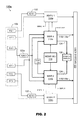
- FIG. 2 illustrates the navigation system of FIG. 1 incorporating MMR-based inertial integration
- FIG. 3A illustrates the addition of a dissimilar third inertial sensor to the navigation system of FIG. 2 ;
- FIG. 3B illustrates an implementation of the navigation system of FIG. 3A wherein a GNSS-assisted AHRS does not generate integrated position solutions;
- FIG. 4A illustrates a dual-channel implementation of the navigation system of FIG. 2 ;
- FIG. 4B illustrates the addition of a dissimilar third GNSS-assisted AHRS to the navigation system of FIG. 4A .
- inventive concepts are not limited in their application to the details of construction and the arrangement of the components or steps or methodologies set forth in the following description or illustrated in the drawings.
- inventive concepts disclosed herein may be practiced without these specific details.
- well-known features may not be described in detail to avoid unnecessarily complicating the instant disclosure.
- inventive concepts disclosed herein are capable of other embodiments or of being practiced or carried out in various ways. Also, it is to be understood that the phraseology and terminology employed herein is for the purpose of description and should not be regarded as limiting.
- a letter following a reference numeral is intended to reference an embodiment of the feature or element that may be similar, but not necessarily identical, to a previously described element or feature bearing the same reference numeral (e.g., 1, 1a, 1b).
- reference numeral e.g. 1, 1a, 1b
- Such shorthand notations are used for purposes of convenience only, and should not be construed to limit the inventive concepts disclosed herein in any way unless expressly stated to the contrary.
- any reference to “one embodiment,” or “some embodiments” means that a particular element, feature, structure, or characteristic described in connection with the embodiment is included in at least one embodiment of the inventive concepts disclosed herein.
- the appearances of the phrase “in some embodiments” in various places in the specification are not necessarily all referring to the same embodiment, and embodiments of the inventive concepts disclosed may include one or more of the features expressly described or inherently present herein, or any combination of sub-combination of two or more such features, along with any other features which may not necessarily be expressly described or inherently present in the instant disclosure.
- embodiments of the inventive concepts disclosed herein are directed to navigation systems incorporating inertial integration by GNSS-based multi-mode receivers (MMR).
- MMR multi-mode receivers
- a conventional system configuration incorporating three navigation-grade inertial reference units (IRU), may be modified by replacing one or more IRUs with cost-effective MMRs or high-performance microelectromechanical (MEMS) inertial sensors.
- the MMRs may isolate inertial sensors from satellite constellation changes by emulating IRUs, providing multiple channels of position solutions to user systems by integrating georeferenced data from their own GNSS receivers with inertial position data.
- an exemplary embodiment of a navigation system 100 may be embodied aboard an aircraft 102 and include a combination of inertial reference units 104 (IRU), global navigation satellite system (GNSS) enabled receivers 106 , and air data sensors 108 .
- IRU inertial reference units 104
- GNSS global navigation satellite system
- the GNSS-enabled receivers 106 may determine a georeferenced position of the aircraft 102 based on positioning signals received from navigational satellites 110 , 112 .
- the GNSS-enabled receivers 106 may be dual-antenna receivers incorporated into multi-mode receivers (MMR) including onboard processors for determining high integrity georeferenced position solutions.
- MMR multi-mode receivers
- the navigational satellites 110 , 112 may include components of diverse constellations, e.g., GPS, GLONASS, Compass, Beidou, Galileo, transmitting in diverse signal formats.
- the IRU 104 may incorporate navigation-grade inertial measurement units (IMU) and inertial sensors (e.g., accelerometers, gyrometers, compasses, magnetometers) and processors for determining inertial position data (e.g., platform-referenced position, velocity, acceleration, attitude, and rotational orientation data) of the aircraft 102 .
- IMU navigation-grade inertial measurement units
- inertial sensors e.g., accelerometers, gyrometers, compasses, magnetometers
- processors for determining inertial position data (e.g., platform-referenced position, velocity, acceleration, attitude, and rotational orientation data) of the aircraft 102 .
- This “pure” inertial position data may be combined with georeferenced position data from the
- Hybrid position solutions may include “coasted” solutions based primarily on inertial position data, in areas where GNSS signal reception may be unreliable or unavailable.
- air-data sensors 108 may include onboard sensor systems, e.g., pitot-static systems, angle of attack (AoA) sensors, and wing-mounted total air temperature (TAT) sensors, providing additional real-time air data (including, but not limited to, a barometric altitude, an airspeed, an angle of attack (AoA), a total air temperature (TAT), a vertical speed, and an overspeed) to the IRUs 104 via air data modules (ADM).
- ADM air data modules
- Implementations of the system 100 may replace one or more navigation-grade IRUs 104 (a conventional configuration may incorporate three IRUs: a main IRU dedicated to the pilot and co-pilot and a backup IRU should either main IRU fail) with a lower-cost IMU such as an attitude and heading reference system (AHRS), an air data AHRS (ADAHRS), or a microelectromechanical (MEMS) AHRS/ADAHRS.
- a navigation-grade IRUs 104 a conventional configuration may incorporate three IRUs: a main IRU dedicated to the pilot and co-pilot and a backup IRU should either main IRU fail
- a lower-cost IMU such as an attitude and heading reference system (AHRS), an air data AHRS (ADAHRS), or a microelectromechanical (MEMS) AHRS/ADAHRS.
- AHRS attitude and heading reference system
- ADAHRS air data AHRS
- MEMS microelectromechanical
- the navigation system 100 a may be implemented and may function similarly to the navigation system 100 of FIG. 1 , except that the navigation system 100 a may include dual power supply MMRs 114 a - b , ADIRUs 104 a - b , and a MEMS inertial measurement unit (IMU) 116 .
- the MMRs 114 a - b may integrate georeferenced position data (based on the received satellite-based navigation signals) with inertial position data from the ADIRUs 104 a - b to generate high-integrity position solutions ( 118 ), forwarding the solutions to user systems 120 of the aircraft ( 102 , FIG.
- the MMRs 114 a - b may include (but are not limited to) display systems, flight management systems (FMS), flight control systems, and fly-by-wire (FBW) systems.
- FMS flight management systems
- FBW fly-by-wire
- Each ADIRU 104 a - b may generate pure inertial position data (including, but not limited to, a rotational attitude, a heading, an acceleration, a ground speed, or a relative position of the aircraft 102 ) based on navigation-grade inertial sensors. Each ADIRU 104 a - b may further incorporate into its inertial position data air data from an ADM 122 . In some embodiments (e.g., if the navigation system 100 a is embodied in a ground-based vehicle), the ADIRUs 104 a - b may be standard inertial reference units (IRU) without access to air data.
- IRU inertial reference units
- Each MMR 114 a - b may generate secondary or “coasted” high-integrity position solutions ( 118 a ) by integrating the georeferenced position data with secondary inertial position data generated by the MEMS IMU 116 and output this secondary “coasted” integrated position solution 118 a as an additional primary channel to the user systems 120 .
- the MEMS IMU 116 may include secondary inertial sensors (e.g., an accelerometer, gyrometer, compass, or magnetometer 116 a ); the MEMS IMU 116 may receive air data from a dissimilar ADM ( 122 a ) connected to the air data sensors 108 .
- Each MMR 114 a - b may further generate a secondary (standby) GNSS-independent pure inertial position solution ( 124 ) by integrating secondary air data from the dissimilar ADM 122 a and secondary inertial data from the MEMS IMU 116 , the magnetometer 116 a , and other secondary inertial sensors.
- the secondary pure inertial position solutions 124 may be forwarded to a standby display 126 ; e.g., for use as a standby or backup solution.
- the navigation system 100 b may be implemented and may function similarly to the navigation system 100 a of FIG. 2 , except that the navigation system 100 b may replace the dual ADIRUs ( 104 a - b , FIG. 2 ) with navigation-grade inertial measurement units (IMU) 128 a - b (which lack the integrated processors of the ADIRUs 104 a - b ) and the MEMS IMU ( 116 , FIG. 1 ) with a MEMS air-data attitude and heading reference system (ADAHRS) 116 b .
- IMU inertial measurement units
- Each MMR 114 a - b may receive inertial position data from the navigation-grade IMUs 124 a - b , integrating the inertial position data with its own georeferenced position data (generated by dual-antenna GNSS receivers ( 106 , FIG. 1 ) as described above) to generate primary integrated position solutions ( 118 ). Because inertial integration is performed within the MMRs 114 a - b , the navigation-grade IMUs 128 a - b may be isolated from GNSS frequency and constellation changes.
- the MEMS ADAHRS 116 b may receive georeferenced position data from both MMRs 114 a - b , emulating an ADIRU ( 104 a - b , FIG. 2 ) by generating secondary integrated position solutions ( 118 a ) based on the georeferenced position data in addition to secondary inertial position data collected from, e.g., the magnetometer 116 a or other secondary inertial sensors of the MEMS ADAHRS, providing a low-cost alternative to the navigation-grade IMUs 128 a - b .
- Both MMRs 114 a - b as well as the MEMS ADAHRS 116 b may incorporate air data generated by ADMs 122 based on air data sensors 108 ; the MEMS ADAHRS 116 b may receive air data generated by a dissimilar ADM ( 122 a ).
- the MEMS ADAHRS 116 b may generate secondary pure inertial position solutions ( 124 ) by integrating secondary air data (from the dissimilar ADM 122 a ) and secondary inertial data from the MEMS ADAHRS 116 b itself (as well as the magnetometer 116 a and other secondary inertial sensors) and forward the secondary pure inertial position solutions 124 to the standby display 126 , e.g., for use as a standby or backup source of position solutions in the event of a fault in one or both navigation-grade IMUs 128 a - b .
- the MEMS ADAHRS 116 b may output the secondary integrated position solutions ( 118 a ) as an additional primary channel to the user systems 120 , due to the inherent dissimilarity of the secondary integrated position solutions 118 a of the MEMS ADAHRS to the primary high-integrity position solutions ( 118 ) generated by the MMRs 114 a - b.
- the navigation system 100 c may be implemented and may function similarly to the navigation system 100 b of FIG. 3A , except that the navigation system 100 c includes a MEMS ADAHRS 116 c without the capacity for GNSS integration (as compared to the MEMS ADAHRS 116 b of FIG. 2A ).
- the MEMS ADAHRS 116 c may output secondary inertial position data (collected by, e.g., the magnetometer 116 a and other secondary inertial sensors of the MEMS ADAHRS) to each MMR 114 a - b .
- Each MMR 114 a - b may generate a dual-channel output to the user systems 120 .
- each MMR 114 a - b may generate primary channel output (including primary integrated position solutions 118 ) based on the georeferenced position data generated by each MMR 114 a - b and the primary inertial position data received from both navigation-grade IMUs 128 a - b .
- each MMR 114 a - b may generate secondary channel output including secondary integrated position solutions ( 118 a ) based on the georeferenced position data and the secondary inertial position data generated by the MEMS ADAHRS 116 c .
- the MEMS ADAHRS 116 c may generate a secondary pure inertial position solution ( 124 ) based on secondary inertial position data and secondary air data from the dissimilar ADM 122 a , forwarding the secondary pure inertial position solution 124 to the standby display 126 .
- the navigation system 100 d may be implemented and may function similarly to the navigation system 100 a of FIG. 2 , except that the ADIRUs ( 104 a - b , FIG. 2 ) may be replaced by dual power supply MMRs 114 a - b and navigation-grade IMUs 128 a - b .
- Each MMR 114 a - b may generate a dual-channel output to the user systems 120 .
- each MMR 114 a - b may output a primary channel emulating an ADIRU ( 104 a - b , FIG.
- Each MMR 114 a - b may receive secondary inertial position data from the MEMS IMU 116 (or, alternatively, from an AHRS/ADAHRS ( 116 b - c , FIGS.
- each MMR 114 a - b may generate a secondary pure inertial solution ( 124 ) based on the secondary inertial position data from the MEMS IMU 116 (and secondary air data from the dissimilar ADM 122 a ), forwarding the secondary pure inertial solutions 124 to the standby display 126 .
- the user systems 120 may optionally receive pure inertial data (e.g., IMU rotation rates or accelerations) directly from the navigation-grade IMUs 128 a - b via the MMRs 114 a - b.
- the navigation system 100 e may be implemented and may function similarly to the navigation system 100 d of FIG. 4A , except that the navigation system 100 e may output a third channel to the user systems 120 by including a MEMS ADAHRS 116 d incorporating a dissimilar GNSS receiver (e.g., dissimilar to the dual-antenna GNSS receivers ( 106 , FIG. 1 ) of the MMRs 114 a - b ).
- a dissimilar GNSS receiver e.g., dissimilar to the dual-antenna GNSS receivers ( 106 , FIG. 1 ) of the MMRs 114 a - b .
- the MEMS ADAHRS 116 d may generate a secondary integrated position solution ( 118 a ) based on secondary inertial position data from the MEMS IMU 116 and magnetometer 116 a (and secondary air data generated by the dissimilar ADM 122 a ), providing the secondary integrated position solution 118 a to the user systems 120 as well as providing the secondary pure inertial solution ( 124 ) to the standby display 126 .
- systems and methods according to embodiments of the inventive concepts disclosed herein may provide for more cost-effective next-generation navigation systems with improved solution availability by replacing expensive navigation-grade IRUs and ADIRUs with lower-grade but high-performance MEMS inertial sensors and AHRS/ADAHRS.
- inertial sensors may be isolated from changes to GNSS frequencies and constellations, as inertial integration of position solutions is carried out by MMRs instead of by the IRUs.
- embodiments of the methods according to the inventive concepts disclosed herein may include one or more of the steps described herein. Further, such steps may be carried out in any desired order and two or more of the steps may be carried out simultaneously with one another. Two or more of the steps disclosed herein may be combined in a single step, and in some embodiments, one or more of the steps may be carried out as two or more sub-steps. Further, other steps or sub-steps may be carried in addition to, or as substitutes to one or more of the steps disclosed herein.
- inventive concepts disclosed herein are well adapted to carry out the objects and to attain the advantages mentioned herein as well as those inherent in the inventive concepts disclosed herein. While presently preferred embodiments of the inventive concepts disclosed herein have been described for purposes of this disclosure, it will be understood that numerous changes may be made which will readily suggest themselves to those skilled in the art and which are accomplished within the broad scope and coverage of the inventive concepts disclosed and claimed herein.
Abstract
Systems for multi-mode receiver (MMR)-based inertial integration of position solutions replace expensive IRUs with lower-grade but high-performance inertial sensors and GNSS-assisted MMRs, collecting inertial position data indicative of an aircraft position and integrating the inertial data with georeferenced position data within the MMRs. The inertial sensors may include microelectromechanical attitude and heading reference systems capable of generating coasted position solutions based on secondary inertial data and integrated with georeferenced data when it is available. The coasted position solutions may be used as a standby alternative to primary integrated solutions, or serve as an additional primary position solution.
Description
This application relates to the following applications concurrently filed herewith and each incorporated herein by these references in their entirety: AIR DATA, ATTITUDE, AND HEADING REFERENCE SYSTEM (ADAHRS) REPLACEMENT ARCHITECTURE by Jeffrey B. McNamara, James H. Doty, Vladislav Gavrilets, and Jesse W. Oltrogge, U.S. patent application Ser. No. 15/473,366.
A common approach to providing high-integrity coasting of position and velocity data after loss of a global navigation satellite system (GNSS) position signal in space is to employ a triple inertial reference unit (IRU; also inertial measurement unit (IMU) installation whereby each of three IRUs individually produces an accurate hybrid GNSS inertial position solution. However, each IRU may have a latent sensor error, the result of which may be rapid growth in position error after loss of GNSS data. A triple-IRU installation may detect these latent errors, or faults, by voting out the “bad” IRU (e.g., an outlier whose output disagrees with the other two).
However, cost pressures on original equipment manufacturers (OEMs) are driving the reduction or elimination of expensive or redundant navigation components such as IRUs. One approach is to replace one or two IRUs of the conventional triple-IRU installation with a lower-cost option such as a GNSS-aided attitude and heading reference system (AHRS). In addition, changes in GNSS signaling and the regulatory environment will drive newer, more flexible architectures that can accommodate multiple frequencies and multiple satellite constellations. IRU and AHRS components may require frequent modification or replacement in order to adapt to these changes.
In one aspect, embodiments of the inventive concepts disclosed herein are directed to a multi-mode receiver (MMR)-based navigation system. The system may include at least one inertial reference unit (IRU) for generating “pure” inertial position data via inertial position sensors. The IRU may include processors for outputting the inertial position data to MMRs of the system as well as aircraft display and flight control systems. The system may include MMRs incorporating global navigation satellite system (GNSS) receivers for receiving position signals from external satellites. The MMRs may include processors for generating georeferenced position data based on the received position signals. The MMR processors may receive the inertial position data from each IRU and generate integrated position solutions (e.g., position/velocity/time (PVT) solutions) based on the georeferenced data and the inertial data as well as a pure inertial solution based on secondary inertial sensors and/or air data. The MMR processors may output the integrated solutions to the user systems and the pure inertial solution to a standby display.
In a further aspect, embodiments of the inventive concepts disclosed herein are directed to an MMR-based navigation system. The system may include navigation-grade inertial sensors for generating inertial position data indicative of an aircraft position. The system may include MMRs incorporating GNSS-based receivers for receiving satellite-based position signals. The MMRs may include processors for generating georeferenced position data based on the received position signals. The MMR processors may receive the inertial position data from the navigation-grade inertial sensors, generating primary integrated position solutions based on the georeferenced data and the inertial position data, and outputting the integrated position solutions to user display and flight control systems of the aircraft. The AHRS may generate secondary inertial position data via secondary inertial sensors and receive secondary air data from a secondary air data module. The AHRS may include processors for receiving the georeferenced data from the MMRs and generating secondary integrated position solutions based on the georeferenced data and the inertial position data from the secondary inertial sensors, outputting the secondary integrated position solutions to the user systems. The AHRS may additionally generate pure inertial position solutions based on the secondary inertial position data and secondary air data, outputting the pure secondary inertial position solutions to a standby display.
In a still further aspect, embodiments of the inventive concepts disclosed herein are directed to a dual-MMR navigation system. The system may include primary or navigation-grade inertial sensors for generating primary inertial position data indicative of an aircraft position and secondary or microelectromechanical (MEMS) inertial sensors for generating secondary inertial position data indicative of the aircraft position. The system may include two or more MMRs, each MMR incorporating a GNSS receiver for receiving navigation signals from external satellites. Each MMR may include processors for generating georeferenced position data based on the received navigation signals. The MMR processors may receive the inertial position data from the primary and secondary inertial sensors and generate primary integrated position solutions, based on the georeferenced data and the primary inertial data, and secondary integrated position solutions, based on the georeferenced data and the secondary inertial data. The MMR processors may additionally generate pure inertial position solutions based on the secondary inertial data. The MMR processors may output the integrated position solutions to user display and flight control systems of the aircraft, and output the pure inertial solutions to a standby display.
Implementations of the inventive concepts disclosed herein may be better understood when consideration is given to the following detailed description thereof. Such description makes reference to the included drawings, which are not necessarily to scale, and in which some features may be exaggerated and some features may be omitted or may be represented schematically in the interest of clarity. Like reference numerals in the drawings may represent and refer to the same or similar element, feature, or function. In the drawings:
Before explaining at least one embodiment of the inventive concepts disclosed herein in detail, it is to be understood that the inventive concepts are not limited in their application to the details of construction and the arrangement of the components or steps or methodologies set forth in the following description or illustrated in the drawings. In the following detailed description of embodiments of the instant inventive concepts, numerous specific details are set forth in order to provide a more thorough understanding of the inventive concepts. However, it will be apparent to one of ordinary skill in the art having the benefit of the instant disclosure that the inventive concepts disclosed herein may be practiced without these specific details. In other instances, well-known features may not be described in detail to avoid unnecessarily complicating the instant disclosure. The inventive concepts disclosed herein are capable of other embodiments or of being practiced or carried out in various ways. Also, it is to be understood that the phraseology and terminology employed herein is for the purpose of description and should not be regarded as limiting.
As used herein a letter following a reference numeral is intended to reference an embodiment of the feature or element that may be similar, but not necessarily identical, to a previously described element or feature bearing the same reference numeral (e.g., 1, 1a, 1b). Such shorthand notations are used for purposes of convenience only, and should not be construed to limit the inventive concepts disclosed herein in any way unless expressly stated to the contrary.
Further, unless expressly stated to the contrary, “or” refers to an inclusive or and not to an exclusive or. For example, a condition A or B is satisfied by anyone of the following: A is true (or present) and B is false (or not present), A is false (or not present) and B is true (or present), and both A and B are true (or present).
In addition, use of the “a” or “an” are employed to describe elements and components of embodiments of the instant inventive concepts. This is done merely for convenience and to give a general sense of the inventive concepts, and “a” and “an” are intended to include one or at least one and the singular also includes the plural unless it is obvious that it is meant otherwise.
Finally, as used herein any reference to “one embodiment,” or “some embodiments” means that a particular element, feature, structure, or characteristic described in connection with the embodiment is included in at least one embodiment of the inventive concepts disclosed herein. The appearances of the phrase “in some embodiments” in various places in the specification are not necessarily all referring to the same embodiment, and embodiments of the inventive concepts disclosed may include one or more of the features expressly described or inherently present herein, or any combination of sub-combination of two or more such features, along with any other features which may not necessarily be expressly described or inherently present in the instant disclosure.
Broadly, embodiments of the inventive concepts disclosed herein are directed to navigation systems incorporating inertial integration by GNSS-based multi-mode receivers (MMR). A conventional system configuration, incorporating three navigation-grade inertial reference units (IRU), may be modified by replacing one or more IRUs with cost-effective MMRs or high-performance microelectromechanical (MEMS) inertial sensors. The MMRs may isolate inertial sensors from satellite constellation changes by emulating IRUs, providing multiple channels of position solutions to user systems by integrating georeferenced data from their own GNSS receivers with inertial position data.
Referring now to FIG. 1 , an exemplary embodiment of a navigation system 100 according to embodiments of the inventive concepts herein may be embodied aboard an aircraft 102 and include a combination of inertial reference units 104 (IRU), global navigation satellite system (GNSS) enabled receivers 106, and air data sensors 108. For example, the GNSS-enabled receivers 106 may determine a georeferenced position of the aircraft 102 based on positioning signals received from navigational satellites 110, 112. The GNSS-enabled receivers 106 may be dual-antenna receivers incorporated into multi-mode receivers (MMR) including onboard processors for determining high integrity georeferenced position solutions. The navigational satellites 110, 112 may include components of diverse constellations, e.g., GPS, GLONASS, Compass, Beidou, Galileo, transmitting in diverse signal formats. The IRU 104 may incorporate navigation-grade inertial measurement units (IMU) and inertial sensors (e.g., accelerometers, gyrometers, compasses, magnetometers) and processors for determining inertial position data (e.g., platform-referenced position, velocity, acceleration, attitude, and rotational orientation data) of the aircraft 102. This “pure” inertial position data may be combined with georeferenced position data from the GNSS-enabled receivers 106 to generate high-integrity hybrid position solutions. Hybrid position solutions may include “coasted” solutions based primarily on inertial position data, in areas where GNSS signal reception may be unreliable or unavailable. If, for example, the IRU 104 is an air-data IRU (ADIRU), air-data sensors 108 may include onboard sensor systems, e.g., pitot-static systems, angle of attack (AoA) sensors, and wing-mounted total air temperature (TAT) sensors, providing additional real-time air data (including, but not limited to, a barometric altitude, an airspeed, an angle of attack (AoA), a total air temperature (TAT), a vertical speed, and an overspeed) to the IRUs 104 via air data modules (ADM). Implementations of the system 100 may replace one or more navigation-grade IRUs 104 (a conventional configuration may incorporate three IRUs: a main IRU dedicated to the pilot and co-pilot and a backup IRU should either main IRU fail) with a lower-cost IMU such as an attitude and heading reference system (AHRS), an air data AHRS (ADAHRS), or a microelectromechanical (MEMS) AHRS/ADAHRS.
Referring now to FIG. 2 , the navigation system 100 a may be implemented and may function similarly to the navigation system 100 of FIG. 1 , except that the navigation system 100 a may include dual power supply MMRs 114 a-b, ADIRUs 104 a-b, and a MEMS inertial measurement unit (IMU) 116. The MMRs 114 a-b may integrate georeferenced position data (based on the received satellite-based navigation signals) with inertial position data from the ADIRUs 104 a-b to generate high-integrity position solutions (118), forwarding the solutions to user systems 120 of the aircraft (102, FIG. 1 ), which may include (but are not limited to) display systems, flight management systems (FMS), flight control systems, and fly-by-wire (FBW) systems. Because inertial integration of georeferenced position data is performed by the MMRs 114 a-b rather than the ADIRUs 104 a-b, the ADIRUs (as well as the MEMS IMU 116) may be isolated from changes to GNSS constellations or frequencies; only the MMRs 114 a-b may require updating.
Each ADIRU 104 a-b may generate pure inertial position data (including, but not limited to, a rotational attitude, a heading, an acceleration, a ground speed, or a relative position of the aircraft 102) based on navigation-grade inertial sensors. Each ADIRU 104 a-b may further incorporate into its inertial position data air data from an ADM 122. In some embodiments (e.g., if the navigation system 100 a is embodied in a ground-based vehicle), the ADIRUs 104 a-b may be standard inertial reference units (IRU) without access to air data.
Each MMR 114 a-b may generate secondary or “coasted” high-integrity position solutions (118 a) by integrating the georeferenced position data with secondary inertial position data generated by the MEMS IMU 116 and output this secondary “coasted” integrated position solution 118 a as an additional primary channel to the user systems 120. The MEMS IMU 116 may include secondary inertial sensors (e.g., an accelerometer, gyrometer, compass, or magnetometer 116 a); the MEMS IMU 116 may receive air data from a dissimilar ADM (122 a) connected to the air data sensors 108. Each MMR 114 a-b may further generate a secondary (standby) GNSS-independent pure inertial position solution (124) by integrating secondary air data from the dissimilar ADM 122 a and secondary inertial data from the MEMS IMU 116, the magnetometer 116 a, and other secondary inertial sensors. The secondary pure inertial position solutions 124 may be forwarded to a standby display 126; e.g., for use as a standby or backup solution.
Referring now to FIG. 3A , the navigation system 100 b may be implemented and may function similarly to the navigation system 100 a of FIG. 2 , except that the navigation system 100 b may replace the dual ADIRUs (104 a-b, FIG. 2 ) with navigation-grade inertial measurement units (IMU) 128 a-b (which lack the integrated processors of the ADIRUs 104 a-b) and the MEMS IMU (116, FIG. 1 ) with a MEMS air-data attitude and heading reference system (ADAHRS) 116 b. Each MMR 114 a-b may receive inertial position data from the navigation-grade IMUs 124 a-b, integrating the inertial position data with its own georeferenced position data (generated by dual-antenna GNSS receivers (106, FIG. 1 ) as described above) to generate primary integrated position solutions (118). Because inertial integration is performed within the MMRs 114 a-b, the navigation-grade IMUs 128 a-b may be isolated from GNSS frequency and constellation changes. The MEMS ADAHRS 116 b may receive georeferenced position data from both MMRs 114 a-b, emulating an ADIRU (104 a-b, FIG. 2 ) by generating secondary integrated position solutions (118 a) based on the georeferenced position data in addition to secondary inertial position data collected from, e.g., the magnetometer 116 a or other secondary inertial sensors of the MEMS ADAHRS, providing a low-cost alternative to the navigation-grade IMUs 128 a-b. Both MMRs 114 a-b as well as the MEMS ADAHRS 116 b may incorporate air data generated by ADMs 122 based on air data sensors 108; the MEMS ADAHRS 116 b may receive air data generated by a dissimilar ADM (122 a). The MEMS ADAHRS 116 b may generate secondary pure inertial position solutions (124) by integrating secondary air data (from the dissimilar ADM 122 a) and secondary inertial data from the MEMS ADAHRS 116 b itself (as well as the magnetometer 116 a and other secondary inertial sensors) and forward the secondary pure inertial position solutions 124 to the standby display 126, e.g., for use as a standby or backup source of position solutions in the event of a fault in one or both navigation-grade IMUs 128 a-b. However, the MEMS ADAHRS 116 b may output the secondary integrated position solutions (118 a) as an additional primary channel to the user systems 120, due to the inherent dissimilarity of the secondary integrated position solutions 118 a of the MEMS ADAHRS to the primary high-integrity position solutions (118) generated by the MMRs 114 a-b.
Referring now to FIG. 3B , the navigation system 100 c may be implemented and may function similarly to the navigation system 100 b of FIG. 3A , except that the navigation system 100 c includes a MEMS ADAHRS 116 c without the capacity for GNSS integration (as compared to the MEMS ADAHRS 116 b of FIG. 2A ). The MEMS ADAHRS 116 c may output secondary inertial position data (collected by, e.g., the magnetometer 116 a and other secondary inertial sensors of the MEMS ADAHRS) to each MMR 114 a-b. Each MMR 114 a-b may generate a dual-channel output to the user systems 120. For example, each MMR 114 a-b may generate primary channel output (including primary integrated position solutions 118) based on the georeferenced position data generated by each MMR 114 a-b and the primary inertial position data received from both navigation-grade IMUs 128 a-b. Similarly, each MMR 114 a-b may generate secondary channel output including secondary integrated position solutions (118 a) based on the georeferenced position data and the secondary inertial position data generated by the MEMS ADAHRS 116 c. The MEMS ADAHRS 116 c may generate a secondary pure inertial position solution (124) based on secondary inertial position data and secondary air data from the dissimilar ADM 122 a, forwarding the secondary pure inertial position solution 124 to the standby display 126.
Referring now to FIG. 4A , the navigation system 100 d may be implemented and may function similarly to the navigation system 100 a of FIG. 2 , except that the ADIRUs (104 a-b, FIG. 2 ) may be replaced by dual power supply MMRs 114 a-b and navigation-grade IMUs 128 a-b. Each MMR 114 a-b may generate a dual-channel output to the user systems 120. For example, each MMR 114 a-b may output a primary channel emulating an ADIRU (104 a-b, FIG. 2 ) by integrating primary position solutions (118) based on georeferenced position data (based on position signals received by a dual-antenna GNSS receiver (106, FIG. 1 )) and inertial position data generated by each navigation-grade IMU 128 a-b. Each MMR 114 a-b may receive secondary inertial position data from the MEMS IMU 116 (or, alternatively, from an AHRS/ADAHRS (116 b-c, FIGS. 3A /3B)), generating a secondary integrated position solution (118 a) based on secondary air data (from dissimilar ADM 122 a) and secondary inertial position data from, e.g., the magnetometer 116 a and the MEMS IMU 116, forwarding the secondary integrated solution to the user systems 120. Finally, each MMR 114 a-b may generate a secondary pure inertial solution (124) based on the secondary inertial position data from the MEMS IMU 116 (and secondary air data from the dissimilar ADM 122 a), forwarding the secondary pure inertial solutions 124 to the standby display 126. The user systems 120 may optionally receive pure inertial data (e.g., IMU rotation rates or accelerations) directly from the navigation-grade IMUs 128 a-b via the MMRs 114 a-b.
Referring now to FIG. 4B , the navigation system 100 e may be implemented and may function similarly to the navigation system 100 d of FIG. 4A , except that the navigation system 100 e may output a third channel to the user systems 120 by including a MEMS ADAHRS 116 d incorporating a dissimilar GNSS receiver (e.g., dissimilar to the dual-antenna GNSS receivers (106, FIG. 1 ) of the MMRs 114 a-b). The MEMS ADAHRS 116 d may generate a secondary integrated position solution (118 a) based on secondary inertial position data from the MEMS IMU 116 and magnetometer 116 a (and secondary air data generated by the dissimilar ADM 122 a), providing the secondary integrated position solution 118 a to the user systems 120 as well as providing the secondary pure inertial solution (124) to the standby display 126.
As will be appreciated from the above, systems and methods according to embodiments of the inventive concepts disclosed herein may provide for more cost-effective next-generation navigation systems with improved solution availability by replacing expensive navigation-grade IRUs and ADIRUs with lower-grade but high-performance MEMS inertial sensors and AHRS/ADAHRS. In addition, inertial sensors may be isolated from changes to GNSS frequencies and constellations, as inertial integration of position solutions is carried out by MMRs instead of by the IRUs.
It is to be understood that embodiments of the methods according to the inventive concepts disclosed herein may include one or more of the steps described herein. Further, such steps may be carried out in any desired order and two or more of the steps may be carried out simultaneously with one another. Two or more of the steps disclosed herein may be combined in a single step, and in some embodiments, one or more of the steps may be carried out as two or more sub-steps. Further, other steps or sub-steps may be carried in addition to, or as substitutes to one or more of the steps disclosed herein.
From the above description, it is clear that the inventive concepts disclosed herein are well adapted to carry out the objects and to attain the advantages mentioned herein as well as those inherent in the inventive concepts disclosed herein. While presently preferred embodiments of the inventive concepts disclosed herein have been described for purposes of this disclosure, it will be understood that numerous changes may be made which will readily suggest themselves to those skilled in the art and which are accomplished within the broad scope and coverage of the inventive concepts disclosed and claimed herein.
Claims (15)
1. A multi-mode receiver (MMR)-based navigation system, comprising:
at least one inertial reference unit (IRU) comprising:
at least one first inertial measurement unit (IMU) configured to generate first platform-referenced position data associated with an aircraft; and
at least one first processor coupled to the at least one first IMU and configured to output the first platform-referenced position data to at least one of a multi-mode receiver (MMR) associated with the aircraft and a user system of the aircraft;
at least one second IMU configured to generate second platform-referenced position data associated with the aircraft;
the at least one multi-mode receiver (MMR) coupled to the at least one IRU and the at least one second IMU and comprising:
at least one global navigation satellite system (GNSS) receiver configured to receive one or more satellite-based navigation signals from a source external to the aircraft; and
at least one second processor coupled to the GNSS receiver and configured to:
receive the at least one first platform-referenced position data from the at least one first IRU;
receive the second platform-referenced position data from the at least one second IMU;
generate georeferenced position data associated with the aircraft based on the one or more satellite-based navigation signals;
generate at least one first integrated position solution based on one or more of the georeferenced position data and the first platform-referenced position data;
generate at least one second integrated position solution based on one or more of the georeferenced position data and the second platform-referenced position data;
generate at least one pure inertial position solution based on the second platform-referenced position data;
output the at least one pure inertial position solution to a standby display; and
output one or more of the at least one first integrated position solution and the at least one second integrated position solution to the at least one user system.
2. The MMR-based navigation system of claim 1 , wherein:
the at least one IRU includes at least one air-data IRU (ADIRU) coupled to at least one first air data module (ADM), the first ADM coupled to one or more air data sensors, the at least one first processor configured to:
receive first air data from the at least one first ADM; and
output the first air data to the at least one MMR;
and
the at least one MMR is coupled to at least one second ADM, the second ADM coupled to the one or more air data sensors, and the at least one second processor is configured to:
receive second air data from the at least one second ADM;
generate the at least one first integrated position solution based on one or more of the georeferenced position data, the first platform-referenced position data, and the first air data;
generate the at least one second integrated position solution based on one or more of the georeferenced position data, the second platform-referenced position data, and the second air data; and
generate the at least one pure inertial position solution based on one or more of the second platform-referenced position data and the second air data.
3. The MMR-based navigation system of claim 2 , wherein the one or more air data sensors include one or more of a pitot tube, a static port, an angle of attack (AoA) sensor, and a total air temperature (TAT) sensor.
4. The MMR-based navigation system of claim 1 , wherein the at least one second IMU includes at least one of a magnetometer, a compass, and a microelectromagnetic (MEMS) IMU.
5. A multi-mode receiver (MMR)-based navigation system, comprising:
at least one first inertial measurement unit (IMU) configured to generate first platform-referenced position data associated with an aircraft;
at least one MMR coupled to the at least one first IMU, the at least one MMR comprising:
at least one satellite-based receiver configured to receive one or more satellite-based navigational signals from at least one source external to the aircraft;
at least one first processor coupled to the at least one satellite-based receiver and configured to:
generate georeferenced position data associated with the aircraft based on the one or more satellite-based navigational signals;
receive the first platform-referenced position data from the at least one first IMU;
generate at least one first integrated position solution based on one or more of the georeferenced position data and the first platform-referenced position data; and
output the at least one first integrated position solution to the at least one user system;
and
at least one AHRS coupled to the at least one MMR and comprising:
at least one second IMU configured to generate the second platform-referenced position data; and
at least one second processor coupled to the at least one second IMU and configured to:
receive the georeferenced position data from the at least one MMR;
generate at least one second integrated position solution based on one or more of the georeferenced position data and the second platform-referenced position data;
generate at least one pure inertial position solution based on the second platform-referenced position data;
output the at least one second integrated position solution to the at least one user system; and
output the at least one pure inertial position solution to at least one standby display.
6. The MMR-based navigation system of claim 5 , wherein:
the at least one MMR is coupled to at least one first air data module (ADM), the first ADM coupled to one or more air data sensors, the at least one first processor configured to:
receive first air data from the at least one first ADM; and
generate the at least one first integrated position solution based on one or more of the georeferenced position data, the first platform-referenced position data, and the first air data;
and
the at least one AHRS is coupled to at least one second ADM, the second ADM coupled to the one or more air data sensors, the at least one second processor configured to:
receive second air data from the at least one second ADM;
generate the at least one second integrated position solution based on one or more of the georeferenced position data, the second platform-referenced position data, and the second air data; and
generate the at least one pure inertial position solution based on one or more of the second platform-referenced position data and the second air data.
7. The MMR-based navigation system of claim 6 , wherein the at least one first processor is configured to:
receive the second platform-referenced position data from the at least one AHRS;
generate the at least one second integrated position solution based on one or more of the georeferenced position data and the second platform-referenced position data; and
output the at least one second integrated position solution to the at least one user system.
8. The MMR-based navigation system of claim 6 , wherein the one or more air data sensors include one or more of a pitot tube, a static port, an angle of attack (AoA) sensor, and a total air temperature (TAT) sensor.
9. The MMR-based navigation system of claim 5 , wherein:
the at least one first IMU includes at least one navigation-grade IMU; and
the at least one second IMU includes at least one of a magnetometer, a compass, and a microelectromagnetic (MEMS) IMU.
10. A multi-mode receiver (MMR)-based navigation system, comprising:
at least one first navigation-grade inertial measurement unit (IMU) configured to generate first platform-referenced position data associated with an aircraft;
at least one second IMU configured to generate second platform-referenced position data associated with the aircraft, the second IMU including at least one of a magnetometer, a compass, and a microelectromagnetic (MEMS) IMU;
and
at least one MMR coupled to one or more of the at least one first IMU and the at least one second IMU, the at least one MMR comprising:
at least one global navigation satellite system (GNSS) receiver configured to receive one or more navigational signals from at least one source external to the aircraft; and
at least one first processor coupled to the at least one GNSS receiver and configured to:
generate georeferenced position data associated with the aircraft based on the one or more navigational signals;
receive one or more of the first platform-referenced position data and the second platform-referenced position data;
generate at least one first integrated position solution based on one or more of the georeferenced position data and the first platform-referenced position data;
generate at least one second integrated position solution based on one or more of the georeferenced position data and the second platform-referenced position data;
generate at least one pure inertial position solution based on the second platform-referenced position data;
output one or more of the at least one first integrated position solution and the at least one second integrated position solution to at least one user system associated with the aircraft; and
output the at least one pure inertial position solution to at least one standby display associated with the aircraft.
11. The MMR-based navigation solution of claim 10 , wherein:
the at least one MMR is coupled to at least one of a first air data module (ADM) and a second ADM, the first ADM and the second ADM coupled to one or more air data sensors, and the at least one first processor is further configured to:
receive first air data associated with the aircraft from the at least one first ADM;
receive second air data associated with the aircraft from the at least one second ADM;
generate the at least one first integrated position solution based on one or more of the georeferenced position data, the first platform-referenced position data, and the first air data,
generate the at least one second integrated position solution based on one or more of the georeferenced position data, the second platform-referenced position data, and the second air data; and
generate the at least one pure inertial position solution based on one or more of the second platform-referenced position data and the second air data.
12. The MMR-based navigation solution of claim 11 , wherein the at least one MMR is a first MMR coupled to the at least one first IMU and comprising at least one first GNSS receiver, further comprising:
at least one air data attitude and heading reference system (ADAHRS) coupled to the at least one second IMU and the at least one second air data sensor, the at least one ADAHRS comprising:
at least one second GNSS receiver configured to receive the one or more navigational signals; and
at least one third processor coupled to the second GNSS receiver and configured to:
generate second georeferenced position data based on the one or more navigational signals;
receive the second platform-referenced position data from the at least one second IMU;
receive the second air data from the at least one second ADM; and
generate the at least one second integrated position solution based on one or more of the second georeferenced position data, the second platform-referenced position data, and the second air data.
13. The MMR-based navigation solution of claim 10 , wherein the at least one first IMU is configured to output the first platform-referenced position data to the at least one user system.
14. The MMR-based navigation solution of claim 10 , wherein the at least one second IMU is configured to output the second platform-referenced position data to the at least one user system.
15. The MMR-based navigation solution of claim 10 , wherein the at least one user system includes one or more of a display system, a flight control system, a flight management system (FMS), and a fly-by-wire (FBW) system.
Priority Applications (1)
| Application Number | Priority Date | Filing Date | Title |
|---|---|---|---|
| US15/473,406 US10066944B1 (en) | 2017-03-29 | 2017-03-29 | Multi-mode receiver (MMR) based inertial integration |
Applications Claiming Priority (1)
| Application Number | Priority Date | Filing Date | Title |
|---|---|---|---|
| US15/473,406 US10066944B1 (en) | 2017-03-29 | 2017-03-29 | Multi-mode receiver (MMR) based inertial integration |
Publications (1)
| Publication Number | Publication Date |
|---|---|
| US10066944B1 true US10066944B1 (en) | 2018-09-04 |
Family
ID=63295194
Family Applications (1)
| Application Number | Title | Priority Date | Filing Date |
|---|---|---|---|
| US15/473,406 Active US10066944B1 (en) | 2017-03-29 | 2017-03-29 | Multi-mode receiver (MMR) based inertial integration |
Country Status (1)
| Country | Link |
|---|---|
| US (1) | US10066944B1 (en) |
Cited By (2)
| Publication number | Priority date | Publication date | Assignee | Title |
|---|---|---|---|---|
| US20170336517A1 (en) * | 2014-12-11 | 2017-11-23 | Airbus Helicopters | Redundant device of piloting sensors for a rotary-wing aircraft |
| WO2021217604A1 (en) * | 2020-04-30 | 2021-11-04 | Baidu.Com Times Technology (Beijing) Co., Ltd. | Dual inertial measurement units for inertial navigation system |
Citations (3)
| Publication number | Priority date | Publication date | Assignee | Title |
|---|---|---|---|---|
| US6965816B2 (en) * | 2001-10-01 | 2005-11-15 | Kline & Walker, Llc | PFN/TRAC system FAA upgrades for accountable remote and robotics control to stop the unauthorized use of aircraft and to improve equipment management and public safety in transportation |
| US7164383B2 (en) * | 2002-09-25 | 2007-01-16 | The Board Of Regents Of The University Of Oklahoma | Navigation system using locally augmented GPS |
| US8818582B2 (en) * | 2011-09-22 | 2014-08-26 | Airbus Operations S.A.S. | Method and system for determining the position of an aircraft during its approach to a landing runway |
-
2017
- 2017-03-29 US US15/473,406 patent/US10066944B1/en active Active
Patent Citations (3)
| Publication number | Priority date | Publication date | Assignee | Title |
|---|---|---|---|---|
| US6965816B2 (en) * | 2001-10-01 | 2005-11-15 | Kline & Walker, Llc | PFN/TRAC system FAA upgrades for accountable remote and robotics control to stop the unauthorized use of aircraft and to improve equipment management and public safety in transportation |
| US7164383B2 (en) * | 2002-09-25 | 2007-01-16 | The Board Of Regents Of The University Of Oklahoma | Navigation system using locally augmented GPS |
| US8818582B2 (en) * | 2011-09-22 | 2014-08-26 | Airbus Operations S.A.S. | Method and system for determining the position of an aircraft during its approach to a landing runway |
Non-Patent Citations (2)
| Title |
|---|
| Glen Gibbons, Challenges in GNSS/INS Integration, Inside GNSS, Jan./Feb. 2012, http://insidegnss.com/node/2950, 2 pages. |
| Philipp Clausen et al., Position Accuracy with Redundant MEMS IMU for Road Applications, European Navigation Conference GNSS, Apr. 7-10, 2015, Proceedings of the ENC-GNSS 2015, 8 pages. |
Cited By (5)
| Publication number | Priority date | Publication date | Assignee | Title |
|---|---|---|---|---|
| US20170336517A1 (en) * | 2014-12-11 | 2017-11-23 | Airbus Helicopters | Redundant device of piloting sensors for a rotary-wing aircraft |
| US10935672B2 (en) * | 2014-12-11 | 2021-03-02 | Airbus Helicopters | Redundant device of piloting sensors for a rotary-wing aircraft |
| WO2021217604A1 (en) * | 2020-04-30 | 2021-11-04 | Baidu.Com Times Technology (Beijing) Co., Ltd. | Dual inertial measurement units for inertial navigation system |
| CN113874680A (en) * | 2020-04-30 | 2021-12-31 | 百度时代网络技术(北京)有限公司 | Dual inertial measurement unit for inertial navigation system |
| US11592581B2 (en) | 2020-04-30 | 2023-02-28 | Baidu Usa Llc | Dual inertial measurement units for inertial navigation system |
Similar Documents
| Publication | Publication Date | Title |
|---|---|---|
| US10209076B1 (en) | Air data, attitude and heading reference system (ADAHRS) replacement architecture | |
| US6654685B2 (en) | Apparatus and method for navigation of an aircraft | |
| US5841537A (en) | Synthesized attitude and heading inertial reference | |
| JP4014642B2 (en) | GPS / IRS global positioning method and device with integrity loss countermeasures | |
| US6516272B2 (en) | Positioning and data integrating method and system thereof | |
| US20120004846A1 (en) | Air navigation device with inertial sensor units, radio navigation receivers, and air navigation technique using such elements | |
| AU2005250920B2 (en) | Systems and methods for estimating position, attitude, and/or heading of a vehicle | |
| Colomina et al. | Towards a new paradigm for high-resolution low-cost photogrammetryand remote sensing | |
| US7328104B2 (en) | Systems and methods for improved inertial navigation | |
| US6493631B1 (en) | Geophysical inertial navigation system | |
| US8082099B2 (en) | Aircraft navigation using the global positioning system and an attitude and heading reference system | |
| US20030135327A1 (en) | Low cost inertial navigator | |
| US20090228210A1 (en) | Navigation system based on neutrino detection | |
| US7592952B2 (en) | Method of locating a vehicle from satellite data | |
| US20110184592A1 (en) | Alternate airspeed computation when air data computer (adc) fails | |
| US8909471B1 (en) | Voting system and method using doppler aided navigation | |
| KR100990386B1 (en) | Flight control system and control method of unmanned Aerial Vehicle | |
| US6266582B1 (en) | GPS analytic redundancy for gyroscope failure detection | |
| US10302450B1 (en) | Methods and systems for high accuracy and integrity estimation of flight critical aircraft states | |
| EP3680617B1 (en) | Restoring navigational performance for a navigational system | |
| CA2811772A1 (en) | Device for determining location information and inertial primary references for an aircraft | |
| CA2767526A1 (en) | Method and system for determining navigation parameters of an aircraft | |
| GB2444814A (en) | Estimating inertial acceleration bias errors | |
| US10066944B1 (en) | Multi-mode receiver (MMR) based inertial integration | |
| US9031785B2 (en) | System and method for aircraft navigation assistance |
Legal Events
| Date | Code | Title | Description |
|---|---|---|---|
| STCF | Information on status: patent grant |
Free format text: PATENTED CASE |
|
| MAFP | Maintenance fee payment |
Free format text: PAYMENT OF MAINTENANCE FEE, 4TH YEAR, LARGE ENTITY (ORIGINAL EVENT CODE: M1551); ENTITY STATUS OF PATENT OWNER: LARGE ENTITY Year of fee payment: 4 |