US1006639A - Metal running-board frame for box-cars. - Google Patents
Metal running-board frame for box-cars. Download PDFInfo
- Publication number
- US1006639A US1006639A US60739311A US1911607393A US1006639A US 1006639 A US1006639 A US 1006639A US 60739311 A US60739311 A US 60739311A US 1911607393 A US1911607393 A US 1911607393A US 1006639 A US1006639 A US 1006639A
- Authority
- US
- United States
- Prior art keywords
- cars
- box
- board frame
- running
- metal running
- Prior art date
- Legal status (The legal status is an assumption and is not a legal conclusion. Google has not performed a legal analysis and makes no representation as to the accuracy of the status listed.)
- Expired - Lifetime
Links
- 239000002184 metal Substances 0.000 title description 4
- 229910052751 metal Inorganic materials 0.000 title description 4
- 238000010276 construction Methods 0.000 description 3
- 229910000746 Structural steel Inorganic materials 0.000 description 2
- 241000252203 Clupea harengus Species 0.000 description 1
- 235000019514 herring Nutrition 0.000 description 1
- 235000000396 iron Nutrition 0.000 description 1
Images
Classifications
-
- B—PERFORMING OPERATIONS; TRANSPORTING
- B61—RAILWAYS
- B61D—BODY DETAILS OR KINDS OF RAILWAY VEHICLES
- B61D17/00—Construction details of vehicle bodies
- B61D17/04—Construction details of vehicle bodies with bodies of metal; with composite, e.g. metal and wood body structures
- B61D17/12—Roofs
- B61D17/14—Roofs with gangways
Definitions
- This invention relates to a running board frame for box cars and the like.
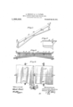
- FIG. l. is a perspective view of the invention.
- Fig. 2. 1s a side elevation of same.
- Fig. 8. is a plan view showing the runnin boards in position.
- Fig. 4. is an enlarge section on the line X X, Fig. 3.
- Fig. 5 is a fragmentary side view of a car roof showing the invention as applied.
- a supporting member or saddle of peculiar construction and design which saddle is adapted to be placed astride the roof of a car and securely bolted thereto.
- This saddle is formed as shown in Fig.v 1, preferably of cast or drop-forged metal, and consists of a ilat tread A, which is bent at an obtuse angle to conform to the roof slopes on opposite sides of the ridge of the car.
- a vertically arranged web 2 Formed on the upper face of the tread A .and extending longitudinally central thereof is a vertically arranged web 2, the upper edge of which terminates in a horizontally disposed flange '3 which projects laterally on each "side of the web 2.
- This flange 3 is bent upwardly and inwardly at each end to form hook members 4-4 which are adapted to engage the outer edges of the running boards 5 5 when the latter are a notch 6 some distance on each side of the center ofthe saddle, each of' which notches is designed to receive an, angle-iron 7, as shown in Fig. 2,V the angle-irons 7 being placed within the notches5 6 with their upper face flush with the top of the flange 3,
- a number of the saddles formed as just described, are placed astride the ridge of the placed upon the saddle as shown invFig. 2.
- the flange 3 and web 2- are cut away to formroof of a carat suitable distances apart, and
- the angles 7 are rigidly 'secured to the car roof by means of bolts9 which pass through the ends of the tread A and the roof rafters, .as shown in Fig. 2.
- the angles 7 are then placed in position on the saddles andl secured thereto, as beforev described, these angles 7 extendin lengthwise of the car roof and supporte on the spaced saddles.
- the outer ends of the angles 7 extend a short distance beyond theends of the car roof and are supported by brackets 10, as shown in Fig. 5.
- the running boards 5 are then laid on the frame work formed of the saddles and the angleiron girders and are secured to the latter by means of bolts 12, .as shown in Fig. 4, -the ,hooks 4 on the saddles engaging the outer i edges ofthe boards 5, as before described, to
Landscapes
- Engineering & Computer Science (AREA)
- Life Sciences & Earth Sciences (AREA)
- Wood Science & Technology (AREA)
- Mechanical Engineering (AREA)
- Body Structure For Vehicles (AREA)
Description
APPLICATION ILED IEB. 8,1911.
Patented @61h24,191.A
Mn @l-SWS @Ja/@g4 ALEXANDER ENSBUEY AND JosErH s. TAYLOR, 'or SACRAMENTO, cALrEoENIA.
METAL RUNNING-BOARD FRAME Eon Box-CARS.`
Specification of Letters Patent.
Patented Oct. 24, 191,1.
Applieation'nlea February s, 1911. seria; No. 607,393.
To all whom it may concern.'
Be it known that we, ALEXANDER ENSBURT and JOSEPH S. TAYLOR, both citiens of the United States, residing at Sacramento, in the county of Sacramento and State of,-Cali fornia, have invented'new and useful Im.-
provements in Metal Running-Board Frames for Box-Cars, of which the following is a speciication.
This invention relates to a running board frame for box cars and the like.
It is the object of this invention to pro- -vide a supporting frame for the running boards on roofs of box cars which is simple in construction, which can be readily applied and which is so arranged that warping of the running boards mounted thereon will be prevented.
The invention consists of the partsand the combination and construction of parts ashereinafter more fully described and claimed, having reference to the accompanying drawings, in which- Figure l. is a perspective view of the invention. Fig. 2. 1s a side elevation of same. Fig. 8. is a plan view showing the runnin boards in position. Fig. 4. is an enlarge section on the line X X, Fig. 3. Fig. 5 is a fragmentary side view of a car roof showing the invention as applied.
. In the embodiment of this invention we employ a supporting member or saddle of peculiar construction and design which saddle is adapted to be placed astride the roof of a car and securely bolted thereto. This saddle is formed as shown in Fig.v 1, preferably of cast or drop-forged metal, and consists of a ilat tread A, which is bent at an obtuse angle to conform to the roof slopes on opposite sides of the ridge of the car.
Formed on the upper face of the tread A .and extending longitudinally central thereof is a vertically arranged web 2, the upper edge of which terminates in a horizontally disposed flange '3 which projects laterally on each "side of the web 2. This flange 3 is bent upwardly and inwardly at each end to form hook members 4-4 which are adapted to engage the outer edges of the running boards 5 5 when the latter are a notch 6 some distance on each side of the center ofthe saddle, each of' which notches is designed to receive an, angle-iron 7, as shown in Fig. 2,V the angle-irons 7 being placed within the notches5 6 with their upper face flush with the top of the flange 3,
' and riveted' to a .flange 8 projecting o'ut-l wardly from the face of the web 2.
In Ithe application of the invention, a number of the saddles, formed as just described, are placed astride the ridge of the placed upon the saddle as shown invFig. 2. The flange 3 and web 2- are cut away to formroof of a carat suitable distances apart, and
are rigidly 'secured to the car roof by means of bolts9 which pass through the ends of the tread A and the roof rafters, .as shown in Fig. 2. The angles 7 are then placed in position on the saddles andl secured thereto, as beforev described, these angles 7 extendin lengthwise of the car roof and supporte on the spaced saddles. The outer ends of the angles 7 extend a short distance beyond theends of the car roof and are supported by brackets 10, as shown in Fig. 5. The running boards 5 are then laid on the frame work formed of the saddles and the angleiron girders and are secured to the latter by means of bolts 12, .as shown in Fig. 4, -the ,hooks 4 on the saddles engaging the outer i edges ofthe boards 5, as before described, to
prevent their curlin upward or warping.
From the foregolng it will vbe `observed that we have devised a light, durable Aand inexpensive frame work and supporty for running boards, which can be easily and quickly placed in position on a car roof, and vthe use of which will effectively prevent warpingof Vthe running boards, a diiiculty now frequently met with and which occa-4 centrally thereon, and a horizontal flange 'on the upper edge of said web, said flange vprojecting latera ly on each side of the web, and
Y, v c 1,006,639
having spaced notches adapted to receive' Intestimony whereof We have hereunto I angle irons disposedat `right angles to the. set our hands inv thepresence. of twosub- 10 saddle. scribing Witnesses. i
2. In a, running boad'frameforcmg-the ALEXANDER ENSBURY. 3 combination with a saddle having a horizon- JOSEPH S. TAYLOR. tal ange on its upperfedge, `said flange hzwf -Wtnesses: i ing spaced notches adapted to receive angle JOHN H. HERRING,
dirons disposed at right angles tothe saddle. CHARLES EDELMAN.
Priority Applications (1)
| Application Number | Priority Date | Filing Date | Title |
|---|---|---|---|
| US60739311A US1006639A (en) | 1911-02-08 | 1911-02-08 | Metal running-board frame for box-cars. |
Applications Claiming Priority (1)
| Application Number | Priority Date | Filing Date | Title |
|---|---|---|---|
| US60739311A US1006639A (en) | 1911-02-08 | 1911-02-08 | Metal running-board frame for box-cars. |
Publications (1)
| Publication Number | Publication Date |
|---|---|
| US1006639A true US1006639A (en) | 1911-10-24 |
Family
ID=3074953
Family Applications (1)
| Application Number | Title | Priority Date | Filing Date |
|---|---|---|---|
| US60739311A Expired - Lifetime US1006639A (en) | 1911-02-08 | 1911-02-08 | Metal running-board frame for box-cars. |
Country Status (1)
| Country | Link |
|---|---|
| US (1) | US1006639A (en) |
-
1911
- 1911-02-08 US US60739311A patent/US1006639A/en not_active Expired - Lifetime
Similar Documents
| Publication | Publication Date | Title |
|---|---|---|
| US1646923A (en) | Shingle-scaffold bracket | |
| US478163A (en) | Wrought-metal hanger for joists | |
| US1574329A (en) | Cross bracing for structural members | |
| US1104996A (en) | Ladder-jack. | |
| US1759213A (en) | Overhead conveyer | |
| US667992A (en) | Scaffold-bracket. | |
| US2101344A (en) | Carrier vehicle structure | |
| US1085196A (en) | Running-board for cars. | |
| US1970737A (en) | Sheet metal fence post | |
| US1324246A (en) | Scaffold construction | |
| US1920831A (en) | Transverse bracing for metallic floor joists | |
| US537504A (en) | Wrought-metal joist-hanger | |
| US1105791A (en) | Means for fastening floor and sidewalk grating. | |
| US761156A (en) | Scaffold-bracket hanger. | |
| US1362438A (en) | Rolled-metal section | |
| US961018A (en) | Rigging or scaffold support. | |
| US325634A (en) | Railroad-car roof | |
| US970957A (en) | Steel tie and clamp. | |
| US730606A (en) | Scaffold-bracket. | |
| US629674A (en) | Steel clip or hanger for ceilings. | |
| US473934A (en) | Railway-tie | |
| US1597310A (en) | Floor construction | |
| US2179634A (en) | Walkway, particularly for rail cars | |
| US988823A (en) | Ladder-bracket. | |
| US1298300A (en) | Foot-scraper. |