US1006060A - Type-writing machine. - Google Patents
Type-writing machine. Download PDFInfo
- Publication number
- US1006060A US1006060A US50851009A US1909508510A US1006060A US 1006060 A US1006060 A US 1006060A US 50851009 A US50851009 A US 50851009A US 1909508510 A US1909508510 A US 1909508510A US 1006060 A US1006060 A US 1006060A
- Authority
- US
- United States
- Prior art keywords
- platen
- paper
- axle
- type
- spring
- Prior art date
- Legal status (The legal status is an assumption and is not a legal conclusion. Google has not performed a legal analysis and makes no representation as to the accuracy of the status listed.)
- Expired - Lifetime
Links
Images

Classifications
-
- B—PERFORMING OPERATIONS; TRANSPORTING
- B44—DECORATIVE ARTS
- B44B—MACHINES, APPARATUS OR TOOLS FOR ARTISTIC WORK, e.g. FOR SCULPTURING, GUILLOCHING, CARVING, BRANDING, INLAYING
- B44B5/00—Machines or apparatus for embossing decorations or marks, e.g. embossing coins
- B44B5/0061—Machines or apparatus for embossing decorations or marks, e.g. embossing coins characterised by the power drive
Definitions
- This invention relates to typewriting machines and more particularly to that type of machines in which the carriage whereon the paper is held instead of being animated with a reciprocating rectilinear motion, consists of a cylinder which revolves around its axle in such a manner that the lines, instead of following a rectilinear displacement of the carriage, develop along the cross section of said cylinder.
- the platen or cylinder With the machines of known construction and of the same type, the platen or cylinder is vertically disposed, and upon completion of its rotation, it is moved upwardly or downwardly to present the paper for beginning a new line of print. WVith machines of this type it is further necessary to provide three complementary keys, of which one serves for causing the cylinder to complete its rotation for one line of print, the other for providing the required margin, and the third to longitudinally displace or shift the cylinder for the beginning of a fresh line of print; one of the auxiliary keys serving at the same time for putting under tension the spring which determines the rotation of the cylinder.
- the platen whereon the paper is held is arranged horizontally and perpendicular to the operator; there is only one finger-key required for shifting the lines; the spring which causes the rotation of the cylinder is automatically put under tension when a fresh sheet of paper is inserted and it remains under ten sion as long as this paper is in the machine.
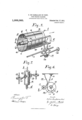
- Figure 1 represents diagrammatically the arrangement of the platen with regard to and in combination with a printing mechanism of any convenient type.
- Figs. 2 and 3 show in ground plan and side view the mechanism of the platen.
- Fig. 4 is an end View of the platen.
- Fig. 5 is a perspective view of the same.
- Fig. 6 is a detail.
- Fig. 7 represents a modification.
- the platen a is hollow and its bottom 6 which is at the end opposite the operator, has at its center a pivotwhich engages with a boring of a support 9.
- a tube It is centrally fixed on the inner surface of the bottom plate 6, this tube contains the long spiral spring (Z destined to cause the longitudinal displacement of the platen and the free end of said tube is telescoped in a second tube 2' which is guided in a central boring of the front bottom plate m of the platen, said boring having an extension at its upper end in which a longitudinal ridge 7c of tube 2' is guided, which prevents the rotation of tube 2' with regard to the platen a which thus is drawn along with tube 2' if the same rotates.
- the axle Z) of the platen is fixed centrally in the outer end of tube i and the toothed wheel a destined to revolve the platen is keyed uponsaid axle.
- WVheel a can be driven by any suitable mechanism; such for example as a spring, said toothed wheel being thrown in and out of gear by means of one of the numerous devices which are actually used with typewriting machines for this purpose.
- these devices are generally known and may be of any convenient construction, they have neither been represented in the drawings nor are they particularly described and it is clearly to be understood that said driving mechanisms do not form part of the present invention.
- the driving wheel a for the platen is animated by intermittent re evolving motions and stopped intermittently sutliciently long to permit the printing of a character.
- the platen a has a longitudinal slot 0 which extends over its entire length and behind which there is mounted in the cylinder a an axle p which carries a blade 9 adapted to bear against the inner surface of cylinder a under the influence of a draw-spring 7" which is arranged upon the outer surface of end plate 6 of the platen and fixed with its other end to the inner end of a lever 8 located in the cylinder and projecting with its other end 2? through the slot 0.
- This device for which there could be substituted any other device of known construction and serving for the same purpose, is destined to grip and hold the paper a.
- the paper sheet is inserted with its free edge into the slot 0, the lever 6 having been previously lifted so that the edge of the paper can easily penetrate between the blade 9 and the inner surface of the platen.
- the part of the paper sheet a which is inserted through slot 0 forms the margin, which can be of any width.
- the remaining part of the sheet hangs loosely along the outer surface of the platen.
- any suitable device for holding the paper upon the platen in connection with the device hereinbefore described such as for example, india-rubber strips, elastic rings or the like, but the use of such auxiliary devices is not obligatory.
- two gripping levers 2 and 3 (Fig. which are keyed upon a shaft 4 which is parallel with the axle of the platen a, said gripping levers having each at its upper end a hook 5 which is hinged to the lever in such a manner that it stops the steps y of the ladder if the same moves in the direction of the arrow (Fig. 5) giving way under the pressure of said steps if the ladder moves in opposite direction.
- a catch lever arm 6 is keyed.
- a toothed wheel 7 which is keyed upon shaft 6 meshes with a toothed wheel 8 which is of double the diameter of wheel 7 so that it revolves through one half revolution for every complete revolution of shaft Z).
- the tube 2' is slightly longer than the maximal height of the paper sheets to be used and the circumference of cylinder (6 has to be equal to the greatest length of the lines to be printed upon sheet u. If a fresh paper sheet is to be inserted, the platen a has to be in normal position so that the slot 0 is completely open. After the paper sheet has been inserted in the manner hereinbefdre described, the platen a is pushed back in the direction opposite to the arrow in Fig. 5 which can be easily done owing to the articulations of hooks 5 of the gripping levers. By this back-motion of the platen a the spring (Z is automatically put under tension and remains under tension as long as the paper sheet remains in position upon the platen.
- the slot 0 of the platen is brought either by hand or by means of the space bar to stand opposite the printing point and the .typewriting machine can be manipulated in the usual manner.
- the printing is accomplished by striking the finger keys causing the stepwise revolution of wheel 12 for the space of one tooth so that the platen will revolve, after a character has been printed, for a quantity equal to one space.
- the typewriting machine which has been hereinbefore described permits an increase the speed of writing owing to the fact that the shifting of the lines is effected automatically and that the paper at the end of each line is automatically presented in proper position for the beginning of a new line of print.
- the machine is further distinguished by a light and easy touch as the spring has to be put under tension only once for every page and not for every fresh line.
- An improved typewriting machine in which the paper is held upon a revoluble cylindrical platen, comprising in combination a cylindrical platen which is arranged horizontally and perpendicularly to the operator, the axle of said cylindrical platen consisting of two tubes telescoped the one in the other, a spring inclosed in said tubes for driving the cylindrical platen in longitudinal direction and means for connecting said cylindrical platen with said axle so that it revolves with the axle while being free to move upon the same in longitudinal direction, substantially as described and shown and for the purpose set forth.
- the device for the step-wise motion of said platen at. the end of each line consisting of an auxiliary shaft connected with the axle of said platen and oscillating at the end of every complete revolution of said platen,two gripping levers mounted upon said auxiliary shaft, articulated hookshaped upper ends of said levers, a guide piece for the platen composed of uniformly spaced steps which bearing against said gripping levers lock the platen, and a support for the platen fixed to the rear end of said guide piece, substantially as described and shown and for the purpose set forth.
Landscapes
- Handling Of Sheets (AREA)
Description
P. DE GARSALADE DU PONT.
TYPE WRITING MACHINE.
APPLIOATION FILED JULY 19, 1909. v 1,006,060. Patented 001121911.
7 o 2 SHEETS-SHEET 1.
, 15 6 wax-w,- My
P. DE CARSALADB DU FONT. Q
TYPE WRITING MACHINE.
APPLICATION rum: JULY 19, 1909.
1,006,060. Patented Oct. 17, 1911.
2 SHEETS-SHEET z.
6 i W flame 14514114481461? COLUMBIA PMNOGRAFH C0-.WASHINO tinrrnn srarns rarnnr ora ion;
PAUL DE GARSALADE DU FONT, OF PARIS, FRANCE, ASSIGNOR OF ONE-HALF TO GABRIEL ESCARRAS, OF PARIS, FRANCE.
TYPE-WRITING MACHINE.
ooaoeo.
To all whom it may concern:
Be it known that 1, PAUL DE CARSALADE DU Pour, a citizen of the French Republic, and resident of Paris, France, have invented certain new and useful Improvements in Type-Wvriting Machines, of which the following is a specification.
This invention relates to typewriting machines and more particularly to that type of machines in which the carriage whereon the paper is held instead of being animated with a reciprocating rectilinear motion, consists of a cylinder which revolves around its axle in such a manner that the lines, instead of following a rectilinear displacement of the carriage, develop along the cross section of said cylinder.
With the machines of known construction and of the same type, the platen or cylinder is vertically disposed, and upon completion of its rotation, it is moved upwardly or downwardly to present the paper for beginning a new line of print. WVith machines of this type it is further necessary to provide three complementary keys, of which one serves for causing the cylinder to complete its rotation for one line of print, the other for providing the required margin, and the third to longitudinally displace or shift the cylinder for the beginning of a fresh line of print; one of the auxiliary keys serving at the same time for putting under tension the spring which determines the rotation of the cylinder.
According to this invention, the platen whereon the paper is held is arranged horizontally and perpendicular to the operator; there is only one finger-key required for shifting the lines; the spring which causes the rotation of the cylinder is automatically put under tension when a fresh sheet of paper is inserted and it remains under ten sion as long as this paper is in the machine.
In the accompanying drawings the invention is illustrated.
Figure 1 represents diagrammatically the arrangement of the platen with regard to and in combination with a printing mechanism of any convenient type. Figs. 2 and 3 show in ground plan and side view the mechanism of the platen. Fig. 4 is an end View of the platen. Fig. 5 is a perspective view of the same. Fig. 6 is a detail. Fig. 7 represents a modification.
Referring to Fig. 1 of the accompanying Specification of Letters Patent.
Application filed July 19, 1809.
Patented Oct. 17, 1911.
Serial No. 508,510.
upon its axle b to present the paper for begmning a new line of print.
According to my invention the platen a is hollow and its bottom 6 which is at the end opposite the operator, has at its center a pivotwhich engages with a boring of a support 9. A tube It is centrally fixed on the inner surface of the bottom plate 6, this tube contains the long spiral spring (Z destined to cause the longitudinal displacement of the platen and the free end of said tube is telescoped in a second tube 2' which is guided in a central boring of the front bottom plate m of the platen, said boring having an extension at its upper end in which a longitudinal ridge 7c of tube 2' is guided, which prevents the rotation of tube 2' with regard to the platen a which thus is drawn along with tube 2' if the same rotates. The axle Z) of the platen is fixed centrally in the outer end of tube i and the toothed wheel a destined to revolve the platen is keyed uponsaid axle. WVheel a can be driven by any suitable mechanism; such for example as a spring, said toothed wheel being thrown in and out of gear by means of one of the numerous devices which are actually used with typewriting machines for this purpose. As these devices are generally known and may be of any convenient construction, they have neither been represented in the drawings nor are they particularly described and it is clearly to be understood that said driving mechanisms do not form part of the present invention. In the following description it is supposed that the driving wheel a for the platen is animated by intermittent re evolving motions and stopped intermittently sutliciently long to permit the printing of a character.
The platen a has a longitudinal slot 0 which extends over its entire length and behind which there is mounted in the cylinder a an axle p which carries a blade 9 adapted to bear against the inner surface of cylinder a under the influence of a draw-spring 7" which is arranged upon the outer surface of end plate 6 of the platen and fixed with its other end to the inner end of a lever 8 located in the cylinder and projecting with its other end 2? through the slot 0. This device, for which there could be substituted any other device of known construction and serving for the same purpose, is destined to grip and hold the paper a. The paper sheet is inserted with its free edge into the slot 0, the lever 6 having been previously lifted so that the edge of the paper can easily penetrate between the blade 9 and the inner surface of the platen. The part of the paper sheet a which is inserted through slot 0 forms the margin, which can be of any width. The remaining part of the sheet hangs loosely along the outer surface of the platen. There could be used any suitable device for holding the paper upon the platen in connection with the device hereinbefore described, such as for example, india-rubber strips, elastic rings or the like, but the use of such auxiliary devices is not obligatory. If the lever t is released after the insertion of the paper in the platen, blade 1 is pressed against the inner surface of the platen under the action of spring 7" whereby the paper sheet a is securely held in its position. The platen a is guided by means of guide rollers 21 whose axles are fixed on the frame of the machine and between which moves a removable ladder which is composed of two beams to and steps y, which is fixed at one end in the support 9 of the platen and which has at its other free end stops w destined to limit the travel of the platen. The distance between the steps y of the ladder determines the distance between the lines of print upon the paper. The ladder is fixed in support 9 in such a manner that it can be easily removed and replaced by another ladder if the distance between the lines of print has to be altered.
In connection with the ladder there are provided two gripping levers 2 and 3 (Fig. which are keyed upon a shaft 4 which is parallel with the axle of the platen a, said gripping levers having each at its upper end a hook 5 which is hinged to the lever in such a manner that it stops the steps y of the ladder if the same moves in the direction of the arrow (Fig. 5) giving way under the pressure of said steps if the ladder moves in opposite direction. Upon the front end of shaft 4 a catch lever arm 6 is keyed. A toothed wheel 7 which is keyed upon shaft 6 meshes with a toothed wheel 8 which is of double the diameter of wheel 7 so that it revolves through one half revolution for every complete revolution of shaft Z). Upon the rear surface of toothed wheel 8 two projecting ribs 10 and 11 are provided which are concentric with the axle 9 and the lever arm 6 is continuously in contact with one of said two ribs against which it is pressed by means of a spring 12. Owing to this arrangement the shaft & receives at each revolution of the platen a an oscillating motion so that the gripping lever 2 or 3 as the case may be which maintained the step y of the ladder against the action of spring (Z releases its step y so that the platen a is longitudinally displaced in the direction of the arrow under the action of spring (Z to be stopped again by the next step y coming in contact with the corresponding gripping lever.
If a fresh sheet of paper it has to be in serted before the platen a has arrived at the end of its travel, the stopping action of the gripping levers 2, 3 has to be put out of action; with this object in view said grip ping levers 2 and 3 are extended beyond their pivot and the extensions 13 are maintained apart the one from the other at the required distance by means of springs 14; arranged below the shaft at, a cam 15 being arranged between said extensions so that if the hand knob 16 is turned, the ends 13 of the gripping levers are moved away the one of the other and consequently the upper ends of said levers swing outward, so that the ladder can move in longitudinal direction without being stopped by. the gripping levers 2, 3.
The tube 2' is slightly longer than the maximal height of the paper sheets to be used and the circumference of cylinder (6 has to be equal to the greatest length of the lines to be printed upon sheet u. If a fresh paper sheet is to be inserted, the platen a has to be in normal position so that the slot 0 is completely open. After the paper sheet has been inserted in the manner hereinbefdre described, the platen a is pushed back in the direction opposite to the arrow in Fig. 5 which can be easily done owing to the articulations of hooks 5 of the gripping levers. By this back-motion of the platen a the spring (Z is automatically put under tension and remains under tension as long as the paper sheet remains in position upon the platen. Hereupon the slot 0 of the platen is brought either by hand or by means of the space bar to stand opposite the printing point and the .typewriting machine can be manipulated in the usual manner. The printing is accomplished by striking the finger keys causing the stepwise revolution of wheel 12 for the space of one tooth so that the platen will revolve, after a character has been printed, for a quantity equal to one space. When the line is concluded, shaft & oscillates automatically and the platen a moves forward to present the paper for the beginning of a new line and without requiring the operator to touch said platen.
There is required only one auxiliary finger key to conclude a line at any point of the width of the sheet and which merely serves to suppress the mechanism destined to stop the escapement Wheel 1 in order to permit that the platen completes rapidly its revolution.
With a machine of this type the insertion of a fresh sheet of paper after a certain time can be avoided as the rotation of the cylindrical platen a can be used for continually feeding an endless strip of paper 17 such for example as used in telegraphs (Fig. 7), said strip of paper 17 having the tendency to wind around an axle 18 which is under the influence of a spring, but owing to the two guide rollers 19 and 20 which press said strip upon the surface of the cylindrical platen, the strip can move only during the rotation of the platen. Thus, very long texts can be printed without changing the paper, whereby the speed of the writing is considerably increased.
The typewriting machine which has been hereinbefore described permits an increase the speed of writing owing to the fact that the shifting of the lines is effected automatically and that the paper at the end of each line is automatically presented in proper position for the beginning of a new line of print. The machine is further distinguished by a light and easy touch as the spring has to be put under tension only once for every page and not for every fresh line.
I claim 1. An improved typewriting machine in which the paper is held upon a revoluble cylindrical platen, comprising in combination a cylindrical platen which is arranged horizontally and perpendicularly to the operator, the axle of said cylindrical platen consisting of two tubes telescoped the one in the other, a spring inclosed in said tubes for driving the cylindrical platen in longitudinal direction and means for connecting said cylindrical platen with said axle so that it revolves with the axle while being free to move upon the same in longitudinal direction, substantially as described and shown and for the purpose set forth.
2. In an improved typewriting machine having a cylindrical platen arranged horizontally and perpendicularly to the operator and having a radial notch, two telescoped tubes forming the axle of said cylinder and a ridge upon the outer tube which engages with said notch, substantially as described and shown.
3. In an improved typewriting machine having a cylindrical platen arranged horizontally and perpendicularly to the operator, the device for the step-wise motion of said platen at. the end of each line consisting of an auxiliary shaft connected with the axle of said platen and oscillating at the end of every complete revolution of said platen,two gripping levers mounted upon said auxiliary shaft, articulated hookshaped upper ends of said levers, a guide piece for the platen composed of uniformly spaced steps which bearing against said gripping levers lock the platen, and a support for the platen fixed to the rear end of said guide piece, substantially as described and shown and for the purpose set forth.
In witness whereof I have hereunto set my hand in the presence of two witnesses.
PAUL DE GARSALADE DU PON'l.
Witnesses FERDINAND MUND, RUDOLPH GUY.
Copies of this patent may be obtained for five cents each, by addressing the Commissioner of Patents, Washington, I). O.
Priority Applications (1)
| Application Number | Priority Date | Filing Date | Title |
|---|---|---|---|
| US50851009A US1006060A (en) | 1909-07-19 | 1909-07-19 | Type-writing machine. |
Applications Claiming Priority (1)
| Application Number | Priority Date | Filing Date | Title |
|---|---|---|---|
| US50851009A US1006060A (en) | 1909-07-19 | 1909-07-19 | Type-writing machine. |
Publications (1)
| Publication Number | Publication Date |
|---|---|
| US1006060A true US1006060A (en) | 1911-10-17 |
Family
ID=3074374
Family Applications (1)
| Application Number | Title | Priority Date | Filing Date |
|---|---|---|---|
| US50851009A Expired - Lifetime US1006060A (en) | 1909-07-19 | 1909-07-19 | Type-writing machine. |
Country Status (1)
| Country | Link |
|---|---|
| US (1) | US1006060A (en) |
-
1909
- 1909-07-19 US US50851009A patent/US1006060A/en not_active Expired - Lifetime
Similar Documents
| Publication | Publication Date | Title |
|---|---|---|
| US1006060A (en) | Type-writing machine. | |
| US580014A (en) | Type-writing machine | |
| US725855A (en) | Type-writer. | |
| US343655A (en) | Type-writing machine | |
| US496297A (en) | Stenographic type-writing machine | |
| US633139A (en) | Type-writing machine. | |
| US573654A (en) | Type-writing machine | |
| US285141A (en) | Machine | |
| US557728A (en) | Type-writing machine | |
| US570545A (en) | Type-writing machine | |
| US1384407A (en) | Typewriting-machine | |
| US344627A (en) | cookson | |
| US426360A (en) | Type-writing machine | |
| US456808A (en) | Type writing machine | |
| US437090A (en) | Type-writing machine | |
| US1297020A (en) | Type-writer. | |
| US463910A (en) | myers | |
| US562337A (en) | Type-writing machine | |
| US474333A (en) | Type-writing machine | |
| US384142A (en) | Type-writing machine | |
| US393142A (en) | Type-writing machine | |
| US567937A (en) | And john conley | |
| US599187A (en) | Type-writing | |
| US457333A (en) | blickensderfer | |
| US537993A (en) | Type-writing machine |