US10058996B2 - Robot adaptive placement system with end-effector position estimation - Google Patents
Robot adaptive placement system with end-effector position estimation Download PDFInfo
- Publication number
- US10058996B2 US10058996B2 US14/944,603 US201514944603A US10058996B2 US 10058996 B2 US10058996 B2 US 10058996B2 US 201514944603 A US201514944603 A US 201514944603A US 10058996 B2 US10058996 B2 US 10058996B2
- Authority
- US
- United States
- Prior art keywords
- robot
- end effector
- substrate
- coordinates
- estimated
- Prior art date
- Legal status (The legal status is an assumption and is not a legal conclusion. Google has not performed a legal analysis and makes no representation as to the accuracy of the status listed.)
- Active
Links
- 239000012636 effector Substances 0.000 title claims abstract description 167
- 230000003044 adaptive effect Effects 0.000 title claims description 23
- 239000000758 substrate Substances 0.000 claims abstract description 89
- 230000033001 locomotion Effects 0.000 claims abstract description 50
- 238000000034 method Methods 0.000 claims abstract description 34
- 230000005540 biological transmission Effects 0.000 claims abstract description 18
- 230000000694 effects Effects 0.000 claims description 41
- 239000013598 vector Substances 0.000 claims description 15
- 238000005259 measurement Methods 0.000 claims description 12
- 238000004590 computer program Methods 0.000 claims description 6
- 238000010586 diagram Methods 0.000 description 40
- 238000004422 calculation algorithm Methods 0.000 description 38
- 230000007246 mechanism Effects 0.000 description 20
- 230000007704 transition Effects 0.000 description 11
- 238000001514 detection method Methods 0.000 description 9
- 238000012937 correction Methods 0.000 description 8
- 238000004364 calculation method Methods 0.000 description 6
- 238000012545 processing Methods 0.000 description 6
- 239000004065 semiconductor Substances 0.000 description 6
- 210000000245 forearm Anatomy 0.000 description 5
- 230000001133 acceleration Effects 0.000 description 3
- 230000008602 contraction Effects 0.000 description 3
- 230000001419 dependent effect Effects 0.000 description 3
- 230000004048 modification Effects 0.000 description 3
- 238000012986 modification Methods 0.000 description 3
- 230000003287 optical effect Effects 0.000 description 3
- 235000012431 wafers Nutrition 0.000 description 3
- 230000003190 augmentative effect Effects 0.000 description 2
- 238000005452 bending Methods 0.000 description 2
- 230000008859 change Effects 0.000 description 2
- 230000014509 gene expression Effects 0.000 description 2
- 230000008569 process Effects 0.000 description 2
- 230000001360 synchronised effect Effects 0.000 description 2
- XUIMIQQOPSSXEZ-UHFFFAOYSA-N Silicon Chemical compound [Si] XUIMIQQOPSSXEZ-UHFFFAOYSA-N 0.000 description 1
- 238000003491 array Methods 0.000 description 1
- 238000006243 chemical reaction Methods 0.000 description 1
- 238000011161 development Methods 0.000 description 1
- 230000018109 developmental process Effects 0.000 description 1
- 238000005516 engineering process Methods 0.000 description 1
- 230000003993 interaction Effects 0.000 description 1
- 239000000463 material Substances 0.000 description 1
- 239000002184 metal Substances 0.000 description 1
- 239000013307 optical fiber Substances 0.000 description 1
- 230000001902 propagating effect Effects 0.000 description 1
- 238000005070 sampling Methods 0.000 description 1
- 229910052710 silicon Inorganic materials 0.000 description 1
- 239000010703 silicon Substances 0.000 description 1
- 238000011144 upstream manufacturing Methods 0.000 description 1
- 210000000707 wrist Anatomy 0.000 description 1
Images


Classifications
-
- B—PERFORMING OPERATIONS; TRANSPORTING
- B25—HAND TOOLS; PORTABLE POWER-DRIVEN TOOLS; MANIPULATORS
- B25J—MANIPULATORS; CHAMBERS PROVIDED WITH MANIPULATION DEVICES
- B25J9/00—Programme-controlled manipulators
- B25J9/16—Programme controls
- B25J9/1628—Programme controls characterised by the control loop
- B25J9/1638—Programme controls characterised by the control loop compensation for arm bending/inertia, pay load weight/inertia
-
- B—PERFORMING OPERATIONS; TRANSPORTING
- B25—HAND TOOLS; PORTABLE POWER-DRIVEN TOOLS; MANIPULATORS
- B25J—MANIPULATORS; CHAMBERS PROVIDED WITH MANIPULATION DEVICES
- B25J9/00—Programme-controlled manipulators
- B25J9/10—Programme-controlled manipulators characterised by positioning means for manipulator elements
- B25J9/104—Programme-controlled manipulators characterised by positioning means for manipulator elements with cables, chains or ribbons
-
- B—PERFORMING OPERATIONS; TRANSPORTING
- B25—HAND TOOLS; PORTABLE POWER-DRIVEN TOOLS; MANIPULATORS
- B25J—MANIPULATORS; CHAMBERS PROVIDED WITH MANIPULATION DEVICES
- B25J9/00—Programme-controlled manipulators
- B25J9/10—Programme-controlled manipulators characterised by positioning means for manipulator elements
- B25J9/12—Programme-controlled manipulators characterised by positioning means for manipulator elements electric
- B25J9/126—Rotary actuators
-
- B—PERFORMING OPERATIONS; TRANSPORTING
- B25—HAND TOOLS; PORTABLE POWER-DRIVEN TOOLS; MANIPULATORS
- B25J—MANIPULATORS; CHAMBERS PROVIDED WITH MANIPULATION DEVICES
- B25J9/00—Programme-controlled manipulators
- B25J9/16—Programme controls
- B25J9/1602—Programme controls characterised by the control system, structure, architecture
- B25J9/1605—Simulation of manipulator lay-out, design, modelling of manipulator
-
- G—PHYSICS
- G05—CONTROLLING; REGULATING
- G05B—CONTROL OR REGULATING SYSTEMS IN GENERAL; FUNCTIONAL ELEMENTS OF SUCH SYSTEMS; MONITORING OR TESTING ARRANGEMENTS FOR SUCH SYSTEMS OR ELEMENTS
- G05B2219/00—Program-control systems
- G05B2219/30—Nc systems
- G05B2219/39—Robotics, robotics to robotics hand
- G05B2219/39176—Compensation deflection arm
-
- Y—GENERAL TAGGING OF NEW TECHNOLOGICAL DEVELOPMENTS; GENERAL TAGGING OF CROSS-SECTIONAL TECHNOLOGIES SPANNING OVER SEVERAL SECTIONS OF THE IPC; TECHNICAL SUBJECTS COVERED BY FORMER USPC CROSS-REFERENCE ART COLLECTIONS [XRACs] AND DIGESTS
- Y10—TECHNICAL SUBJECTS COVERED BY FORMER USPC
- Y10S—TECHNICAL SUBJECTS COVERED BY FORMER USPC CROSS-REFERENCE ART COLLECTIONS [XRACs] AND DIGESTS
- Y10S901/00—Robots
- Y10S901/02—Arm motion controller
- Y10S901/09—Closed loop, sensor feedback controls arm movement
Definitions
- the exemplary and non-limiting embodiments relate generally to a robot and, more particularly, to controlling movement of a robot.
- Semiconductor processing systems utilize one or more robotic manipulators to accurately deliver silicon wafers, referred to as substrates, to process modules, metrology stations, load locks and other suitable locations. Since the substrates may not be accurately positioned in the locations from which they are picked by the robot (initial misalignment), and because the robot end-effector typically does not provide a means of mechanically centering the substrate on the robot end-effector, external sensors are often utilized to detect the edges of the substrate during motion of the robot. This may be used by a control system to adjust the motion of the robot and subsequently deliver (place) the substrate accurately; regardless of the initial misalignment.
- control system typically captures the positions of the robot axes (motors, joints) when the edges of the substrate are detected by the sensors, and uses the resulting data along with the expected radius of the substrate and the coordinates of the sensors to either (1) determine the eccentricity of the substrate and use this information to compensate for the eccentricity when completing the place operation or (2) directly adjust the end point of the robot motion to place the substrate accurately regardless of the initial misalignment of the substrate.
- APS Adaptive Placement System
- the accuracy of the APS may be affected by mechanical imperfections, such as structural flexibilities and positioning errors in belt drives of the robotic manipulator, which may distort the relationship between the captured positions of the robot axes (motors, joints) and the corresponding actual positions of the robot end-effector.
- Typical structural flexibilities include a flexible frame of the drive section of the robot, flexible drive shafts (torsion and bending), flexible links, flexible joints, and elastic belts and bands, which tend to stretch under tension.
- Positioning errors in belt drives may result from hysteresis due to meshing errors between belt and pulley teeth.
- the accuracy of the APS may be affected by temperature changes in the operating environment of the robot. Temperature changes will cause thermal expansion and contraction of the robot's components, the structural frame that the robot is attached to, and the station where the substrate is delivered to. Temperature changes may be non-uniform so that different components of the system are at different temperatures and have different amounts of relative expansion or contraction. The temperature can also vary over time with different parts of the system changing at different rates. The consequence of this thermal deformation is inaccuracy in the robot's calculation of the position of its end effector. This calculation takes as its input the positions of the motors and uses pre-programmed knowledge of the geometry of the robot to calculate the position of the end effector. If the geometry of the robot is distorted by thermal effects, this calculation will be inaccurate.
- an example method comprises, based at least partially upon a command transmission to at least one motor of a robot, estimating deflection for at least one member of the robot during movement of the robot; based at least partially upon the estimated deflection, determining calculated end effector coordinates for an end effector of the robot; and based at least partially upon the calculated end effector coordinates, adjusting movement of the robot for placing a substrate, located on the robot, at a desired location.
- an example embodiment is provided in an apparatus comprising: at least one processor; and at least one non-transitory memory including computer program code, the at least one memory and the computer program code configured to, with the at least one processor, cause the apparatus to: based at least partially upon a command transmission to at least one motor of a robot, estimating deflection for at least one member of the robot during movement of the robot; based at least partially upon the estimated deflection, determining calculated end effector coordinates for an end effector of the robot; and based at least partially upon the calculated end effector coordinates, adjusting movement of the robot for placing a substrate, located on the robot, at a desired location.
- an example embodiment is provided in a non-transitory program storage device readable by a machine, tangibly embodying a program of instructions executable by the machine for performing operations, the operations comprising: based at least partially upon a command transmission to at least one motor of a robot, estimating deflection for at least one member of the robot during movement of the robot; based at least partially upon the estimated deflection, determining calculated end effector coordinates for an end effector of the robot; and based at least partially upon the calculated end effector coordinates, adjusting movement of the robot for placing a substrate, located on the robot, at a desired location.
- FIG. 1 is a diagram illustrating an example apparatus
- FIG. 2 is a diagram illustrating an example system
- FIG. 3 is a diagram illustrating an example apparatus
- FIG. 4 is a diagram illustrating an example apparatus
- FIG. 5A is a diagram illustrating an example apparatus
- FIG. 5B is a diagram illustrating an example apparatus
- FIG. 5C is a diagram illustrating an example apparatus
- FIG. 6 is a diagram illustrating an example system
- FIG. 7 is a diagram illustrating an example system
- FIG. 8 is a diagram illustrating an example system
- FIG. 9 is a diagram illustrating an example system
- FIG. 10 is a diagram illustrating an example system
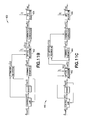
- FIGS. 11A-11C are diagrams illustrating example systems
- FIG. 12 is a diagram illustrating an example apparatus
- FIG. 13 is a diagram illustrating an example apparatus
- FIG. 14 is a diagram illustrating an example apparatus
- FIG. 15 is a diagram illustrating an example apparatus
- FIG. 16 is a diagram illustrating an example apparatus.
- FIG. 17 is a diagram illustrating an example controller.
- FIG. 1 there is shown a schematic top plan view of an example substrate processing apparatus having a substrate transport apparatus or robot system 100 .
- a substrate transport apparatus or robot system 100 there is shown a schematic top plan view of an example substrate processing apparatus having a substrate transport apparatus or robot system 100 .
- the present invention will be described with reference to the embodiments shown in the drawings, it should be understood that the present invention may be embodied in many forms of alternative embodiments. In addition, any suitable size, shape or type of materials or elements could be used.
- Typical structural flexibilities may include a flexible frame of the drive section of the robot, flexible drive shafts (torsion and bending), flexible links, flexible joints, and elastic belts and bands, which tend to stretch under tension. Positioning errors in belt drives may result from hysteresis due to meshing errors between belt and pulley teeth. It has been found that these manifest themselves as a memory-like phenomenon dependent on the moves performed by the robot. Features as described herein may use this memory-like phenomenon or otherwise.
- the structural flexibilities, positioning errors in belt drives and other mechanical imperfections may cause a discrepancy between the actual end-effector position and the end-effector position calculated conventionally based on the captured positions of the robot axes (motors, joints) using a rigid-body kinematic model. This discrepancy causes errors in inputs to various sensor calibration and eccentricity correction routines effecting the performance of the APS.
- the operations performed by the robot are repeatable (i.e., the robot follows the same motion paths and identical velocity profiles), the effects of the structural flexibilities and other mechanical imperfections may be inadvertently, and only partially, reduced by calibration procedures; the primary intention of which is to determine the locations of the sensors and to estimate their latency and hysteresis characteristics.
- the operations performed by the robot are not repeatable (including the cases where the robot follows substantially the same motion paths, but various motion profiles, such as due to different acceleration and/or speed settings for example), or if the effects of the structural flexibilities and other mechanical imperfections become significant (such as due to a growing size of the robot arms or an increasing size and weight of the substrates for example), the effects of the structural flexibilities need to be properly addressed in order to achieve the desired accuracy of the APS.
- the present disclosure describes two key features: (1) a position capture mechanism that takes into account flexible dynamics, positioning errors in belt drives as well as other mechanical imperfections of a robot and reduces their effects, and (2) an adaptive placement system which utilizes the above position capture mechanism.
- the present disclosure also describes a mechanical modification to the end effector of the robot that is designed to interact with the APS sensors in a way that allows the robot's control software to estimate the amount of thermal deformation present when the robot extends to place a substrate.
- FIG. 1 An example two-axis robotic arm 100 for a semiconductor processing system is depicted in a simplified diagrammatic form in FIG. 1 .
- the arm or robot 100 is connected or otherwise comprises a controller 10 .
- the controller 10 in this example, comprises a processor 12 and memory 14 .
- the memory 14 includes software 16 configured to control the robot 100 as further understood from the description below.
- the arm 100 consists of the first link 102 , second link 104 and third link 106 .
- An electric motor may be utilized to actuate the first link.
- Another electric motor may be used to actuate the second link via a 1:1 belt drive 108 .
- Another belt arrangement 110 may be employed to maintain radial orientation of the third link 106 regardless of the position of the first two links 102 , 104 . This may be achieved due to a 1:2 ratio between the pulley incorporated into the first link and the pulley connected to the third link.
- the third link 106 may form an end-effector that may carry a substrate 112 . In the diagram of FIG. 1 , the substrate 112 is shown positioned properly in its nominal location on the robot end-effector.
- An example robotic drive system is disclosed in U.S. Pat. No. 8,716,909 issued May 6, 2014 and entitled Robot with Heat Dissipating Stator which is hereby incorporated by reference herein in its entirety.
- a further example robotic drive system is disclosed in U.S. Pat. No. 9,149,936 issued Oct. 6, 2015 and entitled Robot with Unequal Link Length Arms which is hereby incorporated by reference herein in its entirety.
- the example arm 100 of FIG. 1 typically operates in a horizontal plane.
- An additional electromechanical arrangement may be utilized to move the entire arm in the vertical direction.
- the position of the example arm of FIG. 1 in a given horizontal plane may be uniquely defined by the angle of the first link, ⁇ lnk1 116 , and the angle of the second link, ⁇ lnk2 118 .
- the location of the center of the end-effector (a reference point on the end-effector that corresponds to the nominal location of the substrate carried by the robot) 120 may be described in a Cartesian coordinate system using an X-coordinate and a Y-coordinate, or in a polar coordinate system using a radial coordinate R and an angular coordinate T. Assuming that the example arm of FIG.
- l 1 denotes the joint-to-joint length of the first link
- l 2 is the joint-to-joint length of the second link
- l 3 represents the distance between the pivot point of the end-effector and the center of the end-effector.
- Equations (1) can be rewritten in the following form to describe the kinematic relationship between the measured axis coordinates (motor coordinates) and the end-effector coordinates (direct or forward kinematics):
- X l 1 cos ⁇ mtr1 +l 2 cos ⁇ mrt2 +l 3 cos [( ⁇ mtr1 + ⁇ mtr2 )/2]
- Y l 1 sin ⁇ mtr1 +l 2 sin ⁇ mtr2 +l 3 sin [( ⁇ mtr1 + ⁇ mtr2 )/2]
- ⁇ 3 ( ⁇ mtr1 + ⁇ mtr2 )/2 (2)
- ⁇ mtr1 denotes the angular position of motor 1 and ⁇ mtr2 is the angular position of motor 2 .
- positions ⁇ mtr1 and ⁇ mtr2 are measured in real time to facilitate motion control of the robot arm.
- the arm may move the substrate through one or more external sensors that may detect the leading and trailing edges of the substrate.
- the control system may capture the positions of the robot axes (motors) when the edges of the substrate are detected by the sensors and, utilizing Equation (2), may convert the captured positions to the corresponding positions of the center of the end-effector.
- the resulting data along with the nominal (expected) radius of the substrate and the coordinates of the sensors may then be utilized to either (1) determine the eccentricity of the substrate and use this information to compensate for the eccentricity when completing the place operation or (2) directly adjust the end point of the robot motion to place the substrate accurately regardless of the initial misalignment of the substrate.
- the adjustment to the end point of the robot motion may be applied either in an on-the-fly manner by modifying the existing trajectory of the robot, or through an additional move executed once the existing trajectory has been completed.
- a suitable APS system and apparatus is disclosed in U.S. Pat. No. 9,196,518 issued Nov. 24, 2015 and entitled Adaptive Placement System and Method which is hereby incorporated by reference herein in its entirety.
- Another suitable APS system and apparatus is disclosed in U.S. patent application Ser. No. 13/295,419 filed Jun. 4, 2014 and entitled Robot and Adaptive Placement System and Method which is hereby incorporated by reference herein in its entirety.
- ⁇ cmd represents a vector of commanded joint positions
- ⁇ denotes a vector of torques
- ⁇ rbt is a vector of measured joint positions
- Tj represents a trigger event j
- t j is the time of event T j
- ⁇ rbt (t j ) is a vector of measured joint positions at the time tj
- X rbt (t j ) is a vector of end-effector coordinates calculated based on ⁇ rbt (t j )
- D j represents constant data used by the APS algorithm (e.g., the nominal radius of the substrate or the coordinates of the sensors)
- X adj denotes a vector of adjusted coordinates of the end point of the robot motion
- t is time.
- vectors ⁇ cmd , ⁇ rbt , ⁇ rbt (t j ), X rbt (t j ) and X adj and should be treated as generalized coordinates (including distances and angles), and vector ⁇ should be interpreted as a vector of generalized forces (forces and torques).
- the system of FIG. 2 has control law 162 , robot 164 , capture mechanism 166 , forward kinematics 168 , APS algorithm 170 and feedback loop 172 .
- ⁇ cmd [ ⁇ cmd1 , ⁇ cmd2 ] T
- ⁇ rbt [ ⁇ mtr1 , ⁇ mtr2 ] T
- ⁇ [ ⁇ 1 , ⁇ 2 ] T
- the Forward Kinematics block 168 represents conversion of the captured joint positions to the corresponding end-effector coordinates.
- Equation (2) may be used for this purpose.
- the APS Algorithm block 170 represents calculation of the adjusted coordinates of the end point of the robot motion.
- the robot exhibits structural flexibilities, positioning errors in belt drives or other mechanical imperfections
- the calculated end-effector coordinates, X rbt (t j ) which are used in the APS algorithm, may not accurately reflect the actual position of the robot end-effector, resulting in poor performance of the APS.
- the effects of the flexibilities need to be taken into account, as described below in greater detail.
- FIG. 3 An example two-axis robotic arm 200 with longitudinally elastic belts 202 , 204 is depicted in a simplified diagrammatic form in FIG. 3 .
- the disclosed may be applied to drive arrangements with more or less belts or with more or less elastic elements.
- two links (upper arm 206 and forearm 208 ) and one end effector 210 with three rotary joints 212 , 214 , 216 are shown, more or less links, rotary joints or end effectors may be provided, for example with similar or different link lengths.
- the disclosed may be applied with respect to drives and arms as disclosed in PCT Publication WO 2014/113364 A1 having an international publication date of Jul.
- any suitable arm and drive may be provided.
- the longitudinal elasticity of the belts 202 , 204 is indicated by the symbols of springs in each of the branches of the belt arrangements.
- the arm 200 is depicted in its equilibrium position where the forces in the two branches of each of the two belt arrangements are balanced, and the substrate 220 is shown positioned properly in its nominal location on the robot end-effector 210 .
- ⁇ 2 222 is the error in the angular position of the second link and ⁇ 3 224 represents the error in the angular position of the third link.
- the resulting errors in the robot end-effector coordinates are shown as ⁇ X 226 and ⁇ Y 228 in FIG. 4 .
- the sensor 240 may detect the leading edge 242 of the substrate 220 , see diagram (a), and the trailing edge 244 of the substrate 220 , see diagram (b), as the robot 200 moves the substrate through the sensor.
- Black color in FIGS. 5 a and 5 b shows the example arm 200 of FIG. 3 with longitudinally elastic belts, grey color depicts an ideal representation of the arm, which is described by the conventional forward kinematic equations (2).
- the two detection events shown in diagrams (a) and (b) may be used to define two distinct points (typically in a coordinate system connected to the robot end-effector), which may be assumed to lie on the circumference of the substrate 220 . Given the size (radius or diameter) of the substrate 220 , these two points may be used to determine the location of the substrate on the robot end-effector, as illustrated in diagram FIG. 5 c.
- FIG. 5 c shows the positions of the substrate 220 on the robot end-effector calculated by the APS algorithm based on the detection events shown in FIGS. 5 a and 5 b .
- the black circle 250 represents the position of the substrate as calculated by the APS algorithm with proper estimation of the effects of the longitudinal flexibility of the belts.
- Point 1 corresponds to the point on the circumference (leading edge) of the substrate which was detected by the sensor by the detection event of FIG. 5 a
- point 2 corresponds to the point on the circumference (trailing edge) of the substrate detected by the sensor by the detection event of FIG. 5 b .
- the grey circle represents the position of the substrate on the robot end-effector as calculated by the APS algorithm using an ideal representation of the arm described by the conventional forward kinematic equations (2), which do not take into account the effects of the longitudinal flexibility of the belts.
- Point 3 corresponds to the point on the circumference (leading edge) of the substrate which was detected by the sensor by the detection event of FIG. 5 a
- point 4 corresponds to the point on the circumference (trailing edge) of the substrate detected by the sensor by the detection event of FIG. 5 b.
- an estimation algorithm may be used to take into account the errors, and the position capture mechanism may be modified as illustrated by the block diagram 300 of FIG. 6 .
- the estimation algorithm 302 may periodically calculate the estimated coordinates of the robot end-effector, the capture mechanism may capture the estimated coordinates of the robot end-effector when the edges of the substrate are detected by the sensors of the APS, and the resulting data along with the nominal (expected) radius of the substrate and the coordinates of the sensors may then be utilized to either (1) determine the eccentricity of the substrate and use this information to compensate for the eccentricity when completing the place operation or (2) directly adjust the end point of the robot motion to place the substrate accurately regardless of the initial misalignment of the substrate.
- the adjustment to the end point of the robot motion may be applied either in a manner while the robot is finishing its move by modifying the existing trajectory of the robot, or through an additional move executed once the existing trajectory has been completed.
- the estimation algorithm 302 may utilize motor positions 304 (typically measured directly, e.g., using position encoders), motor velocities 304 (either measured directly, e.g., using tachometers, or calculated from motor position data), motor accelerations 304 (typically calculated from velocity or position data), and the torques 306 applied by the motors (or equivalent quantities representative of the motor torques, such as motor currents, voltages or PWM duty cycles).
- the estimation algorithm may utilize the above inputs to calculate the estimated coordinates of the robot end-effector in a substantially continuous manner or periodically at a suitable frequency, for instance, at the sampling frequency of the motor position measurements or at the frequency at which the control law is executed.
- the estimation algorithm 302 in the block diagram of FIG. 6 may utilize the dynamic model of the robot, use a state observer or employ any other suitable technique to estimate the effects of the structural flexibilities on the position of the robot end-effector that cannot be measured directly by the sensors available in the robot.
- the estimation algorithm may also use a belt drive models to estimate the effects of belt positioning errors, and it may employ other suitable methods to estimate the effects of various other mechanical imperfections.
- the error 222 in the angular position of the second link (forearm) due to the longitudinal elasticity of the forearm belt drive may be estimated by direct application of the dynamic model of the robot arm.
- ⁇ 2 is the torque produced by motor 2
- k 2 represents the longitudinal stiffness of the belt arrangement that actuates the second link of the example robot arm
- r denotes the pulley radius of the belt arrangement that actuates the second link of the example robot arm.
- ⁇ umlaut over ( ⁇ ) ⁇ cmd2 and ⁇ dot over ( ⁇ ) ⁇ cmd2 are the angular acceleration and angular velocity of motor 2 respectively
- l 2 is the inertia moment of the rotating components of motor 2
- b 2 is the coefficient of friction for the motor 2 assembly
- the error 224 in the angular position of the third link (end-effector) due to this flexibility may be estimated using a reduced order state observer.
- Positioning errors in belt drives represent another phenomenon that may distort the relationship between motor positions and end-effector coordinates of a robot for semiconductor processing systems.
- belt positioning errors may result in additional contributions to the error in the angular position of the second link, ⁇ 2 , and the error in the angular position of the third link, ⁇ 3 , and, in turn, to the errors in the robot end-effector coordinates, ⁇ X and ⁇ Y.
- the dominant factor that often contributes to positioning errors in such a belt drive system is the bias in meshing between the belt and pulley teeth, which may manifest itself as a memory-like phenomenon dependent on the moves performed by the robot in the past.
- the primary causes for meshing bias are clearances between the belt and pulley teeth and friction at the belt-pulley contact regions. Clearances result in the belt teeth shifting between the walls of the pulley groove and friction results in residual contact forces and tooth deformation. The resulting belt positioning errors may be estimated.
- belt positioning errors may occur in other types of belt arrangements, including flat belts and metal bands, which are often used in robots for semiconductor processing systems.
- the above example methodology for estimation of positioning errors can be extended to such toothless belt drives. For instance, they can be treated as a limit case of a synchronous (toothed) belt arrangement in order to take into account the continuous nature of the belt-pulley interaction in a toothless belt drive system.
- the robot arm system may also be augmented with additional sensors attached to the structure that are designed so as to directly measure the flexibility in the structure during a robot move that includes an APS measurement.
- sensors could be, for example, strain gauges or accelerometers.
- the sensors could be attached to the robot at any location that is suitable, for example, the outside of any link, the inside of any link, on a pulley, or on a belt.
- the robot arm system may also be augmented with additional sensors that are not attached to the structure and make measurements using a non-contact technology.
- These non-contact sensors would also be designed so as to directly measure the flexibility in the structure during a robot move that includes an APS measurement.
- These sensors could be, for example, laser interferometers, laser range sensors, capacitive sensors, temperature sensors, optical light sensors, or cameras (for example 1-D or 2-D CCD arrays).
- the non-contact sensors could be installed within the robotic system (workspace) so as to take measurements at any suitable point on the robot arm such as the top, bottom, or sides of any link, or any other exposed surface that is suitable.
- auxiliary sensors described in this section may also be used in conjunction with one or more of the estimation algorithms described in previous sections.
- the estimation algorithms could be implemented in such a way so that they use the data from the auxiliary sensors solely, or use the data from the auxiliary sensors in conjunction with the data available from the robot control system including the measurements of generalized positions and generalized forces.
- the capture mechanism may be applied directly to the motor positions and torques, and these captured values may then serve as the inputs to the estimation algorithm. Refer to FIG. 7 for details.
- the end-effector coordinates may be calculated using conventional forward kinematic equations, which do not take into account structural flexibilities, belt positioning errors and other imperfections, and then corrected for the effects of these phenomena before being used in the APS algorithm.
- the correction may be calculated strictly based on the instantaneous values of the appropriate variables obtained from the capture mechanism.
- various variables may need to be processed periodically in order to achieve an accurate result.
- FIGS. 7-11 for details on the alternative embodiments.
- block diagram 350 in FIG. 7 shows estimation algorithm 352 being applied after the capture mechanism 354 .
- block diagram 360 in FIG. 8 shows estimation algorithm 362 being applied before the capture mechanism 364 with forward kinematics 366 upstream of capture mechanism 364 .
- FIGS. 9, 10 and 11 show alternative block diagrams 380 , 390 , 410 respectively.
- the capture mechanism may be applied directly to the motor positions and torques, ⁇ rbt and ⁇ , and the captured values, ⁇ rbt (t j ) and ⁇ (t j ), may then serve as the inputs to the estimation algorithm, as illustrated in FIG. 7 .
- the end-effector coordinates may be calculated using conventional forward kinematic equations, which do not take into account structural flexibilities, belt positioning errors and other imperfections, and then corrected for the effects of these phenomena before being used in the APS algorithm.
- the correction may be calculated strictly based on the instantaneous values of the appropriate variables obtained from the capture mechanism.
- various variables may need to be processed periodically in order to achieve an accurate result.
- motor positions ⁇ rbt may be processed using conventional forward kinematic equations 366 , which do not take into account structural flexibilities, belt positioning errors and other imperfections, to obtain ideal end-effector coordinates X rbt .
- the ideal end-effector coordinates X rbt along with motor torques ⁇ may then be used as inputs to an estimation algorithm 362 which may calculate estimated end-effector coordinates X est .
- the values X est (t j ) of the estimated end-effector coordinates X est determined by a capture mechanism 364 then may serve as inputs to the APS algorithm 368 .
- the capture mechanism 382 may be applied to the ideal end-effector coordinates X rbt and motor torques ⁇ , as depicted in the block diagram 380 of FIG. 9 .
- the resulting captured values, X rbt (t j ) and ⁇ (t j ) may then be processed by an estimation algorithm 384 to determine the corresponding estimated end-effector coordinates X est (t j ), which in turn may serve as inputs to the APS algorithm 386
- the capture mechanism 392 may be applied directly to motor positions ⁇ rbt and motor torques ⁇ , which scenario is illustrated in the block diagram 390 of FIG. 10 .
- the captured values ⁇ rbt (t j ) of motor positions ⁇ rbt may be converted using conventional forward kinematic equations 394 to the corresponding ideal end-effector coordinates X rbt (t j ), which may be fed along with the captured values ⁇ (t j ) of the motor torques ⁇ into an estimation algorithm 396 , producing the corresponding estimated end-effector coordinates X est (t j ).
- the estimated end-effector coordinates X est (t j ) may be used as inputs to the APS algorithm 398 .
- motor positions ⁇ rbt may be processed using conventional forward kinematic equations 412 , which do not take into account structural flexibilities, belt positioning errors and other imperfections, to obtain ideal end-effector coordinates X rbt .
- motor positions ⁇ rbt along with motor torques ⁇ may be used in an estimation algorithm 414 to produce corrections ⁇ X , which then may be applied to ideal end-effector coordinates X rbt to compensate for structural flexibilities, belt positioning errors and other imperfections, as indicated by the “kinematics correction” block 416 in FIG. 11 .
- the corrected end-effector coordinates X est may be fed through a capture mechanism 418 to the APS algorithm 420 .
- system 430 is shown in FIG. 11B where the position capture mechanism 432 may be applied to ideal end-effector coordinates X rbt and to corrections ⁇ X , and the resulting values, X rbt (t j ) and ⁇ X (t j ), and may be used to calculate the corresponding values of corrected end-effector coordinates, X est (t j ), which may then be fed to the APS algorithm 434 .
- the capture mechanism 442 may be applied directly to motor positions ⁇ rbt and motor torques ⁇ , which case is illustrated in the block diagram 440 of FIG. 11C .
- the resulting values ⁇ rbt (t j ) of motor positions ⁇ rbt may be converted using conventional forward kinematic equations 444 to the corresponding ideal end-effector coordinates X rbt (t j ).
- the captured values ⁇ rbt (t j ) and ⁇ (t j ) may be used to calculate the corresponding values of corrections ⁇ X (t j ), which may be applied to the corresponding ideal end-effector coordinates, X rbt (t j ), to calculate the corresponding estimated end-effector coordinates, X est (t j ).
- the values X est (t j ) may be fed to the APS algorithm 446 .
- ⁇ 2 ( t j ) is the error in the angular position of the second link
- ⁇ 2 (t j ) is the torque produced by motor 2 , both at the time t j of capture event j
- k 2 represents the longitudinal stiffness of the belt arrangement that actuates the second link of the example robot arm
- r denotes the pulley radius of the belt arrangement that actuates the second link of the example robot arm.
- T corrected (t j ) is the corrected angular coordinate of the robot end-effector
- T(t j ) is the angular coordinate of the end-effector calculated using conventional kinematic equations
- R corrected (tj) is the corrected radial coordinate of the robot end-effector
- R(t j ) is the radial coordinate of the end-effector calculated using conventional kinematic equations, all at the time t j of capture event j.
- l denotes the joint-to-joint length of the first and second links of the robot arm (in this particular example, the two links are assumed to be of the same length)
- l 3 represents the distance between the pivot point of the end-effector and the center of the end-effector.
- the estimation algorithm in the block diagram of FIG. 6 (and its derivatives described earlier in this section) is not limited to the example arm of FIG. 3 , and may be designed to estimate the coordinates of the robot end-effector regardless of the number of axes of the robot or the type of the mechanism of the robot arm.
- the technique may be extended to robots with multiple end-effectors.
- the estimation algorithm may be employed to estimate effects of various other mechanical imperfections and physical phenomena that may distort the relationship between the measured robot axis positions and the coordinates of the robot end-effector, which typically cannot be measured directly. This includes, but is not limited to, flexibilities in gearboxes, meshing errors in gearboxes, flexibilities in robot joints, clearances in robot joints, frictional effects and thermal effects (expansion and contraction of components due to differences or changes in temperature).
- the estimation algorithm may also be used to estimate the velocity of the robot end-effector (including the magnitude and direction of the translational component and the angular component of the velocity of the end-effector). This information may be utilized in various calibration and compensation algorithms as part of the APS.
- the APS algorithm in the block diagram of FIG. 6 may include various calibration and compensation algorithms including, but not limited to, compensation for sensor latency, compensation for sensor hysteresis, detection of substrate breakage and detection of alignment fiducials, which may be present at the circumference of some substrates.
- FIG. 12 shows an illustration of a robot 450 (SCARA type in this example).
- SCARA SCARA type in this example.
- the APS sensors 456 , 458 are tripped by the edges of the wafer and the robot positions are captured at those instants to enable the APS station placement correction calculation.
- FIG. 12 provides the addition of two triangular flags 460 , 462 attached to the end effector. Ideally, these will be located as close to the substrate as possible, but alternative placements will also work.
- the flags 460 , 462 are positioned so that they will cause additional transitions of the APS sensors during the extend to the station.
- the robot positions captured from these additional APS sensor transitions may be used to estimate the amount of thermal deformation present in that moment. It is assumed that a calibration of APS is performed with the system in a known thermal state where the nominal geometry is known accurately.
- flags 460 , 462 are shown as being triangular in shape, any suitable shape may be provided to determine the actual position of the end effector using the sensors in combination with known or calibrated sensor positions and known or calibrated flag positions with respect to the end effector center or any suitable reference location on the end effector, arm or otherwise.
- flags 460 , 462 are described in reference to detecting and correcting for thermal deformation, in alternate aspects, the use of flags 460 , 462 in combination with the sensors and encoder captured positions at the flag/sensor transitions may be used otherwise, for example, for the detection of the actual location of the end effector as a replacement of or to compliment the estimation algorithm described above or for any other suitable use.
- the radial position of the robot can be stretched due to increased temperature of the end effector.
- the APS transitions will occur slightly earlier during the extend motion as shown in FIG. 13 due to the deformed state 480 as opposed to the un deformed state 482 .
- the sensor transitions associated with the flags on the end effector can be used to estimate the amount of thermal expansion in the radial direction. This is done by a direct comparison between the radial position as captured during the calibration procedure performed at the nominal temperature to the radial position captured during the present extend move to place a substrate. If the end effector expands radially due to increased temperature, the captured radial location during the transitions on the leading edge of the flag will have a smaller value because the sensor is tripped earlier than normal.
- the tangential position of the robot can be shifted due to increased temperature of the forearm link as shown in FIG. 14 due to the deformed state 510 as opposed to the un deformed state 512 .
- the leading edge transition of the flag is unchanged, but the trailing edge transitions are earlier on one side and later on the opposite side.
- Combinations of radial and tangential distortion can be estimated by combining the end effector flag APS sensor transition data from the leading and trailing edges. An example illustration of this is shown in FIG. 15 showing the deformed state 530 as opposed to the un deformed state 532 .
- Thermal deformation that results in change to the orientation of the end effector can also be detected using this method; see FIG. 16 showing the deformed state 550 as opposed to the un deformed state 552 .
- FIG. 16 shows the deformed state 550 as opposed to the un deformed state 552 .
- the distortion of the robot's geometry can be calculated or estimated by formulae that will be specific to the type of robot in use.
- the updated geometry can then be used for the kinematics calculations, thus improving the accuracy of substrate placement.
- a method comprising: based at least partially upon a command transmission to at least one motor of a robot, estimating deflection for at least one member of the robot during movement of the robot; based at least partially upon the estimated deflection, determining calculated end effector coordinates for an end effector of the robot; and based at least partially upon the calculated end effector coordinates, adjusting movement of the robot for placing a substrate, located on the robot, at a desired location.
- the command transmission comprises a command torque transmission which is transmitted to the at least one motor to generate a predetermined torque vector.
- the estimated deflection for the at least one member of the robot comprises at least one of: a flexible frame member of a drive section of the robot, a flexible drive shaft of the at least one motor, a flexible link of an arm of the robot, a flexible joint between links of the arm of the robot, and an elastic belt or band of the arm of the robot.
- a method where the estimating comprises at least one of: estimation of flexibility effects using dynamic modeling, estimation of flexibility effects using a state observer, estimation of belt positioning error effects, and direct measurement of flexibility effects using at least one auxiliary sensor.
- a method where the estimating of the deflection is based, at least partially, upon location information from at least one sensor regarding at least one of: a portion of the robot, and a substrate carried by the robot.
- a method where the adjusting of movement of the robot is based upon a combination of the calculated end effector coordinates and the location information from the at least one sensor.
- a method where the adjusting of movement of the robot is further based upon forward kinematics determination of the end effector which subsequently provides modified estimated end effector coordinates to an adaptive placement system (APS) to determine adjusted end effector coordinates to be used to drive the at least one motor of the robot.
- APS adaptive placement system
- adjusting movement of the robot comprises providing the calculated end effector coordinates to an adaptive placement system (APS) to determine adjusted end effector coordinates to be used to drive the at least one motor of the robot.
- APS adaptive placement system
- a method is provided where the calculated end effector coordinates are provided to a robot location sensing system and/or to a substrate location sensing system, which subsequently provides modified estimated end effector coordinates to an adaptive placement system (APS) to determine adjusted end effector coordinates to be used to drive the at least one motor of the robot.
- APS adaptive placement system
- an apparatus comprising: at least one processor; and at least one non-transitory memory including computer program code, the at least one memory and the computer program code configured to, with the at least one processor, cause the apparatus to: based at least partially upon a command transmission to at least one motor of a robot, estimating deflection for at least one member of the robot during movement of the robot; based at least partially upon the estimated deflection, determining calculated end effector coordinates for an end effector of the robot; and based at least partially upon the calculated end effector coordinates, adjusting movement of the robot for placing a substrate, located on the robot, at a desired location.
- an apparatus where the command transmission comprises a command torque transmission which is transmitted to the at least one motor to generate a predetermined torque vector.
- an apparatus where the estimated deflection for the at least one member of the robot comprises at least one of: a flexible frame member of a drive section of the robot, a flexible drive shaft of the at least one motor, a flexible link of an arm of the robot, a flexible joint between links of the arm of the robot, and an elastic belt or band of the arm of the robot.
- an apparatus where the estimating comprises at least one of: estimation of flexibility effects using dynamic modeling, estimation of flexibility effects using a state observer, estimation of belt positioning error effects, and direct measurement of flexibility effects using at least one auxiliary sensor.
- an apparatus where the estimating of the deflection is based, at least partially, upon location information from at least one sensor regarding at least one of: a portion of the robot, and a substrate carried by the robot.
- an apparatus where the adjusting of movement of the robot is based upon a combination of the calculated end effector coordinates and the location information from the at least one sensor.
- an apparatus where the adjusting of movement of the robot is further based upon forward kinematics determination of the end effector which subsequently provides modified estimated end effector coordinates to an adaptive placement system (APS) to determine adjusted end effector coordinates to be used to drive the at least one motor of the robot.
- APS adaptive placement system
- an apparatus where the adjusting of the movement of the robot comprises providing the calculated end effector coordinates to an adaptive placement system (APS) to determine adjusted end effector coordinates to be used to drive the at least one motor of the robot.
- APS adaptive placement system
- an apparatus where the calculated end effector coordinates are provided to a robot location sensing system and/or to a substrate location sensing system, which subsequently provides modified estimated end effector coordinates to an adaptive placement system (APS) to determine adjusted end effector coordinates to be used to drive the at least one motor of the robot.
- APS adaptive placement system
- a non-transitory program storage device readable by a machine, tangibly embodying a program of instructions executable by the machine for performing operations, the operations comprising: based at least partially upon a command transmission to at least one motor of a robot, estimating deflection for at least one member of the robot during movement of the robot; based at least partially upon the estimated deflection, determining calculated end effector coordinates for an end effector of the robot; and based at least partially upon the calculated end effector coordinates, adjusting movement of the robot for placing a substrate, located on the robot, at a desired location.
- an apparatus comprising means, based at least partially upon a command transmission to at least one motor of a robot, for estimating deflection for at least one member of the robot during movement of the robot; means, based at least partially upon the estimated deflection, for determining calculated end effector coordinates for an end effector of the robot; and means, based at least partially upon the calculated end effector coordinates, for adjusting movement of the robot for placing a substrate, located on the robot, at a desired location.
- the computer readable medium may be a computer readable signal medium or a non-transitory computer readable storage medium.
- a non-transitory computer readable storage medium does not include propagating signals and may be, for example, but not limited to, an electronic, magnetic, optical, electromagnetic, infrared, or semiconductor system, apparatus, or device, or any suitable combination of the foregoing.
- the computer readable storage medium would include the following: an electrical connection having one or more wires, a portable computer diskette, a hard disk, a random access memory (RAM), a read-only memory (ROM), an erasable programmable read-only memory (EPROM or Flash memory), an optical fiber, a portable compact disc read-only memory (CD-ROM), an optical storage device, a magnetic storage device, or any suitable combination of the foregoing.
Landscapes
- Engineering & Computer Science (AREA)
- Robotics (AREA)
- Mechanical Engineering (AREA)
- Automation & Control Theory (AREA)
- Manipulator (AREA)
- Container, Conveyance, Adherence, Positioning, Of Wafer (AREA)
Abstract
Description
X=l 1 cos θlnk1 +l 2 cos θlnk2 +l 3 cos [(θlnk1+θlnk2)/2]
Y=l 1 sin θlnk1 +l 2 sin θlnk2 +l 3 sin [(θlnk1+θlnk2)/2]
θ3=(θlnk1+θlnk2)/2 (1)
X=l 1 cos θmtr1 +l 2 cos θmrt2 +l 3 cos [(θmtr1+θmtr2)/2]
Y=l 1 sin θmtr1 +l 2 sin θmtr2 +l 3 sin [(θmtr1+θmtr2)/2]
θ3=(θmtr1+θmtr2 )/2 (2)
X=l 1 cos θmtr1 +l 2 cos(θmtr2+Δ2)+l 3 cos [(θmtr1+θmtr2+Δ2)/2+Δ3]
Y=l 1 sin θmtr1 +l 2 sin(θmtr2++Δ2)+l 3 sin [(θmtr1+θmtr2+Δ2)/2+Δ3]
θ3=(θmtr1+θmtr2+Δ2)/2+Δ3 (3)
Δ2=−τ2/(k 2 r) (4)
τ2 =l 2{umlaut over (θ)}cmd2 +b 2{dot over (θ)}cmd2 −k 2(r·Δ 2) (5)
The effect of the longitudinal elasticity of the belt on the angular position of the second link is then:
Δ2=(l 2{umlaut over (θ)}cmd2 +b 2{dot over (θ)}cmd2−τ2)/(k 2 r) (6)
Δ2(t j)=−τ2(t j)/(k 2 r) (7)
T corrected(t j)=T(tj)+Δ2(t j)/2 (8)
R corrected(t j)=2l cos [α(t j)−Δ2(t j)/2]+l 3 (9)
where
α(t j)=a cos {[R(t j)−l 3]/(2l)} (10)
Claims (18)
Priority Applications (1)
| Application Number | Priority Date | Filing Date | Title |
|---|---|---|---|
| US14/944,603 US10058996B2 (en) | 2014-11-18 | 2015-11-18 | Robot adaptive placement system with end-effector position estimation |
Applications Claiming Priority (2)
| Application Number | Priority Date | Filing Date | Title |
|---|---|---|---|
| US201462081209P | 2014-11-18 | 2014-11-18 | |
| US14/944,603 US10058996B2 (en) | 2014-11-18 | 2015-11-18 | Robot adaptive placement system with end-effector position estimation |
Publications (2)
| Publication Number | Publication Date |
|---|---|
| US20160136812A1 US20160136812A1 (en) | 2016-05-19 |
| US10058996B2 true US10058996B2 (en) | 2018-08-28 |
Family
ID=55960894
Family Applications (1)
| Application Number | Title | Priority Date | Filing Date |
|---|---|---|---|
| US14/944,603 Active US10058996B2 (en) | 2014-11-18 | 2015-11-18 | Robot adaptive placement system with end-effector position estimation |
Country Status (5)
| Country | Link |
|---|---|
| US (1) | US10058996B2 (en) |
| JP (1) | JP6754771B2 (en) |
| KR (1) | KR102469258B1 (en) |
| CN (1) | CN107107336B (en) |
| WO (1) | WO2016081459A1 (en) |
Cited By (9)
| Publication number | Priority date | Publication date | Assignee | Title |
|---|---|---|---|---|
| US10651067B2 (en) * | 2017-01-26 | 2020-05-12 | Brooks Automation, Inc. | Method and apparatus for substrate transport apparatus position compensation |
| US10751883B2 (en) * | 2018-08-16 | 2020-08-25 | Mitutoyo Corporation | Robot system with supplementary metrology position coordinates determination system |
| US10871366B2 (en) | 2018-08-16 | 2020-12-22 | Mitutoyo Corporation | Supplementary metrology position coordinates determination system for use with a robot |
| US10913156B2 (en) | 2018-09-24 | 2021-02-09 | Mitutoyo Corporation | Robot system with end tool metrology position coordinates determination system |
| US11002529B2 (en) | 2018-08-16 | 2021-05-11 | Mitutoyo Corporation | Robot system with supplementary metrology position determination system |
| US11745354B2 (en) | 2018-08-16 | 2023-09-05 | Mitutoyo Corporation | Supplementary metrology position coordinates determination system including an alignment sensor for use with a robot |
| US11964831B2 (en) | 2019-02-14 | 2024-04-23 | Persimmon Technologies Corporation | Magnetically guided material handling robot |
| US12174005B2 (en) | 2021-12-27 | 2024-12-24 | Mitutoyo Corporation | Metrology system with position and orientation tracking utilizing light beams |
| US12455158B2 (en) | 2023-12-15 | 2025-10-28 | Mitutoyo Corporation | Metrology system with high speed position and orientation tracking mode |
Families Citing this family (19)
| Publication number | Priority date | Publication date | Assignee | Title |
|---|---|---|---|---|
| JP6918770B2 (en) | 2015-07-13 | 2021-08-11 | ブルックス オートメーション インコーポレイテッド | On-the-fly automatic wafer centering method and equipment |
| US10580681B2 (en) * | 2016-07-10 | 2020-03-03 | Yaskawa America Inc. | Robotic apparatus and method for transport of a workpiece |
| JP6862854B2 (en) * | 2017-01-27 | 2021-04-21 | セイコーエプソン株式会社 | Control device, robot system and screw tightening torque setting method |
| US20180348730A1 (en) * | 2017-06-01 | 2018-12-06 | X Development Llc | Automatic Generation of Toolpaths |
| US11088004B2 (en) | 2018-01-30 | 2021-08-10 | Brooks Automation, Inc. | Automatic wafer centering method and apparatus |
| WO2019163116A1 (en) * | 2018-02-26 | 2019-08-29 | 三菱電機株式会社 | Correction function-generating device, robot control system, and robot system |
| WO2020009919A1 (en) * | 2018-07-03 | 2020-01-09 | Persimmon Technologies, Corp. | System and method for detection and correction of robot payload position |
| JP6898366B2 (en) * | 2019-01-22 | 2021-07-07 | ファナック株式会社 | Robot device and thermal displacement estimation device |
| US11626305B2 (en) * | 2019-06-25 | 2023-04-11 | Applied Materials, Inc. | Sensor-based correction of robot-held object |
| CN115362051A (en) * | 2020-02-10 | 2022-11-18 | 柿子技术公司 | Vacuum environment robot with distributed actuators |
| CN113370203A (en) * | 2020-03-10 | 2021-09-10 | 固高科技(深圳)有限公司 | Robot control method, robot control device, computer device, and storage medium |
| JP7553191B2 (en) * | 2020-08-31 | 2024-09-18 | 東京エレクトロン株式会社 | Substrate transport system control method and substrate transport system |
| JP7433179B2 (en) * | 2020-09-17 | 2024-02-19 | 東京エレクトロン株式会社 | Control method and substrate transfer system |
| EP4214026A4 (en) * | 2020-09-18 | 2024-06-05 | Abb Schweiz Ag | METHOD AND DEVICE FOR ADJUSTING A ROBOT SYSTEM |
| JP7624893B2 (en) * | 2021-07-14 | 2025-01-31 | 東京エレクトロン株式会社 | Substrate transport method and substrate transport system |
| US12201377B2 (en) * | 2021-11-01 | 2025-01-21 | Mazor Robotics Ltd. | Arm movement safety layer |
| EP4533029A4 (en) * | 2022-05-26 | 2026-01-21 | Abb Schweiz Ag | METHOD AND DEVICE FOR CALIBRINGING THE THERMAL DRIFT OF A ROBOT |
| CN115319800B (en) * | 2022-09-14 | 2025-07-01 | 西北工业大学 | A design method for a time-predetermined controller of a dual-joint robotic arm |
| CN117124063B (en) * | 2023-10-27 | 2024-02-13 | 苏州工业园区耐斯达自动化技术有限公司 | Screw-screwing balance arm and screw-screwing position control method thereof |
Citations (55)
| Publication number | Priority date | Publication date | Assignee | Title |
|---|---|---|---|---|
| US4449885A (en) | 1982-05-24 | 1984-05-22 | Varian Associates, Inc. | Wafer transfer system |
| US4507078A (en) | 1983-03-28 | 1985-03-26 | Silicon Valley Group, Inc. | Wafer handling apparatus and method |
| US4523985A (en) | 1983-12-22 | 1985-06-18 | Sputtered Films, Inc. | Wafer processing machine |
| US4770590A (en) | 1986-05-16 | 1988-09-13 | Silicon Valley Group, Inc. | Method and apparatus for transferring wafers between cassettes and a boat |
| US4819167A (en) | 1987-04-20 | 1989-04-04 | Applied Materials, Inc. | System and method for detecting the center of an integrated circuit wafer |
| US4884941A (en) * | 1987-03-30 | 1989-12-05 | Regents Of The University Of Minnesota | Active compliant end-effector with force, angular position, and angular velocity sensing |
| US4955780A (en) | 1987-10-20 | 1990-09-11 | Fujitsu Limited | Wafer positioning apparatus |
| US5418441A (en) * | 1990-12-28 | 1995-05-23 | Fanuc, Ltd. | Deflection correcting method for a robot |
| US5483138A (en) | 1992-11-12 | 1996-01-09 | Applied Materials, Inc. | System and method for automated positioning of a substrate in a processing chamber |
| US5546179A (en) | 1994-10-07 | 1996-08-13 | Cheng; David | Method and apparatus for mapping the edge and other characteristics of a workpiece |
| US5563798A (en) | 1994-04-05 | 1996-10-08 | Applied Materials, Inc. | Wafer positioning system |
| US5682795A (en) * | 1995-07-10 | 1997-11-04 | Smart Machines | Robotic joint using metal bands |
| US5690744A (en) | 1995-06-07 | 1997-11-25 | Varian Associates, Inc. | Wafer orientation alignment system |
| US5706201A (en) | 1996-05-07 | 1998-01-06 | Fortrend Engineering Corporation | Software to determine the position of the center of a wafer |
| US5704062A (en) | 1996-10-21 | 1998-01-06 | Caroleo; Rudolph | Sun visor |
| US5980194A (en) | 1996-07-15 | 1999-11-09 | Applied Materials, Inc. | Wafer position error detection and correction system |
| US6085125A (en) * | 1998-05-11 | 2000-07-04 | Genmark Automation, Inc. | Prealigner and planarity teaching station |
| US6198976B1 (en) | 1998-03-04 | 2001-03-06 | Applied Materials, Inc. | On the fly center-finding during substrate handling in a processing system |
| US6225012B1 (en) * | 1994-02-22 | 2001-05-01 | Nikon Corporation | Method for positioning substrate |
| US6304051B1 (en) | 1999-03-15 | 2001-10-16 | Berkeley Process Control, Inc. | Self teaching robotic carrier handling system |
| US6327517B1 (en) | 2000-07-27 | 2001-12-04 | Applied Materials, Inc. | Apparatus for on-the-fly center finding and notch aligning for wafer handling robots |
| US6405101B1 (en) | 1998-11-17 | 2002-06-11 | Novellus Systems, Inc. | Wafer centering system and method |
| US6464448B1 (en) * | 1998-09-01 | 2002-10-15 | Brooks Automation, Inc. | Substrate transport apparatus |
| US6489741B1 (en) * | 1998-08-25 | 2002-12-03 | Genmark Automation, Inc. | Robot motion compensation system |
| US6502054B1 (en) | 1999-11-22 | 2002-12-31 | Lam Research Corporation | Method of and apparatus for dynamic alignment of substrates |
| US6571657B1 (en) * | 1999-04-08 | 2003-06-03 | Applied Materials Inc. | Multiple blade robot adjustment apparatus and associated method |
| US6629053B1 (en) | 1999-11-22 | 2003-09-30 | Lam Research Corporation | Method and apparatus for determining substrate offset using optimization techniques |
| US20030223057A1 (en) * | 2002-02-06 | 2003-12-04 | Ramsey Craig C. | Wireless substrate-like sensor |
| US6760976B1 (en) | 2003-01-15 | 2004-07-13 | Novellus Systems, Inc. | Method for active wafer centering using a single sensor |
| US20040167743A1 (en) | 2002-12-20 | 2004-08-26 | Martin Hosek | System and method for on-the-fly eccentricity recognition |
| US20050224902A1 (en) * | 2002-02-06 | 2005-10-13 | Ramsey Craig C | Wireless substrate-like sensor |
| US20050233770A1 (en) * | 2002-02-06 | 2005-10-20 | Ramsey Craig C | Wireless substrate-like sensor |
| US7008802B2 (en) | 2001-05-29 | 2006-03-07 | Asm America, Inc. | Method and apparatus to correct water drift |
| US20060130750A1 (en) * | 2004-12-22 | 2006-06-22 | Applied Materials, Inc. | Cluster tool architecture for processing a substrate |
| US7129694B2 (en) * | 2002-05-23 | 2006-10-31 | Applied Materials, Inc. | Large substrate test system |
| US20070264106A1 (en) * | 2003-11-10 | 2007-11-15 | Van Der Meulen Peter | Robotic components for semiconductor manufacturing |
| US7433759B2 (en) | 2004-07-22 | 2008-10-07 | Applied Materials, Inc. | Apparatus and methods for positioning wafers |
| US20090038258A1 (en) * | 2005-12-30 | 2009-02-12 | Gold Wing Nominees Pty Ltd | Automated brick laying system for constructing a building from a plurality of bricks |
| US20090232630A1 (en) * | 2008-03-13 | 2009-09-17 | John Roberts | Tendon enhanced end effector |
| US20090243413A1 (en) * | 2007-06-27 | 2009-10-01 | Brooks Automation, Inc. | Robot drive with magnetic spindle bearings |
| US20100081095A1 (en) * | 2008-09-22 | 2010-04-01 | Nikon Corporation | Movable body apparatus, movable body drive method, exposure apparatus, exposure method, and device manufacturing method |
| US20100157275A1 (en) * | 2008-12-19 | 2010-06-24 | Nikon Corporation | Exposure apparatus, exposure method, and device manufacturing method |
| US7792350B2 (en) | 2003-11-10 | 2010-09-07 | Brooks Automation, Inc. | Wafer center finding |
| US7933665B2 (en) | 2002-05-30 | 2011-04-26 | Rorze Corporation | Method and system for teaching reference position of semiconductor wafer in automated wafer handling manufacturing equipment |
| US7963736B2 (en) | 2008-04-03 | 2011-06-21 | Asm Japan K.K. | Wafer processing apparatus with wafer alignment device |
| US8224607B2 (en) | 2007-08-30 | 2012-07-17 | Applied Materials, Inc. | Method and apparatus for robot calibrations with a calibrating device |
| US20120249992A1 (en) * | 2011-03-31 | 2012-10-04 | Tokyo Electron Limited | Substrate transfer apparatus and substrate transfer method |
| US20130041509A1 (en) * | 2011-01-31 | 2013-02-14 | Toyota Jidosha Kabushiki Kaisha | Articulated arm robot, control method and control program |
| US20130071218A1 (en) * | 2011-09-16 | 2013-03-21 | Persimmon Technologies, Corp. | Low Variability Robot |
| US8950998B2 (en) * | 2007-02-27 | 2015-02-10 | Brooks Automation, Inc. | Batch substrate handling |
| US9026244B1 (en) * | 2014-05-22 | 2015-05-05 | Applied Materials, Inc. | Presence sensing and position correction for wafer on a carrier ring |
| US20150179491A1 (en) * | 2013-12-19 | 2015-06-25 | Kabushiki Kaisha Yaskawa Denki | Robotic system and detection method |
| US20150214086A1 (en) * | 2014-01-21 | 2015-07-30 | Persimmon Technologies, Corp. | Substrate Transport Vacuum Platform |
| US9108322B2 (en) * | 2013-04-29 | 2015-08-18 | Varian Semiconductor Equipment Associates, Inc. | Force sensing system for substrate lifting apparatus |
| US9196518B1 (en) | 2013-03-15 | 2015-11-24 | Persimmon Technologies, Corp. | Adaptive placement system and method |
Family Cites Families (10)
| Publication number | Priority date | Publication date | Assignee | Title |
|---|---|---|---|---|
| JPH07120212B2 (en) * | 1985-05-07 | 1995-12-20 | 川崎重工業株式会社 | Industrial robot controller |
| JP2576171B2 (en) * | 1988-01-26 | 1997-01-29 | 日本電装株式会社 | Articulated arm control device |
| US4990839A (en) * | 1988-12-09 | 1991-02-05 | Schonlau William J | Modular robotic system |
| JPH06236205A (en) * | 1993-02-08 | 1994-08-23 | Fanuc Ltd | Gravity correcting method for mastering robot |
| JP3172900B2 (en) * | 1993-02-19 | 2001-06-04 | 東京エレクトロン株式会社 | Substrate transfer apparatus, substrate processing apparatus, substrate transfer method and substrate processing method |
| JP3120028B2 (en) * | 1995-11-02 | 2000-12-25 | 株式会社神戸製鋼所 | Control method for machine having link mechanism |
| JP4188855B2 (en) * | 2004-02-23 | 2008-12-03 | 川崎重工業株式会社 | Control device |
| JP5390753B2 (en) * | 2007-06-04 | 2014-01-15 | 株式会社アルバック | Substrate transport method and substrate transport apparatus |
| JP5940342B2 (en) * | 2011-07-15 | 2016-06-29 | 東京エレクトロン株式会社 | Substrate transport apparatus, substrate processing system, substrate transport method, and storage medium |
| JP2013255981A (en) * | 2012-06-14 | 2013-12-26 | Mitsubishi Electric Corp | Robot control device, and deflection correcting method |
-
2015
- 2015-11-17 KR KR1020177016734A patent/KR102469258B1/en active Active
- 2015-11-17 JP JP2017545523A patent/JP6754771B2/en active Active
- 2015-11-17 WO PCT/US2015/061088 patent/WO2016081459A1/en not_active Ceased
- 2015-11-17 CN CN201580072085.7A patent/CN107107336B/en active Active
- 2015-11-18 US US14/944,603 patent/US10058996B2/en active Active
Patent Citations (57)
| Publication number | Priority date | Publication date | Assignee | Title |
|---|---|---|---|---|
| US4449885A (en) | 1982-05-24 | 1984-05-22 | Varian Associates, Inc. | Wafer transfer system |
| US4507078A (en) | 1983-03-28 | 1985-03-26 | Silicon Valley Group, Inc. | Wafer handling apparatus and method |
| US4523985A (en) | 1983-12-22 | 1985-06-18 | Sputtered Films, Inc. | Wafer processing machine |
| US4770590A (en) | 1986-05-16 | 1988-09-13 | Silicon Valley Group, Inc. | Method and apparatus for transferring wafers between cassettes and a boat |
| US4884941A (en) * | 1987-03-30 | 1989-12-05 | Regents Of The University Of Minnesota | Active compliant end-effector with force, angular position, and angular velocity sensing |
| US4819167A (en) | 1987-04-20 | 1989-04-04 | Applied Materials, Inc. | System and method for detecting the center of an integrated circuit wafer |
| US4955780A (en) | 1987-10-20 | 1990-09-11 | Fujitsu Limited | Wafer positioning apparatus |
| US5418441A (en) * | 1990-12-28 | 1995-05-23 | Fanuc, Ltd. | Deflection correcting method for a robot |
| US5483138A (en) | 1992-11-12 | 1996-01-09 | Applied Materials, Inc. | System and method for automated positioning of a substrate in a processing chamber |
| US6225012B1 (en) * | 1994-02-22 | 2001-05-01 | Nikon Corporation | Method for positioning substrate |
| US5563798A (en) | 1994-04-05 | 1996-10-08 | Applied Materials, Inc. | Wafer positioning system |
| US5546179A (en) | 1994-10-07 | 1996-08-13 | Cheng; David | Method and apparatus for mapping the edge and other characteristics of a workpiece |
| US5690744A (en) | 1995-06-07 | 1997-11-25 | Varian Associates, Inc. | Wafer orientation alignment system |
| US5682795A (en) * | 1995-07-10 | 1997-11-04 | Smart Machines | Robotic joint using metal bands |
| US5706201A (en) | 1996-05-07 | 1998-01-06 | Fortrend Engineering Corporation | Software to determine the position of the center of a wafer |
| US5980194A (en) | 1996-07-15 | 1999-11-09 | Applied Materials, Inc. | Wafer position error detection and correction system |
| US5704062A (en) | 1996-10-21 | 1998-01-06 | Caroleo; Rudolph | Sun visor |
| US6198976B1 (en) | 1998-03-04 | 2001-03-06 | Applied Materials, Inc. | On the fly center-finding during substrate handling in a processing system |
| US6085125A (en) * | 1998-05-11 | 2000-07-04 | Genmark Automation, Inc. | Prealigner and planarity teaching station |
| US6489741B1 (en) * | 1998-08-25 | 2002-12-03 | Genmark Automation, Inc. | Robot motion compensation system |
| US6464448B1 (en) * | 1998-09-01 | 2002-10-15 | Brooks Automation, Inc. | Substrate transport apparatus |
| US6405101B1 (en) | 1998-11-17 | 2002-06-11 | Novellus Systems, Inc. | Wafer centering system and method |
| US6304051B1 (en) | 1999-03-15 | 2001-10-16 | Berkeley Process Control, Inc. | Self teaching robotic carrier handling system |
| US6571657B1 (en) * | 1999-04-08 | 2003-06-03 | Applied Materials Inc. | Multiple blade robot adjustment apparatus and associated method |
| US6502054B1 (en) | 1999-11-22 | 2002-12-31 | Lam Research Corporation | Method of and apparatus for dynamic alignment of substrates |
| US6629053B1 (en) | 1999-11-22 | 2003-09-30 | Lam Research Corporation | Method and apparatus for determining substrate offset using optimization techniques |
| US6327517B1 (en) | 2000-07-27 | 2001-12-04 | Applied Materials, Inc. | Apparatus for on-the-fly center finding and notch aligning for wafer handling robots |
| US7008802B2 (en) | 2001-05-29 | 2006-03-07 | Asm America, Inc. | Method and apparatus to correct water drift |
| US20030223057A1 (en) * | 2002-02-06 | 2003-12-04 | Ramsey Craig C. | Wireless substrate-like sensor |
| US20050224902A1 (en) * | 2002-02-06 | 2005-10-13 | Ramsey Craig C | Wireless substrate-like sensor |
| US20050233770A1 (en) * | 2002-02-06 | 2005-10-20 | Ramsey Craig C | Wireless substrate-like sensor |
| US7456977B2 (en) * | 2002-02-06 | 2008-11-25 | Cyberoptics Semiconductor, Inc. | Wireless substrate-like sensor |
| US7129694B2 (en) * | 2002-05-23 | 2006-10-31 | Applied Materials, Inc. | Large substrate test system |
| US7933665B2 (en) | 2002-05-30 | 2011-04-26 | Rorze Corporation | Method and system for teaching reference position of semiconductor wafer in automated wafer handling manufacturing equipment |
| US20040167743A1 (en) | 2002-12-20 | 2004-08-26 | Martin Hosek | System and method for on-the-fly eccentricity recognition |
| US6760976B1 (en) | 2003-01-15 | 2004-07-13 | Novellus Systems, Inc. | Method for active wafer centering using a single sensor |
| US7792350B2 (en) | 2003-11-10 | 2010-09-07 | Brooks Automation, Inc. | Wafer center finding |
| US20070264106A1 (en) * | 2003-11-10 | 2007-11-15 | Van Der Meulen Peter | Robotic components for semiconductor manufacturing |
| US7894657B2 (en) | 2003-11-10 | 2011-02-22 | Brooks Automation, Inc. | Wafer center finding |
| US7433759B2 (en) | 2004-07-22 | 2008-10-07 | Applied Materials, Inc. | Apparatus and methods for positioning wafers |
| US20060130750A1 (en) * | 2004-12-22 | 2006-06-22 | Applied Materials, Inc. | Cluster tool architecture for processing a substrate |
| US20090038258A1 (en) * | 2005-12-30 | 2009-02-12 | Gold Wing Nominees Pty Ltd | Automated brick laying system for constructing a building from a plurality of bricks |
| US8950998B2 (en) * | 2007-02-27 | 2015-02-10 | Brooks Automation, Inc. | Batch substrate handling |
| US20090243413A1 (en) * | 2007-06-27 | 2009-10-01 | Brooks Automation, Inc. | Robot drive with magnetic spindle bearings |
| US8224607B2 (en) | 2007-08-30 | 2012-07-17 | Applied Materials, Inc. | Method and apparatus for robot calibrations with a calibrating device |
| US20090232630A1 (en) * | 2008-03-13 | 2009-09-17 | John Roberts | Tendon enhanced end effector |
| US7963736B2 (en) | 2008-04-03 | 2011-06-21 | Asm Japan K.K. | Wafer processing apparatus with wafer alignment device |
| US20100081095A1 (en) * | 2008-09-22 | 2010-04-01 | Nikon Corporation | Movable body apparatus, movable body drive method, exposure apparatus, exposure method, and device manufacturing method |
| US20100157275A1 (en) * | 2008-12-19 | 2010-06-24 | Nikon Corporation | Exposure apparatus, exposure method, and device manufacturing method |
| US20130041509A1 (en) * | 2011-01-31 | 2013-02-14 | Toyota Jidosha Kabushiki Kaisha | Articulated arm robot, control method and control program |
| US20120249992A1 (en) * | 2011-03-31 | 2012-10-04 | Tokyo Electron Limited | Substrate transfer apparatus and substrate transfer method |
| US20130071218A1 (en) * | 2011-09-16 | 2013-03-21 | Persimmon Technologies, Corp. | Low Variability Robot |
| US9196518B1 (en) | 2013-03-15 | 2015-11-24 | Persimmon Technologies, Corp. | Adaptive placement system and method |
| US9108322B2 (en) * | 2013-04-29 | 2015-08-18 | Varian Semiconductor Equipment Associates, Inc. | Force sensing system for substrate lifting apparatus |
| US20150179491A1 (en) * | 2013-12-19 | 2015-06-25 | Kabushiki Kaisha Yaskawa Denki | Robotic system and detection method |
| US20150214086A1 (en) * | 2014-01-21 | 2015-07-30 | Persimmon Technologies, Corp. | Substrate Transport Vacuum Platform |
| US9026244B1 (en) * | 2014-05-22 | 2015-05-05 | Applied Materials, Inc. | Presence sensing and position correction for wafer on a carrier ring |
Cited By (12)
| Publication number | Priority date | Publication date | Assignee | Title |
|---|---|---|---|---|
| US10651067B2 (en) * | 2017-01-26 | 2020-05-12 | Brooks Automation, Inc. | Method and apparatus for substrate transport apparatus position compensation |
| US11251059B2 (en) * | 2017-01-26 | 2022-02-15 | Brooks Automation, Inc. | Method and apparatus for substrate transport apparatus position compensation |
| US20220172973A1 (en) * | 2017-01-26 | 2022-06-02 | Brooks Automation, Inc. | Method and apparatus for substrate transport apparatus position compensation |
| US11972965B2 (en) * | 2017-01-26 | 2024-04-30 | Brooks Automation Us, Llc | Method and apparatus for substrate transport apparatus position compensation |
| US10751883B2 (en) * | 2018-08-16 | 2020-08-25 | Mitutoyo Corporation | Robot system with supplementary metrology position coordinates determination system |
| US10871366B2 (en) | 2018-08-16 | 2020-12-22 | Mitutoyo Corporation | Supplementary metrology position coordinates determination system for use with a robot |
| US11002529B2 (en) | 2018-08-16 | 2021-05-11 | Mitutoyo Corporation | Robot system with supplementary metrology position determination system |
| US11745354B2 (en) | 2018-08-16 | 2023-09-05 | Mitutoyo Corporation | Supplementary metrology position coordinates determination system including an alignment sensor for use with a robot |
| US10913156B2 (en) | 2018-09-24 | 2021-02-09 | Mitutoyo Corporation | Robot system with end tool metrology position coordinates determination system |
| US11964831B2 (en) | 2019-02-14 | 2024-04-23 | Persimmon Technologies Corporation | Magnetically guided material handling robot |
| US12174005B2 (en) | 2021-12-27 | 2024-12-24 | Mitutoyo Corporation | Metrology system with position and orientation tracking utilizing light beams |
| US12455158B2 (en) | 2023-12-15 | 2025-10-28 | Mitutoyo Corporation | Metrology system with high speed position and orientation tracking mode |
Also Published As
| Publication number | Publication date |
|---|---|
| WO2016081459A1 (en) | 2016-05-26 |
| CN107107336A (en) | 2017-08-29 |
| JP6754771B2 (en) | 2020-09-16 |
| KR102469258B1 (en) | 2022-11-22 |
| KR20170085569A (en) | 2017-07-24 |
| CN107107336B (en) | 2021-04-02 |
| JP2017536257A (en) | 2017-12-07 |
| US20160136812A1 (en) | 2016-05-19 |
Similar Documents
| Publication | Publication Date | Title |
|---|---|---|
| US10058996B2 (en) | Robot adaptive placement system with end-effector position estimation | |
| US10279479B2 (en) | Robot calibrating apparatus and robot calibrating method, and robot apparatus and method of controlling robot apparatus | |
| US10239204B2 (en) | Method of controlling robot and robot | |
| US20150266183A1 (en) | Method for In-Line Calibration of an Industrial Robot, Calibration System for Performing Such a Method and Industrial Robot Comprising Such a Calibration System | |
| US10864632B2 (en) | Direct teaching method of robot | |
| JP6412955B2 (en) | Robot system and end effector deformation detection method | |
| US20110153076A1 (en) | Robot system, and control apparatus and method thereof | |
| EP3023208B1 (en) | Control device for motor drive device, control device for multi-axial motor, and control method for motor drive device | |
| CN108297101A (en) | The position and attitude error detection of multi-joint arm serial manipulator end and dynamic compensation method | |
| EP2404712A1 (en) | A dual arm robot and a method for controlling a dual arm robot | |
| CN110871456B (en) | Robot | |
| US11141855B2 (en) | Robot system, method of controlling robot arm, recording medium, and method of manufacturing an article | |
| US11613013B2 (en) | Robot control device | |
| JP6990120B2 (en) | Robot control device | |
| US20230191611A1 (en) | Robot system | |
| JP2015141583A (en) | Positioning accuracy correction method for robot apparatus | |
| CN113942008A (en) | Overshoot detection method and robot system | |
| KR20180071130A (en) | Servo Mismatch Compensation Method of Multi-axis Control Machine Using Laser Tracker | |
| KR20240101653A (en) | Robots and robot control methods | |
| CN116802026A (en) | Displacement detection sensors, control devices and control systems | |
| KR20250130837A (en) | Robots and methods for controlling robots | |
| JP2024002786A (en) | Control method of robot system and robot system | |
| JP2020139936A (en) | Calculation method, manufacturing method of goods, programs, information processing equipment, systems |
Legal Events
| Date | Code | Title | Description |
|---|---|---|---|
| AS | Assignment |
Owner name: PERSIMMON TECHNOLOGIES, CORP., MASSACHUSETTS Free format text: ASSIGNMENT OF ASSIGNORS INTEREST;ASSIGNORS:HOSEK, MARTIN;LIPCON, JACOB;SIGNING DATES FROM 20151215 TO 20151216;REEL/FRAME:037307/0012 |
|
| AS | Assignment |
Owner name: PERSIMMON TECHNOLOGIES CORPORATION, MASSACHUSETTS Free format text: RELEASE BY SECURED PARTY;ASSIGNOR:HERCULES CAPITAL, INC.;REEL/FRAME:042248/0893 Effective date: 20170331 |
|
| FEPP | Fee payment procedure |
Free format text: ENTITY STATUS SET TO UNDISCOUNTED (ORIGINAL EVENT CODE: BIG.); ENTITY STATUS OF PATENT OWNER: LARGE ENTITY |
|
| STCF | Information on status: patent grant |
Free format text: PATENTED CASE |
|
| MAFP | Maintenance fee payment |
Free format text: PAYMENT OF MAINTENANCE FEE, 4TH YEAR, LARGE ENTITY (ORIGINAL EVENT CODE: M1551); ENTITY STATUS OF PATENT OWNER: LARGE ENTITY Year of fee payment: 4 |