US10051333B2 - Apparatus for transmitting broadcast signals, apparatus for receiving broadcast signals, method for transmitting broadcast signals and method for receiving broadcast signals - Google Patents
Apparatus for transmitting broadcast signals, apparatus for receiving broadcast signals, method for transmitting broadcast signals and method for receiving broadcast signals Download PDFInfo
- Publication number
- US10051333B2 US10051333B2 US14/908,304 US201414908304A US10051333B2 US 10051333 B2 US10051333 B2 US 10051333B2 US 201414908304 A US201414908304 A US 201414908304A US 10051333 B2 US10051333 B2 US 10051333B2
- Authority
- US
- United States
- Prior art keywords
- data
- block
- frame
- broadcast signals
- fec
- Prior art date
- Legal status (The legal status is an assumption and is not a legal conclusion. Google has not performed a legal analysis and makes no representation as to the accuracy of the status listed.)
- Active, expires
Links
Images


Classifications
-
- H—ELECTRICITY
- H04—ELECTRIC COMMUNICATION TECHNIQUE
- H04L—TRANSMISSION OF DIGITAL INFORMATION, e.g. TELEGRAPHIC COMMUNICATION
- H04L27/00—Modulated-carrier systems
- H04L27/26—Systems using multi-frequency codes
- H04L27/2601—Multicarrier modulation systems
- H04L27/2602—Signal structure
-
- H—ELECTRICITY
- H04—ELECTRIC COMMUNICATION TECHNIQUE
- H04N—PICTORIAL COMMUNICATION, e.g. TELEVISION
- H04N21/00—Selective content distribution, e.g. interactive television or video on demand [VOD]
- H04N21/60—Network structure or processes for video distribution between server and client or between remote clients; Control signalling between clients, server and network components; Transmission of management data between server and client, e.g. sending from server to client commands for recording incoming content stream; Communication details between server and client
- H04N21/61—Network physical structure; Signal processing
- H04N21/6106—Network physical structure; Signal processing specially adapted to the downstream path of the transmission network
- H04N21/6112—Network physical structure; Signal processing specially adapted to the downstream path of the transmission network involving terrestrial transmission, e.g. DVB-T
-
- H—ELECTRICITY
- H03—ELECTRONIC CIRCUITRY
- H03M—CODING; DECODING; CODE CONVERSION IN GENERAL
- H03M13/00—Coding, decoding or code conversion, for error detection or error correction; Coding theory basic assumptions; Coding bounds; Error probability evaluation methods; Channel models; Simulation or testing of codes
- H03M13/03—Error detection or forward error correction by redundancy in data representation, i.e. code words containing more digits than the source words
- H03M13/033—Theoretical methods to calculate these checking codes
- H03M13/036—Heuristic code construction methods, i.e. code construction or code search based on using trial-and-error
-
- H—ELECTRICITY
- H03—ELECTRONIC CIRCUITRY
- H03M—CODING; DECODING; CODE CONVERSION IN GENERAL
- H03M13/00—Coding, decoding or code conversion, for error detection or error correction; Coding theory basic assumptions; Coding bounds; Error probability evaluation methods; Channel models; Simulation or testing of codes
- H03M13/03—Error detection or forward error correction by redundancy in data representation, i.e. code words containing more digits than the source words
- H03M13/05—Error detection or forward error correction by redundancy in data representation, i.e. code words containing more digits than the source words using block codes, i.e. a predetermined number of check bits joined to a predetermined number of information bits
- H03M13/11—Error detection or forward error correction by redundancy in data representation, i.e. code words containing more digits than the source words using block codes, i.e. a predetermined number of check bits joined to a predetermined number of information bits using multiple parity bits
- H03M13/1102—Codes on graphs and decoding on graphs, e.g. low-density parity check [LDPC] codes
- H03M13/1148—Structural properties of the code parity-check or generator matrix
- H03M13/116—Quasi-cyclic LDPC [QC-LDPC] codes, i.e. the parity-check matrix being composed of permutation or circulant sub-matrices
- H03M13/1165—QC-LDPC codes as defined for the digital video broadcasting [DVB] specifications, e.g. DVB-Satellite [DVB-S2]
-
- H—ELECTRICITY
- H03—ELECTRONIC CIRCUITRY
- H03M—CODING; DECODING; CODE CONVERSION IN GENERAL
- H03M13/00—Coding, decoding or code conversion, for error detection or error correction; Coding theory basic assumptions; Coding bounds; Error probability evaluation methods; Channel models; Simulation or testing of codes
- H03M13/03—Error detection or forward error correction by redundancy in data representation, i.e. code words containing more digits than the source words
- H03M13/05—Error detection or forward error correction by redundancy in data representation, i.e. code words containing more digits than the source words using block codes, i.e. a predetermined number of check bits joined to a predetermined number of information bits
- H03M13/11—Error detection or forward error correction by redundancy in data representation, i.e. code words containing more digits than the source words using block codes, i.e. a predetermined number of check bits joined to a predetermined number of information bits using multiple parity bits
- H03M13/1102—Codes on graphs and decoding on graphs, e.g. low-density parity check [LDPC] codes
- H03M13/1148—Structural properties of the code parity-check or generator matrix
- H03M13/118—Parity check matrix structured for simplifying encoding, e.g. by having a triangular or an approximate triangular structure
-
- H—ELECTRICITY
- H03—ELECTRONIC CIRCUITRY
- H03M—CODING; DECODING; CODE CONVERSION IN GENERAL
- H03M13/00—Coding, decoding or code conversion, for error detection or error correction; Coding theory basic assumptions; Coding bounds; Error probability evaluation methods; Channel models; Simulation or testing of codes
- H03M13/25—Error detection or forward error correction by signal space coding, i.e. adding redundancy in the signal constellation, e.g. Trellis Coded Modulation [TCM]
- H03M13/255—Error detection or forward error correction by signal space coding, i.e. adding redundancy in the signal constellation, e.g. Trellis Coded Modulation [TCM] with Low Density Parity Check [LDPC] codes
-
- H—ELECTRICITY
- H03—ELECTRONIC CIRCUITRY
- H03M—CODING; DECODING; CODE CONVERSION IN GENERAL
- H03M13/00—Coding, decoding or code conversion, for error detection or error correction; Coding theory basic assumptions; Coding bounds; Error probability evaluation methods; Channel models; Simulation or testing of codes
- H03M13/27—Coding, decoding or code conversion, for error detection or error correction; Coding theory basic assumptions; Coding bounds; Error probability evaluation methods; Channel models; Simulation or testing of codes using interleaving techniques
- H03M13/2703—Coding, decoding or code conversion, for error detection or error correction; Coding theory basic assumptions; Coding bounds; Error probability evaluation methods; Channel models; Simulation or testing of codes using interleaving techniques the interleaver involving at least two directions
- H03M13/2707—Simple row-column interleaver, i.e. pure block interleaving
-
- H—ELECTRICITY
- H03—ELECTRONIC CIRCUITRY
- H03M—CODING; DECODING; CODE CONVERSION IN GENERAL
- H03M13/00—Coding, decoding or code conversion, for error detection or error correction; Coding theory basic assumptions; Coding bounds; Error probability evaluation methods; Channel models; Simulation or testing of codes
- H03M13/27—Coding, decoding or code conversion, for error detection or error correction; Coding theory basic assumptions; Coding bounds; Error probability evaluation methods; Channel models; Simulation or testing of codes using interleaving techniques
- H03M13/2703—Coding, decoding or code conversion, for error detection or error correction; Coding theory basic assumptions; Coding bounds; Error probability evaluation methods; Channel models; Simulation or testing of codes using interleaving techniques the interleaver involving at least two directions
- H03M13/271—Row-column interleaver with permutations, e.g. block interleaving with inter-row, inter-column, intra-row or intra-column permutations
-
- H—ELECTRICITY
- H03—ELECTRONIC CIRCUITRY
- H03M—CODING; DECODING; CODE CONVERSION IN GENERAL
- H03M13/00—Coding, decoding or code conversion, for error detection or error correction; Coding theory basic assumptions; Coding bounds; Error probability evaluation methods; Channel models; Simulation or testing of codes
- H03M13/27—Coding, decoding or code conversion, for error detection or error correction; Coding theory basic assumptions; Coding bounds; Error probability evaluation methods; Channel models; Simulation or testing of codes using interleaving techniques
- H03M13/2778—Interleaver using block-wise interleaving, e.g. the interleaving matrix is sub-divided into sub-matrices and the permutation is performed in blocks of sub-matrices
-
- H—ELECTRICITY
- H03—ELECTRONIC CIRCUITRY
- H03M—CODING; DECODING; CODE CONVERSION IN GENERAL
- H03M13/00—Coding, decoding or code conversion, for error detection or error correction; Coding theory basic assumptions; Coding bounds; Error probability evaluation methods; Channel models; Simulation or testing of codes
- H03M13/29—Coding, decoding or code conversion, for error detection or error correction; Coding theory basic assumptions; Coding bounds; Error probability evaluation methods; Channel models; Simulation or testing of codes combining two or more codes or code structures, e.g. product codes, generalised product codes, concatenated codes, inner and outer codes
- H03M13/2906—Coding, decoding or code conversion, for error detection or error correction; Coding theory basic assumptions; Coding bounds; Error probability evaluation methods; Channel models; Simulation or testing of codes combining two or more codes or code structures, e.g. product codes, generalised product codes, concatenated codes, inner and outer codes using block codes
-
- H—ELECTRICITY
- H04—ELECTRIC COMMUNICATION TECHNIQUE
- H04B—TRANSMISSION
- H04B7/00—Radio transmission systems, i.e. using radiation field
- H04B7/02—Diversity systems; Multi-antenna system, i.e. transmission or reception using multiple antennas
- H04B7/04—Diversity systems; Multi-antenna system, i.e. transmission or reception using multiple antennas using two or more spaced independent antennas
- H04B7/06—Diversity systems; Multi-antenna system, i.e. transmission or reception using multiple antennas using two or more spaced independent antennas at the transmitting station
- H04B7/0613—Diversity systems; Multi-antenna system, i.e. transmission or reception using multiple antennas using two or more spaced independent antennas at the transmitting station using simultaneous transmission
- H04B7/068—Diversity systems; Multi-antenna system, i.e. transmission or reception using multiple antennas using two or more spaced independent antennas at the transmitting station using simultaneous transmission using space frequency diversity
-
- H—ELECTRICITY
- H04—ELECTRIC COMMUNICATION TECHNIQUE
- H04H—BROADCAST COMMUNICATION
- H04H20/00—Arrangements for broadcast or for distribution combined with broadcast
- H04H20/65—Arrangements characterised by transmission systems for broadcast
- H04H20/71—Wireless systems
- H04H20/72—Wireless systems of terrestrial networks
-
- H—ELECTRICITY
- H04—ELECTRIC COMMUNICATION TECHNIQUE
- H04L—TRANSMISSION OF DIGITAL INFORMATION, e.g. TELEGRAPHIC COMMUNICATION
- H04L1/00—Arrangements for detecting or preventing errors in the information received
- H04L1/004—Arrangements for detecting or preventing errors in the information received by using forward error control
- H04L1/0041—Arrangements at the transmitter end
-
- H—ELECTRICITY
- H04—ELECTRIC COMMUNICATION TECHNIQUE
- H04L—TRANSMISSION OF DIGITAL INFORMATION, e.g. TELEGRAPHIC COMMUNICATION
- H04L1/00—Arrangements for detecting or preventing errors in the information received
- H04L1/004—Arrangements for detecting or preventing errors in the information received by using forward error control
- H04L1/0056—Systems characterized by the type of code used
- H04L1/0057—Block codes
-
- H—ELECTRICITY
- H04—ELECTRIC COMMUNICATION TECHNIQUE
- H04L—TRANSMISSION OF DIGITAL INFORMATION, e.g. TELEGRAPHIC COMMUNICATION
- H04L1/00—Arrangements for detecting or preventing errors in the information received
- H04L1/004—Arrangements for detecting or preventing errors in the information received by using forward error control
- H04L1/0056—Systems characterized by the type of code used
- H04L1/0071—Use of interleaving
-
- H—ELECTRICITY
- H04—ELECTRIC COMMUNICATION TECHNIQUE
- H04L—TRANSMISSION OF DIGITAL INFORMATION, e.g. TELEGRAPHIC COMMUNICATION
- H04L1/00—Arrangements for detecting or preventing errors in the information received
- H04L1/004—Arrangements for detecting or preventing errors in the information received by using forward error control
- H04L1/0075—Transmission of coding parameters to receiver
-
- H—ELECTRICITY
- H04—ELECTRIC COMMUNICATION TECHNIQUE
- H04L—TRANSMISSION OF DIGITAL INFORMATION, e.g. TELEGRAPHIC COMMUNICATION
- H04L27/00—Modulated-carrier systems
- H04L27/26—Systems using multi-frequency codes
- H04L27/2601—Multicarrier modulation systems
-
- H—ELECTRICITY
- H04—ELECTRIC COMMUNICATION TECHNIQUE
- H04L—TRANSMISSION OF DIGITAL INFORMATION, e.g. TELEGRAPHIC COMMUNICATION
- H04L27/00—Modulated-carrier systems
- H04L27/26—Systems using multi-frequency codes
- H04L27/2601—Multicarrier modulation systems
- H04L27/2602—Signal structure
- H04L27/2605—Symbol extensions, e.g. Zero Tail, Unique Word [UW]
-
- H—ELECTRICITY
- H04—ELECTRIC COMMUNICATION TECHNIQUE
- H04L—TRANSMISSION OF DIGITAL INFORMATION, e.g. TELEGRAPHIC COMMUNICATION
- H04L27/00—Modulated-carrier systems
- H04L27/26—Systems using multi-frequency codes
- H04L27/2601—Multicarrier modulation systems
- H04L27/2626—Arrangements specific to the transmitter only
- H04L27/2627—Modulators
-
- H—ELECTRICITY
- H04—ELECTRIC COMMUNICATION TECHNIQUE
- H04L—TRANSMISSION OF DIGITAL INFORMATION, e.g. TELEGRAPHIC COMMUNICATION
- H04L27/00—Modulated-carrier systems
- H04L27/26—Systems using multi-frequency codes
- H04L27/2601—Multicarrier modulation systems
- H04L27/2647—Arrangements specific to the receiver only
- H04L27/2649—Demodulators
-
- H—ELECTRICITY
- H04—ELECTRIC COMMUNICATION TECHNIQUE
- H04N—PICTORIAL COMMUNICATION, e.g. TELEVISION
- H04N21/00—Selective content distribution, e.g. interactive television or video on demand [VOD]
- H04N21/20—Servers specifically adapted for the distribution of content, e.g. VOD servers; Operations thereof
- H04N21/23—Processing of content or additional data; Elementary server operations; Server middleware
- H04N21/236—Assembling of a multiplex stream, e.g. transport stream, by combining a video stream with other content or additional data, e.g. inserting a URL [Uniform Resource Locator] into a video stream, multiplexing software data into a video stream; Remultiplexing of multiplex streams; Insertion of stuffing bits into the multiplex stream, e.g. to obtain a constant bit-rate; Assembling of a packetised elementary stream
- H04N21/23605—Creation or processing of packetized elementary streams [PES]
-
- H—ELECTRICITY
- H04—ELECTRIC COMMUNICATION TECHNIQUE
- H04N—PICTORIAL COMMUNICATION, e.g. TELEVISION
- H04N21/00—Selective content distribution, e.g. interactive television or video on demand [VOD]
- H04N21/20—Servers specifically adapted for the distribution of content, e.g. VOD servers; Operations thereof
- H04N21/23—Processing of content or additional data; Elementary server operations; Server middleware
- H04N21/238—Interfacing the downstream path of the transmission network, e.g. adapting the transmission rate of a video stream to network bandwidth; Processing of multiplex streams
- H04N21/2383—Channel coding or modulation of digital bit-stream, e.g. QPSK modulation
-
- H—ELECTRICITY
- H04—ELECTRIC COMMUNICATION TECHNIQUE
- H04N—PICTORIAL COMMUNICATION, e.g. TELEVISION
- H04N21/00—Selective content distribution, e.g. interactive television or video on demand [VOD]
- H04N21/40—Client devices specifically adapted for the reception of or interaction with content, e.g. set-top-box [STB]; Operations thereof
- H04N21/43—Processing of content or additional data, e.g. demultiplexing additional data from a digital video stream; Elementary client operations, e.g. monitoring of home network or synchronising decoder's clock; Client middleware
- H04N21/434—Disassembling of a multiplex stream, e.g. demultiplexing audio and video streams, extraction of additional data from a video stream; Remultiplexing of multiplex streams; Extraction or processing of SI; Disassembling of packetised elementary stream
- H04N21/4343—Extraction or processing of packetized elementary streams [PES]
-
- H—ELECTRICITY
- H03—ELECTRONIC CIRCUITRY
- H03M—CODING; DECODING; CODE CONVERSION IN GENERAL
- H03M13/00—Coding, decoding or code conversion, for error detection or error correction; Coding theory basic assumptions; Coding bounds; Error probability evaluation methods; Channel models; Simulation or testing of codes
- H03M13/03—Error detection or forward error correction by redundancy in data representation, i.e. code words containing more digits than the source words
- H03M13/05—Error detection or forward error correction by redundancy in data representation, i.e. code words containing more digits than the source words using block codes, i.e. a predetermined number of check bits joined to a predetermined number of information bits
- H03M13/11—Error detection or forward error correction by redundancy in data representation, i.e. code words containing more digits than the source words using block codes, i.e. a predetermined number of check bits joined to a predetermined number of information bits using multiple parity bits
- H03M13/1102—Codes on graphs and decoding on graphs, e.g. low-density parity check [LDPC] codes
- H03M13/1105—Decoding
- H03M13/1111—Soft-decision decoding, e.g. by means of message passing or belief propagation algorithms
-
- H—ELECTRICITY
- H03—ELECTRONIC CIRCUITRY
- H03M—CODING; DECODING; CODE CONVERSION IN GENERAL
- H03M13/00—Coding, decoding or code conversion, for error detection or error correction; Coding theory basic assumptions; Coding bounds; Error probability evaluation methods; Channel models; Simulation or testing of codes
- H03M13/03—Error detection or forward error correction by redundancy in data representation, i.e. code words containing more digits than the source words
- H03M13/05—Error detection or forward error correction by redundancy in data representation, i.e. code words containing more digits than the source words using block codes, i.e. a predetermined number of check bits joined to a predetermined number of information bits
- H03M13/13—Linear codes
- H03M13/136—Reed-Muller [RM] codes
-
- H—ELECTRICITY
- H03—ELECTRONIC CIRCUITRY
- H03M—CODING; DECODING; CODE CONVERSION IN GENERAL
- H03M13/00—Coding, decoding or code conversion, for error detection or error correction; Coding theory basic assumptions; Coding bounds; Error probability evaluation methods; Channel models; Simulation or testing of codes
- H03M13/03—Error detection or forward error correction by redundancy in data representation, i.e. code words containing more digits than the source words
- H03M13/05—Error detection or forward error correction by redundancy in data representation, i.e. code words containing more digits than the source words using block codes, i.e. a predetermined number of check bits joined to a predetermined number of information bits
- H03M13/13—Linear codes
- H03M13/15—Cyclic codes, i.e. cyclic shifts of codewords produce other codewords, e.g. codes defined by a generator polynomial, Bose-Chaudhuri-Hocquenghem [BCH] codes
- H03M13/151—Cyclic codes, i.e. cyclic shifts of codewords produce other codewords, e.g. codes defined by a generator polynomial, Bose-Chaudhuri-Hocquenghem [BCH] codes using error location or error correction polynomials
- H03M13/152—Bose-Chaudhuri-Hocquenghem [BCH] codes
-
- H—ELECTRICITY
- H04—ELECTRIC COMMUNICATION TECHNIQUE
- H04B—TRANSMISSION
- H04B7/00—Radio transmission systems, i.e. using radiation field
- H04B7/02—Diversity systems; Multi-antenna system, i.e. transmission or reception using multiple antennas
- H04B7/04—Diversity systems; Multi-antenna system, i.e. transmission or reception using multiple antennas using two or more spaced independent antennas
- H04B7/0413—MIMO systems
-
- H—ELECTRICITY
- H04—ELECTRIC COMMUNICATION TECHNIQUE
- H04H—BROADCAST COMMUNICATION
- H04H60/00—Arrangements for broadcast applications with a direct linking to broadcast information or broadcast space-time; Broadcast-related systems
- H04H60/68—Systems specially adapted for using specific information, e.g. geographical or meteorological information
- H04H60/73—Systems specially adapted for using specific information, e.g. geographical or meteorological information using meta-information
-
- H—ELECTRICITY
- H04—ELECTRIC COMMUNICATION TECHNIQUE
- H04L—TRANSMISSION OF DIGITAL INFORMATION, e.g. TELEGRAPHIC COMMUNICATION
- H04L1/00—Arrangements for detecting or preventing errors in the information received
- H04L2001/0092—Error control systems characterised by the topology of the transmission link
- H04L2001/0093—Point-to-multipoint
-
- H—ELECTRICITY
- H04—ELECTRIC COMMUNICATION TECHNIQUE
- H04L—TRANSMISSION OF DIGITAL INFORMATION, e.g. TELEGRAPHIC COMMUNICATION
- H04L5/00—Arrangements affording multiple use of the transmission path
- H04L5/0001—Arrangements for dividing the transmission path
- H04L5/0014—Three-dimensional division
- H04L5/0023—Time-frequency-space
-
- H—ELECTRICITY
- H04—ELECTRIC COMMUNICATION TECHNIQUE
- H04L—TRANSMISSION OF DIGITAL INFORMATION, e.g. TELEGRAPHIC COMMUNICATION
- H04L5/00—Arrangements affording multiple use of the transmission path
- H04L5/003—Arrangements for allocating sub-channels of the transmission path
- H04L5/0048—Allocation of pilot signals, i.e. of signals known to the receiver
Definitions
- the present invention relates to an apparatus for transmitting broadcast signals, an apparatus for receiving broadcast signals and methods for transmitting and receiving broadcast signals.
- a digital broadcast signal may include a larger amount of video/audio data than an analog broadcast signal and further include various types of additional data in addition to the video/audio data.
- a digital broadcast system can provide HD (high definition) images, multi-channel audio and various additional services.
- HD high definition
- data transmission efficiency for transmission of large amounts of data, robustness of transmission/reception networks and network flexibility in consideration of mobile reception equipment need to be improved for digital broadcast.
- An object of the present invention is to provide an apparatus and method for transmitting broadcast signals to multiplex data of a broadcast transmission/reception system providing two or more different broadcast services in a time domain and transmit the multiplexed data through the same RF signal bandwidth and an apparatus and method for receiving broadcast signals corresponding thereto.
- Another object of the present invention is to provide an apparatus for transmitting broadcast signals, an apparatus for receiving broadcast signals and methods for transmitting and receiving broadcast signals to classify data corresponding to services by components, transmit data corresponding to each component as a data pipe, receive and process the data
- Still another object of the present invention is to provide an apparatus for transmitting broadcast signals, an apparatus for receiving broadcast signals and methods for transmitting and receiving broadcast signals to signal signaling information necessary to provide broadcast signals.
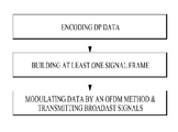
- the present invention provides a method of transmitting broadcast signals.
- the method of transmitting broadcast signals includes encoding Data Pipe, DP, data according to a code rate, wherein the encoding further includes Low-Density Parity-Check, LDPC, encoding the DP data using addresses of a parity check matrix and length of a LDPC codeword, wherein the addresses of the parity check matrix indicates addresses of parity bits to be calculated, wherein the addresses of the parity check matrix is defined according to the code rate, Bit interleaving the LDPC encoded DP data, and mapping the bit interleaved DP data onto constellations;
- LDPC Low-Density Parity-Check
- OFDM Orthogonal Frequency Division Multiplexing
- the code rate is 5/15, wherein the length of the LDPC codeword is 16200 bits.
- the parity check matrix includes an information part corresponding to information bits of the LDPC codeword and a parity part corresponding to the parity bits of the LDPC codeword, wherein the addresses of the parity check matrix is expressed as
- each row represents a first information bit in each group of 360 information bits, wherein each value corresponding to the each row represents the addresses of the parity bits to be calculated.
- each of first to third rows has 30 addresses of the parity bits
- each of fourth to eleventh rows has 4 addresses of the parity bits
- each of twelfth to fifteenth rows has 3 addresses of the parity bits.
- the method further includes: generating a preamble symbol by repeating at least one signaling information, wherein the preamble includes the preamble symbol.
- the method further includes: generating the guard interval using at least one sequence and the preamble symbol; and generating the preamble by combining the guard interval and the preamble symbol.
- the present invention provides a method of receiving broadcast signals.
- the method of receiving broadcast signals includes receiving broadcast signals having modulated data in signal frames and de-modulating the modulated data by an Orthogonal Frequency Division Multiplexing, OFDM, method; parsing at least one signal frame by de-mapping Data Pipe, DP, data; decoding the DP data according to a code rate, wherein the decoding further includes de-mapping the DP data from constellations, Bit de-interleaving the de-mapped DP data, and Low-Density Parity-Check, LDPC, decoding the bit de-interleaved DP data using addresses of a parity check matrix and length of a LDPC codeword, wherein the addresses of the parity check matrix indicates addresses of parity bits to be calculated, wherein the addresses of the parity check matrix is defined according to the code rate;
- OFDM Orthogonal Frequency Division Multiplexing
- the signal frame includes a preamble, wherein the preamble includes guard interval.
- the code rate is 5/15, wherein the length of the LDPC codeword is 16200 bits.
- the parity check matrix includes an information part corresponding to information bits of the LDPC codeword and a parity part corresponding to the parity bits of the LDPC codeword, wherein the addresses of the parity check matrix is expressed as
- each row represents a first information bit in each group of 360 information bits, wherein each value corresponding to the each row represents the addresses of the parity bits to be calculated.
- each of first to third rows has 30 addresses of the parity bits
- each of fourth to eleventh rows has 4 addresses of the parity bits
- each of twelfth to fifteenth rows has 3 addresses of the parity bits.
- the preamble includes a preamble symbol generated by repeating at least one signaling information.
- the guard interval is generated by using at least one sequence and the preamble symbol, and wherein the preamble is generated by combining the guard interval and the preamble symbol.
- the present invention provides an apparatus for transmitting broadcast signals.
- the apparatus for transmitting broadcast signals includes an encoding module configured to encode Data Pipe, DP, data according to a code rate, wherein the encoding module includes a Low-Density Parity-Check, LDPC, encoding module configured to LDPC encode the DP data using addresses of a parity check matrix and length of a LDPC codeword, wherein the addresses of the parity check matrix indicates addresses of parity bits to be calculated, wherein the addresses of the parity check matrix is defined according to the code rate, a Bit interleaving module configured to bit interleave the LDPC encoded DP data, and a mapping module configured to map the bit interleaved DP data onto constellations; a frame building module configured to build at least one signal frame by mapping the encoded DP data; a modulating module configured to modulate data in the built signal frame by an Orthogonal Frequency Division Multiplexing, OFDM, method; and a transmitting module configured to transmit the
- the code rate is 5/15, wherein the length of the LDPC codeword is 16200 bits.
- the parity check matrix includes an information part corresponding to information bits of the LDPC codeword and a parity part corresponding to the parity bits of the LDPC codeword, wherein the addresses of the parity check matrix is expressed as
- each of first to third rows has 30 addresses of the parity bits
- each of fourth to eleventh rows has 4 addresses of the parity bits
- each of twelfth to fifteenth rows has 3 addresses of the parity bits.
- the apparatus further includes: a preamble generating module configured to repeat at least one signaling information to generate a preamble symbol, wherein the preamble includes the preamble symbol.
- a preamble generating module configured to repeat at least one signaling information to generate a preamble symbol, wherein the preamble includes the preamble symbol.
- the preamble generating module further configured to generate the guard interval using at least one sequence and the preamble symbol, and to generate the preamble by combining the guard interval and the preamble symbol.
- the present invention provides an apparatus for receiving broadcast signals.
- the apparatus for receiving broadcast signals includes a receiving module configured to receive broadcast signals having modulated data in signal frames; a de-modulating module configured to de-modulate the modulated data by an Orthogonal Frequency Division Multiplexing, OFDM, method; a parsing module configured to parse at least one signal frame by de-mapping Data Pipe, DP, data; a decoding module configured to decode the DP data according to a code rate, wherein the decoding module includes a de-mapping module configured to de-map the DP data from constellations, a Bit de-interleaving module configured to bit de-interleave the de-mapped DP data, and a Low-Density Parity-Check, LDPC, decoding module configured to LDPC decode the bit de-interleaved DP data using addresses of a parity check matrix and length of a LDPC codeword, wherein the addresses of the parity check matrix indicates addresses of parity bits
- the code rate is 5/15, wherein the length of the LDPC codeword is 16200 bits.
- the parity check matrix includes an information part corresponding to information bits of the LDPC codeword and a parity part corresponding to the parity bits of the LDPC codeword, wherein the addresses of the parity check matrix is expressed as
- each row represents a first information bit in each group of 360 information bits, wherein each value corresponding to the each row represents the addresses of the parity bits to be calculated.
- each of first to third rows has 30 addresses of the parity bits
- each of fourth to eleventh rows has 4 addresses of the parity bits
- each of twelfth to fifteenth rows has 3 addresses of the parity bits.
- the preamble includes a preamble symbol generated by repeating at least one signaling information.
- the guard interval is generated by using at least one sequence and the preamble symbol, and wherein the preamble is generated by combining the guard interval and the preamble symbol.
- the present invention can process data according to service characteristics to control QoS (Quality of Services) for each service or service component, thereby providing various broadcast services.
- QoS Quality of Services
- the present invention can achieve transmission flexibility by transmitting various broadcast services through the same RF signal bandwidth.
- the present invention can improve data transmission efficiency and increase robustness of transmission/reception of broadcast signals using a MIMO system.
- the present invention it is possible to provide broadcast signal transmission and reception methods and apparatus capable of receiving digital broadcast signals without error even with mobile reception equipment or in an indoor environment.
- FIG. 1 illustrates a structure of an apparatus for transmitting broadcast signals for future broadcast services according to an embodiment of the present invention.
- FIG. 2 illustrates an input formatting block according to one embodiment of the present invention.
- FIG. 3 illustrates an input formatting block according to another embodiment of the present invention.
- FIG. 4 illustrates an input formatting block according to another embodiment of the present invention.
- FIG. 5 illustrates a BICM block according to an embodiment of the present invention.
- FIG. 6 illustrates a BICM block according to another embodiment of the present invention.
- FIG. 7 illustrates a frame building block according to one embodiment of the present invention.
- FIG. 8 illustrates an OFMD generation block according to an embodiment of the present invention.
- FIG. 9 illustrates a structure of an apparatus for receiving broadcast signals for future broadcast services according to an embodiment of the present invention.
- FIG. 10 illustrates a frame structure according to an embodiment of the present invention.
- FIG. 11 illustrates a signaling hierarchy structure of the frame according to an embodiment of the present invention.
- FIG. 12 illustrates preamble signaling data according to an embodiment of the present invention.
- FIG. 13 illustrates PLS1 data according to an embodiment of the present invention.
- FIG. 14 illustrates PLS2 data according to an embodiment of the present invention.
- FIG. 15 illustrates PLS2 data according to another embodiment of the present invention.
- FIG. 16 illustrates a logical structure of a frame according to an embodiment of the present invention.
- FIG. 17 illustrates PLS mapping according to an embodiment of the present invention.
- FIG. 18 illustrates EAC mapping according to an embodiment of the present invention.
- FIG. 19 illustrates FIC mapping according to an embodiment of the present invention.
- FIG. 20 illustrates a type of DP according to an embodiment of the present invention.
- FIG. 21 illustrates DP mapping according to an embodiment of the present invention.
- FIG. 22 illustrates an FEC structure according to an embodiment of the present invention.
- FIG. 23 illustrates a bit interleaving according to an embodiment of the present invention.
- FIG. 24 illustrates a cell-word demultiplexing according to an embodiment of the present invention.
- FIG. 25 illustrates a time interleaving according to an embodiment of the present invention.
- FIG. 26 shows a parity check matrix of a QC-IRA (quasi-cyclic irregular repeat accumulate) LDPC code.
- FIG. 27 shows a process of encoding the QC-IRA LDPC code according to an embodiment of the present invention.
- FIG. 28 illustrates a parity check matrix permutation process according to an embodiment of the present invention.
- FIG. 29 is a table showing addresses of parity check matrix according to an embodiment of the present invention.
- FIG. 30 is a table showing addresses of parity check matrix according to another embodiment of the present invention.
- FIG. 31 illustrates a method for sequentially encoding the QC-IRA LDPC code according to an embodiment of the present invention.
- FIG. 32 illustrates an LDPC decoder according to an embodiment of the present invention.
- FIG. 33 illustrates time-domain structure of the normal preamble according to an embodiment of the present invention.
- FIG. 34 illustrates block diagram of the normal preamble symbol insertion according to an embodiment of the present invention.
- FIG. 35 illustrates sub-matrixes of Reed Muller generator matrix G according to an embodiment of the present invention.
- FIG. 36 illustrates a Signaling Scrambler Sequence (SSS) generator according to an embodiment of the present invention.
- SSS Signaling Scrambler Sequence
- FIG. 37 illustrates distribution of the active carriers according to an embodiment of the present invention.
- FIG. 38 illustrates location of the active carriers according to an embodiment of the present invention.
- FIG. 39 illustrates time-domain structure of the robust preamble according to an embodiment of the present invention.
- FIG. 40 illustrates block diagram of the robust preamble symbol insertion according to an embodiment of the present invention.
- FIG. 41 illustrates a method of transmitting broadcast signal according to an embodiment of the present invention.
- FIG. 42 illustrates the basic operation of a twisted row-column block interleaver according to an embodiment of the present invention.
- FIG. 43 illustrates an operation of a twisted row-column block interleaver according to another embodiment of the present invention.
- FIG. 44 illustrates a diagonal-wise reading pattern of a twisted row-column block interleaver according to an embodiment of the present invention.
- FIG. 45 illustrates interleaved XFECBLOCKs from each interleaving array according to an embodiment of the present invention.
- FIG. 46 illustrates one of the embodiments of the H1 matrix according to a code rate of 5/15.
- FIG. 47 illustrates one of the embodiments of the H2 matrix according to a code rate of 5/15.
- FIG. 48 illustrates one of the embodiments of the degree distribution table according to a code rate of 5/15.
- FIG. 49 illustrates one of the embodiments of the H1 matrix according to a code rate of 8/15.
- FIG. 50 illustrates one of the embodiments of the H2 matrix according to a code rate of 8/15.
- FIG. 51 illustrates one of the embodiments of the degree distribution table according to a code rate of 8/15.
- FIG. 52 illustrates one of the embodiments of the H1 matrix according to a code rate of 10/15.
- FIG. 53 illustrates one of the embodiments of the H2 matrix according to a code rate of 10/15.
- FIG. 54 illustrates one of the embodiments of the degree distribution table according to a code rate of 10/15.
- FIG. 55 illustrates one of the embodiments of the H1 matrix according to a code rate of 12/15.
- FIG. 56 illustrates one of the embodiments of the H2 matrix according to a code rate of 12/15.
- FIG. 57 illustrates one of the embodiments of the degree distribution table according to a code rate of 12/15.
- FIG. 58 illustrates one of the embodiments of the H1 matrix according to a code rate of 10/15.
- FIG. 59 illustrates one of the embodiments of the H2 matrix according to a code rate of 10/15.
- FIG. 60 illustrates one of the embodiments of the degree distribution table according to a code rate of 10/15.
- FIG. 61 illustrates one of the embodiments of the H1 matrix according to a code rate of 12/15.
- FIG. 62 illustrates one of the embodiments of the H2 matrix according to a code rate of 12/15.
- FIG. 63 illustrates one of the embodiments of the degree distribution table according to a code rate of 12/15.
- the present invention provides apparatuses and methods for transmitting and receiving broadcast signals for future broadcast services.
- Future broadcast services include a terrestrial broadcast service, a mobile broadcast service, a UHDTV service, etc.
- the present invention may process broadcast signals for the future broadcast services through non-MIMO (Multiple Input Multiple Output) or MIMO according to one embodiment.
- a non-MIMO scheme according to an embodiment of the present invention may include a MISO (Multiple Input Single Output) scheme, a SISO (Single Input Single Output) scheme, etc.
- MISO or MIMO uses two antennas in the following for convenience of description, the present invention is applicable to systems using two or more antennas.
- the present invention may defines three physical layer (PL) profiles (base, handheld and advanced profiles) each optimized to minimize receiver complexity while attaining the performance required for a particular use case.
- the physical layer (PHY) profiles are subsets of all configurations that a corresponding receiver should implement.
- the three PHY profiles share most of the functional blocks but differ slightly in specific blocks and/or parameters. Additional PHY profiles can be defined in the future. For the system evolution, future profiles can also be multiplexed with the existing profiles in a single RF channel through a future extension frame (FEF). The details of each PHY profile are described below.
- FEF future extension frame
- the base profile represents a main use case for fixed receiving devices that are usually connected to a roof-top antenna.
- the base profile also includes portable devices that could be transported to a place but belong to a relatively stationary reception category. Use of the base profile could be extended to handheld devices or even vehicular by some improved implementations, but those use cases are not expected for the base profile receiver operation.
- Target SNR range of reception is from approximately 10 to 20 dB, which includes the 15 dB SNR reception capability of the existing broadcast system (e.g. ATSC A/53).
- the receiver complexity and power consumption is not as critical as in the battery-operated handheld devices, which will use the handheld profile. Key system parameters for the base profile are listed in below table 1.
- the handheld profile is designed for use in handheld and vehicular devices that operate with battery power.
- the devices can be moving with pedestrian or vehicle speed.
- the power consumption as well as the receiver complexity is very important for the implementation of the devices of the handheld profile.
- the target SNR range of the handheld profile is approximately 0 to 10 dB, but can be configured to reach below 0 dB when intended for deeper indoor reception.
- the advanced profile provides highest channel capacity at the cost of more implementation complexity.
- This profile requires using MIMO transmission and reception, and UHDTV service is a target use case for which this profile is specifically designed.
- the increased capacity can also be used to allow an increased number of services in a given bandwidth, e.g., multiple SDTV or HDTV services.
- the target SNR range of the advanced profile is approximately 20 to 30 dB.
- MIMO transmission may initially use existing elliptically-polarized transmission equipment, with extension to full-power cross-polarized transmission in the future.
- Key system parameters for the advanced profile are listed in below table 3.
- the base profile can be used as a profile for both the terrestrial broadcast service and the mobile broadcast service. That is, the base profile can be used to define a concept of a profile which includes the mobile profile. Also, the advanced profile can be divided advanced profile for a base profile with MIMO and advanced profile for a handheld profile with MIMO. Moreover, the three profiles can be changed according to intention of the designer.
- auxiliary stream sequence of cells carrying data of as yet undefined modulation and coding, which may be used for future extensions or as required by broadcasters or network operators
- base data pipe data pipe that carries service signaling data
- baseband frame (or BBFRAME): set of Kbch bits which form the input to one FEC encoding process (BCH and LDPC encoding)
- data pipe logical channel in the physical layer that carries service data or related metadata, which may carry one or multiple service(s) or service component(s).
- data pipe unit a basic unit for allocating data cells to a DP in a frame.
- DP_ID this 8 bit field identifies uniquely a DP within the system identified by the SYSTEM_ID
- dummy cell cell carrying a pseudorandom value used to fill the remaining capacity not used for PLS signaling, DPs or auxiliary streams
- emergency alert channel part of a frame that carries EAS information data
- frame repetition unit a set of frames belonging to same or different physical layer profile including a FEF, which is repeated eight times in a super-frame
- fast information channel a logical channel in a frame that carries the mapping information between a service and the corresponding base DP
- FECBLOCK set of LDPC-encoded bits of a DP data
- FFT size nominal FFT size used for a particular mode, equal to the active symbol period Ts expressed in cycles of the elementary period T
- frame signaling symbol OFDM symbol with higher pilot density used at the start of a frame in certain combinations of FFT size, guard interval and scattered pilot pattern, which carries a part of the PLS data
- frame edge symbol OFDM symbol with higher pilot density used at the end of a frame in certain combinations of FFT size, guard interval and scattered pilot pattern
- frame-group the set of all the frames having the same PHY profile type in a super-frame.
- future extension frame physical layer time slot within the super-frame that could be used for future extension, which starts with a preamble
- Futurecast UTB system proposed physical layer broadcasting system, of which the input is one or more MPEG2-TS or IP or general stream(s) and of which the output is an RF signal
- input stream A stream of data for an ensemble of services delivered to the end users by the system.
- PHY profile subset of all configurations that a corresponding receiver should implement
- PLS physical layer signaling data consisting of PLS1 and PLS2
- PLS1 a first set of PLS data carried in the FSS symbols having a fixed size, coding and modulation, which carries basic information about the system as well as the parameters needed to decode the PLS2
- PLS2 a second set of PLS data transmitted in the FSS symbol, which carries more detailed PLS data about the system and the DPs
- PLS2 dynamic data PLS2 data that may dynamically change frame-by-frame
- PLS2 static data PLS2 data that remains static for the duration of a frame-group
- preamble signaling data signaling data carried by the preamble symbol and used to identify the basic mode of the system
- preamble symbol fixed-length pilot symbol that carries basic PLS data and is located in the beginning of a frame
- the preamble symbol is mainly used for fast initial band scan to detect the system signal, its timing, frequency offset, and FFTsize.
- superframe set of eight frame repetition units
- time interleaving block set of cells within which time interleaving is carried out, corresponding to one use of the time interleaver memory
- TI group unit over which dynamic capacity allocation for a particular DP is carried out, made up of an integer, dynamically varying number of XFECBLOCKs.
- the TI group may be mapped directly to one frame or may be mapped to multiple frames. It may contain one or more TI blocks.
- Type 1 DP DP of a frame where all DPs are mapped into the frame in TDM fashion
- Type 2 DP DP of a frame where all DPs are mapped into the frame in FDM fashion
- XFECBLOCK set of Ncells cells carrying all the bits of one LDPC FECBLOCK
- FIG. 1 illustrates a structure of an apparatus for transmitting broadcast signals for future broadcast services according to an embodiment of the present invention.
- the apparatus for transmitting broadcast signals for future broadcast services can include an input formatting block 1000 , a BICM (Bit interleaved coding & modulation) block 1010 , a frame structure block 1020 , an OFDM (Orthogonal Frequency Division Multiplexing) generation block 1030 and a signaling generation block 1040 .
- BICM Bit interleaved coding & modulation
- OFDM Orthogonal Frequency Division Multiplexing
- IP stream/packets and MPEG2-TS are the main input formats, other stream types are handled as General Streams.
- Management Information is input to control the scheduling and allocation of the corresponding bandwidth for each input stream.
- One or multiple TS stream(s), IP stream(s) and/or General Stream(s) inputs are simultaneously allowed.
- the input formatting block 1000 can demultiplex each input stream into one or multiple data pipe(s), to each of which an independent coding and modulation is applied.
- the data pipe (DP) is the basic unit for robustness control, thereby affecting quality-of-service (QoS).
- QoS quality-of-service
- One or multiple service(s) or service component(s) can be carried by a single DP. Details of operations of the input formatting block 1000 will be described later.
- the data pipe is a logical channel in the physical layer that carries service data or related metadata, which may carry one or multiple service(s) or service component(s).
- the data pipe unit a basic unit for allocating data cells to a DP in a frame.
- parity data is added for error correction and the encoded bit streams are mapped to complex-value constellation symbols.
- the symbols are interleaved across a specific interleaving depth that is used for the corresponding DP.
- MIMO encoding is performed in the BICM block 1010 and the additional data path is added at the output for MIMO transmission. Details of operations of the BICM block 1010 will be described later.
- the Frame Building block 1020 can map the data cells of the input DPs into the OFDM symbols within a frame. After mapping, the frequency interleaving is used for frequency-domain diversity, especially to combat frequency-selective fading channels. Details of operations of the Frame Building block 1020 will be described later.
- the OFDM Generation block 1030 can apply conventional OFDM modulation having a cyclic prefix as guard interval. For antenna space diversity, a distributed MISO scheme is applied across the transmitters. In addition, a Peak-to-Average Power Reduction (PAPR) scheme is performed in the time domain. For flexible network planning, this proposal provides a set of various FFT sizes, guard interval lengths and corresponding pilot patterns. Details of operations of the OFDM Generation block 1030 will be described later.
- PAPR Peak-to-Average Power Reduction
- the Signaling Generation block 1040 can create physical layer signaling information used for the operation of each functional block. This signaling information is also transmitted so that the services of interest are properly recovered at the receiver side. Details of operations of the Signaling Generation block 1040 will be described later.
- FIGS. 2, 3 and 4 illustrate the input formatting block 1000 according to embodiments of the present invention. A description will be given of each figure.
- FIG. 2 illustrates an input formatting block according to one embodiment of the present invention.
- FIG. 2 shows an input formatting module when the input signal is a single input stream.
- the input formatting block illustrated in FIG. 2 corresponds to an embodiment of the input formatting block 1000 described with reference to FIG. 1 .
- the input to the physical layer may be composed of one or multiple data streams. Each data stream is carried by one DP.
- the mode adaptation modules slice the incoming data stream into data fields of the baseband frame (BBF).
- BBF baseband frame
- the system supports three types of input data streams: MPEG2-TS, Internet protocol (IP) and Generic stream (GS).
- MPEG2-TS is characterized by fixed length (188 byte) packets with the first byte being a sync-byte (0x47).
- An IP stream is composed of variable length IP datagram packets, as signaled within IP packet headers.
- the system supports both IPv4 and IPv6 for the IP stream.
- GS may be composed of variable length packets or constant length packets, signaled within encapsulation packet headers.
- the Input Stream Splitter splits the input TS, IP, GS streams into multiple service or service component (audio, video, etc.) streams.
- the mode adaptation module 2010 is comprised of a CRC Encoder, BB (baseband) Frame Slicer, and BB Frame Header Insertion block.
- the CRC Encoder provides three kinds of CRC encoding for error detection at the user packet (UP) level, i.e., CRC-8, CRC-16, and CRC-32.
- the computed CRC bytes are appended after the UP.
- CRC-8 is used for TS stream and CRC-32 for IP stream. If the GS stream doesn't provide the CRC encoding, the proposed CRC encoding should be applied.
- the BB Frame Slicer maps the input into an internal logical-bit format.
- the first received bit is defined to be the MSB.
- the BB Frame Slicer allocates a number of input bits equal to the available data field capacity.
- the UP packet stream is sliced to fit the data field of BBF.
- BB Frame Header Insertion block can insert fixed length BBF header of 2 bytes is inserted in front of the BB Frame.
- the BBF header is composed of STUFFI (1 bit), SYNCD (13 bits), and RFU (2 bits).
- BBF can have an extension field (1 or 3 bytes) at the end of the 2-byte BBF header.
- the stream adaptation 2010 is comprised of stuffing insertion block and BB scrambler.
- the stuffing insertion block can insert stuffing field into a payload of a BB frame. If the input data to the stream adaptation is sufficient to fill a BB-Frame, STUFFI is set to ‘0’ and the BBF has no stuffing field. Otherwise STUFFI is set to ‘1’ and the stuffing field is inserted immediately after the BBF header.
- the stuffing field comprises two bytes of the stuffing field header and a variable size of stuffing data.
- the BB scrambler scrambles complete BBF for energy dispersal.
- the scrambling sequence is synchronous with the BBF.
- the scrambling sequence is generated by the feed-back shift register.
- the PLS generation block 2020 can generate physical layer signaling (PLS) data.
- PLS provides the receiver with a means to access physical layer DPs.
- the PLS data consists of PLS1 data and PLS2 data.
- the PLS1 data is a first set of PLS data carried in the FSS symbols in the frame having a fixed size, coding and modulation, which carries basic information about the system as well as the parameters needed to decode the PLS2 data.
- the PLS1 data provides basic transmission parameters including parameters required to enable the reception and decoding of the PLS2 data. Also, the PLS1 data remains constant for the duration of a frame-group.
- the PLS2 data is a second set of PLS data transmitted in the FSS symbol, which carries more detailed PLS data about the system and the DPs.
- the PLS2 contains parameters that provide sufficient information for the receiver to decode the desired DP.
- the PLS2 signaling further consists of two types of parameters, PLS2 Static data (PLS2-STAT data) and PLS2 dynamic data (PLS2-DYN data).
- PLS2 Static data is PLS2 data that remains static for the duration of a frame-group and the PLS2 dynamic data is PLS2 data that may dynamically change frame-by-frame.
- the PLS scrambler 2030 can scramble the generated PLS data for energy dispersal.
- FIG. 3 illustrates an input formatting block according to another embodiment of the present invention.
- the input formatting block illustrated in FIG. 3 corresponds to an embodiment of the input formatting block 1000 described with reference to FIG. 1 .
- FIG. 3 shows a mode adaptation block of the input formatting block when the input signal corresponds to multiple input streams.
- the mode adaptation block of the input formatting block for processing the multiple input streams can independently process the multiple input streams.
- the mode adaptation block for respectively processing the multiple input streams can include an input stream splitter 3000 , an input stream synchronizer 3010 , a compensating delay block 3020 , a null packet deletion block 3030 , a head compression block 3040 , a CRC encoder 3050 , a BB frame slicer 3060 and a BB header insertion block 3070 . Description will be given of each block of the mode adaptation block.
- Operations of the CRC encoder 3050 , BB frame slicer 3060 and BB header insertion block 3070 correspond to those of the CRC encoder, BB frame slicer and BB header insertion block described with reference to FIG. 2 and thus description thereof is omitted.
- the input stream splitter 3000 can split the input TS, IP, GS streams into multiple service or service component (audio, video, etc.) streams.
- the input stream synchronizer 3010 may be referred as ISSY.
- the ISSY can provide suitable means to guarantee Constant Bit Rate (CBR) and constant end-to-end transmission delay for any input data format.
- CBR Constant Bit Rate
- the ISSY is always used for the case of multiple DPs carrying TS, and optionally used for multiple DPs carrying GS streams.
- the compensating delay block 3020 can delay the split TS packet stream following the insertion of ISSY information to allow a TS packet recombining mechanism without requiring additional memory in the receiver.
- the null packet deletion block 3030 is used only for the TS input stream case. Some TS input streams or split TS streams may have a large number of null-packets present in order to accommodate VBR (variable bit-rate) services in a CBR TS stream. In this case, in order to avoid unnecessary transmission overhead, null-packets can be identified and not transmitted. In the receiver, removed null-packets can be re-inserted in the exact place where they were originally by reference to a deleted null-packet (DNP) counter that is inserted in the transmission, thus guaranteeing constant bit-rate and avoiding the need for time-stamp (PCR) updating.
- DNP deleted null-packet
- the head compression block 3040 can provide packet header compression to increase transmission efficiency for TS or IP input streams. Because the receiver can have a priori information on certain parts of the header, this known information can be deleted in the transmitter.
- the receiver For Transport Stream, the receiver has a-priori information about the sync-byte configuration (0x47) and the packet length (188 Byte). If the input TS stream carries content that has only one PID, i.e., for only one service component (video, audio, etc.) or service sub-component (SVC base layer, SVC enhancement layer, MVC base view or MVC dependent views), TS packet header compression can be applied (optionally) to the Transport Stream. IP packet header compression is used optionally if the input steam is an IP stream.
- FIG. 4 illustrates an input formatting block according to another embodiment of the present invention.
- the input formatting block illustrated in FIG. 4 corresponds to an embodiment of the input formatting block 1000 described with reference to FIG. 1 .
- FIG. 4 illustrates a stream adaptation block of the input formatting module when the input signal corresponds to multiple input streams.
- the mode adaptation block for respectively processing the multiple input streams can include a scheduler 4000 , an 1-Frame delay block 4010 , a stuffing insertion block 4020 , an in-band signaling 4030 , a BB Frame scrambler 4040 , a PLS generation block 4050 and a PLS scrambler 4060 . Description will be given of each block of the stream adaptation block.
- Operations of the stuffing insertion block 4020 , the BB Frame scrambler 4040 , the PLS generation block 4050 and the PLS scrambler 4060 correspond to those of the stuffing insertion block, BB scrambler, PLS generation block and the PLS scrambler described with reference to FIG. 2 and thus description thereof is omitted.
- the scheduler 4000 can determine the overall cell allocation across the entire frame from the amount of FECBLOCKs of each DP. Including the allocation for PLS, EAC and FIC, the scheduler generate the values of PLS2-DYN data, which is transmitted as in-band signaling or PLS cell in FSS of the frame. Details of FECBLOCK, EAC and FIC will be described later.
- the 1-Frame delay block 4010 can delay the input data by one transmission frame such that scheduling information about the next frame can be transmitted through the current frame for in-band signaling information to be inserted into the DPs.
- the in-band signaling 4030 can insert un-delayed part of the PLS2 data into a DP of a frame.
- FIG. 5 illustrates a BICM block according to an embodiment of the present invention.
- the BICM block illustrated in FIG. 5 corresponds to an embodiment of the BICM block 1010 described with reference to FIG. 1 .
- the apparatus for transmitting broadcast signals for future broadcast services can provide a terrestrial broadcast service, mobile broadcast service, UHDTV service, etc.
- the a BICM block according to an embodiment of the present invention can independently process DPs input thereto by independently applying SISO, MISO and MIMO schemes to the data pipes respectively corresponding to data paths. Consequently, the apparatus for transmitting broadcast signals for future broadcast services according to an embodiment of the present invention can control QoS for each service or service component transmitted through each DP.
- the BICM block shared by the base profile and the handheld profile and the BICM block of the advanced profile can include plural processing blocks for processing each DP.
- a processing block 5000 of the BICM block for the base profile and the handheld profile can include a Data FEC encoder 5010 , a bit interleaver 5020 , a constellation mapper 5030 , an SSD (Signal Space Diversity) encoding block 5040 and a time interleaver 5050 .
- a Data FEC encoder 5010 a bit interleaver 5020 , a constellation mapper 5030 , an SSD (Signal Space Diversity) encoding block 5040 and a time interleaver 5050 .
- the Data FEC encoder 5010 can perform the FEC encoding on the input BBF to generate FECBLOCK procedure using outer coding (BCH), and inner coding (LDPC).
- BCH outer coding
- LDPC inner coding
- the outer coding (BCH) is optional coding method. Details of operations of the Data FEC encoder 5010 will be described later.
- the bit interleaver 5020 can interleave outputs of the Data FEC encoder 5010 to achieve optimized performance with combination of the LDPC codes and modulation scheme while providing an efficiently implementable structure. Details of operations of the bit interleaver 5020 will be described later.
- the constellation mapper 5030 can modulate each cell word from the bit interleaver 5020 in the base and the handheld profiles, or cell word from the Cell-word demultiplexer 5010 - 1 in the advanced profile using either QPSK, QAM-16, non-uniform QAM (NUQ-64, NUQ-256, NUQ-1024) or non-uniform constellation (NUC-16, NUC-64, NUC-256, NUC-1024) to give a power-normalized constellation point, e 1 .
- This constellation mapping is applied only for DPs. Observe that QAM-16 and NUQs are square shaped, while NUCs have arbitrary shape. When each constellation is rotated by any multiple of 90 degrees, the rotated constellation exactly overlaps with its original one.
- the SSD encoding block 5040 can precode cells in two (2D), three (3D), and four (4D) dimensions to increase the reception robustness under difficult fading conditions.
- the time interleaver 5050 can operates at the DP level.
- the parameters of time interleaving (TI) may be set differently for each DP. Details of operations of the time interleaver 5050 will be described later.
- a processing block 5000 - 1 of the BICM block for the advanced profile can include the Data FEC encoder, bit interleaver, constellation mapper, and time interleaver. However, the processing block 5000 - 1 is distinguished from the processing block 5000 further includes a cell-word demultiplexer 5010 - 1 and a MIMO encoding block 5020 - 1 .
- the operations of the Data FEC encoder, bit interleaver, constellation mapper, and time interleaver in the processing block 5000 - 1 correspond to those of the Data FEC encoder 5010 , bit interleaver 5020 , constellation mapper 5030 , and time interleaver 5050 described and thus description thereof is omitted.
- the cell-word demultiplexer 5010 - 1 is used for the DP of the advanced profile to divide the single cell-word stream into dual cell-word streams for MIMO processing. Details of operations of the cell-word demultiplexer 5010 - 1 will be described later.
- the MIMO encoding block 5020 - 1 can processing the output of the cell-word demultiplexer 5010 - 1 using MIMO encoding scheme.
- the MIMO encoding scheme was optimized for broadcasting signal transmission.
- the MIMO technology is a promising way to get a capacity increase but it depends on channel characteristics. Especially for broadcasting, the strong LOS component of the channel or a difference in the received signal power between two antennas caused by different signal propagation characteristics makes it difficult to get capacity gain from MIMO.
- the proposed MIMO encoding scheme overcomes this problem using a rotation-based pre-coding and phase randomization of one of the MIMO output signals.
- MIMO encoding is intended for a 2 ⁇ 2 MIMO system requiring at least two antennas at both the transmitter and the receiver.
- Two MIMO encoding modes are defined in this proposal; full-rate spatial multiplexing (FR-SM) and full-rate full-diversity spatial multiplexing (FRFD-SM).
- FR-SM full-rate spatial multiplexing
- FRFD-SM full-rate full-diversity spatial multiplexing
- the FR-SM encoding provides capacity increase with relatively small complexity increase at the receiver side while the FRFD-SM encoding provides capacity increase and additional diversity gain with a great complexity increase at the receiver side.
- the proposed MIMO encoding scheme has no restriction on the antenna polarity configuration.
- MIMO processing is required for the advanced profile frame, which means all DPs in the advanced profile frame are processed by the MIMO encoder. MIMO processing is applied at DP level. Pairs of the Constellation Mapper outputs NUQ (e 1,i and e 2,i ) are fed to the input of the MIMO Encoder. Paired MIMO Encoder output (g1,i and g2,i) is transmitted by the same carrier k and OFDM symbol l of their respective TX antennas.
- FIG. 6 illustrates a BICM block according to another embodiment of the present invention.
- the BICM block illustrated in FIG. 6 corresponds to an embodiment of the BICM block 1010 described with reference to FIG. 1 .
- FIG. 6 illustrates a BICM block for protection of physical layer signaling (PLS), emergency alert channel (EAC) and fast information channel (FIC).
- PLS physical layer signaling
- EAC emergency alert channel
- FIC fast information channel
- the BICM block for protection of PLS, EAC and FIC can include a PLS FEC encoder 6000 , a bit interleaver 6010 , a constellation mapper 6020 and time interleaver 6030 .
- the PLS FEC encoder 6000 can include a scrambler, BCH encoding/zero insertion block, LDPC encoding block and LDPC parity puncturing block. Description will be given of each block of the BICM block.
- the PLS FEC encoder 6000 can encode the scrambled PLS 1/2 data, EAC and FIC section.
- the scrambler can scramble PLS1 data and PLS2 data before BCH encoding and shortened and punctured LDPC encoding.
- the BCH encoding/zero insertion block can perform outer encoding on the scrambled PLS 1/2 data using the shortened BCH code for PLS protection and insert zero bits after the BCH encoding.
- the output bits of the zero insertion may be permuted before LDPC encoding.
- the LDPC encoding block can encode the output of the BCH encoding/zero insertion block using LDPC code.
- the LDPC code parameters for PLS1 and PLS2 are as following table 4.
- the LDPC parity puncturing block can perform puncturing on the PLS1 data and PLS 2 data.
- the bit interleaver 6010 can interleave the each shortened and punctured PLS1 data and PLS2 data.
- Each bit interleaved group is de-multiplexed at bit level in a group before constellation mapping.
- QAM-16 and NUQ-64 when they are mapped to QAM symbol, their bits are cyclic shifted in a group. The cyclic value is increased by 1 at every bit group.
- i is bit group index corresponding to column index in bit interleaving.
- the constellation mapper 6020 can map the bit interleaved PLS1 data and PLS2 data onto constellations.
- the time interleaver 6030 can interleave the mapped PLS1 data and PLS2 data.
- FIG. 7 illustrates a frame building block according to one embodiment of the present invention.
- the frame building block illustrated in FIG. 7 corresponds to an embodiment of the frame building block 1020 described with reference to FIG. 1 .
- the frame building block can include a delay compensation block 7000 , a cell mapper 7010 and a frequency interleaver 7020 . Description will be given of each block of the frame building block.
- the delay compensation block 7000 can adjust the timing between the data pipes and the corresponding PLS data to ensure that they are co-timed at the transmitter end.
- the PLS data is delayed by the same amount as data pipes are by addressing the delays of data pipes caused by the Input Formatting block and BICM block.
- the delay of the BICM block is mainly due to the time interleaver.
- In-band signaling data carries information of the next TI group so that they are carried one frame ahead of the DPs to be signaled.
- the Delay Compensating block delays in-band signaling data accordingly.
- the cell mapper 7010 can map PLS, EAC, FIC, DPs, auxiliary streams and dummy cells into the active carriers of the OFDM symbols in the frame.
- the basic function of the cell mapper 7010 is to map data cells produced by the TIs for each of the DPs, PLS cells, and EAC/FIC cells, if any, into arrays of active OFDM cells corresponding to each of the OFDM symbols within a frame.
- Service signaling data (such as PSI (program specific information)/SI) can be separately gathered and sent by a data pipe.
- PSI program specific information
- SI program specific information
- the frequency interleaver 7020 can randomly interleave data cells received from the cell mapper 7010 to provide frequency diversity. Also, the frequency interleaver 7020 can operate on very OFDM symbol pair comprised of two sequential OFDM symbols using a different interleaving-seed order to get maximum interleaving gain in a single frame. Details of operations of the frequency interleaver 7020 will be described later.
- FIG. 8 illustrates an OFMD generation block according to an embodiment of the present invention.
- the OFMD generation block illustrated in FIG. 8 corresponds to an embodiment of the OFMD generation block 1030 described with reference to FIG. 1 .
- the OFDM generation block modulates the OFDM carriers by the cells produced by the Frame Building block, inserts the pilots, and produces the time domain signal for transmission. Also, this block subsequently inserts guard intervals, and applies PAPR (Peak-to-Average Power Radio) reduction processing to produce the final RF signal.
- PAPR Peak-to-Average Power Radio
- the frame building block can include a pilot and reserved tone insertion block 8000 , a 2D-eSFN encoding block 8010 , an IFFT (Inverse Fast Fourier Transform) block 8020 , a PAPR reduction block 8030 , a guard interval insertion block 8040 , a preamble insertion block 8050 , other system insertion block 8060 and a DAC block 8070 . Description will be given of each block of the frame building block.
- IFFT Inverse Fast Fourier Transform
- the pilot and reserved tone insertion block 8000 can insert pilots and the reserved tone.
- pilots which have transmitted values known a priori in the receiver.
- the information of pilot cells is made up of scattered pilots, continual pilots, edge pilots, FSS (frame signaling symbol) pilots and FES (frame edge symbol) pilots.
- Each pilot is transmitted at a particular boosted power level according to pilot type and pilot pattern.
- the value of the pilot information is derived from a reference sequence, which is a series of values, one for each transmitted carrier on any given symbol.
- the pilots can be used for frame synchronization, frequency synchronization, time synchronization, channel estimation, and transmission mode identification, and also can be used to follow the phase noise.
- Reference information, taken from the reference sequence, is transmitted in scattered pilot cells in every symbol except the preamble, FSS and FES of the frame.
- Continual pilots are inserted in every symbol of the frame. The number and location of continual pilots depends on both the FFT size and the scattered pilot pattern.
- the edge carriers are edge pilots in every symbol except for the preamble symbol. They are inserted in order to allow frequency interpolation up to the edge of the spectrum.
- FSS pilots are inserted in FSS(s) and FES pilots are inserted in FES. They are inserted in order to allow time interpolation up to the edge of the frame.
- the system according to an embodiment of the present invention supports the SFN network, where distributed MISO scheme is optionally used to support very robust transmission mode.
- the 2D-eSFN is a distributed MISO scheme that uses multiple TX antennas, each of which is located in the different transmitter site in the SFN network.
- the 2D-eSFN encoding block 8010 can process a 2D-eSFN processing to distorts the phase of the signals transmitted from multiple transmitters, in order to create both time and frequency diversity in the SFN configuration. Hence, burst errors due to low flat fading or deep-fading for a long time can be mitigated.
- the IFFT block 8020 can modulate the output from the 2D-eSFN encoding block 8010 using OFDM modulation scheme. Any cell in the data symbols which has not been designated as a pilot (or as a reserved tone) carries one of the data cells from the frequency interleaver. The cells are mapped to OFDM carriers.
- the PAPR reduction block 8030 can perform a PAPR reduction on input signal using various PAPR reduction algorithm in the time domain.
- the guard interval insertion block 8040 can insert guard intervals and the preamble insertion block 8050 can insert preamble in front of the signal. Details of a structure of the preamble will be described later.
- the other system insertion block 8060 can multiplex signals of a plurality of broadcast transmission/reception systems in the time domain such that data of two or more different broadcast transmission/reception systems providing broadcast services can be simultaneously transmitted in the same RF signal bandwidth.
- the two or more different broadcast transmission/reception systems refer to systems providing different broadcast services.
- the different broadcast services may refer to a terrestrial broadcast service, mobile broadcast service, etc. Data related to respective broadcast services can be transmitted through different frames.
- the DAC block 8070 can convert an input digital signal into an analog signal and output the analog signal.
- the signal output from the DAC block 7800 can be transmitted through multiple output antennas according to the physical layer profiles.
- a Tx antenna according to an embodiment of the present invention can have vertical or horizontal polarity.
- FIG. 9 illustrates a structure of an apparatus for receiving broadcast signals for future broadcast services according to an embodiment of the present invention.
- the apparatus for receiving broadcast signals for future broadcast services can correspond to the apparatus for transmitting broadcast signals for future broadcast services, described with reference to FIG. 1 .
- the apparatus for receiving broadcast signals for future broadcast services can include a synchronization & demodulation module 9000 , a frame parsing module 9010 , a demapping & decoding module 9020 , an output processor 9030 and a signaling decoding module 9040 .
- a description will be given of operation of each module of the apparatus for receiving broadcast signals.
- the synchronization & demodulation module 9000 can receive input signals through m Rx antennas, perform signal detection and synchronization with respect to a system corresponding to the apparatus for receiving broadcast signals and carry out demodulation corresponding to a reverse procedure of the procedure performed by the apparatus for transmitting broadcast signals.
- the frame parsing module 9100 can parse input signal frames and extract data through which a service selected by a user is transmitted. If the apparatus for transmitting broadcast signals performs interleaving, the frame parsing module 9100 can carry out deinterleaving corresponding to a reverse procedure of interleaving. In this case, the positions of a signal and data that need to be extracted can be obtained by decoding data output from the signaling decoding module 9400 to restore scheduling information generated by the apparatus for transmitting broadcast signals.
- the demapping & decoding module 9200 can convert the input signals into bit domain data and then deinterleave the same as necessary.
- the demapping & decoding module 9200 can perform demapping for mapping applied for transmission efficiency and correct an error generated on a transmission channel through decoding. In this case, the demapping & decoding module 9200 can obtain transmission parameters necessary for demapping and decoding by decoding the data output from the signaling decoding module 9400 .
- the output processor 9300 can perform reverse procedures of various compression/signal processing procedures which are applied by the apparatus for transmitting broadcast signals to improve transmission efficiency.
- the output processor 9300 can acquire necessary control information from data output from the signaling decoding module 9400 .
- the output of the output processor 8300 corresponds to a signal input to the apparatus for transmitting broadcast signals and may be MPEG-TSs, IP streams (v4 or v6) and generic streams.
- the signaling decoding module 9400 can obtain PLS information from the signal demodulated by the synchronization & demodulation module 9000 .
- the frame parsing module 9100 , demapping & decoding module 9200 and output processor 9300 can execute functions thereof using the data output from the signaling decoding module 9400 .
- FIG. 10 illustrates a frame structure according to an embodiment of the present invention.
- FIG. 10 shows an example configuration of the frame types and FRUs in a super-frame.
- (a) shows a super frame according to an embodiment of the present invention
- (b) shows FRU (Frame Repetition Unit) according to an embodiment of the present invention
- (c) shows frames of variable PHY profiles in the FRU
- (d) shows a structure of a frame.
- a super-frame may be composed of eight FRUs.
- the FRU is a basic multiplexing unit for TDM of the frames, and is repeated eight times in a super-frame.
- Each frame in the FRU belongs to one of the PHY profiles, (base, handheld, advanced) or FEF.
- the maximum allowed number of the frames in the FRU is four and a given PHY profile can appear any number of times from zero times to four times in the FRU (e.g., base, base, handheld, advanced).
- PHY profile definitions can be extended using reserved values of the PHY_PROFILE in the preamble, if required.
- the FEF part is inserted at the end of the FRU, if included.
- the minimum number of FEFs is 8 in a super-frame. It is not recommended that FEF parts be adjacent to each other.
- One frame is further divided into a number of OFDM symbols and a preamble. As shown in (d), the frame comprises a preamble, one or more frame signaling symbols (FSS), normal data symbols and a frame edge symbol (FES).
- FSS frame signaling symbols
- FES normal data symbols
- FES frame edge symbol
- the preamble is a special symbol that enables fast Futurecast UTB system signal detection and provides a set of basic transmission parameters for efficient transmission and reception of the signal. The detailed description of the preamble will be will be described later.
- the main purpose of the FSS(s) is to carry the PLS data.
- the FSS For fast synchronization and channel estimation, and hence fast decoding of PLS data, the FSS has more dense pilot pattern than the normal data symbol.
- the FES has exactly the same pilots as the FSS, which enables frequency-only interpolation within the FES and temporal interpolation, without extrapolation, for symbols immediately preceding the FES.
- FIG. 11 illustrates a signaling hierarchy structure of the frame according to an embodiment of the present invention.
- FIG. 11 illustrates the signaling hierarchy structure, which is split into three main parts: the preamble signaling data 11000 , the PLS1 data 11010 and the PLS2 data 11020 .
- the purpose of the preamble which is carried by the preamble symbol in every frame, is to indicate the transmission type and basic transmission parameters of that frame.
- the PLS1 enables the receiver to access and decode the PLS2 data, which contains the parameters to access the DP of interest.
- the PLS2 is carried in every frame and split into two main parts: PLS2-STAT data and PLS2-DYN data. The static and dynamic portion of PLS2 data is followed by padding, if necessary.
- FIG. 12 illustrates preamble signaling data according to an embodiment of the present invention.
- Preamble signaling data carries 21 bits of information that are needed to enable the receiver to access PLS data and trace DPs within the frame structure. Details of the preamble signaling data are as follows:
- PHY_PROFILE This 3-bit field indicates the PHY profile type of the current frame. The mapping of different PHY profile types is given in below table 5.
- FFT_SIZE This 2 bit field indicates the FFT size of the current frame within a frame-group, as described in below table 6.
- GI_FRACTION This 3 bit field indicates the guard interval fraction value in the current super-frame, as described in below table 7.
- EAC_FLAG This 1 bit field indicates whether the EAC is provided in the current frame. If this field is set to ‘1’, emergency alert service (EAS) is provided in the current frame. If this field set to ‘0’, EAS is not carried in the current frame. This field can be switched dynamically within a super-frame.
- EAS emergency alert service
- PILOT_MODE This 1-bit field indicates whether the pilot mode is mobile mode or fixed mode for the current frame in the current frame-group. If this field is set to ‘0’, mobile pilot mode is used. If the field is set to ‘1’, the fixed pilot mode is used.
- PAPR_FLAG This 1-bit field indicates whether PAPR reduction is used for the current frame in the current frame-group. If this field is set to value ‘1’, tone reservation is used for PAPR reduction. If this field is set to ‘0’, PAPR reduction is not used.
- FRU_CONFIGURE This 3-bit field indicates the PHY profile type configurations of the frame repetition units (FRU) that are present in the current super-frame. All profile types conveyed in the current super-frame are identified in this field in all preambles in the current super-frame.
- the 3-bit field has a different definition for each profile, as show in below table 8.
- FIG. 13 illustrates PLS1 data according to an embodiment of the present invention.
- PLS1 data provides basic transmission parameters including parameters required to enable the reception and decoding of the PLS2. As above mentioned, the PLS1 data remain unchanged for the entire duration of one frame-group.
- the detailed definition of the signaling fields of the PLS1 data are as follows:
- PREAMBLE_DATA This 20-bit field is a copy of the preamble signaling data excluding the EAC_FLAG.
- NUM_FRAME_FRU This 2-bit field indicates the number of the frames per FRU.
- PAYLOAD_TYPE This 3-bit field indicates the format of the payload data carried in the frame-group. PAYLOAD_TYPE is signaled as shown in table 9.
- Payload type 1XX TS stream is transmitted X1X IP stream is transmitted XX1 GS stream is transmitted
- NUM_FSS This 2-bit field indicates the number of FSS symbols in the current frame.
- SYSTEM_VERSION This 8-bit field indicates the version of the transmitted signal format.
- the SYSTEM_VERSION is divided into two 4-bit fields, which are a major version and a minor version.
- MSB four bits of SYSTEM_VERSION field indicate major version information.
- a change in the major version field indicates a non-backward-compatible change.
- the default value is ‘0000’.
- the value is set to ‘0000’.
- Minor version The LSB four bits of SYSTEM_VERSION field indicate minor version information. A change in the minor version field is backward-compatible.
- CELL_ID This is a 16-bit field which uniquely identifies a geographic cell in an ATSC network.
- An ATSC cell coverage area may consist of one or more frequencies, depending on the number of frequencies used per Futurecast UTB system. If the value of the CELL_ID is not known or unspecified, this field is set to ‘0’.
- SYSTEM_ID This 16-bit field uniquely identifies the Futurecast UTB system within the ATSC network.
- the Futurecast UTB system is the terrestrial broadcast system whose input is one or more input streams (TS, IP, GS) and whose output is an RF signal.
- the Futurecast UTB system carries one or more PHY profiles and FEF, if any.
- the same Futurecast UTB system may carry different input streams and use different RF frequencies in different geographical areas, allowing local service insertion.
- the frame structure and scheduling is controlled in one place and is identical for all transmissions within a Futurecast UTB system.
- One or more Futurecast UTB systems may have the same SYSTEM_ID meaning that they all have the same physical layer structure and configuration.
- the following loop consists of FRU_PHY_PROFILE, FRU_FRAME_LENGTH, FRU_GI_FRACTION, and RESERVED which are used to indicate the FRU configuration and the length of each frame type.
- the loop size is fixed so that four PHY profiles (including a FEF) are signaled within the FRU. If NUM_FRAME_FRU is less than 4, the unused fields are filled with zeros.
- FRU_PHY_PROFILE This 3-bit field indicates the PHY profile type of the (i+1) th (i is the loop index) frame of the associated FRU. This field uses the same signaling format as shown in the table 8.
- FRU_FRAME_LENGTH This 2-bit field indicates the length of the (i+1) th frame of the associated FRU. Using FRU_FRAME_LENGTH together with FRU_GI_FRACTION, the exact value of the frame duration can be obtained.
- FRU_GI_FRACTION This 3-bit field indicates the guard interval fraction value of the (i+1) th frame of the associated FRU.
- FRU_GI_FRACTION is signaled according to the table 7.
- the following fields provide parameters for decoding the PLS2 data.
- PLS2_FEC_TYPE This 2-bit field indicates the FEC type used by the PLS2 protection.
- the FEC type is signaled according to table 10. The details of the LDPC codes will be described later.
- PLS2_MOD This 3-bit field indicates the modulation type used by the PLS2. The modulation type is signaled according to table 11.
- PLS2_SIZE_CELL This 15-bit field indicates C total _ partial _ block , the size (specified as the number of QAM cells) of the collection of full coded blocks for PLS2 that is carried in the current frame-group. This value is constant during the entire duration of the current frame-group.
- PLS2_STAT_SIZE_BIT This 14-bit field indicates the size, in bits, of the PLS2-STAT for the current frame-group. This value is constant during the entire duration of the current frame-group.
- PLS2_DYN_SIZE_BIT This 14-bit field indicates the size, in bits, of the PLS2-DYN for the current frame-group. This value is constant during the entire duration of the current frame-group.
- PLS2_REP_FLAG This 1-bit flag indicates whether the PLS2 repetition mode is used in the current frame-group. When this field is set to value ‘1’, the PLS2 repetition mode is activated. When this field is set to value ‘0’, the PLS2 repetition mode is deactivated.
- PLS2_REP_SIZE_CELL This 15-bit field indicates C total _ partial _ block , the size (specified as the number of QAM cells) of the collection of partial coded blocks for PLS2 carried in every frame of the current frame-group, when PLS2 repetition is used. If repetition is not used, the value of this field is equal to 0. This value is constant during the entire duration of the current frame-group.
- PLS2_NEXT_FEC_TYPE This 2-bit field indicates the FEC type used for PLS2 that is carried in every frame of the next frame-group. The FEC type is signaled according to the table 10.
- PLS2_NEXT_MOD This 3-bit field indicates the modulation type used for PLS2 that is carried in every frame of the next frame-group. The modulation type is signaled according to the table 11.
- PLS2_NEXT_REP_FLAG This 1-bit flag indicates whether the PLS2 repetition mode is used in the next frame-group. When this field is set to value ‘1’, the PLS2 repetition mode is activated. When this field is set to value ‘0’, the PLS2 repetition mode is deactivated.
- PLS2_NEXT_REP_SIZE_CELL This 15-bit field indicates C total _ full _ block , The size (specified as the number of QAM cells) of the collection of full coded blocks for PLS2 that is carried in every frame of the next frame-group, when PLS2 repetition is used. If repetition is not used in the next frame-group, the value of this field is equal to 0. This value is constant during the entire duration of the current frame-group.
- PLS2_NEXT_REP_STAT_SIZE_BIT This 14-bit field indicates the size, in bits, of the PLS2-STAT for the next frame-group. This value is constant in the current frame-group.
- PLS2_NEXT_REP_DYN_SIZE_BIT This 14-bit field indicates the size, in bits, of the PLS2-DYN for the next frame-group. This value is constant in the current frame-group.
- PLS2_AP_MODE This 2-bit field indicates whether additional parity is provided for PLS2 in the current frame-group. This value is constant during the entire duration of the current frame-group. The below table 12 gives the values of this field. When this field is set to ‘00’, additional parity is not used for the PLS2 in the current frame-group.
- PLS2_AP_SIZE_CELL This 15-bit field indicates the size (specified as the number of QAM cells) of the additional parity bits of the PLS2. This value is constant during the entire duration of the current frame-group.
- PLS2_NEXT_AP_MODE This 2-bit field indicates whether additional parity is provided for PLS2 signaling in every frame of next frame-group. This value is constant during the entire duration of the current frame-group.
- the table 12 defines the values of this field
- PLS2_NEXT_AP_SIZE_CELL This 15-bit field indicates the size (specified as the number of QAM cells) of the additional parity bits of the PLS2 in every frame of the next frame-group. This value is constant during the entire duration of the current frame-group.
- RESERVED This 32-bit field is reserved for future use.
- CRC_32 A 32-bit error detection code, which is applied to the entire PLS1 signaling.
- FIG. 14 illustrates PLS2 data according to an embodiment of the present invention.
- FIG. 14 illustrates PLS2-STAT data of the PLS2 data.
- the PLS2-STAT data are the same within a frame-group, while the PLS2-DYN data provide information that is specific for the current frame.
- FIC_FLAG This 1-bit field indicates whether the FIC is used in the current frame-group. If this field is set to ‘1’, the FIC is provided in the current frame. If this field set to ‘0’, the FIC is not carried in the current frame. This value is constant during the entire duration of the current frame-group.
- AUX_FLAG This 1-bit field indicates whether the auxiliary stream(s) is used in the current frame-group. If this field is set to ‘1’, the auxiliary stream is provided in the current frame. If this field set to ‘0’, the auxiliary stream is not carried in the current frame. This value is constant during the entire duration of current frame-group.
- NUM_DP This 6-bit field indicates the number of DPs carried within the current frame. The value of this field ranges from 1 to 64, and the number of DPs is NUM_DP+1.
- DP_ID This 6-bit field identifies uniquely a DP within a PHY profile.
- DP_TYPE This 3-bit field indicates the type of the DP. This is signaled according to the below table 13.
- DP_GROUP_ID This 8-bit field identifies the DP group with which the current DP is associated. This can be used by a receiver to access the DPs of the service components associated with a particular service, which will have the same DP_GROUP_ID.
- BASE_DP_ID This 6-bit field indicates the DP carrying service signaling data (such as PSI/SI) used in the Management layer.
- the DP indicated by BASE_DP_ID may be either a normal DP carrying the service signaling data along with the service data or a dedicated DP carrying only the service signaling data
- DP_FEC_TYPE This 2-bit field indicates the FEC type used by the associated DP.
- the FEC type is signaled according to the below table 14.
- DP_COD This 4-bit field indicates the code rate used by the associated DP.
- the code rate is signaled according to the below table 15.
- DP_MOD This 4-bit field indicates the modulation used by the associated DP. The modulation is signaled according to the below table 16.
- DP_SSD_FLAG This 1-bit field indicates whether the SSD mode is used in the associated DP. If this field is set to value ‘1’, SSD is used. If this field is set to value ‘0’, SSD is not used.
- PHY_PROFILE is equal to ‘010’, which indicates the advanced profile:
- DP_MIMO This 3-bit field indicates which type of MIMO encoding process is applied to the associated DP. The type of MIMO encoding process is signaled according to the table 17.
- DP_TI_TYPE This 1-bit field indicates the type of time-interleaving. A value of ‘0’ indicates that one TI group corresponds to one frame and contains one or more TI-blocks. A value of ‘1’ indicates that one TI group is carried in more than one frame and contains only one TI-block.
- DP_TI_LENGTH The use of this 2-bit field (the allowed values are only 1, 2, 4, 8) is determined by the values set within the DP_TI_TYPE field as follows:
- the allowed P 1 values with 2-bit field are defined in the below table 18.
- the allowed P 1 values with 2-bit field are defined in the below table 18.
- DP_FRAME_INTERVAL This 2-bit field indicates the frame interval (I JUMP ) within the frame-group for the associated DP and the allowed values are 1, 2, 4, 8 (the corresponding 2-bit field is ‘00’, ‘01’, ‘10’, or ‘11’, respectively). For DPs that do not appear every frame of the frame-group, the value of this field is equal to the interval between successive frames. For example, if a DP appears on the frames 1, 5, 9, 13, etc., this field is set to ‘4’. For DPs that appear in every frame, this field is set to ‘1’.
- DP_TI_BYPASS This 1-bit field determines the availability of time interleaver. If time interleaving is not used for a DP, it is set to ‘1’. Whereas if time interleaving is used it is set to ‘0’.
- DP_FIRST_FRAME_IDX This 5-bit field indicates the index of the first frame of the super-frame in which the current DP occurs.
- the value of DP_FIRST_FRAME_IDX ranges from 0 to 31
- DP_NUM_BLOCK_MAX This 10-bit field indicates the maximum value of DP_NUM_BLOCKS for this DP. The value of this field has the same range as DP_NUM_BLOCKS.
- DP_PAYLOAD_TYPE This 2-bit field indicates the type of the payload data carried by the given DP.
- DP_PAYLOAD_TYPE is signaled according to the below table 19.
- DP_INBAND_MODE This 2-bit field indicates whether the current DP carries in-band signaling information.
- the in-band signaling type is signaled according to the below table 20.
- INBAND-PLS In-band signaling is not carried. 01 INBAND-PLS is carried only 10 INBAND-ISSY is carried only 11 INBAND-PLS and INBAND-ISSY are carried
- DP_PROTOCOL_TYPE This 2-bit field indicates the protocol type of the payload carried by the given DP. It is signaled according to the below table 21 when input payload types are selected.
- DP_CRC_MODE This 2-bit field indicates whether CRC encoding is used in the Input Formatting block.
- the CRC mode is signaled according to the below table 22.
- DNP_MODE This 2-bit field indicates the null-packet deletion mode used by the associated DP when DP_PAYLOAD_TYPE is set to TS (‘00’). DNP_MODE is signaled according to the below table 23. If DP_PAYLOAD_TYPE is not TS (‘00’), DNP_MODE is set to the value ‘00’.
- ISSY_MODE This 2-bit field indicates the ISSY mode used by the associated DP when DP_PAYLOAD_TYPE is set to TS (‘00’).
- the ISSY_MODE is signaled according to the below table 24 If DP_PAYLOAD_TYPE is not TS (‘00’), ISSY_MODE is set to the value ‘00’.
- HC_MODE_TS This 2-bit field indicates the TS header compression mode used by the associated DP when DP_PAYLOAD_TYPE is set to TS (‘00’).
- the HC_MODE_TS is signaled according to the below table 25.
- HC_MODE_IP This 2-bit field indicates the IP header compression mode when DP_PAYLOAD_TYPE is set to IP (‘01’).
- the HC_MODE_IP is signaled according to the below table 26.
- PID This 13-bit field indicates the PID number for TS header compression when DP_PAYLOAD_TYPE is set to TS (‘00’) and HC_MODE_TS is set to ‘01’ or ‘10’.
- FIC_VERSION This 8-bit field indicates the version number of the FIC.
- FIC_LENGTH_BYTE This 13-bit field indicates the length, in bytes, of the FIC.
- NUM_AUX This 4-bit field indicates the number of auxiliary streams. Zero means no auxiliary streams are used.
- AUX_CONFIG_RFU This 8-bit field is reserved for future use.
- AUX_STREAM_TYPE This 4-bit is reserved for future use for indicating the type of the current auxiliary stream.
- AUX_PRIVATE_CONFIG This 28-bit field is reserved for future use for signaling auxiliary streams.
- FIG. 15 illustrates PLS2 data according to another embodiment of the present invention.
- FIG. 15 illustrates PLS2-DYN data of the PLS2 data.
- the values of the PLS2-DYN data may change during the duration of one frame-group, while the size of fields remains constant.
- FRAME_INDEX This 5-bit field indicates the frame index of the current frame within the super-frame.
- the index of the first frame of the super-frame is set to ‘0’.
- PLS_CHANGE_COUNTER This 4-bit field indicates the number of super-frames ahead where the configuration will change. The next super-frame with changes in the configuration is indicated by the value signaled within this field. If this field is set to the value ‘0000’, it means that no scheduled change is foreseen: e.g., value ‘1’ indicates that there is a change in the next super-frame.
- FIC_CHANGE_COUNTER This 4-bit field indicates the number of super-frames ahead where the configuration (i.e., the contents of the FIC) will change. The next super-frame with changes in the configuration is indicated by the value signaled within this field. If this field is set to the value ‘0000’, it means that no scheduled change is foreseen: e.g. value ‘0001’ indicates that there is a change in the next super-frame.
- NUM_DP The following fields appear in the loop over NUM_DP, which describe the parameters associated with the DP carried in the current frame.
- DP_ID This 6-bit field indicates uniquely the DP within a PHY profile.
- DP_START This 15-bit (or 13-bit) field indicates the start position of the first of the DPs using the DPU addressing scheme.
- the DP_START field has differing length according to the PHY profile and FFT size as shown in the below table 27.
- DP_NUM_BLOCK This 10-bit field indicates the number of FEC blocks in the current TI group for the current DP.
- the value of DP_NUM_BLOCK ranges from 0 to 1023
- the following fields indicate the FIC parameters associated with the EAC.
- EAC_FLAG This 1-bit field indicates the existence of the EAC in the current frame. This bit is the same value as the EAC_FLAG in the preamble.
- EAS_WAKE_UP_VERSION_NUM This 8-bit field indicates the version number of a wake-up indication.
- EAC_FLAG field If the EAC_FLAG field is equal to ‘1’, the following 12 bits are allocated for EAC_LENGTH_BYTE field. If the EAC_FLAG field is equal to ‘0’, the following 12 bits are allocated for EAC_COUNTER.
- EAC_LENGTH_BYTE This 12-bit field indicates the length, in byte, of the EAC.
- EAC_COUNTER This 12-bit field indicates the number of the frames before the frame where the EAC arrives.
- AUX_PRIVATE_DYN This 48-bit field is reserved for future use for signaling auxiliary streams. The meaning of this field depends on the value of AUX_STREAM_TYPE in the configurable PLS2-STAT.
- CRC_32 A 32-bit error detection code, which is applied to the entire PLS2.
- FIG. 16 illustrates a logical structure of a frame according to an embodiment of the present invention.
- the PLS, EAC, FIC, DPs, auxiliary streams and dummy cells are mapped into the active carriers of the OFDM symbols in the frame.
- the PLS1 and PLS2 are first mapped into one or more FSS(s). After that, EAC cells, if any, are mapped immediately following the PLS field, followed next by FIC cells, if any.
- the DPs are mapped next after the PLS or EAC, FIC, if any. Type 1 DPs follows first, and Type 2 DPs next. The details of a type of the DP will be described later. In some case, DPs may carry some special data for EAS or service signaling data.
- auxiliary stream or streams follow the DPs, which in turn are followed by dummy cells. Mapping them all together in the above mentioned order, i.e. PLS, EAC, FIC, DPs, auxiliary streams and dummy data cells exactly fill the cell capacity in the frame.
- FIG. 17 illustrates PLS mapping according to an embodiment of the present invention.
- PLS cells are mapped to the active carriers of FSS(s). Depending on the number of cells occupied by PLS, one or more symbols are designated as FSS(s), and the number of FSS(s) N FSS is signaled by NUM_FSS in PLS1.
- the FSS is a special symbol for carrying PLS cells. Since robustness and latency are critical issues in the PLS, the FSS(s) has higher density of pilots allowing fast synchronization and frequency-only interpolation within the FSS.
- PLS cells are mapped to active carriers of the N FSS FSS(s) in a top-down manner as shown in an example in FIG. 17 .
- the PLS1 cells are mapped first from the first cell of the first FSS in an increasing order of the cell index.
- the PLS2 cells follow immediately after the last cell of the PLS1 and mapping continues downward until the last cell index of the first FSS. If the total number of required PLS cells exceeds the number of active carriers of one FSS, mapping proceeds to the next FSS and continues in exactly the same manner as the first FSS.
- DPs are carried next. If EAC, FIC or both are present in the current frame, they are placed between PLS and “normal” DPs.
- FIG. 18 illustrates EAC mapping according to an embodiment of the present invention.
- EAC is a dedicated channel for carrying EAS messages and links to the DPs for EAS. EAS support is provided but EAC itself may or may not be present in every frame. EAC, if any, is mapped immediately after the PLS2 cells. EAC is not preceded by any of the FIC, DPs, auxiliary streams or dummy cells other than the PLS cells. The procedure of mapping the EAC cells is exactly the same as that of the PLS.
- EAC cells are mapped from the next cell of the PLS2 in increasing order of the cell index as shown in the example in FIG. 18 .
- EAC cells may occupy a few symbols, as shown in FIG. 18 .
- EAC cells follow immediately after the last cell of the PLS2, and mapping continues downward until the last cell index of the last FSS. If the total number of required EAC cells exceeds the number of remaining active carriers of the last FSS mapping proceeds to the next symbol and continues in exactly the same manner as FSS(s).
- the next symbol for mapping in this case is the normal data symbol, which has more active carriers than a FSS.
- FIC is carried next, if any exists. If FIC is not transmitted (as signaled in the PLS2 field), DPs follow immediately after the last cell of the EAC.
- FIG. 19 illustrates FIC mapping according to an embodiment of the present invention.
- FIC is a dedicated channel for carrying cross-layer information to enable fast service acquisition and channel scanning. This information primarily includes channel binding information between DPs and the services of each broadcaster. For fast scan, a receiver can decode FIC and obtain information such as broadcaster ID, number of services, and BASE_DP_ID. For fast service acquisition, in addition to FIC, base DP can be decoded using BASE_DP_ID. Other than the content it carries, a base DP is encoded and mapped to a frame in exactly the same way as a normal DP. Therefore, no additional description is required for a base DP.
- the FIC data is generated and consumed in the Management Layer. The content of FIC data is as described in the Management Layer specification.
- the FIC data is optional and the use of FIC is signaled by the FIC_FLAG parameter in the static part of the PLS2. If FIC is used, FIC_FLAG is set to ‘1’ and the signaling field for FIC is defined in the static part of PLS2. Signaled in this field are FIC_VERSION, and FIC_LENGTH_BYTE. FIC uses the same modulation, coding and time interleaving parameters as PLS2. FIC shares the same signaling parameters such as PLS2_MOD and PLS2_FEC. FIC data, if any, is mapped immediately after PLS2 or EAC if any. FIC is not preceded by any normal DPs, auxiliary streams or dummy cells. The method of mapping FIC cells is exactly the same as that of EAC which is again the same as PLS.
- FIC cells are mapped from the next cell of the PLS2 in an increasing order of the cell index as shown in an example in (a).
- FIC cells may be mapped over a few symbols, as shown in (b).
- mapping proceeds to the next symbol and continues in exactly the same manner as FSS(s).
- the next symbol for mapping in this case is the normal data symbol which has more active carriers than a FSS.
- EAC precedes FIC, and FIC cells are mapped from the next cell of the EAC in an increasing order of the cell index as shown in (b).
- one or more DPs are mapped, followed by auxiliary streams, if any, and dummy cells.
- FIG. 20 illustrates a type of DP according to an embodiment of the present invention.
- a DP is categorized into one of two types according to mapping method:
- Type 1 DP DP is mapped by TDM
- Type 2 DP DP is mapped by FDM
- FIG. 20 illustrates the mapping orders of Type 1 DPs and Type 2 DPs.
- Type 2 DPs are first mapped in the increasing order of symbol index, and then after reaching the last OFDM symbol of the frame, the cell index increases by one and the symbol index rolls back to the first available symbol and then increases from that symbol index. After mapping a number of DPs together in one frame, each of the Type 2 DPs are grouped in frequency together, similar to FDM multiplexing of DPs.
- Type 1 DPs and Type 2 DPs can coexist in a frame if needed with one restriction; Type 1 DPs always precede Type 2 DPs.
- the total number of OFDM cells carrying Type 1 and Type 2 DPs cannot exceed the total number of OFDM cells available for transmission of DPs: Math Figure 2 D DP1 +D DP2 ⁇ D DP [Math.2]
- DDP1 is the number of OFDM cells occupied by Type 1 DPs
- DDP2 is the number of cells occupied by Type 2 DPs. Since PLS, EAC, FIC are all mapped in the same way as Type 1 DP, they all follow “Type 1 mapping rule”. Hence, overall, Type 1 mapping always precedes Type 2 mapping.
- FIG. 21 illustrates DP mapping according to an embodiment of the present invention.
- Addressing of OFDM cells for mapping Type 1 DPs (0, . . . , DDP11) is defined for the active data cells of Type 1 DPs.
- the addressing scheme defines the order in which the cells from the TIs for each of the Type 1 DPs are allocated to the active data cells. It is also used to signal the locations of the DPs in the dynamic part of the PLS2.
- address 0 refers to the cell immediately following the last cell carrying PLS in the last FSS. If EAC is transmitted and FIC is not in the corresponding frame, address 0 refers to the cell immediately following the last cell carrying EAC. If FIC is transmitted in the corresponding frame, address 0 refers to the cell immediately following the last cell carrying FIC. Address 0 for Type 1 DPs can be calculated considering two different cases as shown in (a). In the example in (a), PLS, EAC and FIC are assumed to be all transmitted. Extension to the cases where either or both of EAC and FIC are omitted is straightforward. If there are remaining cells in the FSS after mapping all the cells up to FIC as shown on the left side of (a).
- Addressing of OFDM cells for mapping Type 2 DPs (0, . . . , DDP21) is defined for the active data cells of Type 2 DPs.
- the addressing scheme defines the order in which the cells from the TIs for each of the Type 2 DPs are allocated to the active data cells. It is also used to signal the locations of the DPs in the dynamic part of the PLS2.
- Type 1 DP(s) precede Type 2 DP(s) is straightforward since PLS, EAC and FIC follow the same “Type 1 mapping rule” as the Type 1 DP(s).
- a data pipe unit is a basic unit for allocating data cells to a DP in a frame.
- a DPU is defined as a signaling unit for locating DPs in a frame.
- a Cell Mapper 7010 may map the cells produced by the TIs for each of the DPs.
- a Time interleaver 5050 outputs a series of TI-blocks and each TI-block comprises a variable number of XFECBLOCKs which is in turn composed of a set of cells. The number of cells in an XFECBLOCK, N cells , is dependent on the FECBLOCK size, N ldpc , and the number of transmitted bits per constellation symbol.
- a DPU is defined as the greatest common divisor of all possible values of the number of cells in a XFECBLOCK, N cells , supported in a given PHY profile. The length of a DPU in cells is defined as L DPU . Since each PHY profile supports different combinations of FECBLOCK size and a different number of bits per constellation symbol, L DPU is defined on a PHY profile basis.
- FIG. 22 illustrates an FEC structure according to an embodiment of the present invention.
- FIG. 22 illustrates an FEC structure according to an embodiment of the present invention before bit interleaving.
- Data FEC encoder may perform the FEC encoding on the input BBF to generate FECBLOCK procedure using outer coding (BCH), and inner coding (LDPC).
- BCH outer coding
- LDPC inner coding
- the illustrated FEC structure corresponds to the FECBLOCK.
- the FECBLOCK and the FEC structure have same value corresponding to a length of LDPC codeword.
- N ldpc is either 64800 bits (long FECBLOCK) or 16200 bits (short FECBLOCK).
- the below table 28 and table 29 show FEC encoding parameters for a long FECBLOCK and a short FECBLOCK, respectively.
- a 12-error correcting BCH code is used for outer encoding of the BBF.
- the BCH generator polynomial for short FECBLOCK and long FECBLOCK are obtained by multiplying together all polynomials.
- LDPC code is used to encode the output of the outer BCH encoding.
- P ldpc parity bits
- I ldpc BCH-encoded BBF
- I ldpc I ldpc .
- the completed B ldpc (FECBLOCK) are expressed as follow Math figure.
- the addresses of the parity bit accumulators are given in the second row of the addresses of parity check matrix.
- This LDPC encoding procedure for a short FECBLOCK is in accordance with t LDPC encoding procedure for the long FECBLOCK, except replacing the table 30 with table 31, and replacing the addresses of parity check matrix for the long FECBLOCK with the addresses of parity check matrix for the short FECBLOCK.
- FIG. 23 illustrates a bit interleaving according to an embodiment of the present invention.
- the outputs of the LDPC encoder are bit-interleaved, which consists of parity interleaving followed by Quasi-Cyclic Block (QCB) interleaving and inner-group interleaving.
- QQCB Quasi-Cyclic Block
- the FECBLOCK may be parity interleaved.
- the LDPC codeword consists of 180 adjacent QC blocks in a long FECBLOCK and 45 adjacent QC blocks in a short FECBLOCK.
- Each QC block in either a long or short FECBLOCK consists of 360 bits.
- the parity interleaved LDPC codeword is interleaved by QCB interleaving.
- the unit of QCB interleaving is a QC block.
- the QCB interleaving pattern is unique to each combination of modulation type and LDPC code rate.
- inner-group interleaving is performed according to modulation type and order ( ⁇ mod ) which is defined in the below table 32.
- the number of QC blocks for one inner-group, N QCB _ IG is also defined.
- the inner-group interleaving process is performed with N QCB _ IG QC blocks of the QCB interleaving output
- Inner-group interleaving has a process of writing and reading the bits of the inner-group using 360 columns and N QCB _ IG rows.
- the bits from the QCB interleaving output are written row-wise.
- the read operation is performed column-wise to read out m bits from each row, where m is equal to 1 for NUC and 2 for NUQ.
- FIG. 24 illustrates a cell-word demultiplexing according to an embodiment of the present invention.
- Each cell word (c 0,1 , c 1,1 , . . . , c n mod-1,1 ) of the bit interleaving output is demultiplexed into (d 1,0,m , d 1,1,m . . . , d 1,n mod-1,m ) and (d 2,0,m , d 2,1,m . . . , d 2,n mod-1,m ) as shown in (a), which describes the cell-word demultiplexing process for one XFECBLOCK.
- the Bit Interleaver for NUQ-1024 is re-used.
- Each cell word (c 0,1 , c 1,1 , . . . , c 9,1 ) of the Bit Interleaver output is demultiplexed into (d 1,0,m , d 1,1,m . . . , d 1,3,m ) and (d 2,0,m , d 2,1,m . . . , d 2,5,m ), as shown in (b).
- FIG. 25 illustrates a time interleaving according to an embodiment of the present invention.
- the time interleaver operates at the DP level.
- the parameters of time interleaving (TI) may be set differently for each DP.
- DP_TI_TYPE (allowed values: 0 or 1): Represents the TI mode; ‘0’ indicates the mode with multiple TI blocks (more than one TI block) per TI group. In this case, one TI group is directly mapped to one frame (no inter-frame interleaving). ‘1’ indicates the mode with only one TI block per TI group. In this case, the TI block may be spread over more than one frame (inter-frame interleaving).
- DP_NUM_BLOCK_MAX (allowed values: 0 to 1023): Represents the maximum number of XFECBLOCKs per TI group.
- DP_FRAME_INTERVAL (allowed values: 1, 2, 4, 8): Represents the number of the frames I JUMP between two successive frames carrying the same DP of a given PHY profile.
- DP_TI_BYPASS (allowed values: 0 or 1): If time interleaving is not used for a DP, this parameter is set to ‘1’. It is set to ‘0’ if time interleaving is used.
- the parameter DP_NUM_BLOCK from the PLS2-DYN data is used to represent the number of XFECBLOCKs carried by one TI group of the DP.
- each DP the XFECBLOCKs received from the SSD/MIMO encoding are grouped into TI groups. That is, each TI group is a set of an integer number of XFECBLOCKs and will contain a dynamically variable number of XFECBLOCKs.
- N xBLOCK _ Group (n) The number of XFECBLOCKs in the TI group of index n is denoted by N xBLOCK _ Group (n) and is signaled as DP_NUM_BLOCK in the PLS2-DYN data.
- N xBLOCK _ Group (n) may vary from the minimum value of 0 to the maximum value N xBLOCK _ Group _ MAX (corresponding to DP_NUM_BLOCK_MAX) of which the largest value is 1023.
- Each TI group is either mapped directly onto one frame or spread over P 1 frames.
- Each TI group is also divided into more than one TI blocks(N TI ), where each TI block corresponds to one usage of time interleaver memory.
- the TI blocks within the TI group may contain slightly different numbers of XFECBLOCKs. If the TI group is divided into multiple TI blocks, it is directly mapped to only one frame. There are three options for time interleaving (except the extra option of skipping the time interleaving) as shown in the below table 33.
- Each TI group contains one TI block and is mapped to more than one frame.
- DP_TI_TYPE ‘1’.
- DP_TI_TYPE ‘1’.
- Each TI group is divided into multiple TI blocks and is mapped directly to one frame as shown in (c).
- Each TI block may use full TI memory, so as to provide the maximum bit-rate for a DP.
- FIG. 26 shows a parity check matrix of a QC-IRA (quasi-cyclic irregular repeat accumulate) LDPC code.
- the above-described LDPC encoder may encode a parity of an LDPC encoding block using the parity check matrix.
- the parity check matrix according to the present invention is a parity check matrix of the QC-IRA LDPC code and may have the form of a quasi-cyclic matrix called an H matrix and be represented as H qc .
- the parity check matrix is a matrix having a horizontal size of Q ⁇ (K+M) and a vertical size of Q ⁇ M and may include an information part and a parity part.
- the information part may include a matrix having a horizontal size of Q ⁇ K and a vertical size of Q ⁇ M and the parity part may include a matrix having a horizontal size of Q ⁇ M and a vertical size of Q ⁇ M.
- an LDPC code rate corresponds to K/(K+M).
- the parity check matrix according to an embodiment of the present invention may include randomly distributed 1s and 0s and 1 may be referred to as an “edge”.
- the position of 1 in the parity check matrix that is, the position of each edge may be represented in the form of a circulant shifted identity matrix per submatrix having a horizontal size of Q and a vertical size of Q. That is, a submatrix can be represented as a Q ⁇ Q circulant-shifted identity matrix including only 1 and 0.
- the submatrix according to an embodiment of the present invention is represented as identity matrices I x including I 0 , I 1 , I 2 , ⁇ I 1 . . . , which have different positions of 1s according to the number of circulant shifts.
- the number of submatrices according to an embodiment of the present invention may be (K+M) ⁇ M.
- (b) shows the circulant-shifted identity matrices I x which represent submatrices according to an embodiment of the present invention.
- I x indicates the number of left-circulant shifts of columns of a circulant-shifted identity matrix. That is, I 1 represents an identify matrix in which columns are circulant-shifted to the left once and I 2 represents an identity matrix in which columns are circulant-shifted to the left twice.
- I Q which is an identity matrix circulant-shifted Q times corresponding to the total number of columns, Q, may be the same matrix as I 0 due to circulant characteristic thereof.
- I 0+2 represents a submatrix corresponding to a combination of two circulant-shifted identity matrices.
- the submatrix corresponds to a combination of the identity matrix I 0 and an identity matrix circulant-shifted twice.
- ⁇ I 1 represents a circulant-shifted identity matrix in which the edge of the last column of the corresponding submatrix, that is, 1 has been removed while corresponding to the submatrix I 1 .
- the parity part of the parity check matrix of the QC-IRA LDPC code may include only submatrices I 0 and ⁇ I 1 and the position of submatrices I 0 may be fixed. As shown in (a), submatrices I 0 may be distributed in a diagonal direction in the parity part.
- An edge in the parity check matrix represents that the corresponding row (checksum node) and the corresponding column (variable node) are physically connected.
- the number of 1s included in each column (variable node) may be referred to as a degree and columns may have the same degree or different degrees. Accordingly, the number, positions and value x of identity matrices I x that represent edges grouped per submatrix are important factors in determining QC-IRA LDPC encoding performance and unique values may be determined per code rate.
- (c) shows a base matrix of the parity check matrix according to an embodiment of the present invention.
- the base matrix represents only the number and positions of identity matrices I x as specific numbers, ignoring the value x of I x .
- a base matrix may have a horizontal size of K+M and a vertical size of M and be represented as H base .
- I x is not a matrix corresponding to a combination of submatrices, the position of the corresponding submatrix may be represented as 1.
- this submatrix is a matrix corresponding to a combination of two circulant-shifted identity matrices and thus the submatrix needs to be discriminated from a submatrix represented as one circulant-shifted identity matrix.
- the position of the submatrix may be represented as 2 which is the number of the combined circulant-shifted identity matrices.
- the position of a submatrix corresponding to a combination of N circulant-shifted identity matrices can be represented as N.
- FIG. 27 shows a process of encoding the QC-IRA LDPC code according to an embodiment of the present invention.
- the QC-IRA LDPC code may be encoded per submatrix, distinguished from conventional sequential encoding, to reduce processing complexity.
- (a) shows arrangement of a QC-IRA parity check matrix in a QC form.
- the QC-IRA parity check matrix may be divided into 6 regions A, B, C, D, E and T when arranged in the QC form.
- the codeword x can be obtained by directly acquiring p1 and p2 from the parity check matrix arranged in the QC form.
- the parity vector p2 can be obtained by calculating s and p1 according to the above-described equation.
- the QC-IRA parity check matrix is encoded according to the efficient encoding equation of Richardson, at least Q parity nodes can be simultaneously processed in parallel according to characteristics of a Q ⁇ Q submatrix.
- FIGS. 28 to 31 illustrate a process of sequentially encoding the QC-IRA LDPC code according to an embodiment of the present invention.
- This sequentially encoding may correspond to the above mentioned LDPC encoding.
- FIG. 28 illustrates a parity check matrix permutation process according to an embodiment of the present invention.
- FIG. 1 shows a QC-IRA LDPC parity check matrix H 1 arranged in QC form.
- a parity part of the matrix H 1 may include submatrices distributed in a stepped form, which corresponds to the above-described QC-IRA LDPC parity check matrix.
- rows and columns of the matrix H 1 are moved such that the matrix H 1 is modified into a matrix H 2 according to an embodiment of the present invention.
- (b) shows the modified matrix H 2 .
- a parity part of the matrix H 2 may include a dual diagonal matrix.
- an applied row and column permutation equation is as follows.
- the r x -th row of the matrix H 1 can be moved to the r y -th row of the matrix H 2 and the c x -th column of the matrix H 1 can be moved to the c y -th column of the matrix H 2 .
- column permutation can be applied only to a parity processing period ( QK ⁇ c x ⁇ Q ( K+M ) ⁇ 1)
- FIG. 29 is a table showing addresses of parity check matrix according to an embodiment of the present invention.
- the table shown in the FIG. 28 represents a parity check matrix (or matrix H) having a codeword length of 16200 and a code rate of 5/15.
- the table represents addresses of 1 in the parity check matrix.
- the table according to an embodiment of the present invention can be referred to as addresses of a parity check matrix.
- i indicates the blocks generated when the length of the matrix H or codeword by the length of a submatrix.
- a submatrix according to an embodiment of the present invention is a 360 ⁇ 360 matrix having a codeword length of 16200, and thus the number of blocks can be 45 obtained by dividing 16200 by 360.
- the each block can be sequentially indicated from 0. Accordingly, i can have a value in the range of 0 to 44. Also, i can indicate information bit corresponding to first column in each block.
- (b) shows the positions (or addresses) of 1s (or edges) in the first column in each block.
- the matrix H can be represented as H(r,c) using all rows and columns thereof.
- the following equation 11 is used to derive H(r,c).
- the performance of the LDPC code may depend on distribution of degrees of nodes of the parity check matrix, the girth according to the positions of 1s or edges of the parity check matrix, cycle characteristic, connection between check nodes and variable nodes, etc.
- the matrix H configured according to the table has the above-described QC-IRA LDPC structure.
- H qc can be obtained using H(r,c) derived using the equation and a base matrix H base can be derived from H qc .
- the matrix H may include a matrix H in a different from, which has the same degree distribution as the lengths of x(i) (or degrees of corresponding variable nodes) of the table shown in FIG. 4 .
- the above-described efficient encoding for QC-IRA LDPC can be employed.
- a transmitting side can implement an encoder having high encoding performance, low complexity and high throughput and a receiving side can perform parallel decoding up to 360 level using Q and effectively design a receiver with high throughput using the proposed matrix H.
- variable node degree When i is 0, 1 and 2, the numbers of 1s in the 0-th block to 2nd block are all 30. Accordingly, when the variable node degree is 30, the number of blocks having the same degree is represented as 3. When i corresponds to 15 to 44, the numbers of 1s in the fifteenth to forty-fourth block are 2. Accordingly, when the variable node degree is 2, the number of blocks having the same degree is 30.
- the parity part of the matrix H includes only submatrices represented as I 0 diagonally distributed in a stepped form, the variable node degree is always 2. Hence, blocks having a variable node degree of 2 can be regarded as blocks corresponding to the parity part.
- the number of actual variable nodes corresponding to each variable node degree can be obtained by multiplying the number of blocks shown in the table by Q of the submatrix.
- FIG. 30 is a table showing addresses of parity check matrix according to another embodiment of the present invention.
- the table shown in FIG. 30 shows the matrix H 2 obtained by modifying the matrix H 1 .
- edges used in a parity processing period are typically represented by an equation and thus the edges can be omitted from the table. That is, 30 blocks having a degree of 2 corresponding to the parity part are not represented in the table.
- FIG. 31 illustrates a method for sequentially encoding the QC-IRA LDPC code according to an embodiment of the present invention.
- parity check matrix When the parity check matrix is modified into the matrix H 2 through the above-described permutation process, sequential encoding can be performed through updating of each parity checksum using information bits of a codeword and checksum updating between parity checksums.
- the codeword can be represented using QK information bits and QM parity checksums.
- the information bits can be represented as i z according to position and parity checksums can be represented as p s .
- Equation (1) represents that parity checksum p w corresponding to the w-th row is updated through an XOR operation performed on the z-th information and parity checksum p w .
- equation (2) the position of w is calculated using the above-described table representing the matrix H 2 .
- v denotes a number corresponding to each row in the table representing the matrix H 2 .
- a row in the table representing the matrix H 2 corresponds to the position of a block generated when the length of the matrix H or codeword is divided by the submatrix length.
- the information processing period shown in FIG. 6 is divided by the submatrix length Q and then the numbers of rows corresponding to every Q-th i z are read.
- checksum update of the parity processing period can be performed.
- parity checksum corresponds to parity p 0 and parity values from p 1 to p QM-1 can be sequentially derived through XOR operations performed on the parity values and parity values immediately prior thereto.
- FIG. 32 illustrates an LDPC decoder according to an embodiment of the present invention.
- the LDPC decoder 700 may include a variable node update block 710 , a check node update block 720 , a barrel shift block 730 and a check sum block 740 . Each block will now be described.
- variable node block 710 may update each variable node of the matrix H using an input of the LDPC decoder and a message delivered through edges from the check node block.
- the check node block 720 may update a check node of the matrix H using a message transmitted through edges from a variable node.
- a node update algorithm may include sum product algorithm, belief-propagation algorithm, min-sum algorithm, modified min-sum algorithm, etc. and may be changed according to designer.
- connection between variable nodes and check nodes is represented in the form of a Q ⁇ Q circulant identity matrix due to characteristics of QC-IRA LDPC, Q messages between variable nodes and the check node block can be simultaneously processed in parallel.
- the barrel shift block 730 may control circulant connection.
- the check sum block 740 is an optional block which hard-decides a decoding message for each variable node update and performs parity checksum operation to reduce the number of decoding iterations necessary for error correction.
- the LDPC decoder 700 according to an embodiment of the present invention can output a final LDPC decoding output through soft decision even if the check sum block 740 hard-decides the decoding message.
- FIG. 33 illustrates time-domain structure of the normal preamble according to an embodiment of the present invention.
- the present invention uses the preamble symbol for many purposes.
- Four main purposes are as follows.
- the normal preamble can be used in both the base profile and the advanced profile.
- the robust preamble can be used in the handheld profile.
- FIG. 34 illustrates block diagram of the normal preamble symbol insertion according to an embodiment of the present invention.
- the generation process of the normal preamble is shown in the illustrated block diagram.
- the block diagram of the normal preamble symbol insertion includes Reed Muller Encoder(np010), Data Formatter(np020), DBPSK Mapper(np030), Scrambler(np040), Carrier Allocation(np050), IFFT(np060), SA Insertion(np070) and/or Carrier Allocation Table(np080).
- the preamble data can be composed of 3 signaling fields, namely S1, S2 and S3. Each signaling field can includes 7 signaling bits, and the preamble carries 21 signaling bits in total.
- Each signaling field is encoded with a first-order Reed Muller (64, 7) code.
- the Reed Muller generator matrix G is of dimension (7 ⁇ 64), which can be divided into 8 sub-matrixes (G 1 ⁇ G 8 ) of size (7 ⁇ 8).
- the m i is the 7-bit signaling bit vector representing the field S i .
- the data formatter(np020) repeats and uniformly shuffles each Reed Muller codeword to generate the resulting modulation sequence MS.
- the MS can be expressed as follows.
- the shuffling enables each codeword to get maximum frequency diversity.
- MS_DIFF ⁇ 1 1 by definition.
- the differential modulation enables the non-coherent detection of the signaling fields so that the channel estimation is not necessary at the receiver side.
- MS_DIFF is scrambled by a signaling scrambler sequence (SSS).
- SSS signaling scrambler sequence
- the scrambled modulation sequence, MS_SCR_A is allocated to the active carriers of the normal preamble symbol.
- the allocation can be made by using the carrier allocation table.
- the boosting applied to the active carriers of the preamble is the amplitude ratio of certain value.
- the value of the amplitude ratio can be as follows. Math Figure 20 ⁇ square root over ((6785/(384*8)) ⁇ or 3.44 dB [Math.20]
- the data OFDM symbol p A (t) is copied to the guard interval position and scrambled with the guard interval scrambler sequence (GSS) gss(t):
- GSS guard interval scrambler sequence
- p SA ( t ) p A ( t )* gss ( t ) [Math.22]
- the sequence s EAS (t) is defined as follows.
- time-domain baseband waveform p pre (t) of the normal preamble symbol is therefore defined as follows:
- p pre (t) is multiplexed with the input v(t) of the preamble insertion block to produce the final output w(t) as shown in the illustration.
- FIG. 35 illustrates sub-matrixes of Reed Muller generator matrix G according to an embodiment of the present invention.
- the Reed Muller generator matrix G is of dimension (7 ⁇ 64), which can be divided into 8 sub-matrixes (G 1 ⁇ G 8 ) of size (7 ⁇ 8).
- the illustration describes embodiments of each sub-matrixes.
- FIG. 36 illustrates a Signaling Scrambler Sequence (SSS) generator according to an embodiment of the present invention.
- SSS Signaling Scrambler Sequence
- sequence MS_DIFF is scrambled by a signaling scrambler sequence (SSS).
- SSS signaling scrambler sequence
- the shift register is reinitialized at every preamble symbol.
- the initial value is optimized to minimize PAPR of the preamble symbol.
- each bit of the sequence SSS having value ‘0’ is converted into ‘+1’ and each bit having value ‘1’ is converted into ‘ ⁇ 1’:
- SSS_A i is the i th element of the SSS_A and MS_SCR_A i is the i th element of the scrambled modulation sequence MS_SCR_A, which is allocated to the active carriers of the normal preamble symbol.
- FIG. 37 illustrates distribution of the active carriers according to an embodiment of the present invention.
- the preamble symbol there are 384 active carriers. Locations of the active carriers in the preamble, kp(0) ⁇ kp(383), are listed in the illustration. There are 1024 carriers including active carriers and unused carriers in the preamble symbol (0 ⁇ 1023). Each number in the illustration represents location where the active carriers are distributed in the preamble symbol.
- FIG. 38 illustrates location of the active carriers according to an embodiment of the present invention.
- the illustration shows the active carriers, black arrows, and the unused carriers, gray arrows.
- first active carrier is located in 140 th carrier (139), and last active carrier is located in 886 th carrier (885).
- the occupied bandwidth of the preamble symbol is 5 MHz as depicted in the illustration.
- the randomly distributed active carriers enable the receiver to estimate the integral carrier frequency offset.
- the guard band at both spectrum ends ensures the preamble is undistorted even with the existence of a carrier frequency offset up to +/ ⁇ 500 kHz.
- FIG. 39 illustrates time-domain structure of the robust preamble according to an embodiment of the present invention.
- the robust preamble is designed to detect and decode the preamble symbol under harsh channel conditions like mobile reception.
- the robust preamble is a kind of repetition of the normal preamble, and carries the same signaling fields S1, S2 and S3 with a different signaling scrambler sequence (SSS).
- SSS signaling scrambler sequence
- the first half of the robust preamble is exactly the same as the normal preamble.
- the second half of the robust preamble is a simple variation of the normal preamble where the difference arises from the sequence SSS applied in the frequency domain.
- the doubled length of the robust preamble improves the detection performance in the time domain, and the repetition of the signaling fields improves the decoding performance for the preamble signaling data.
- FIG. 40 illustrates block diagram of the robust preamble symbol insertion according to an embodiment of the present invention.
- the robust preamble generation differs from the normal preamble by applying the sequence SSS in the frequency domain as described above. Consequently, the Reed Muller encoder, the data formatter and the DBPSK mapper blocks in the illustration are shared with the normal preamble generation.
- non-shaded blocks are exactly the same as those in the block diagram of the normal preamble symbol insertion.
- Scrambler B(np2040), Carrier Allocation(np2050), IFFT(np2060) and/or Scrambled Guard Insertion(np2070) are added to the block diagram.
- the scrambled modulation of the symbol B is given by:
- the sequence MS_SCR_B is applied to the active carriers of the symbol B.
- the distribution of the active carriers of symbol B is the same as that of symbol A of the normal preamble.
- the time-domain baseband waveform p pre _ r (t) of the robust preamble symbol is therefore defined as follows:
- p pre _ r (t) is multiplexed with the input v(t) of the preamble insertion block, to produce the final output w(t) as shown in the illustration.
- FIG. 41 illustrates a method of transmitting broadcast signal according to an embodiment of the present invention.
- the method includes encoding DP data, building at least one signal frame and/or modulating data by an OFDM method & transmitting broadcast signals.
- the above-described BICM module may encode each data pipe (DP) according to a code rate.
- the step of encoding DP data can include LDPC encoding, Bit interleaving and/or mapping onto constellations.
- the step of LDPC (Low-Density Parity-Check) encoding corresponds to above-described LDPC encoding.
- the LDPC encoding is performed on the DP data by using addresses of a parity check matrix and length of a LDPC codeword.
- the addresses of the parity check matrix indicates addresses of parity bits to be calculated, and the addresses of the parity check matrix is defined according to the code rate.
- the step of Bit interleaving corresponds to above-described Bit interleaving by the Bit interleaver.
- the Bit interleaving is performed on the LDPC encoded DP data.
- the step of mapping onto constellations corresponds to above-described constellation mapping by the constellation mapper.
- the mapping onto constellation is performed on the bit interleaved DP data.
- the step of building at least one signal frame corresponds to above-described frame building.
- the building signal frame is performed on the encoded DP data.
- the step of modulating data by an OFDM method & transmitting broadcast signals corresponds to above-described OFDM generation process.
- the built signal frame is being modulated by OFDM method, and the broadcast signals having the modulated data are being transmitted.
- the signal frame includes a preamble
- the preamble includes guard interval
- the code rate is 5/15
- the length of the LDPC codeword is 16200 bits.
- the parity check matrix includes an information part corresponding to information bits of the LDPC codeword and a parity part corresponding to the parity bits of the LDPC codeword.
- the addresses of the parity check matrix is expressed as follows.
- each row represents a first information bit in each group of 360 information bits, and each value corresponding to the each row represents the addresses of the parity bits to be calculated.
- each of first to third rows has 30 addresses of the parity bits
- each of fourth to eleventh rows has 4 addresses of the parity bits
- each of twelfth to fifteenth rows has 3 addresses of the parity bits.
- the method further includes a step of generating a preamble symbol.
- the step of generating a preamble symbol corresponds to above-described preamble symbol generating process.
- the preamble symbol is generated by repeating at least one signaling information.
- the above-described preamble includes the generated preamble symbol.
- the method further includes steps of generating the guard interval and generating the preamble.
- the step of generating the guard interval corresponds to above-described guard interval generating process.
- the guard interval is generated by using at least one sequence and the preamble symbol.
- the sequence may correspond to above-described scrambling sequence.
- the step of generating the preamble corresponds to above-described preamble generating process.
- the preamble is generated by combining the generated guard interval and the preamble symbol.
- the method of transmitting broadcast signal according to an embodiment of the present invention can be implemented in an apparatus.
- the apparatus includes an encoding module, a frame building module, a modulating module and/or a transmitting module.
- the encoding module is configured to encode Data Pipe, DP, data according to a code rate.
- the encoding module corresponds to above-described BICM module.
- the encoding may represents the encoding by the above-described BICM module.
- the encoding module can include a LDPC encoding module, a Bit interleaving module and/or a mapping module.
- the LDPC (Low-Density Parity-Check) encoding module is configured to LDPC encode the DP data using addresses of a parity check matrix and length of a LDPC codeword.
- the LDPC encoding corresponds to above-described LDPC encoding.
- the addresses of the parity check matrix indicates addresses of parity bits to be calculated, and the addresses of the parity check matrix is defined according to the code rate.
- the Bit interleaving module is configured to bit interleave the LDPC encoded DP data.
- the Bit interleaving corresponds to above-described Bit interleaving by the Bit interleaver.
- the mapping module is configured to map the bit interleaved DP data onto constellations.
- the mapping onto constellations corresponds to above-described constellation mapping by the constellation mapper.
- the frame building module is configured to build at least one signal frame by mapping the encoded DP data.
- the building at least one signal frame corresponds to above-described frame building.
- the modulating module is configured to modulate data in the built signal frame by an Orthogonal Frequency Division Multiplexing, OFDM, method.
- the modulating data corresponds to above-described OFDM generation process.
- the transmitting module is configured to transmit the broadcast signals having the modulated data.
- the transmitting broadcast signals corresponds to above-described OFDM generation process.
- the signal frame includes a preamble
- the preamble includes guard interval
- the code rate is 5/15
- the length of the LDPC codeword is 16200 bits.
- the parity check matrix includes an information part corresponding to information bits of the LDPC codeword and a parity part corresponding to the parity bits of the LDPC codeword.
- the addresses of the parity check matrix is expressed as follows.
- each row represents a first information bit in each group of 360 information bits, and each value corresponding to the each row represents the addresses of the parity bits to be calculated.
- each of first to third rows has 30 addresses of the parity bits
- each of fourth to eleventh rows has 4 addresses of the parity bits
- each of twelfth to fifteenth rows has 3 addresses of the parity bits.
- the apparatus further includes a preamble generating module configured to repeat at least one signaling information to generate a preamble symbol.
- the above-described preamble includes the generated preamble symbol.
- the preamble generating module is further configured to generate the guard interval using at least one sequence and the preamble symbol, and to generate the preamble by combining the guard interval and the preamble symbol.
- the generating the guard interval corresponds to above-described guard interval generating process.
- the sequence may correspond to above-described scrambling sequence.
- the generating the preamble corresponds to above-described preamble generating process.
- the TI memory stores the input XFECBLOCKs (output XFECBLOCKs from the SSD/MIMO encoding block). Assume that input XFECBLOCKs are defined as
- d n,s,r,q is the qth cell of the rth XFECBLOCK in the sth TI block of the nth TI group and represents the outputs of SSD and MIMO encodings as follows.
- output XFECBLOCKs from the time interleaver are defined as ( h n,s,0 ,h n,s,1 , . . . ,h n,s,i , . . . ,h n,s,N xBLOCK TI (n,s) ⁇ N cells ⁇ 1 ),
- the time interleaver will also act as a buffer for DP data prior to the process of frame building. This is achieved by means of two memory banks for each DP. The first TI-block is written to the first bank. The second TI-block is written to the second bank while the first bank is being read from and so on.
- the TI is a twisted row-column block interleaver.
- FIG. 42 illustrates the basic operation of a twisted row-column block interleaver according to an embodiment of the present invention.
- the reading process in such an interleaving array is performed by calculating the row index R n,s,i , the column index C n,s,i , and the associated twisting parameter T n,s,i as follows expression.
- FIG. 43 illustrates an operation of a twisted row-column block interleaver according to another embodiment of the present invention.
- the number of TI groups is set to 3.
- FIG. 44 illustrates a diagonal-wise reading pattern of a twisted row-column block interleaver according to an embodiment of the present invention.
- FIG. 45 illustrates interleaved XFECBLOCKs from each interleaving array according to an embodiment of the present invention.
- H 1 matrixes, H 2 matrixes and degree distribution tables will be described. Each of the H 1 matrixes, H 2 matrixes and degree distribution tables have different values depends on each code rates. But the structures and descriptions are the same as the H 1 matrix, H 2 matrix and degree distribution table, described above.
- FIG. 46 illustrates one of the embodiments of the H 1 matrix according to a code rate of 5/15.
- FIG. 47 illustrates one of the embodiments of the H 2 matrix according to a code rate of 5/15.
- FIG. 48 illustrates one of the embodiments of the degree distribution table according to a code rate of 5/15.
- FIG. 49 illustrates one of the embodiments of the H 1 matrix according to a code rate of 8/15.
- FIG. 50 illustrates one of the embodiments of the H 2 matrix according to a code rate of 8/15.
- FIG. 51 illustrates one of the embodiments of the degree distribution table according to a code rate of 8/15.
- FIG. 52 illustrates one of the embodiments of the H 1 matrix according to a code rate of 10/15.
- FIG. 53 illustrates one of the embodiments of the H 2 matrix according to a code rate of 10/15.
- FIG. 54 illustrates one of the embodiments of the degree distribution table according to a code rate of 10/15.
- FIG. 55 illustrates one of the embodiments of the H 1 matrix according to a code rate of 12/15.
- FIG. 56 illustrates one of the embodiments of the H 2 matrix according to a code rate of 12/15.
- FIG. 57 illustrates one of the embodiments of the degree distribution table according to a code rate of 12/15.
- FIG. 58 illustrates one of the embodiments of the H 1 matrix according to a code rate of 10/15.
- FIG. 59 illustrates one of the embodiments of the H 2 matrix according to a code rate of 10/15.
- FIG. 60 illustrates one of the embodiments of the degree distribution table according to a code rate of 10/15.
- FIG. 61 illustrates one of the embodiments of the H 1 matrix according to a code rate of 12/15.
- FIG. 62 illustrates one of the embodiments of the H 2 matrix according to a code rate of 12/15.
- FIG. 63 illustrates one of the embodiments of the degree distribution table according to a code rate of 12/15.
- An apparatus and method according to the present invention may be non-limited by the configurations and methods of the embodiments mentioned in the foregoing description. And, the embodiments mentioned in the foregoing description can be configured in a manner of being selectively combined with one another entirely or in part to enable various modifications.
- a method according to the present invention can be implemented with processor-readable codes in a processor-readable recording medium provided to a network device.
- the processor-readable medium may include all kinds of recording devices capable of storing data readable by a processor.
- the processor-readable medium may include one of ROM, RAM, CD-ROM, magnetic tapes, floppy discs, optical data storage devices, and the like for example and also include such a carrier-wave type implementation as a transmission via Internet.
- processor-readable recording medium is distributed to a computer system connected via network, processor-readable codes can be saved and executed according to a distributive system.
- the present invention is available in a series of broadcast signal provision fields.
Landscapes
- Engineering & Computer Science (AREA)
- Signal Processing (AREA)
- Physics & Mathematics (AREA)
- Computer Networks & Wireless Communication (AREA)
- Probability & Statistics with Applications (AREA)
- Theoretical Computer Science (AREA)
- Mathematical Physics (AREA)
- Multimedia (AREA)
- Error Detection And Correction (AREA)
Priority Applications (1)
| Application Number | Priority Date | Filing Date | Title |
|---|---|---|---|
| US14/908,304 US10051333B2 (en) | 2013-08-01 | 2014-08-01 | Apparatus for transmitting broadcast signals, apparatus for receiving broadcast signals, method for transmitting broadcast signals and method for receiving broadcast signals |
Applications Claiming Priority (12)
| Application Number | Priority Date | Filing Date | Title |
|---|---|---|---|
| US201361861386P | 2013-08-01 | 2013-08-01 | |
| US201361861389P | 2013-08-01 | 2013-08-01 | |
| US201361861382P | 2013-08-01 | 2013-08-01 | |
| US201361861375P | 2013-08-01 | 2013-08-01 | |
| US201361876713P | 2013-09-11 | 2013-09-11 | |
| US201361881418P | 2013-09-23 | 2013-09-23 | |
| US201361882017P | 2013-09-25 | 2013-09-25 | |
| US201361882014P | 2013-09-25 | 2013-09-25 | |
| US201361882011P | 2013-09-25 | 2013-09-25 | |
| US201361883957P | 2013-09-27 | 2013-09-27 | |
| PCT/KR2014/007134 WO2015016676A1 (fr) | 2013-08-01 | 2014-08-01 | Appareil d'émission de signaux de radiodiffusion, appareil de réception de signaux de radiodiffusion, procédé d'émission de signaux de radiodiffusion et procédé de réception de signaux de radiodiffusion |
| US14/908,304 US10051333B2 (en) | 2013-08-01 | 2014-08-01 | Apparatus for transmitting broadcast signals, apparatus for receiving broadcast signals, method for transmitting broadcast signals and method for receiving broadcast signals |
Publications (2)
| Publication Number | Publication Date |
|---|---|
| US20160197688A1 US20160197688A1 (en) | 2016-07-07 |
| US10051333B2 true US10051333B2 (en) | 2018-08-14 |
Family
ID=52432117
Family Applications (3)
| Application Number | Title | Priority Date | Filing Date |
|---|---|---|---|
| US14/908,433 Active US9680680B2 (en) | 2013-08-01 | 2014-08-01 | Apparatus for transmitting broadcast signals, apparatus for receiving broadcast signals, method for transmitting broadcast signals and method for receiving broadcast signals |
| US14/908,304 Active 2034-09-05 US10051333B2 (en) | 2013-08-01 | 2014-08-01 | Apparatus for transmitting broadcast signals, apparatus for receiving broadcast signals, method for transmitting broadcast signals and method for receiving broadcast signals |
| US15/498,248 Active US9923747B2 (en) | 2013-08-01 | 2017-04-26 | Apparatus for transmitting broadcast signals, apparatus for receiving broadcast signals, method for transmitting broadcast signals and method for receiving broadcast signals |
Family Applications Before (1)
| Application Number | Title | Priority Date | Filing Date |
|---|---|---|---|
| US14/908,433 Active US9680680B2 (en) | 2013-08-01 | 2014-08-01 | Apparatus for transmitting broadcast signals, apparatus for receiving broadcast signals, method for transmitting broadcast signals and method for receiving broadcast signals |
Family Applications After (1)
| Application Number | Title | Priority Date | Filing Date |
|---|---|---|---|
| US15/498,248 Active US9923747B2 (en) | 2013-08-01 | 2017-04-26 | Apparatus for transmitting broadcast signals, apparatus for receiving broadcast signals, method for transmitting broadcast signals and method for receiving broadcast signals |
Country Status (3)
| Country | Link |
|---|---|
| US (3) | US9680680B2 (fr) |
| EP (2) | EP3028452A4 (fr) |
| WO (2) | WO2015016668A1 (fr) |
Cited By (5)
| Publication number | Priority date | Publication date | Assignee | Title |
|---|---|---|---|---|
| US10439683B1 (en) * | 2018-06-13 | 2019-10-08 | Sinclair Broadcast Group, Inc. | Broadcast relaying via single-channel transmission |
| US20210255836A1 (en) * | 2020-01-21 | 2021-08-19 | California Institute Of Technology | Systems and Methods for Performing Lossless Source Coding |
| US11218352B2 (en) * | 2015-03-06 | 2022-01-04 | Electronics And Telecommunications Research Institute | Broadcast signal frame generating apparatus and broadcast signal frame generating method using bootstrap and preamble |
| US11831332B2 (en) | 2016-06-14 | 2023-11-28 | Qualcomm Incorporated | High performance, flexible, and compact low-density parity-check (LDPC) code |
| USRE49989E1 (en) * | 2017-06-10 | 2024-05-28 | Qualcomm Incorporated | Communication techniques involving pairwise orthogonality of adjacent rows in LPDC code |
Families Citing this family (17)
| Publication number | Priority date | Publication date | Assignee | Title |
|---|---|---|---|---|
| US9843845B2 (en) | 2012-11-28 | 2017-12-12 | Sinclair Broadcast Group, Inc. | Terrestrial broadcast market exchange network platform and broadcast augmentation channels for hybrid broadcasting in the internet age |
| KR101763601B1 (ko) * | 2013-08-01 | 2017-08-01 | 엘지전자 주식회사 | 방송 신호 송신 장치, 방송 신호 수신 장치, 방송 신호 송신 방법 및 방송 신호 수신 방법 |
| KR101830744B1 (ko) | 2013-11-25 | 2018-02-21 | 엘지전자 주식회사 | 방송 신호 송신 장치, 방송 신호 수신 장치, 방송 신호 송신 방법 및 방송 신호 수신 방법 |
| KR101776275B1 (ko) | 2014-02-19 | 2017-09-07 | 삼성전자주식회사 | 송신 장치 및 그의 인터리빙 방법 |
| US9602137B2 (en) | 2014-02-19 | 2017-03-21 | Samsung Electronics Co., Ltd. | Transmitting apparatus and interleaving method thereof |
| WO2016022287A1 (fr) | 2014-08-07 | 2016-02-11 | Coherent Logix, Incorporated | Trames radio à partitions multiples |
| BR122023024931A2 (pt) | 2014-08-07 | 2024-01-23 | ONE Media, LLC | Aparelho e método para transmitir um fluxo de transporte de taxa variável |
| JP6438570B2 (ja) | 2014-08-25 | 2018-12-12 | ワン メディア,エルエルシー | フレキシブルな直交周波数分割多重phy伝送データフレームプリアンブルの動的な構成 |
| CN111669253B (zh) | 2015-02-13 | 2023-11-03 | 三星电子株式会社 | 发送器及其附加奇偶校验产生方法 |
| KR101776273B1 (ko) | 2015-02-25 | 2017-09-07 | 삼성전자주식회사 | 송신 장치 및 그의 부가 패리티 생성 방법 |
| MY196159A (en) | 2015-02-25 | 2023-03-17 | Samsung Electronics Co Ltd | Transmitter And Method For Generating Additional Parity Thereof |
| KR102454643B1 (ko) | 2015-03-06 | 2022-10-17 | 한국전자통신연구원 | 부트스트랩 및 프리앰블을 이용한 방송 신호 프레임 생성 장치 및 방송 신호 프레임 생성 방법 |
| TWI691188B (zh) | 2015-03-09 | 2020-04-11 | 美商第一媒體有限責任公司 | 可擴展通信系統與方法及傳輸裝置 |
| CN107534799B (zh) | 2015-04-08 | 2020-08-07 | 第一媒体有限责任公司 | 高级数据单元资源映射 |
| KR102553322B1 (ko) * | 2015-04-20 | 2023-07-10 | 한국전자통신연구원 | 레이어드 디비전 멀티플렉싱을 이용한 방송 신호 프레임 생성 장치 및 방송 신호 프레임 생성 방법 |
| WO2017126733A1 (fr) * | 2016-01-19 | 2017-07-27 | 연세대학교 산학협력단 | Appareil et procédé de codage ldpc approprié pour une communication de grande fiabilité et à faible latence |
| CN109716682B (zh) | 2016-04-07 | 2021-04-16 | 辛克莱广播集团公司 | 看齐互联网并且迈向新兴的5g网络架构的下一代地面广播平台 |
Citations (16)
| Publication number | Priority date | Publication date | Assignee | Title |
|---|---|---|---|---|
| WO2011096710A2 (fr) | 2010-02-04 | 2011-08-11 | 엘지전자 주식회사 | Émetteur et récepteur de signal de radiodiffusion, et procédé d'émission et de réception de signal de radiodiffusion |
| WO2011104142A1 (fr) | 2010-02-25 | 2011-09-01 | Sony Corporation | Appareil et procédé de mappage pour transmission de données dans un système de diffusion multi-porteuse |
| US20110274204A1 (en) * | 2009-03-03 | 2011-11-10 | Woo Suk Ko | Apparatus for transmitting and receiving a signal and method of transmitting and receiving a signal |
| US20110280327A1 (en) | 2009-01-22 | 2011-11-17 | Woo Suk Ko | Apparatus for transmitting and receiving a signal and method of transmitting and receiving a signal |
| US20110299381A1 (en) | 2009-02-11 | 2011-12-08 | Timi Technologies Co., Ltd., | Mobile multimedia broadcast transmission system |
| WO2012165161A1 (fr) * | 2011-05-27 | 2012-12-06 | ソニー株式会社 | Dispositif de traitement de données et procédé de traitement de données |
| US20120324513A1 (en) | 2011-06-16 | 2012-12-20 | Samsung Electronics Co., Ltd. | Method and apparatus for transmitting and receiving signaling information for reception of broadcast services in a digital broadcasting system |
| EP2541920A2 (fr) | 2010-02-23 | 2013-01-02 | LG Electronics Inc. | Émetteur/récepteur d'un signal de radiodiffusion et procédé d'émission/réception d'un tel signal |
| EP2541926A2 (fr) | 2010-02-23 | 2013-01-02 | LG Electronics Inc. | Émetteur-récepteur de signal de radiodiffusion et procédé d'émission-réception de signal de radiodiffusion |
| US20130028336A1 (en) | 2011-07-28 | 2013-01-31 | Limberg Allen Leroy | Receivers for COFDM digital television transmissions |
| EP2566156A2 (fr) | 2010-04-28 | 2013-03-06 | LG Electronics Inc. | Émetteur de signaux diffusés, récepteur de signaux diffusés et procédé d'émission et de réception de signaux diffusés entre l'émetteur de signaux diffusés et le récepteur de signaux diffusés |
| JP2013520036A (ja) | 2010-02-26 | 2013-05-30 | パナソニック株式会社 | デジタル放送システムにおける物理レイヤシグナリング |
| US20130170535A1 (en) | 2010-10-18 | 2013-07-04 | Sony Corporation | Receiver and receiving method for hierarchical modulation in single frequency networks |
| US20150333770A1 (en) | 2009-02-13 | 2015-11-19 | Lg Electronics Inc. | Apparatus for transmitting and receiving a signal and method of transmitting and receiving a signal |
| US20160173181A1 (en) | 2013-08-01 | 2016-06-16 | Lg Electronics Inc. | Apparatus for transmitting broadcast signals, apparatus for receiving broadcast signals, method for transmitting broadcast signals and method for receiving broadcast signals |
| US20170026141A1 (en) | 2013-04-21 | 2017-01-26 | Lg Electronics Inc. | Apparatus for transmitting broadcast signals, apparatus for receiving broadcast signals, method for transmitting broadcast signals and method for receiving broadcast signals |
-
2014
- 2014-08-01 WO PCT/KR2014/007125 patent/WO2015016668A1/fr active Application Filing
- 2014-08-01 WO PCT/KR2014/007134 patent/WO2015016676A1/fr active Application Filing
- 2014-08-01 US US14/908,433 patent/US9680680B2/en active Active
- 2014-08-01 US US14/908,304 patent/US10051333B2/en active Active
- 2014-08-01 EP EP14832067.4A patent/EP3028452A4/fr not_active Withdrawn
- 2014-08-01 EP EP14831250.7A patent/EP3028448A4/fr not_active Withdrawn
-
2017
- 2017-04-26 US US15/498,248 patent/US9923747B2/en active Active
Patent Citations (18)
| Publication number | Priority date | Publication date | Assignee | Title |
|---|---|---|---|---|
| US20110280327A1 (en) | 2009-01-22 | 2011-11-17 | Woo Suk Ko | Apparatus for transmitting and receiving a signal and method of transmitting and receiving a signal |
| US20110299381A1 (en) | 2009-02-11 | 2011-12-08 | Timi Technologies Co., Ltd., | Mobile multimedia broadcast transmission system |
| US20150333770A1 (en) | 2009-02-13 | 2015-11-19 | Lg Electronics Inc. | Apparatus for transmitting and receiving a signal and method of transmitting and receiving a signal |
| US20110274204A1 (en) * | 2009-03-03 | 2011-11-10 | Woo Suk Ko | Apparatus for transmitting and receiving a signal and method of transmitting and receiving a signal |
| US20140133592A1 (en) | 2009-03-03 | 2014-05-15 | Lg Electronics Inc. | Apparatus for transmitting and receiving a signal and method of transmitting and receiving a signal |
| WO2011096710A2 (fr) | 2010-02-04 | 2011-08-11 | 엘지전자 주식회사 | Émetteur et récepteur de signal de radiodiffusion, et procédé d'émission et de réception de signal de radiodiffusion |
| EP2541920A2 (fr) | 2010-02-23 | 2013-01-02 | LG Electronics Inc. | Émetteur/récepteur d'un signal de radiodiffusion et procédé d'émission/réception d'un tel signal |
| EP2541926A2 (fr) | 2010-02-23 | 2013-01-02 | LG Electronics Inc. | Émetteur-récepteur de signal de radiodiffusion et procédé d'émission-réception de signal de radiodiffusion |
| US20120327879A1 (en) | 2010-02-25 | 2012-12-27 | Sony Corporation | Transmission apparatus and method for transmission of data in a multi-carrier broadcast system |
| WO2011104142A1 (fr) | 2010-02-25 | 2011-09-01 | Sony Corporation | Appareil et procédé de mappage pour transmission de données dans un système de diffusion multi-porteuse |
| JP2013520036A (ja) | 2010-02-26 | 2013-05-30 | パナソニック株式会社 | デジタル放送システムにおける物理レイヤシグナリング |
| EP2566156A2 (fr) | 2010-04-28 | 2013-03-06 | LG Electronics Inc. | Émetteur de signaux diffusés, récepteur de signaux diffusés et procédé d'émission et de réception de signaux diffusés entre l'émetteur de signaux diffusés et le récepteur de signaux diffusés |
| US20130170535A1 (en) | 2010-10-18 | 2013-07-04 | Sony Corporation | Receiver and receiving method for hierarchical modulation in single frequency networks |
| WO2012165161A1 (fr) * | 2011-05-27 | 2012-12-06 | ソニー株式会社 | Dispositif de traitement de données et procédé de traitement de données |
| US20120324513A1 (en) | 2011-06-16 | 2012-12-20 | Samsung Electronics Co., Ltd. | Method and apparatus for transmitting and receiving signaling information for reception of broadcast services in a digital broadcasting system |
| US20130028336A1 (en) | 2011-07-28 | 2013-01-31 | Limberg Allen Leroy | Receivers for COFDM digital television transmissions |
| US20170026141A1 (en) | 2013-04-21 | 2017-01-26 | Lg Electronics Inc. | Apparatus for transmitting broadcast signals, apparatus for receiving broadcast signals, method for transmitting broadcast signals and method for receiving broadcast signals |
| US20160173181A1 (en) | 2013-08-01 | 2016-06-16 | Lg Electronics Inc. | Apparatus for transmitting broadcast signals, apparatus for receiving broadcast signals, method for transmitting broadcast signals and method for receiving broadcast signals |
Cited By (9)
| Publication number | Priority date | Publication date | Assignee | Title |
|---|---|---|---|---|
| US11218352B2 (en) * | 2015-03-06 | 2022-01-04 | Electronics And Telecommunications Research Institute | Broadcast signal frame generating apparatus and broadcast signal frame generating method using bootstrap and preamble |
| US20220094585A1 (en) * | 2015-03-06 | 2022-03-24 | Electronics And Telecommunications Research Institute | Broadcast signal frame generating apparatus and broadcast signal frame generating method using bootstrap and preamble |
| US11658858B2 (en) * | 2015-03-06 | 2023-05-23 | Electronics And Telecommunications Research Institute | Broadcast signal frame generating apparatus and broadcast signal frame generating method using bootstrap and preamble |
| US11831332B2 (en) | 2016-06-14 | 2023-11-28 | Qualcomm Incorporated | High performance, flexible, and compact low-density parity-check (LDPC) code |
| US11942964B2 (en) | 2016-06-14 | 2024-03-26 | Qualcomm Incorporated | Methods and apparatus for compactly describing lifted low-density parity-check (LDPC) codes |
| USRE49989E1 (en) * | 2017-06-10 | 2024-05-28 | Qualcomm Incorporated | Communication techniques involving pairwise orthogonality of adjacent rows in LPDC code |
| US10439683B1 (en) * | 2018-06-13 | 2019-10-08 | Sinclair Broadcast Group, Inc. | Broadcast relaying via single-channel transmission |
| US20210255836A1 (en) * | 2020-01-21 | 2021-08-19 | California Institute Of Technology | Systems and Methods for Performing Lossless Source Coding |
| US11822902B2 (en) * | 2020-01-21 | 2023-11-21 | California Institute Of Technology | Systems and methods for performing lossless source coding |
Also Published As
| Publication number | Publication date |
|---|---|
| US20170353341A1 (en) | 2017-12-07 |
| US9680680B2 (en) | 2017-06-13 |
| EP3028452A4 (fr) | 2017-04-05 |
| EP3028448A1 (fr) | 2016-06-08 |
| US20160197688A1 (en) | 2016-07-07 |
| US20160173312A1 (en) | 2016-06-16 |
| WO2015016668A1 (fr) | 2015-02-05 |
| WO2015016676A1 (fr) | 2015-02-05 |
| US9923747B2 (en) | 2018-03-20 |
| EP3028452A1 (fr) | 2016-06-08 |
| EP3028448A4 (fr) | 2017-05-03 |
Similar Documents
| Publication | Publication Date | Title |
|---|---|---|
| US9923747B2 (en) | Apparatus for transmitting broadcast signals, apparatus for receiving broadcast signals, method for transmitting broadcast signals and method for receiving broadcast signals | |
| US10264300B2 (en) | Method for transmitting broadcast signals and method for receiving broadcast signals | |
| US10116366B2 (en) | Apparatus for transmitting broadcast signals, apparatus for receiving broadcast signals, method for transmitting broadcast signals and method for receiving broadcast signals | |
| US11812076B2 (en) | Apparatus for transmitting broadcast signals, apparatus for receiving broadcast signals, method for transmitting broadcast signals and method for receiving broadcast signals | |
| US10142153B2 (en) | Apparatus for transmitting broadcast signals, apparatus for receiving broadcast signals, method for transmitting broadcast signals and method for receiving broadcast signals | |
| US10142147B2 (en) | Apparatus for transmitting broadcast signals, apparatus for receiving broadcast signals, method for transmitting broadcast signals and method for receiving broadcast signals | |
| US9935736B2 (en) | Apparatus for transmitting broadcast signals, apparatus for receiving broadcast signals, method for transmitting broadcast signals and method for receiving broadcast signals |
Legal Events
| Date | Code | Title | Description |
|---|---|---|---|
| AS | Assignment |
Owner name: LG ELECTRONICS INC., KOREA, REPUBLIC OF Free format text: ASSIGNMENT OF ASSIGNORS INTEREST;ASSIGNORS:MOON, SANGCHUL;KO, WOOSUK;HONG, SUNGRYONG;AND OTHERS;SIGNING DATES FROM 20151218 TO 20151229;REEL/FRAME:037610/0534 |
|
| STCF | Information on status: patent grant |
Free format text: PATENTED CASE |
|
| MAFP | Maintenance fee payment |
Free format text: PAYMENT OF MAINTENANCE FEE, 4TH YEAR, LARGE ENTITY (ORIGINAL EVENT CODE: M1551); ENTITY STATUS OF PATENT OWNER: LARGE ENTITY Year of fee payment: 4 |