US1004591A - Time tempering-machine. - Google Patents
Time tempering-machine. Download PDFInfo
- Publication number
- US1004591A US1004591A US63615111A US1911636151A US1004591A US 1004591 A US1004591 A US 1004591A US 63615111 A US63615111 A US 63615111A US 1911636151 A US1911636151 A US 1911636151A US 1004591 A US1004591 A US 1004591A
- Authority
- US
- United States
- Prior art keywords
- reservoir
- tempering
- bit
- fluid
- shaft
- Prior art date
- Legal status (The legal status is an assumption and is not a legal conclusion. Google has not performed a legal analysis and makes no representation as to the accuracy of the status listed.)
- Expired - Lifetime
Links
Images
Classifications
-
- A—HUMAN NECESSITIES
- A23—FOODS OR FOODSTUFFS; TREATMENT THEREOF, NOT COVERED BY OTHER CLASSES
- A23N—MACHINES OR APPARATUS FOR TREATING HARVESTED FRUIT, VEGETABLES OR FLOWER BULBS IN BULK, NOT OTHERWISE PROVIDED FOR; PEELING VEGETABLES OR FRUIT IN BULK; APPARATUS FOR PREPARING ANIMAL FEEDING- STUFFS
- A23N12/00—Machines for cleaning, blanching, drying or roasting fruits or vegetables, e.g. coffee, cocoa, nuts
- A23N12/02—Machines for cleaning, blanching, drying or roasting fruits or vegetables, e.g. coffee, cocoa, nuts for washing or blanching
-
- B—PERFORMING OPERATIONS; TRANSPORTING
- B65—CONVEYING; PACKING; STORING; HANDLING THIN OR FILAMENTARY MATERIAL
- B65G—TRANSPORT OR STORAGE DEVICES, e.g. CONVEYORS FOR LOADING OR TIPPING, SHOP CONVEYOR SYSTEMS OR PNEUMATIC TUBE CONVEYORS
- B65G2201/00—Indexing codes relating to handling devices, e.g. conveyors, characterised by the type of product or load being conveyed or handled
- B65G2201/02—Articles
Definitions
- This invention relates to improvements in time tempering machines
- the primary object of the invention being the provision of a machine whereby the cutting or entering end of bits may be properly tempered from the extreme cutting point thereof to a predetermined distance beyond the same, the said machine being provided with means for receiving and holding the said head in an upright position, and delivering it to a tempering liquid gradually increasing the submergence of the cutting end of the bit, until the same is tempered for the proper length of time, at which time the bit is released and permitted to fall by gravity exteriorly of the tempering fluid.
- a further object of this invention is the provision of a machine of this character provided with a vat or tank containing the tempering fluid, and an endless belt conveyer mounted inclinedly within the body of tempering fluid whereby the ends of the bits are so disposed and travel with said endless belt to be presented at a gradually increased depth within the tempering fluid, a simultaneously operated endless clamping device being so mounted and disposed with regard to the submerging endless belt, that the bits are retained in an upright position, to insure the even submergence within the tempering fluid, and to also permit the upper end of the bit to be released at the proper time, when the cutting ends of the bits have been properly tempered and have traveled a sufficient or desired distance within the tempering fluid within the tank.
- Fig. 2 is a top plan view of the vat, with the lower bit receiving and carrying endless belt with its operating mechanism.
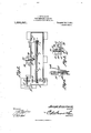
- Fi 3 is a detail view of the clamp showing the position a bit assumes during the tempering operation.
- Fig. 4; is a similar view of the clamp releasing mechanism to permit the bit to fall of its own weight exteriorly of the tempering tank.
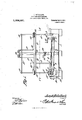
- the numeral 1 designates the tempering fluid retaining vat or tank, which is preferably of rectangular shape with an open end, the full length thereof, and has mounted centrally thereof to one side thereof thetubular column 2, and the upright arm or bracket 3 at the discharge end thereof.
- a collar 20 Surrounding the column or cylindrical support 2, is a collar 20, which has oppositely extending therefrom the arms or supports 21, provided with the longitudinally disposed guide plate 22, and mounted upon so as to rotate with the respective shafts 17 and 18 but permitted a sliding movement thereon, are the sprockets 23 and 24, which operate the endless chain 25, carrying thereon the bit receiving carriers or clamps 26, which are so disposed as to project beyond the guide strip 22, so that the bit A when having its cutting end resting within one of the receptacles or pans 9 of the belt 8, has its upper end received within one of the clamps 26 and held in a vertical position and prevented from inward movement by means of the guide 22, as the said belt or conveyers 8 and 25, respectively, pass from the entrance end to the exit end of the tank or reservoir 1.
- the supporting arms 21 carried by the collar 20 have their outer ends slidably mounted upon the respective shafts l7 and 18 and by means of the flexible cables or ropes 27 which pass over the oppositely disposed guide pulleys 28 at the top of the column or tubular support 2, and are position with relation to the water level in the tank 1, and therefore by reason of the fact that the endless belt inclines from the entrance to the exit end of the tank, that the water or tempering fluid level within 1 the tank or reservoir, 1, will cause the cutting end of the bit when in such perpendicular position with relation to the water level in the tank, to be gradually submerged at a varying depth from the entrance to the exit end of the tank, thus giving the lower cutting end a longer tempering and gradually decreasing the tempering operation from the lower end to the point according to the depth that the fluid has at the exit end of the tank.
- the bracket 31 is adjustably mounted within the tank 1, so that the crank 32 may be operated to raise or lower the shaft 5 and its sprocket 7, thereby using a greater or less incline of the belt 8 and getting the proper depth or submersion at the exit end of the tank or reservoir.
- the clamps 26 each comprise the attaching plates 33, connected to its proper link of the chain 25, and the plate 3 f having the arm 35 and the stationary jaw 36.
- a spring 37 Connected at one end to the arm 35 is a spring 37, attached to the lever 38 of the pivoted ja 39, the spring 37 normally exerting a tension to hold the jaw 39, and coact with the stationary jaw 36 to properly support the bit A during its travel.
- the curved guide 40 is engaged by the lever 38, causing the j aw 39 to assume the position as shown in dotted lines Fig.
- the guide 4E1 being disposed to engage the upper freed end of the bit A and not permit it to fall until the clamp 26 has rounded the sprocket 24 at which time the terminal 12 will permit the upper end of the bit A to fall outwardly and be discharged from the machine exteriorly of the tank.
- the belts 8 and 26 may be regulated to travel at any desired speed, and that the tank 1 may be decreased or diminished in length, to accommodate itself to tempering bits to the desired hardness, and that by reason of the adjustability of the belt 25, various lengths of bits may be accommodated and always be retained in a vertical and perpendicular position, so that the bit end or cutting end of the respective bits, will be properly submerged in the tempering fluid within the tank, so that said cut- 1 ting end may be tempered longer and to a harder degree than the remaining portion of the bit, the portion therefore being gradually tempered from the hardest to the toughest tempering desired.
- the bits although placed in position manually, are delivered automatically from the machine at the end of the tempering operation from where they may be gathered when desired.
- a tempering machine for bits or the like
- the combination with a tempering fluid reservoir of means for retaining the cutting end of the bits in tempering position within the fluid of the reservoir, said means being in a downwardly inclined position from the entrance to the exit end of the reservoir, means for holding the bit in a perpendicular position with relation to the level of the said liquid within the reservoir, and means for operating said retaining and holding means in unison.
- a tempering machine for bits or the like, the combination with a reservoir containing a tempering fluid, of an endless conveyer mounted in the reservoir and being in inclined relation to the level of the fluid therein, means carried by said conveyer for a receiving the cutting end of said bit, means 5 35 for holding the upper end of said bit so that the body of the bit assumes a perpendicular position with relation to the level of the liquid within the reservoir, and means for operating said conveying means and hold ing means in unison.
- a tempering machine for bits or the like the combination of a reservoir containing a tempering fluid, an endless conveyer mounted within the reservoir, means for ad justably mounting the exit end of said endless co-nveyer so as to regulate the depth thereof below the level of the tempering fluid within the reservoir, receptacles carried by said endless conveyer for receiving the cutting ends of the bits to be tempered, means operable above the reservoir and in parallel with the fluid therein for holding the respective bits in a position perpendicular to the level of the tempering fluid, and means for operating said bit holding means and the endless conveyer in unison.
- a tempering machine for bits or the like, the combination of a reservoir containing a tempering fluid, means for retaining the cutting ends of bits mounted within the reservoir and downwardly inclining below the level of the liquid therein from the entrance to the exit end of said reservoir, vertically adjustable means for holding the body of the bits in a perpendicular position with relation to the level of the liquid within the reservoir, and means for operating said retaining and holding means in unison.
- a tempering machine for bits or the like the combination with a reservoir containing a tempering fluid, of an endless conveyer belt mounted within the reservoir and downwardly inclining therein from the entrance to the exit end thereof and below the level of the tempering fluid within the reservoir, means carried thereby for receiving the cutting ends of the bits, another endless conveyer mounted above and parallel to the first mentioned endless conveyer, a series of clamps carried thereby for receiving the body of the bit and holding the same in a perpendicular position with relation to the fluid within the reservoir, and means for operating the two endless conveyer belts in unison.
- a tempering machine for bits or the like the combination with a reservoir containing a tempering fluid, of an endless conveyer belt journaled within the reservoir and downwardly inclining from the entrance to the exit end with relation to the level of the fluid within the reservoir, a series of receptacles mounted upon said'endless conveyer receiving the cutting ends of the bits, another endless conveyer adj ustably mounted with relation to the first mentioned endless conveyer, a series of bit receiving clamps carried thereby for retaining the respective bits in perpendicular position with relation to the level of the fluid within the reservoir, and means for operating said endless conveyers in unison.
- a tempering machine the combination of a reservoir containing a tempering fluid, an endless conveyer belt journaled therein, means for vertically adjusting the exit end of said endless conveyer belt, another endless conveyer belt journaled above the belt, said belt coacting to receive and retain a bit in a position perpendicular to the level of the fluid in the reservoir, and means for operating said conveyer belts in unison.
- a tempering machine for bits or the like the combination of a reservoir containing a tempering fluid, two endless conveyer belts mounted for simultaneous operation and mounted with relation to the fluid within the reservoir so that the body of the bit is sustained in a perpendicular position with relation to the fluid in the reservoir and so that the cutting end of the bit is gradually submerged in the tempering fluid from the entrance to the exit end of the reservoir, and means for operating said conveying means in umson.
- an endless conveyer belt journaled upon said shaft and adapted to have the upper lead thereof downwardly inclined from the entrance end to the exit end with relation to the level of the fluid within the reservoir, a series of bit receiving receptacles carried by said conveyer belt, and means for operating said conveyer belt.
- a tempering machine the combination of a reservoir containing a tempering fluid, a shaft transversely journaled at the entrance end thereof, another shaft parallel thereto adjustably mounted within the reservoir near the exit end thereof, an endless conveyer belt ournaled upon said shaft and adapted to have the upper;- lead thereof downwardly inclined from the entrance end to the exit end with relation to the level of the fluid within the reservoir, a series of bit receiving receptacles carried by said conveyer belt, means for operating said conveyer belt, apair of vertically disposed shafts journaled with relation to the reservoir, one of said shafts being operably connected to the first mentioned transverse shaft, and a bit holding conveyer belt journaled upon said vertical shaft for retaining the body of the bit in a perpendicular position with relation to the level of the fluid within the reservoir.
- a tempering machine the combination of a reservoir containing a tempering fluid, a shaft transversely journaled at the entrance end thereof, another shaft parallel thereto adjustably mounted within the reservoir near the exit end thereof, an endless conveyer belt journaled upon said shaft and adapted to have the upper lead thereof downwardly inclined from the entrance end to the exit end with relation to the level of the fluid within the reservoir, a series of bit receiving receptacles carried by said conveyer belt, means for operating said conveyer belt, a support, a pair of vertical shafts, one of said shafts being operably connected to the first mentioned transverse shaft, an oppositely extending frame adjustably mounted upon said support and having its ends slidably mounted upon said vertical shaft, and an endless conveyer belt operably connected to said vertical shaft and slidable with the frame thereon, for retaining the body of the bits in a position perpendicular to the level of the fluid within the reservoir.
- a tempering machine the combination of a reservoir containing tempering fluid, a shaft transversely journaled at the entrance end thereof, another shaft parallel thereto adjustably mounted within the reservoir near the exit end thereof, an end less conveyer belt journaled upon said shaft and adapted to have the upper lead thereof downwardly inclined from the entrance end to the exit end with relation to the level of the fluid within the reservoir, a series of bit receiving receptacles carried by said conveyer belt, means for operating said conveyer belt, a support, a pair of vertical shafts, one of said shafts being operably connected to the first mentioned transverse shaft, an oppositely extending frame adjustably mounted upon said support and having its ends slidably mounted upon said vertical shaft, an endless conveyer belt operably connected to said vertical shaft and slidable with the frame thereon, for retaining the body of the bits in a position perpendicular to the level of the fluid within the reservoir, and means for raising and lowering the last mentioned endless belt and its supporting frame so as to accommodate various lengths of bits.
- a tempering machine the combination of a reservoir containing a tempering fluid, a shaft mounted transversely of the reservoir at the entrance end thereof, a motor operably connected to said shaft, another shaft mounted within the reservoir and in parallel with the first mentioned transverse shaft, means for varying the submergence of said.
- an endless conveyer operably connected to both of said transverse shafts, series of bit receiving receptacles carried by said endless conveyer, a tubular support, a pair'of arms stationarily mounted to the upper ends of said support and projecting in opposite directions therefrom, a vertical shaft journaled at the entrance end of the reservoir and in one end of said arm, another vertical shaft ournaled at the other end of the reservoir and to the other end of the said arm, a frame slidably mounted on said tubular support and interposed between the said arms and the reservoir, another endless conveyer belt operably connected to said vertical shafts and ad justable thereon with said last mentioned frame, and a series of bit receiving clamps carried by said last mentioned endless conveyer belt for receiving the body of the bit and retaining them in a perpendicular position with relation to the level of the fluid within the reservoir during the travel of the said belt from the entrance to the exit end of the reservoir.
- a tempering machine the combination of a reservoir containing a tempering fluid, a shaft mounted transversely of the reservoir at the entrance end thereof, a motor operably connected to said shaft, another shaft mounted within the reservoir and in parallel with the first mentioned transverse shaft, means for varying the sub mergence of said last mentioned shaft within the liquid within the reservoir, an endless conveyer operably connected to both of said transverse shafts, series of bit receiving receptacles carried by said endless conveyer, a tubular sup ort, a pair of arms stationarily mounted to t e upper ends of said support and projecting in opposite directions therefrom, a Vertical shaft journaled at the entrance end of the reservoir and in one end of said arm, another vertical shaft journaled at the other end of the reservoir and to the other end of the said arm, a frame slidably mounted on said tubular support and interposed between the said arms and the reservoir, another endless conveyer belt operably connected to said vertical shafts and adjustable thereon with said last mentioned frame, a series of bit receiving clamp
- a tempering machine the combination of a reservoir containing a tempering fluid, a shaft mounted transversely ofthe reservoir at the entrance end thereof, a motor operably connected to said shaft, another shaft mounted within the reservoir and in parallel with the first mentioned transverse shaft, means for varying the sub mergence of said last mentioned shaft within the liquid within the reservoir, an endless conveyer operably connected to both of said transverse shafts, a series of bit receiving receptacles carried by said endless conveyor, a tubular support, a pair of arms stationarily mounted to the upper ends of said support and projecting in opposite directions therefrom a vertical shaft journaled at the entrance end of the reservoir and in one end of said arm, another vertical shaft journaled at the other end of the reservoir and to the other end of the said arm, a frame slidably mounted on said tubular support and interposed between the said arms and the reservoir, another endless conveyer belt operably connected to said vertical shafts and adjustable thereon with said last mentioned frame, a series of bit receiving clamps carried by said last mentioned endless
Landscapes
- Life Sciences & Earth Sciences (AREA)
- Chemical & Material Sciences (AREA)
- Engineering & Computer Science (AREA)
- Food Science & Technology (AREA)
- Polymers & Plastics (AREA)
- Treatment Of Fiber Materials (AREA)
Description
J. RETALLAGK.
TIME TEMPBBING MACHINE. APPLICATION mum m}: an. 1011.
Patented Oct. 3, 1911.
2 SHEETS-BEBE! 1.
W I TINW 11 1 1 1 k\ 1 1 1 a N In ventor by W I Atto rneys EOLUMIIA PUNOORAPH C0,. WASNlNOTON. D. C.
Witnesses J. RETALLAGK.
TIME TEMPERING MACHINE.
111 2110111011 FILED 111111130, 1911.
1,004,591. Patented 0013,1911.
2 SHEETS-SHEET 2.
Inventor W Attorneys Witnesses UNITED STATES PATENT OFFICE.
JOSEPH RETALLACK, OF DENVER, COLORADO.
TIME TEMPERING-MACHINE.
To all whom it may concern.
Be it known that I, JOSEPH Rn'rALLAoK, a citizen of the United States, residing at Denver, in the county of Denver and State of Colorado, have invented a new and useful Time Tempering-Machine, of which the following is a specification.
This invention relates to improvements in time tempering machines the primary object of the invention being the provision of a machine whereby the cutting or entering end of bits may be properly tempered from the extreme cutting point thereof to a predetermined distance beyond the same, the said machine being provided with means for receiving and holding the said head in an upright position, and delivering it to a tempering liquid gradually increasing the submergence of the cutting end of the bit, until the same is tempered for the proper length of time, at which time the bit is released and permitted to fall by gravity exteriorly of the tempering fluid.
A further object of this invention, is the provision of a machine of this character provided with a vat or tank containing the tempering fluid, and an endless belt conveyer mounted inclinedly within the body of tempering fluid whereby the ends of the bits are so disposed and travel with said endless belt to be presented at a gradually increased depth within the tempering fluid, a simultaneously operated endless clamping device being so mounted and disposed with regard to the submerging endless belt, that the bits are retained in an upright position, to insure the even submergence within the tempering fluid, and to also permit the upper end of the bit to be released at the proper time, when the cutting ends of the bits have been properly tempered and have traveled a sufficient or desired distance within the tempering fluid within the tank.
With the foregoing and other objects in view which will appear as the description proceeds, the invention resides in the combination and arrangement of parts and in the details of construction hereinafter described and claimed, it being understood Specification of Letters Patent.
Application filed June 30, 1911.
Patented Oct. 3, 1911.
Serial No. 636,151.
tempering apparatus in operable relation therewith. Fig. 2 is a top plan view of the vat, with the lower bit receiving and carrying endless belt with its operating mechanism. Fi 3 is a detail view of the clamp showing the position a bit assumes during the tempering operation. Fig. 4; is a similar view of the clamp releasing mechanism to permit the bit to fall of its own weight exteriorly of the tempering tank.
Referring to the drawings, the numeral 1 designates the tempering fluid retaining vat or tank, which is preferably of rectangular shape with an open end, the full length thereof, and has mounted centrally thereof to one side thereof thetubular column 2, and the upright arm or bracket 3 at the discharge end thereof.
J ournaled transversely at the entrance end of the vat or tank, is a shaft 4, while journaled in the bracket 31 near the other end of the vat or tank is a shaft 5, the same projecting into the vat and parallel with the shaft 4, but at a lower level within the tank, so that the respective sprocket wheels 6 and 7, which carry the endless conveying belt 8 will cause the said conveying belt to have its upper lead inclined from the entrance to the exit end of the tank or reservoir, the level of the tempering liquid within the vat 1 being approximately upon the dotted lines in Fig. 1, whereby the entrance end of the conveyor belt 8 is slightly above the level while the exit end thereof will be below the level.
Mounted at equidistances and carried by the endless belt 8, are the bit receiving receptacles or pans 9, of such a shape as to receive the lower end of the bit A, and as the said belt 8 moves from the entrance to the exit end of the tank, the said bit A being held in an upright position, has its cutting or lower end mounted in one of the pans or receptacles 9 submerged within the tank, the depth of the submergence being gradual from the entrance end to the exit end of the Y 14, whereby motion is transmitted to the elements of the machine.
Journaled within the bracket 16 and having the lower pinion 16 thereof meshing with the pinion 10, is the main drive and vertical shaft 17, while the parallel arranged guiding shaft 18 is journaled in the upper end of the bracket or support 3. Both of these shafts 17 and 18 have their upper ends j ournaled at 19 in the bearings in the outer ends of the support 19 supported at the upper end of the column 2.
Surrounding the column or cylindrical support 2, is a collar 20, which has oppositely extending therefrom the arms or supports 21, provided with the longitudinally disposed guide plate 22, and mounted upon so as to rotate with the respective shafts 17 and 18 but permitted a sliding movement thereon, are the sprockets 23 and 24, which operate the endless chain 25, carrying thereon the bit receiving carriers or clamps 26, which are so disposed as to project beyond the guide strip 22, so that the bit A when having its cutting end resting within one of the receptacles or pans 9 of the belt 8, has its upper end received within one of the clamps 26 and held in a vertical position and prevented from inward movement by means of the guide 22, as the said belt or conveyers 8 and 25, respectively, pass from the entrance end to the exit end of the tank or reservoir 1. The upper end of the bit being relieved from the clamp 26 as the pan 9 carrying the lower end thereof passes above and starts around the sprocket wheel 7 thus causing the upper end of the bit A to tilt or incline so that it will assume the position of dotted lines in Fig. l, and by reason of the greater length thereof projecting ex teriorly of the tank, said bit will tilt and fall beyond and without the tank and thereby be automatically released and delivered after having its cutting or lower end properly tempered.
In order to accommodate this machine to various length bits, the supporting arms 21 carried by the collar 20, have their outer ends slidably mounted upon the respective shafts l7 and 18 and by means of the flexible cables or ropes 27 which pass over the oppositely disposed guide pulleys 28 at the top of the column or tubular support 2, and are position with relation to the water level in the tank 1, and therefore by reason of the fact that the endless belt inclines from the entrance to the exit end of the tank, that the water or tempering fluid level within 1 the tank or reservoir, 1, will cause the cutting end of the bit when in such perpendicular position with relation to the water level in the tank, to be gradually submerged at a varying depth from the entrance to the exit end of the tank, thus giving the lower cutting end a longer tempering and gradually decreasing the tempering operation from the lower end to the point according to the depth that the fluid has at the exit end of the tank.
In order to regulate the depth to which it is desired to temper the bit, the bracket 31 is adjustably mounted within the tank 1, so that the crank 32 may be operated to raise or lower the shaft 5 and its sprocket 7, thereby using a greater or less incline of the belt 8 and getting the proper depth or submersion at the exit end of the tank or reservoir.
As clearly shown in Fig. 3, the clamps 26 each comprise the attaching plates 33, connected to its proper link of the chain 25, and the plate 3 f having the arm 35 and the stationary jaw 36. Connected at one end to the arm 35 is a spring 37, attached to the lever 38 of the pivoted ja 39, the spring 37 normally exerting a tension to hold the jaw 39, and coact with the stationary jaw 36 to properly support the bit A during its travel. As the clamp 26, is moved opposite the discharge end, the curved guide 40, is engaged by the lever 38, causing the j aw 39 to assume the position as shown in dotted lines Fig. 3, the guide 4E1, being disposed to engage the upper freed end of the bit A and not permit it to fall until the clamp 26 has rounded the sprocket 24 at which time the terminal 12 will permit the upper end of the bit A to fall outwardly and be discharged from the machine exteriorly of the tank.
From the foregoing description it is evident that the belts 8 and 26 may be regulated to travel at any desired speed, and that the tank 1 may be decreased or diminished in length, to accommodate itself to tempering bits to the desired hardness, and that by reason of the adjustability of the belt 25, various lengths of bits may be accommodated and always be retained in a vertical and perpendicular position, so that the bit end or cutting end of the respective bits, will be properly submerged in the tempering fluid within the tank, so that said cut- 1 ting end may be tempered longer and to a harder degree than the remaining portion of the bit, the portion therefore being gradually tempered from the hardest to the toughest tempering desired. By this construction it is also evident that the bits although placed in position manually, are delivered automatically from the machine at the end of the tempering operation from where they may be gathered when desired.
What is claimed is 1. In a tempering machine for bits or the like, the combination with a tempering fluid reservoir, of means for retaining the cutting ends of the bits in tempering position within the fluid of the reservoir, means for holding the bits in a perpendicular position with relation to the level of said liquid within the reservoir, and means for operating said retaining and holding means in unison.
2. In a tempering machine for bits or the like, the combination with a tempering fluid reservoir, of means for retaining the cutting end of the bits in tempering position within the fluid of the reservoir, said means being in a downwardly inclined position from the entrance to the exit end of the reservoir, means for holding the bit in a perpendicular position with relation to the level of the said liquid within the reservoir, and means for operating said retaining and holding means in unison.
3. In a tempering machine for bits or the like, the combination with a reservoir containing a tempering fluid, of an endless conveyer mounted in the reservoir and being in inclined relation to the level of the fluid therein, means carried by said conveyer for a receiving the cutting end of said bit, means 5 35 for holding the upper end of said bit so that the body of the bit assumes a perpendicular position with relation to the level of the liquid within the reservoir, and means for operating said conveying means and hold ing means in unison.
at. In a tempering machine for bits or the like, the combination of a reservoir containing a tempering fluid, an endless conveyer mounted within the reservoir, means for ad justably mounting the exit end of said endless co-nveyer so as to regulate the depth thereof below the level of the tempering fluid within the reservoir, receptacles carried by said endless conveyer for receiving the cutting ends of the bits to be tempered, means operable above the reservoir and in parallel with the fluid therein for holding the respective bits in a position perpendicular to the level of the tempering fluid, and means for operating said bit holding means and the endless conveyer in unison.
5. In a tempering machine for bits or the like, the combination of a reservoir containing a tempering fluid, means for retaining the cutting ends of bits mounted within the reservoir and downwardly inclining below the level of the liquid therein from the entrance to the exit end of said reservoir, vertically adjustable means for holding the body of the bits in a perpendicular position with relation to the level of the liquid within the reservoir, and means for operating said retaining and holding means in unison.
6. In a tempering machine for bits or the like, the combination with a reservoir containing a tempering fluid, of an endless conveyer belt mounted within the reservoir and downwardly inclining therein from the entrance to the exit end thereof and below the level of the tempering fluid within the reservoir, means carried thereby for receiving the cutting ends of the bits, another endless conveyer mounted above and parallel to the first mentioned endless conveyer, a series of clamps carried thereby for receiving the body of the bit and holding the same in a perpendicular position with relation to the fluid within the reservoir, and means for operating the two endless conveyer belts in unison.
7. In a tempering machine for bits or the like, the combination with a reservoir containing a tempering fluid, of an endless conveyer belt journaled within the reservoir and downwardly inclining from the entrance to the exit end with relation to the level of the fluid within the reservoir, a series of receptacles mounted upon said'endless conveyer receiving the cutting ends of the bits, another endless conveyer adj ustably mounted with relation to the first mentioned endless conveyer, a series of bit receiving clamps carried thereby for retaining the respective bits in perpendicular position with relation to the level of the fluid within the reservoir, and means for operating said endless conveyers in unison.
8. In a tempering machine, the combination of a reservoir containing a tempering fluid, an endless conveyer belt journaled therein, means for vertically adjusting the exit end of said endless conveyer belt, another endless conveyer belt journaled above the belt, said belt coacting to receive and retain a bit in a position perpendicular to the level of the fluid in the reservoir, and means for operating said conveyer belts in unison.
9. In a tempering machine for bits or the like, the combination of a reservoir containing a tempering fluid, two endless conveyer belts mounted for simultaneous operation and mounted with relation to the fluid within the reservoir so that the body of the bit is sustained in a perpendicular position with relation to the fluid in the reservoir and so that the cutting end of the bit is gradually submerged in the tempering fluid from the entrance to the exit end of the reservoir, and means for operating said conveying means in umson.
10. In a tempering machine, the combination of a reservoir containing a tempering fluid, a shaft transversely journaled at the entrance end thereof, another shaft paral- &
lel thereto adjustably mounted within the reservoir near the exit end thereof, an endless conveyer belt journaled upon said shaft and adapted to have the upper lead thereof downwardly inclined from the entrance end to the exit end with relation to the level of the fluid within the reservoir, a series of bit receiving receptacles carried by said conveyer belt, and means for operating said conveyer belt.
11. In a tempering machine, the combination of a reservoir containing a tempering fluid, a shaft transversely journaled at the entrance end thereof, another shaft parallel thereto adjustably mounted within the reservoir near the exit end thereof, an endless conveyer belt ournaled upon said shaft and adapted to have the upper;- lead thereof downwardly inclined from the entrance end to the exit end with relation to the level of the fluid within the reservoir, a series of bit receiving receptacles carried by said conveyer belt, means for operating said conveyer belt, apair of vertically disposed shafts journaled with relation to the reservoir, one of said shafts being operably connected to the first mentioned transverse shaft, and a bit holding conveyer belt journaled upon said vertical shaft for retaining the body of the bit in a perpendicular position with relation to the level of the fluid within the reservoir.
12. In a tempering machine, the combination of a reservoir containing a tempering fluid, a shaft transversely journaled at the entrance end thereof, another shaft parallel thereto adjustably mounted within the reservoir near the exit end thereof, an endless conveyer belt journaled upon said shaft and adapted to have the upper lead thereof downwardly inclined from the entrance end to the exit end with relation to the level of the fluid within the reservoir, a series of bit receiving receptacles carried by said conveyer belt, means for operating said conveyer belt, a support, a pair of vertical shafts, one of said shafts being operably connected to the first mentioned transverse shaft, an oppositely extending frame adjustably mounted upon said support and having its ends slidably mounted upon said vertical shaft, and an endless conveyer belt operably connected to said vertical shaft and slidable with the frame thereon, for retaining the body of the bits in a position perpendicular to the level of the fluid within the reservoir.
13. In a tempering machine, the combination of a reservoir containing tempering fluid, a shaft transversely journaled at the entrance end thereof, another shaft parallel thereto adjustably mounted within the reservoir near the exit end thereof, an end less conveyer belt journaled upon said shaft and adapted to have the upper lead thereof downwardly inclined from the entrance end to the exit end with relation to the level of the fluid within the reservoir, a series of bit receiving receptacles carried by said conveyer belt, means for operating said conveyer belt, a support, a pair of vertical shafts, one of said shafts being operably connected to the first mentioned transverse shaft, an oppositely extending frame adjustably mounted upon said support and having its ends slidably mounted upon said vertical shaft, an endless conveyer belt operably connected to said vertical shaft and slidable with the frame thereon, for retaining the body of the bits in a position perpendicular to the level of the fluid within the reservoir, and means for raising and lowering the last mentioned endless belt and its supporting frame so as to accommodate various lengths of bits.
14. In a tempering machine, the combination of a reservoir containing a tempering fluid, a shaft mounted transversely of the reservoir at the entrance end thereof, a motor operably connected to said shaft, another shaft mounted within the reservoir and in parallel with the first mentioned transverse shaft, means for varying the submergence of said. last mentioned shaft within the liquid within the reservoir, an endless conveyer operably connected to both of said transverse shafts, series of bit receiving receptacles carried by said endless conveyer, a tubular support, a pair'of arms stationarily mounted to the upper ends of said support and projecting in opposite directions therefrom, a vertical shaft journaled at the entrance end of the reservoir and in one end of said arm, another vertical shaft ournaled at the other end of the reservoir and to the other end of the said arm, a frame slidably mounted on said tubular support and interposed between the said arms and the reservoir, another endless conveyer belt operably connected to said vertical shafts and ad justable thereon with said last mentioned frame, and a series of bit receiving clamps carried by said last mentioned endless conveyer belt for receiving the body of the bit and retaining them in a perpendicular position with relation to the level of the fluid within the reservoir during the travel of the said belt from the entrance to the exit end of the reservoir.
15. In a tempering machine, the combination of a reservoir containing a tempering fluid, a shaft mounted transversely of the reservoir at the entrance end thereof, a motor operably connected to said shaft, another shaft mounted within the reservoir and in parallel with the first mentioned transverse shaft, means for varying the sub mergence of said last mentioned shaft within the liquid within the reservoir, an endless conveyer operably connected to both of said transverse shafts, series of bit receiving receptacles carried by said endless conveyer, a tubular sup ort, a pair of arms stationarily mounted to t e upper ends of said support and projecting in opposite directions therefrom, a Vertical shaft journaled at the entrance end of the reservoir and in one end of said arm, another vertical shaft journaled at the other end of the reservoir and to the other end of the said arm, a frame slidably mounted on said tubular support and interposed between the said arms and the reservoir, another endless conveyer belt operably connected to said vertical shafts and adjustable thereon with said last mentioned frame, a series of bit receiving clamps carriedby said last mentioned endless conveyer beltfor receiving the body of the bit and retaining them in a perpendicular position with relation to the level of the fluid within the reservoir during the travel of the said belt from the entrance to the exit end of the reservoir, and means for adjusting said frame upon the tubular member and regulating the distance of the endless conveyer carried thereby with relation to the level of the fluid within the reservoir.
16. In a tempering machine, the combination of a reservoir containing a tempering fluid, a shaft mounted transversely ofthe reservoir at the entrance end thereof, a motor operably connected to said shaft, another shaft mounted within the reservoir and in parallel with the first mentioned transverse shaft, means for varying the sub mergence of said last mentioned shaft within the liquid within the reservoir, an endless conveyer operably connected to both of said transverse shafts, a series of bit receiving receptacles carried by said endless conveyor, a tubular support, a pair of arms stationarily mounted to the upper ends of said support and projecting in opposite directions therefrom a vertical shaft journaled at the entrance end of the reservoir and in one end of said arm, another vertical shaft journaled at the other end of the reservoir and to the other end of the said arm, a frame slidably mounted on said tubular support and interposed between the said arms and the reservoir, another endless conveyer belt operably connected to said vertical shafts and adjustable thereon with said last mentioned frame, a series of bit receiving clamps carried by said last mentioned endless conveyer belt for receiving the body of the bits and retaining them in a perpendicular position with relation to the level of the fluid within the reservoir during the travel of the said belt from the entrance to the exit end of the reservoir, and a guiding means carried by said frame upon the tubular member for causing the upper free ends of the bits to be released and projected from the reservoir, as the bits approach the exit end of the reservoir.
In testimony that I claim the foregoing as my own, I have hereto aflixed my signature in the presence of two witnesses.
JOSEPH RETALLAOK.
Witnesses:
E. A. STEOKEL, F. W. CorrERILL.
Copies of this patent may be obtained for five cents each, by addressing the Commissioner of Patents, Washington, D. G.
Priority Applications (1)
| Application Number | Priority Date | Filing Date | Title |
|---|---|---|---|
| US63615111A US1004591A (en) | 1911-06-30 | 1911-06-30 | Time tempering-machine. |
Applications Claiming Priority (1)
| Application Number | Priority Date | Filing Date | Title |
|---|---|---|---|
| US63615111A US1004591A (en) | 1911-06-30 | 1911-06-30 | Time tempering-machine. |
Publications (1)
| Publication Number | Publication Date |
|---|---|
| US1004591A true US1004591A (en) | 1911-10-03 |
Family
ID=3072905
Family Applications (1)
| Application Number | Title | Priority Date | Filing Date |
|---|---|---|---|
| US63615111A Expired - Lifetime US1004591A (en) | 1911-06-30 | 1911-06-30 | Time tempering-machine. |
Country Status (1)
| Country | Link |
|---|---|
| US (1) | US1004591A (en) |
-
1911
- 1911-06-30 US US63615111A patent/US1004591A/en not_active Expired - Lifetime
Similar Documents
| Publication | Publication Date | Title |
|---|---|---|
| US1004591A (en) | Time tempering-machine. | |
| DK141154B (en) | Apparatus for blanching of shelled edible nodes. | |
| US1361832A (en) | Unloading apparatus | |
| US1335076A (en) | Conveyer | |
| US1754612A (en) | Liquid-bath apparatus | |
| US1332292A (en) | Cane-shifting apparatus | |
| US612413A (en) | guernsey | |
| US973059A (en) | Barrel-sanding apparatus. | |
| US2275335A (en) | Potato sacking machine | |
| US1415506A (en) | Washing machine | |
| US548964A (en) | Apparatus for lifting fishing nets or lines | |
| US1028823A (en) | Fruit-elevator. | |
| US1641970A (en) | Sealing machine | |
| US1109963A (en) | Freight-handling apparatus. | |
| US671421A (en) | Fish-dressing machine. | |
| US1048487A (en) | Intestine-cleaning machine. | |
| US706033A (en) | Apparatus for washing fat. | |
| US802061A (en) | Machine for automatically shaping masses of dough to the forms required for loaves. | |
| US1135127A (en) | Brick cleaning and refacing machine. | |
| US562824A (en) | hillman | |
| US661197A (en) | Conveyer. | |
| US630279A (en) | Straw-stacker. | |
| US411349A (en) | Washing-machine | |
| US741300A (en) | Apparatus for the removal and dumping of spent tanbark. | |
| US775015A (en) | Fruit-grader. |