US10041256B2 - Undercut clip anchor system for cladding of materials - Google Patents
Undercut clip anchor system for cladding of materials Download PDFInfo
- Publication number
- US10041256B2 US10041256B2 US14/884,734 US201514884734A US10041256B2 US 10041256 B2 US10041256 B2 US 10041256B2 US 201514884734 A US201514884734 A US 201514884734A US 10041256 B2 US10041256 B2 US 10041256B2
- Authority
- US
- United States
- Prior art keywords
- mounting
- undercut
- upward projection
- wall portion
- clip
- Prior art date
- Legal status (The legal status is an assumption and is not a legal conclusion. Google has not performed a legal analysis and makes no representation as to the accuracy of the status listed.)
- Active
Links
Images


Classifications
-
- E—FIXED CONSTRUCTIONS
- E04—BUILDING
- E04F—FINISHING WORK ON BUILDINGS, e.g. STAIRS, FLOORS
- E04F13/00—Coverings or linings, e.g. for walls or ceilings
- E04F13/07—Coverings or linings, e.g. for walls or ceilings composed of covering or lining elements; Sub-structures therefor; Fastening means therefor
- E04F13/08—Coverings or linings, e.g. for walls or ceilings composed of covering or lining elements; Sub-structures therefor; Fastening means therefor composed of a plurality of similar covering or lining elements
- E04F13/0801—Separate fastening elements
- E04F13/0803—Separate fastening elements with load-supporting elongated furring elements between wall and covering elements
- E04F13/081—Separate fastening elements with load-supporting elongated furring elements between wall and covering elements with additional fastening elements between furring elements and covering elements
-
- E—FIXED CONSTRUCTIONS
- E04—BUILDING
- E04B—GENERAL BUILDING CONSTRUCTIONS; WALLS, e.g. PARTITIONS; ROOFS; FLOORS; CEILINGS; INSULATION OR OTHER PROTECTION OF BUILDINGS
- E04B1/00—Constructions in general; Structures which are not restricted either to walls, e.g. partitions, or floors or ceilings or roofs
- E04B1/38—Connections for building structures in general
- E04B1/388—Separate connecting elements
-
- E04B1/40—
-
- E—FIXED CONSTRUCTIONS
- E04—BUILDING
- E04F—FINISHING WORK ON BUILDINGS, e.g. STAIRS, FLOORS
- E04F13/00—Coverings or linings, e.g. for walls or ceilings
- E04F13/07—Coverings or linings, e.g. for walls or ceilings composed of covering or lining elements; Sub-structures therefor; Fastening means therefor
- E04F13/08—Coverings or linings, e.g. for walls or ceilings composed of covering or lining elements; Sub-structures therefor; Fastening means therefor composed of a plurality of similar covering or lining elements
- E04F13/0801—Separate fastening elements
- E04F13/0803—Separate fastening elements with load-supporting elongated furring elements between wall and covering elements
- E04F13/0805—Separate fastening elements with load-supporting elongated furring elements between wall and covering elements with additional fastening elements between furring elements and the wall
- E04F13/0807—Separate fastening elements with load-supporting elongated furring elements between wall and covering elements with additional fastening elements between furring elements and the wall adjustable perpendicular to the wall
-
- E—FIXED CONSTRUCTIONS
- E04—BUILDING
- E04F—FINISHING WORK ON BUILDINGS, e.g. STAIRS, FLOORS
- E04F13/00—Coverings or linings, e.g. for walls or ceilings
- E04F13/07—Coverings or linings, e.g. for walls or ceilings composed of covering or lining elements; Sub-structures therefor; Fastening means therefor
- E04F13/08—Coverings or linings, e.g. for walls or ceilings composed of covering or lining elements; Sub-structures therefor; Fastening means therefor composed of a plurality of similar covering or lining elements
- E04F13/0801—Separate fastening elements
- E04F13/0803—Separate fastening elements with load-supporting elongated furring elements between wall and covering elements
- E04F13/081—Separate fastening elements with load-supporting elongated furring elements between wall and covering elements with additional fastening elements between furring elements and covering elements
- E04F13/0816—Separate fastening elements with load-supporting elongated furring elements between wall and covering elements with additional fastening elements between furring elements and covering elements the additional fastening elements extending into the back side of the covering elements
-
- E—FIXED CONSTRUCTIONS
- E04—BUILDING
- E04F—FINISHING WORK ON BUILDINGS, e.g. STAIRS, FLOORS
- E04F13/00—Coverings or linings, e.g. for walls or ceilings
- E04F13/07—Coverings or linings, e.g. for walls or ceilings composed of covering or lining elements; Sub-structures therefor; Fastening means therefor
- E04F13/08—Coverings or linings, e.g. for walls or ceilings composed of covering or lining elements; Sub-structures therefor; Fastening means therefor composed of a plurality of similar covering or lining elements
- E04F13/0801—Separate fastening elements
- E04F13/0803—Separate fastening elements with load-supporting elongated furring elements between wall and covering elements
- E04F13/081—Separate fastening elements with load-supporting elongated furring elements between wall and covering elements with additional fastening elements between furring elements and covering elements
- E04F13/083—Hooking means on the back side of the covering elements
-
- E—FIXED CONSTRUCTIONS
- E04—BUILDING
- E04F—FINISHING WORK ON BUILDINGS, e.g. STAIRS, FLOORS
- E04F13/00—Coverings or linings, e.g. for walls or ceilings
- E04F13/07—Coverings or linings, e.g. for walls or ceilings composed of covering or lining elements; Sub-structures therefor; Fastening means therefor
- E04F13/08—Coverings or linings, e.g. for walls or ceilings composed of covering or lining elements; Sub-structures therefor; Fastening means therefor composed of a plurality of similar covering or lining elements
- E04F13/14—Coverings or linings, e.g. for walls or ceilings composed of covering or lining elements; Sub-structures therefor; Fastening means therefor composed of a plurality of similar covering or lining elements stone or stone-like materials, e.g. ceramics concrete; of glass or with an outer layer of stone or stone-like materials or glass
Definitions
- the exemplary teachings herein pertain to method(s), system(s) and device(s) used in the field of anchorage systems for facades or cladding of materials, for example as may be disclosed in U.S. Pat. No. 8,365,481, the entire disclosure of which is herein incorporated by reference.
- the exemplary technique(s), system(s), device(s) and method(s) presented herein to an undercut clip anchor system for cladding of materials comprises only one horizontal rail (“H 3 ”) per row stone, whereas other known undercut anchoring systems incorporate two horizontal rails per row of stone. Serrations on the undercut clip (“UCC”) and nut bar serrated washer (“NB 3 ”) allow for adjustments needed to accommodate for stone tolerances; or if the undercut clips were not installed correctly (due to human error), they can easily be adjusted. The undercut clips cannot be seen through the joints in the cladding material.
- the unique bolt/nut/track design disclosed herein allows for highly accurate adjustment of stones vertically.
- the undercut clip anchor system of the present disclosure provides for accurate installation of panel cladding materials (natural stone, porcelain, concrete, etc.). Further, the undercut clips are not seen through the horizontal joint between panels. Additionally, only one horizontal rail is needed and used per row of stone. Also, a single rail supports the weight the stone below it and restrains the stone above it from rotation. The system allows for cladding of thinner materials (less than 3 cm) that cannot be anchored at the top, bottom, or sides. A unique bolt/nut/track design allows for highly accurate adjustment of stones vertically. Serrations on the UCC and NB 3 allow for adjustments needed to accommodate for stone tolerances or installation errors. The minimal amount of different pieces used in the systems minimizes confusion and makes installation relative quick and easy.
- M 3 refers to mullion
- HLC refers to horizontal lock clip
- MSC mullion support
- clip UCC 1 refers to undercut clip
- NE 2 refers to blockwork
- H 4 refers to horizontal rail
- INS refers to insulation
- NE 1 refers to concrete slap
- F 01 refers to M 12 expansion bolt
- WT 1 refers to wall tie anchor
- SB 1 refers to slide bar
- F 31 refers to self-drilling screw
- NB 1 refers to nut bar
- F 21 refers to DIN933 M 12 ⁇ 25 bolt
- UM 1 refers to M 1 mullion splice
- DPC refers to damp proof course.
- FIG. 1 is an enlarged side view of the H 3 horizontal rail of the disclosed system.
- FIG. 2 is a side view of the alternate H 3 . 1 horizontal rail.
- FIG. 3 is a side view of the UCC 1 undercut clip of the disclosed system.
- FIG. 4A is a perspective view of the UCC 2 undercut clip of the disclosed system.
- FIG. 4B is a side view of the UCC 2 undercut clip.
- FIG. 5 is a side view of the undercut clip anchor system of the present disclosure in use.
- FIG. 6A is a partially cut away perspective view of the undercut clip anchor system of the present disclosure in use.
- FIG. 6B is a front view of the undercut clip anchor system of FIG. 6A .
- FIG. 6C is a side view of the undercut clip anchor system of FIG. 6A .
- FIG. 6D is a top view of the undercut clip anchor system of FIG. 6A .
- FIGS. 7A-7F are views illustrating typical system dimensions of the undercut clip anchor system of the present disclosure in use.
- FIG. 8 is a view illustrating typical dead load anchor detail of the undercut clip anchor system of the present disclosure in use.
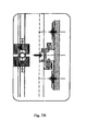
- FIG. 9 is a view illustrating typical mullion splice detail of the undercut clip anchor system of the present disclosure in use.
- FIG. 10 is a view illustrating typical wind load anchor detail of the undercut clip anchor system of the present disclosure in use.
- FIG. 11 is a view illustrating typical bottom clip detail of the undercut clip anchor system of the present disclosure in use.
- FIG. 12 is a view illustrating typical intermediate clip detail of the undercut clip anchor system of the present disclosure in use.
- FIG. 13 is a view illustrating typical top clip detail of the undercut clip anchor system the present disclosure in use.
- FIG. 14 is a view illustrating typical dead load anchor plan of the undercut clip anchor system of the present disclosure in use.
- the disclosed undercut clip anchor system comprises one or more of the following components, including without limitation: H 3 or H 3 . 1 horizontal rail, UCC 1 or UCC 2 undercut clips, NB 3 nut bar serrated washer, undercut anchor such as Keil, GSD, or similar, bolt(s), e.g., 6 mm ⁇ 40 mm hex head machine bolt, nut(s), e.g., 6 mm nut, and structural silicone or similar.
- H 3 or H 3 . 1 horizontal rail UCC 1 or UCC 2 undercut clips
- NB 3 nut bar serrated washer undercut anchor such as Keil, GSD, or similar
- bolt(s) e.g., 6 mm ⁇ 40 mm hex head machine bolt
- nut(s) e.g., 6 mm nut
- structural silicone or similar structural silicone or similar.
- the H 3 horizontal rail is attached to a back-up wall (metal stud, CMU, or concrete).
- a back-up wall metal stud, CMU, or concrete.
- an H 3 . 1 horizontal rail is attached to one of the Applicant's vertical mullions (M 1 , M 12 , or M 4 ) via an MSC/HLC connection.
- the particular design will determine the spacing of these horizontal rails.
- the horizontal rails transfer the loading of the cladding material to the back-up structure.
- a certain quantity (typically four) of the UCC clips are attached to the back of the cladding material with undercut anchors and the NB 3 serrated washers.
- the M 6 nuts and bolts are inserted into the UCC clips at the top of the material (typically two).
- Structural silicone is applied to adhere the UCC clips and bolts to the horizontal rails.
- the H 3 horizontal rail is attached to a vertical substrate. Therefore, it transfers the load of the cladding material to that substrate.
- Four UCC clips are attached to the back of the cladding material via undercut anchors and are attached as shown on the detail. Two bolts and nuts are inserted into the tracks in the two UCC clips attached to the top of the cladding material as shown in the detail.
- the cladding material can be addressed to the two H 3 horizontal rails (one at the horizontal joint above and one at the horizontal joint below). The material can then be “hung” onto the horizontal rail above and restrained from rotation by the horizontal rail below.
- the weight of the material is transferred from the cladding material to the undercut anchors, which is then transferred to the undercut clips, which is then transferred to the nuts and bolts, which is then transferred to the horizontal rail, which is then transferred to the vertical substrate.
- the same undercut clip (UCC) is used at the top and bottom of the cladding material, which minimizes the amount of different parts in the system.
- the nut/bolt/track configuration allows for quick and accurate installation of cladding materials.
- the H 3 horizontal rail is designed to support the weight of the cladding material below it and restrain the cladding material above it from rotation or movement.
- the system is to be used for cladding panelized materials. It is ideal for use when anchors cannot be used at the top, bottom, or sides of the material.
- the undercut clip anchor system of the present disclosure can be utilized with Applicant's ESW and/or ESV systems (incorporated herein by reference) by changing the H 3 horizontal rail to the H 3 . 1 horizontal rail which has a C-Channel along the back of the horizontal to accommodate the HLC (Horizontal Locking Clip).
- HLC Horizontal Locking Clip
- the H 3 . 1 horizontal rail can be used which incorporates a C-Channel along the back of it. This allows for Applicant's “Horizontal Direct Fixing” to be attached to it, so it could be used with any of Applicant's mullions and “snap” into place.
- any material could be clad with the use of this system if the material is strong enough and capable of taking an undercut anchor.
- the system is particularly suited for use with natural stone, ceramic or porcelain tile, it could also be used to support other materials such as glass, concrete, wood, metal, etc. While the above discussed embodiment(s) have been described with reference to the attached drawings and detail, the system and components thereof generally can take any suitable size and shape. Additionally, the components can be made from any suitable material capable of adequately performing their respective intended functions.
Landscapes
- Engineering & Computer Science (AREA)
- Architecture (AREA)
- Civil Engineering (AREA)
- Structural Engineering (AREA)
- Chemical & Material Sciences (AREA)
- Ceramic Engineering (AREA)
- Physics & Mathematics (AREA)
- Electromagnetism (AREA)
- Finishing Walls (AREA)
- Load-Bearing And Curtain Walls (AREA)
- Joining Of Building Structures In Genera (AREA)
- Connection Of Plates (AREA)
Abstract
The present subject matter relates to method(s), system(s) and device(s) for cladding of materials, and in particular to an undercut clip anchor system. The system comprises a horizontal rail which mounts both an upper undercut clip and a lower undercut clip for attaching an upper cladding panel and a lower cladding panel, respectively. Serrations on the undercut clips and on a nut bar serrated washer allow for the accurate vertical adjustment of the cladding panels.
Description
This Application relates to and claims priority to U.S. Provisional Patent Application No. 62/064,019 filed Oct. 15, 2014, herein incorporated by reference.
The exemplary teachings herein pertain to method(s), system(s) and device(s) used in the field of anchorage systems for facades or cladding of materials, for example as may be disclosed in U.S. Pat. No. 8,365,481, the entire disclosure of which is herein incorporated by reference.
Other products used to anchor cladding materials via undercut anchors require two horizontal rails per row of material or do not incorporate a bolt/nut vertical adjustment.
If the material is not thick enough to allow for kerf or pin anchors that support the stone from the top, bottom or sides, there are other products to accommodate this such as:
Concealed Anchoring System for Façade Panels by Keil. However, this system requires two horizontal rails behind each panel of stone. The drawback of this system is that it requires two horizontal rails behind each panel of stone. Because there are two horizontal rails, there is twice as much material than a single rail. Therefore, the cost of material will be higher and more labor will be required to install two rails. Also, the adjusting bolts are located further from the top of the cladding panel, which makes it more difficult to adjust.
Sureclad by Crossville. However, this system does not incorporate a bolt/nut vertical adjustment. This system also requires fasteners to connect to the horizontal rails. The drawback of this system is that it does not incorporate adjusting bolts, so the vertical alignment of the cladding panel is not simple or easy to adjust. Also, screws or fasteners are required to connect the “straps” attached to the panel to the horizontal “rail”.
Therefore, a need exists for one or more methods, systems and devices which are directed towards overcoming the above described problems, limitation or deficiencies. Accordingly, address the above stated issues, the method(s), system(s) and device(s) disclosed herein fulfill such a need by providing an improved undercut clip anchor system for cladding of materials.
The exemplary technique(s), system(s), device(s) and method(s) presented herein to an undercut clip anchor system for cladding of materials. The disclosed undercut clip anchor system comprises only one horizontal rail (“H3”) per row stone, whereas other known undercut anchoring systems incorporate two horizontal rails per row of stone. Serrations on the undercut clip (“UCC”) and nut bar serrated washer (“NB3”) allow for adjustments needed to accommodate for stone tolerances; or if the undercut clips were not installed correctly (due to human error), they can easily be adjusted. The undercut clips cannot be seen through the joints in the cladding material. The unique bolt/nut/track design disclosed herein allows for highly accurate adjustment of stones vertically.
Accordingly, the undercut clip anchor system of the present disclosure provides for accurate installation of panel cladding materials (natural stone, porcelain, concrete, etc.). Further, the undercut clips are not seen through the horizontal joint between panels. Additionally, only one horizontal rail is needed and used per row of stone. Also, a single rail supports the weight the stone below it and restrains the stone above it from rotation. The system allows for cladding of thinner materials (less than 3 cm) that cannot be anchored at the top, bottom, or sides. A unique bolt/nut/track design allows for highly accurate adjustment of stones vertically. Serrations on the UCC and NB3 allow for adjustments needed to accommodate for stone tolerances or installation errors. The minimal amount of different pieces used in the systems minimizes confusion and makes installation relative quick and easy.
Additional objects, advantages and novel features will be set forth in part in the description which follows, and in part will become apparent to those skilled in the art upon examination of the following and the accompanying drawings or may be learned by production or operation of the examples.
The drawing figure depict one or more implementations in accord with the present teachings, by way of example only, not by way of limitation. In the drawing figures, like reference numerals refer to the same or similar elements. As may be used herein, M3 refers to mullion, HLC refers to horizontal lock clip, MSC refers to mullion support, clip, UCC1 refers to undercut clip, NE2 refers to blockwork, H4 refers to horizontal rail, INS refers to insulation, NE1 refers to concrete slap, F01 refers to M12 expansion bolt, WT1 refers to wall tie anchor, SB1 refers to slide bar, F31 refers to self-drilling screw, NB1 refers to nut bar, F21 refers to DIN933 M12×25 bolt, UM1 refers to M1 mullion splice, and DPC refers to damp proof course.
The following description refers to numerous specific details which are set forth by way of examples to provide a thorough understanding of the relevant teachings. It should be apparent to those skilled in the an that the present teachings may be practiced without such details. In other instances, well known methods, procedures, and components have been described at a relatively high-level, without detail, in order to avoid unnecessarily obscuring aspects of the present teachings.
The disclosed undercut clip anchor system comprises one or more of the following components, including without limitation: H3 or H3.1 horizontal rail, UCC1 or UCC2 undercut clips, NB3 nut bar serrated washer, undercut anchor such as Keil, GSD, or similar, bolt(s), e.g., 6 mm×40 mm hex head machine bolt, nut(s), e.g., 6 mm nut, and structural silicone or similar. These components are illustrated in the attached drawings and design detail.
Based on the particular installation or design, the H3 horizontal rail is attached to a back-up wall (metal stud, CMU, or concrete). Alternately, an H3.1 horizontal rail is attached to one of the Applicant's vertical mullions (M1, M12, or M4) via an MSC/HLC connection. The particular design will determine the spacing of these horizontal rails. The horizontal rails transfer the loading of the cladding material to the back-up structure.
As required by the particular design, a certain quantity (typically four) of the UCC clips are attached to the back of the cladding material with undercut anchors and the NB3 serrated washers. The M6 nuts and bolts are inserted into the UCC clips at the top of the material (typically two). When hanging/installing the cladding material, the bolt/nut/track interaction allows for the accurate vertical adjustment of the cladding panels. Structural silicone is applied to adhere the UCC clips and bolts to the horizontal rails.
The H3 horizontal rail is attached to a vertical substrate. Therefore, it transfers the load of the cladding material to that substrate. Four UCC clips are attached to the back of the cladding material via undercut anchors and are attached as shown on the detail. Two bolts and nuts are inserted into the tracks in the two UCC clips attached to the top of the cladding material as shown in the detail. Once all pieces are located properly, the cladding material can be addressed to the two H3 horizontal rails (one at the horizontal joint above and one at the horizontal joint below). The material can then be “hung” onto the horizontal rail above and restrained from rotation by the horizontal rail below. The weight of the material is transferred from the cladding material to the undercut anchors, which is then transferred to the undercut clips, which is then transferred to the nuts and bolts, which is then transferred to the horizontal rail, which is then transferred to the vertical substrate.
The same undercut clip (UCC) is used at the top and bottom of the cladding material, which minimizes the amount of different parts in the system. The nut/bolt/track configuration allows for quick and accurate installation of cladding materials. The H3 horizontal rail is designed to support the weight of the cladding material below it and restrain the cladding material above it from rotation or movement. The system is to be used for cladding panelized materials. It is ideal for use when anchors cannot be used at the top, bottom, or sides of the material.
In an alternate embodiment, the undercut clip anchor system of the present disclosure can be utilized with Applicant's ESW and/or ESV systems (incorporated herein by reference) by changing the H3 horizontal rail to the H3.1 horizontal rail which has a C-Channel along the back of the horizontal to accommodate the HLC (Horizontal Locking Clip). Thus, in lieu of attaching the H3 horizontal rail to a vertical substrate or back-up wall, the H3.1 horizontal rail can be used which incorporates a C-Channel along the back of it. This allows for Applicant's “Horizontal Direct Fixing” to be attached to it, so it could be used with any of Applicant's mullions and “snap” into place.
It is foreseen that any material could be clad with the use of this system if the material is strong enough and capable of taking an undercut anchor. Thus, while the system is particularly suited for use with natural stone, ceramic or porcelain tile, it could also be used to support other materials such as glass, concrete, wood, metal, etc. While the above discussed embodiment(s) have been described with reference to the attached drawings and detail, the system and components thereof generally can take any suitable size and shape. Additionally, the components can be made from any suitable material capable of adequately performing their respective intended functions.
While the preferred and alternate embodiment(s) are illustrative of the structure, function and operation of the exemplary method(s), system(s) and device(s), it should be understood that various modifications may be made thereto with departing from the teachings herein. While the foregoing discussion presents the teachings in an exemplary fashion with respect to the disclosed method, system and device for an undercut clip anchor system for cladding of materials, it will be apparent to those skilled in the art that the teachings may apply to any type of anchor system. Further, while the foregoing has described what are considered to be the best mode and/or other examples, it is understood that various modifications may be made therein and that the subject matter disclosed herein may be implemented in various forms and examples, and that the teachings may be applied in numerous applications, only some of which have been described herein.
Claims (20)
1. An undercut clip anchor system for anchoring cladding panels to a structure, the system comprising:
a horizontal rail having a mounting surface for mounting to the structure, an upper upward projection spaced a first distance from the mounting surface, and a lower upward projection spaced a second distance from the mounting surface, wherein the second distance is greater than the first distance; and
an undercut clip having a substantially planar panel attachment portion, a first mounting wall portion, a second mounting wall portion, a first bridge portion connecting one end of the panel attachment portion and a first end of the first mounting wall portion, a second bridge portion connecting a second end of the first mounting wall portion and one end of the second mounting wall portion, a first mounting slot formed between the panel attachment portion and the first mounting wall portion, and a second mounting slot formed between the first mounting wall portion and the second mounting wall portion;
wherein the undercut clip is selectively mounted to the horizontal rail in one of a first position in which the upper upward projection is located in the second mounting slot, and a second position in which the lower upward projection is located in the first mounting slot, for anchoring a cladding panel, and wherein the undercut clip engages the cladding panel along the panel attachment portion and at no other location.
2. The system of claim 1 , wherein the undercut clip has a mounting aperture in the panel attachment portion, and serrations formed in the panel attachment portion proximate the mounting aperture.
3. The system of claim 2 , further comprising a nut bar washer having serrations for selectively engaging the serrations formed in the panel attachment portion of the undercut clip.
4. The system of claim 3 , wherein the nut bar washer is selectively mounted along the mounting aperture to permit individual vertical adjustment in mounting cladding panels, and wherein the nut bar washer is coplanar with the first mounting slot.
5. The system of claim 1 , wherein the upper upward projection engages the second mounting slot in the first position such that the undercut clip is in an upward orientation.
6. The system of claim 1 , wherein the lower upward projection engages the first mounting slot in the second position such that the undercut clip is in a downward orientation.
7. The system of claim 1 , wherein the undercut clip is configured to be used interchangeably in either the first position or the second position.
8. The system of claim 1 , further comprising structural silicone in one of the first mounting slot and second mounting slot, wherein the first mounting slot and the second mounting slot are sized slightly larger than the size of the upper upward projection and the lower upward projection, such that the structural silicone fills in any open space in one of the first mounting slot and the second mounting slot when engaged with one of the upper upward projection and the lower upward projection.
9. A method for anchoring cladding panels to a structure, comprising the steps of:
attaching to the structure a horizontal rail having a mounting surface for mounting to the structure, an upper upward projection spaced a first distance from the mounting surface, and a lower upward projection spaced a second distance from the mounting surface, wherein the second distance is greater than the first distance;
mounting at least one undercut clip having a substantially planar panel attachment portion, a first mounting wall portion, a second mounting wall portion, a first bridge portion connecting one end of the panel attachment portion and a first end of the first mounting wall portion, a second bridge portion connecting a second end of the first mounting wall portion and one end of the second mounting wall portion, a first mounting slot formed between the panel attachment portion and the first mounting wall portion, and a second mounting slot formed between the first mounting wall portion and the second mounting wall portion, to the horizontal rail in one of a first position and a second position; and
attaching a cladding panel to the at least one undercut clip, wherein the at least one undercut clip engages the cladding panel along the panel attachment portion and at no other location.
10. The method of claim 9 , further comprising the steps of forming a mounting aperture in the panel attachment portion, and forming serrations in the panel attachment portion proximate the mounting aperture.
11. The method of claim 10 , further comprising the step of associating a nut bar washer having serrations for selectively engaging the serrations formed in the panel attachment portion with the undercut clip.
12. The method of claim 11 , further comprising the step of selectively mounting the nut bar washer along the mounting aperture to permit individual vertical adjustment in mounting cladding panels, and wherein the nut bar washer is coplanar with the first mounting slot.
13. The method of claim 9 , wherein the step of mounting includes engaging the upper upward projection in the second mounting slot in the first position such that the undercut clip is in an upward orientation.
14. The method of claim 9 , wherein the step of mounting includes engaging the lower upward projection in the first mounting slot in the second position such that the undercut clip is in a downward orientation.
15. The method of claim 9 , wherein the step of mounting includes engaging the upper upward projection in the second mounting slot of a first undercut clip in the first position such that the first undercut clip is in an upward orientation; and engaging the lower upward projection in the first mounting slot of a second undercut clip in the second position such that the second undercut clip is in a downward orientation; wherein the first undercut clip and the second undercut clip have substantially the same configuration.
16. An undercut clip anchor system for anchoring cladding panels, the system comprising:
at least one horizontal rail defining a length and having a mounting surface for mounting to the structure, an upper upward projection along its length and spaced a first distance from the mounting surface, and a lower upward projection along its length and spaced a second distance from the mounting surface, wherein the second distance is greater than the first distance; and
a plurality of undercut clips, each undercut clip having substantially the same configuration and having a substantially planar panel attachment portion, a first mounting wall portion, a second mounting wall portion, a first bridge portion connecting one end of the panel attachment portion and a first end of the first mounting wall portion, a second bridge portion connecting a second end of the first mounting wall portion and one end of the second mounting wall portion, a first mounting slot formed between the panel attachment portion and the first mounting wall portion, and a second mounting slot formed between the first mounting wall portion and the second mounting wall portion;
wherein each undercut clip is selectively mounted to the horizontal rail in one of a first position in which the upper upward projection is located in the second mounting slot, and a second position in which the lower upward projection is located in the first mounting slot, for anchoring at least one cladding panel, and wherein the plurality of undercut clips engage their respective cladding panels along their respective panel attachment portion and at no other location.
17. The system of claim 16 , wherein at least one of the plurality of undercut clips is mounted on the upper upward projection via the second mounting slot in the first position such that the at least one undercut clip is in an upward orientation; and wherein at least one other of the plurality of undercut clips is mounted on the lower upward projection via the first mounting slot in the second position such that the at least one other undercut clip is in a downward orientation.
18. The system of claim 17 , wherein the at least one undercut clip in the first position mounts an upper cladding panel, and wherein the at least one other undercut clip in the second position mounts a lower cladding panel.
19. The system of claim 17 , further comprising structural silicone in the first mounting slot of the at least one undercut clip in the first position, and structural silicone in the second mounting slot of the at least one other undercut clip in the second position, wherein the first mounting slot and the second mounting slot are sized slightly larger than the size of the upper upward projection and the lower upward projection, such that the structural silicone fills in any open space in the first mounting slot and the second mounting slot when engaged with the upper upward projection and the lower upward projection respectively.
20. The system of claim 16 , wherein a plurality of the undercut clips are mounted on the upper upward projection via their respective second mounting slot in the first position such that the plurality of undercut clips are in an upward orientation; and wherein a plurality of other undercut clips are mounted on the lower upward projection via their respective first mounting slot in the second position such that the plurality of other undercut clips are in a downward orientation.
Priority Applications (1)
| Application Number | Priority Date | Filing Date | Title |
|---|---|---|---|
| US14/884,734 US10041256B2 (en) | 2014-10-15 | 2015-10-15 | Undercut clip anchor system for cladding of materials |
Applications Claiming Priority (2)
| Application Number | Priority Date | Filing Date | Title |
|---|---|---|---|
| US201462064019P | 2014-10-15 | 2014-10-15 | |
| US14/884,734 US10041256B2 (en) | 2014-10-15 | 2015-10-15 | Undercut clip anchor system for cladding of materials |
Publications (2)
| Publication Number | Publication Date |
|---|---|
| US20160145875A1 US20160145875A1 (en) | 2016-05-26 |
| US10041256B2 true US10041256B2 (en) | 2018-08-07 |
Family
ID=55747373
Family Applications (1)
| Application Number | Title | Priority Date | Filing Date |
|---|---|---|---|
| US14/884,734 Active US10041256B2 (en) | 2014-10-15 | 2015-10-15 | Undercut clip anchor system for cladding of materials |
Country Status (5)
| Country | Link |
|---|---|
| US (1) | US10041256B2 (en) |
| EP (1) | EP3207192B1 (en) |
| CA (1) | CA2963983C (en) |
| ES (1) | ES2969433T3 (en) |
| WO (1) | WO2016061414A1 (en) |
Cited By (10)
| Publication number | Priority date | Publication date | Assignee | Title |
|---|---|---|---|---|
| US10253507B1 (en) * | 2017-04-17 | 2019-04-09 | Henry H. Bilge | System for mounting wall panels to a wall |
| US20190277038A1 (en) * | 2018-03-09 | 2019-09-12 | David Simonsen | Double return panel system |
| US10787817B1 (en) | 2017-04-17 | 2020-09-29 | Henry H. Bilge | System for mounting adjustable covering panels to a wall |
| US20210222437A1 (en) * | 2020-01-17 | 2021-07-22 | Stephen N. Loyd Irrevocable Family Trust | Panelized veneer wall covering system and method |
| US11396750B2 (en) | 2020-07-22 | 2022-07-26 | Ubfs Llc | Building facade system and method of forming a building facade |
| US11530537B2 (en) * | 2017-11-17 | 2022-12-20 | Rockwool International A/S | Suspension system |
| US11629506B1 (en) * | 2018-07-06 | 2023-04-18 | Associated Architectural Products, Inc. | Method and apparatus for a wall panel system |
| US20240328169A1 (en) * | 2021-11-18 | 2024-10-03 | Sistemas Tecnicos Del Accesorio Y Componentes, S.L. | Securing device for ventilated facades |
| US12286798B2 (en) * | 2022-06-24 | 2025-04-29 | Blox, Llc | Three axis clip system for mounting panels to a wall |
| US12497780B2 (en) | 2022-04-21 | 2025-12-16 | Ubfs Llc | Building facade system and method of providing a building facade |
Families Citing this family (19)
| Publication number | Priority date | Publication date | Assignee | Title |
|---|---|---|---|---|
| US10066781B2 (en) * | 2015-04-15 | 2018-09-04 | Parasoleil | Architectural panel support |
| WO2017074425A1 (en) * | 2015-10-30 | 2017-05-04 | Boral Ip Holdings (Australia) Pty Limited | Wall panel with rain screen |
| US10017947B2 (en) * | 2016-12-07 | 2018-07-10 | David Simonsen | Apparatus for mounting a plurality of panels to a facade |
| US9777486B1 (en) * | 2016-02-19 | 2017-10-03 | David Simonsen | Device for fixing adjacent panels to a surface |
| US9903123B1 (en) * | 2016-02-19 | 2018-02-27 | David Simonsen | Apparatus for mounting a plurality of panels to a facade |
| US10844609B2 (en) * | 2016-04-22 | 2020-11-24 | Jimmy Keith Yeary, JR. | Building rail system |
| US9932740B2 (en) * | 2016-05-26 | 2018-04-03 | Kamran Farahmandpour | Cladding tie |
| US10443239B2 (en) | 2016-12-02 | 2019-10-15 | Columbia Insurance Company | Long span masonry lintel support system |
| PL70053Y1 (en) * | 2017-02-03 | 2018-07-31 | Dede Furniture Spolka Z Ograniczona Odpowiedzialnoscia | Wall mounted acoustic structure |
| US10480197B2 (en) * | 2017-04-04 | 2019-11-19 | Columbia Insurance Company | Masonry support |
| GB2573975B (en) * | 2017-07-26 | 2021-10-06 | Ash & Lacy Holdings Ltd | Façade system |
| WO2020157690A1 (en) * | 2019-02-01 | 2020-08-06 | Renson Sunprotection-Screens Nv | Fire-safe wall cladding |
| JP7348866B2 (en) * | 2019-06-14 | 2023-09-21 | 三協立山株式会社 | wall |
| NO346069B1 (en) | 2020-08-14 | 2022-01-31 | Spilka Ind As | A wall panel mounting system comprising a wall panel mounting device, such a device and a method for mounting such a wall panel |
| US11814849B2 (en) * | 2020-11-20 | 2023-11-14 | Richard Joseph ABEL | Adjustable hanger system for modular panels |
| ES1282010Y (en) | 2021-09-17 | 2022-02-09 | Sist Tecnicos Del Accesorio Y Componentes S L | DEVICE FOR VENTILATED FAÇADE |
| CN114197793B (en) * | 2021-12-16 | 2023-08-25 | 广东包清贴装饰工程有限公司 | Rock plate wall hanging technology |
| US20250092685A1 (en) * | 2022-07-26 | 2025-03-20 | Bküp Mimarlik Anonim Sirketi | A ventilated facade cladding system |
| CA3172914C (en) * | 2022-09-09 | 2023-10-24 | Alumax Panel Inc. | Extrusion profile bracket for panel mounting |
Citations (21)
| Publication number | Priority date | Publication date | Assignee | Title |
|---|---|---|---|---|
| US3561182A (en) * | 1969-03-11 | 1971-02-09 | Joseph Madl | Panel support system for building structures |
| DE7509864U (en) | 1975-03-27 | 1975-07-24 | Villeroy & Boch Keramische Werke Kg | Bracket element for cladding panels of ventilated facades |
| US4070835A (en) * | 1976-08-09 | 1978-01-31 | Safama | Device intended for the hooking of panels on a wall in order to constitute a covering on this wall |
| US4307551A (en) * | 1979-08-09 | 1981-12-29 | Ppg Industries, Inc. | System for cladding building exteriors |
| EP0264707A2 (en) | 1986-10-18 | 1988-04-27 | Peter Dipl.-Ing. Wagner | Fastening device for the hidden securing of cladding panels |
| US4768321A (en) * | 1979-08-09 | 1988-09-06 | Ppg Industries, Inc. | Glazing system |
| US5065557A (en) * | 1990-11-01 | 1991-11-19 | Robertson-Ceco Corporation | Curtain wall system with individually removable wall panels |
| US5720571A (en) * | 1994-12-22 | 1998-02-24 | Super Stud Building Products, Inc. | Deflection slide clip |
| EP0882853A1 (en) | 1997-06-04 | 1998-12-09 | Reynolds Aluminium Holland B.V. | Facade cladding system and facade cladding panel. |
| US6170214B1 (en) * | 1998-06-09 | 2001-01-09 | Kenneth Treister | Cladding system |
| US6425218B1 (en) * | 1998-02-23 | 2002-07-30 | 9068-4283 Quebec Inc. | Panel structure |
| US20030150179A1 (en) * | 2002-02-14 | 2003-08-14 | Rolando Moreno | Cladding system |
| US20060185274A1 (en) * | 2002-10-11 | 2006-08-24 | Merica Anna E | Integrated curtain wall and wireway distribution system |
| US20100325997A1 (en) * | 2007-12-13 | 2010-12-30 | Eclad Limited | Anchorage system of ventilated facades |
| US20110113706A1 (en) * | 2007-12-19 | 2011-05-19 | William Krause | Blast-proof window and mullion system |
| US20130111840A1 (en) * | 2011-11-09 | 2013-05-09 | Robert B. Bordener | Kit and assembly for compensating for coefficients of thermal expansion of decorative mounted panels |
| US20130118107A1 (en) * | 2011-11-09 | 2013-05-16 | Bellcomb, Inc. | Panel mounting system and method |
| US20130205698A1 (en) * | 2010-05-28 | 2013-08-15 | The Diller Corporation | Cladding system for building laminates |
| US20140161516A1 (en) * | 2011-07-06 | 2014-06-12 | Vetedy S.á.r.l | Fastening system |
| US8782969B2 (en) * | 2009-06-02 | 2014-07-22 | Eickhof Columbaria Inc. | Columbarium construction and shutter mounting system |
| US20150308123A1 (en) * | 2014-04-23 | 2015-10-29 | Pg Building Envelope Inc. | Wall Panel Assembly |
-
2015
- 2015-10-15 ES ES15851565T patent/ES2969433T3/en active Active
- 2015-10-15 WO PCT/US2015/055831 patent/WO2016061414A1/en not_active Ceased
- 2015-10-15 EP EP15851565.0A patent/EP3207192B1/en active Active
- 2015-10-15 CA CA2963983A patent/CA2963983C/en active Active
- 2015-10-15 US US14/884,734 patent/US10041256B2/en active Active
Patent Citations (21)
| Publication number | Priority date | Publication date | Assignee | Title |
|---|---|---|---|---|
| US3561182A (en) * | 1969-03-11 | 1971-02-09 | Joseph Madl | Panel support system for building structures |
| DE7509864U (en) | 1975-03-27 | 1975-07-24 | Villeroy & Boch Keramische Werke Kg | Bracket element for cladding panels of ventilated facades |
| US4070835A (en) * | 1976-08-09 | 1978-01-31 | Safama | Device intended for the hooking of panels on a wall in order to constitute a covering on this wall |
| US4307551A (en) * | 1979-08-09 | 1981-12-29 | Ppg Industries, Inc. | System for cladding building exteriors |
| US4768321A (en) * | 1979-08-09 | 1988-09-06 | Ppg Industries, Inc. | Glazing system |
| EP0264707A2 (en) | 1986-10-18 | 1988-04-27 | Peter Dipl.-Ing. Wagner | Fastening device for the hidden securing of cladding panels |
| US5065557A (en) * | 1990-11-01 | 1991-11-19 | Robertson-Ceco Corporation | Curtain wall system with individually removable wall panels |
| US5720571A (en) * | 1994-12-22 | 1998-02-24 | Super Stud Building Products, Inc. | Deflection slide clip |
| EP0882853A1 (en) | 1997-06-04 | 1998-12-09 | Reynolds Aluminium Holland B.V. | Facade cladding system and facade cladding panel. |
| US6425218B1 (en) * | 1998-02-23 | 2002-07-30 | 9068-4283 Quebec Inc. | Panel structure |
| US6170214B1 (en) * | 1998-06-09 | 2001-01-09 | Kenneth Treister | Cladding system |
| US20030150179A1 (en) * | 2002-02-14 | 2003-08-14 | Rolando Moreno | Cladding system |
| US20060185274A1 (en) * | 2002-10-11 | 2006-08-24 | Merica Anna E | Integrated curtain wall and wireway distribution system |
| US20100325997A1 (en) * | 2007-12-13 | 2010-12-30 | Eclad Limited | Anchorage system of ventilated facades |
| US20110113706A1 (en) * | 2007-12-19 | 2011-05-19 | William Krause | Blast-proof window and mullion system |
| US8782969B2 (en) * | 2009-06-02 | 2014-07-22 | Eickhof Columbaria Inc. | Columbarium construction and shutter mounting system |
| US20130205698A1 (en) * | 2010-05-28 | 2013-08-15 | The Diller Corporation | Cladding system for building laminates |
| US20140161516A1 (en) * | 2011-07-06 | 2014-06-12 | Vetedy S.á.r.l | Fastening system |
| US20130111840A1 (en) * | 2011-11-09 | 2013-05-09 | Robert B. Bordener | Kit and assembly for compensating for coefficients of thermal expansion of decorative mounted panels |
| US20130118107A1 (en) * | 2011-11-09 | 2013-05-16 | Bellcomb, Inc. | Panel mounting system and method |
| US20150308123A1 (en) * | 2014-04-23 | 2015-10-29 | Pg Building Envelope Inc. | Wall Panel Assembly |
Non-Patent Citations (1)
| Title |
|---|
| European Search Report in corresponding EP application, dated Apr. 24, 2018 (8 pages). |
Cited By (15)
| Publication number | Priority date | Publication date | Assignee | Title |
|---|---|---|---|---|
| US10787817B1 (en) | 2017-04-17 | 2020-09-29 | Henry H. Bilge | System for mounting adjustable covering panels to a wall |
| US10253507B1 (en) * | 2017-04-17 | 2019-04-09 | Henry H. Bilge | System for mounting wall panels to a wall |
| US11530537B2 (en) * | 2017-11-17 | 2022-12-20 | Rockwool International A/S | Suspension system |
| US20190277038A1 (en) * | 2018-03-09 | 2019-09-12 | David Simonsen | Double return panel system |
| US10612247B2 (en) * | 2018-03-09 | 2020-04-07 | David Simonsen | Double return panel system |
| US20230250641A1 (en) * | 2018-07-06 | 2023-08-10 | Associated Architectural Products, Inc. | Method and Apparatus for a Wall Panel System |
| US11629506B1 (en) * | 2018-07-06 | 2023-04-18 | Associated Architectural Products, Inc. | Method and apparatus for a wall panel system |
| US11286674B2 (en) * | 2020-01-17 | 2022-03-29 | Stephen N. Loyd Irrevocable Family Trust | Panelized veneer wall covering system and method |
| US20210222437A1 (en) * | 2020-01-17 | 2021-07-22 | Stephen N. Loyd Irrevocable Family Trust | Panelized veneer wall covering system and method |
| US11396750B2 (en) | 2020-07-22 | 2022-07-26 | Ubfs Llc | Building facade system and method of forming a building facade |
| US11834826B2 (en) | 2020-07-22 | 2023-12-05 | Ubfs Llc | Building facade system and method of forming a building facade |
| US12398559B2 (en) | 2020-07-22 | 2025-08-26 | Ubfs Llc | Building facade system and method of forming a building facade |
| US20240328169A1 (en) * | 2021-11-18 | 2024-10-03 | Sistemas Tecnicos Del Accesorio Y Componentes, S.L. | Securing device for ventilated facades |
| US12497780B2 (en) | 2022-04-21 | 2025-12-16 | Ubfs Llc | Building facade system and method of providing a building facade |
| US12286798B2 (en) * | 2022-06-24 | 2025-04-29 | Blox, Llc | Three axis clip system for mounting panels to a wall |
Also Published As
| Publication number | Publication date |
|---|---|
| EP3207192A1 (en) | 2017-08-23 |
| CA2963983C (en) | 2023-05-09 |
| WO2016061414A1 (en) | 2016-04-21 |
| US20160145875A1 (en) | 2016-05-26 |
| EP3207192C0 (en) | 2023-11-29 |
| WO2016061414A9 (en) | 2016-05-19 |
| CA2963983A1 (en) | 2016-04-21 |
| ES2969433T3 (en) | 2024-05-20 |
| EP3207192A4 (en) | 2018-05-23 |
| EP3207192B1 (en) | 2023-11-29 |
Similar Documents
| Publication | Publication Date | Title |
|---|---|---|
| US10041256B2 (en) | Undercut clip anchor system for cladding of materials | |
| US7043884B2 (en) | Cladding system | |
| EP2231959B1 (en) | Anchorage system of ventilated facades | |
| US10480197B2 (en) | Masonry support | |
| US20030033764A1 (en) | Mullion splice joint design | |
| US20120297725A1 (en) | Adjustable bracket for the attachment of building cladding systems | |
| US5212922A (en) | Kit for glass facades | |
| US20180320384A1 (en) | Cladding System | |
| US10914078B2 (en) | Facade fastening system | |
| CA2888404C (en) | Support bracket apparatus | |
| EP1172500A1 (en) | A cladding system | |
| WO2023062195A1 (en) | Brick slip wall cladding system | |
| US20170306631A1 (en) | Facing System | |
| SK8724Y1 (en) | A cladding building system | |
| CN218758481U (en) | Leveling device | |
| US20220275651A1 (en) | System and method of installing facade panels | |
| CA2919137C (en) | Facing system | |
| JP2003213888A (en) | Plate member fixture | |
| JP2002021233A (en) | External wall panel body | |
| US20250092685A1 (en) | A ventilated facade cladding system | |
| JP3202812U (en) | Exterior panel | |
| PL238491B1 (en) | Unit and method for fastening the aluminum substructure for fastening ventilated facades | |
| JP2013204245A (en) | System ceiling | |
| GB2437732A (en) | Ventilated rainscreen system | |
| CZ17248U1 (en) | Lining panel suspension system |
Legal Events
| Date | Code | Title | Description |
|---|---|---|---|
| STCF | Information on status: patent grant |
Free format text: PATENTED CASE |
|
| MAFP | Maintenance fee payment |
Free format text: PAYMENT OF MAINTENANCE FEE, 4TH YR, SMALL ENTITY (ORIGINAL EVENT CODE: M2551); ENTITY STATUS OF PATENT OWNER: SMALL ENTITY Year of fee payment: 4 |
|
| MAFP | Maintenance fee payment |
Free format text: PAYMENT OF MAINTENANCE FEE, 8TH YR, SMALL ENTITY (ORIGINAL EVENT CODE: M2552); ENTITY STATUS OF PATENT OWNER: SMALL ENTITY Year of fee payment: 8 |