US10035677B2 - Magnetic retractable line divider - Google Patents
Magnetic retractable line divider Download PDFInfo
- Publication number
- US10035677B2 US10035677B2 US15/387,352 US201615387352A US10035677B2 US 10035677 B2 US10035677 B2 US 10035677B2 US 201615387352 A US201615387352 A US 201615387352A US 10035677 B2 US10035677 B2 US 10035677B2
- Authority
- US
- United States
- Prior art keywords
- magnetic
- line divider
- reel assembly
- belt
- entrance
- Prior art date
- Legal status (The legal status is an assumption and is not a legal conclusion. Google has not performed a legal analysis and makes no representation as to the accuracy of the status listed.)
- Active
Links
- 230000000712 assembly Effects 0.000 claims description 11
- 238000000429 assembly Methods 0.000 claims description 11
- 239000002184 metal Substances 0.000 claims description 4
- 230000000903 blocking effect Effects 0.000 claims 2
- 230000000694 effects Effects 0.000 abstract description 5
- 238000000034 method Methods 0.000 description 3
- 239000000463 material Substances 0.000 description 2
Images


Classifications
-
- B—PERFORMING OPERATIONS; TRANSPORTING
- B65—CONVEYING; PACKING; STORING; HANDLING THIN OR FILAMENTARY MATERIAL
- B65H—HANDLING THIN OR FILAMENTARY MATERIAL, e.g. SHEETS, WEBS, CABLES
- B65H75/00—Storing webs, tapes, or filamentary material, e.g. on reels
- B65H75/02—Cores, formers, supports, or holders for coiled, wound, or folded material, e.g. reels, spindles, bobbins, cop tubes, cans, mandrels or chucks
- B65H75/34—Cores, formers, supports, or holders for coiled, wound, or folded material, e.g. reels, spindles, bobbins, cop tubes, cans, mandrels or chucks specially adapted or mounted for storing and repeatedly paying-out and re-storing lengths of material provided for particular purposes, e.g. anchored hoses, power cables
- B65H75/38—Cores, formers, supports, or holders for coiled, wound, or folded material, e.g. reels, spindles, bobbins, cop tubes, cans, mandrels or chucks specially adapted or mounted for storing and repeatedly paying-out and re-storing lengths of material provided for particular purposes, e.g. anchored hoses, power cables involving the use of a core or former internal to, and supporting, a stored package of material
- B65H75/44—Constructional details
- B65H75/4457—Arrangements of the frame or housing
- B65H75/446—Arrangements of the frame or housing for releasably or permanently attaching the frame to a wall, on a floor or on a post or the like
- B65H75/4463—Swivelling attachment
-
- B—PERFORMING OPERATIONS; TRANSPORTING
- B65—CONVEYING; PACKING; STORING; HANDLING THIN OR FILAMENTARY MATERIAL
- B65H—HANDLING THIN OR FILAMENTARY MATERIAL, e.g. SHEETS, WEBS, CABLES
- B65H75/00—Storing webs, tapes, or filamentary material, e.g. on reels
- B65H75/02—Cores, formers, supports, or holders for coiled, wound, or folded material, e.g. reels, spindles, bobbins, cop tubes, cans, mandrels or chucks
- B65H75/34—Cores, formers, supports, or holders for coiled, wound, or folded material, e.g. reels, spindles, bobbins, cop tubes, cans, mandrels or chucks specially adapted or mounted for storing and repeatedly paying-out and re-storing lengths of material provided for particular purposes, e.g. anchored hoses, power cables
- B65H75/38—Cores, formers, supports, or holders for coiled, wound, or folded material, e.g. reels, spindles, bobbins, cop tubes, cans, mandrels or chucks specially adapted or mounted for storing and repeatedly paying-out and re-storing lengths of material provided for particular purposes, e.g. anchored hoses, power cables involving the use of a core or former internal to, and supporting, a stored package of material
- B65H75/44—Constructional details
- B65H75/4457—Arrangements of the frame or housing
- B65H75/446—Arrangements of the frame or housing for releasably or permanently attaching the frame to a wall, on a floor or on a post or the like
-
- B—PERFORMING OPERATIONS; TRANSPORTING
- B65—CONVEYING; PACKING; STORING; HANDLING THIN OR FILAMENTARY MATERIAL
- B65H—HANDLING THIN OR FILAMENTARY MATERIAL, e.g. SHEETS, WEBS, CABLES
- B65H75/00—Storing webs, tapes, or filamentary material, e.g. on reels
- B65H75/02—Cores, formers, supports, or holders for coiled, wound, or folded material, e.g. reels, spindles, bobbins, cop tubes, cans, mandrels or chucks
- B65H75/34—Cores, formers, supports, or holders for coiled, wound, or folded material, e.g. reels, spindles, bobbins, cop tubes, cans, mandrels or chucks specially adapted or mounted for storing and repeatedly paying-out and re-storing lengths of material provided for particular purposes, e.g. anchored hoses, power cables
- B65H75/38—Cores, formers, supports, or holders for coiled, wound, or folded material, e.g. reels, spindles, bobbins, cop tubes, cans, mandrels or chucks specially adapted or mounted for storing and repeatedly paying-out and re-storing lengths of material provided for particular purposes, e.g. anchored hoses, power cables involving the use of a core or former internal to, and supporting, a stored package of material
- B65H75/44—Constructional details
- B65H75/48—Automatic re-storing devices
- B65H75/486—Arrangements or adaptations of the spring motor
-
- E—FIXED CONSTRUCTIONS
- E01—CONSTRUCTION OF ROADS, RAILWAYS, OR BRIDGES
- E01F—ADDITIONAL WORK, SUCH AS EQUIPPING ROADS OR THE CONSTRUCTION OF PLATFORMS, HELICOPTER LANDING STAGES, SIGNS, SNOW FENCES, OR THE LIKE
- E01F13/00—Arrangements for obstructing or restricting traffic, e.g. gates, barricades ; Preventing passage of vehicles of selected category or dimensions
- E01F13/02—Arrangements for obstructing or restricting traffic, e.g. gates, barricades ; Preventing passage of vehicles of selected category or dimensions free-standing; portable, e.g. for guarding open manholes ; Portable signs or signals specially adapted for fitting to portable barriers
- E01F13/022—Pedestrian barriers; Barriers for channelling or controlling crowds
-
- E—FIXED CONSTRUCTIONS
- E01—CONSTRUCTION OF ROADS, RAILWAYS, OR BRIDGES
- E01F—ADDITIONAL WORK, SUCH AS EQUIPPING ROADS OR THE CONSTRUCTION OF PLATFORMS, HELICOPTER LANDING STAGES, SIGNS, SNOW FENCES, OR THE LIKE
- E01F13/00—Arrangements for obstructing or restricting traffic, e.g. gates, barricades ; Preventing passage of vehicles of selected category or dimensions
- E01F13/02—Arrangements for obstructing or restricting traffic, e.g. gates, barricades ; Preventing passage of vehicles of selected category or dimensions free-standing; portable, e.g. for guarding open manholes ; Portable signs or signals specially adapted for fitting to portable barriers
- E01F13/028—Flexible barrier members, e.g. cords; Means for rendering same conspicuous; Adapted supports, e.g. with storage reel
-
- B—PERFORMING OPERATIONS; TRANSPORTING
- B65—CONVEYING; PACKING; STORING; HANDLING THIN OR FILAMENTARY MATERIAL
- B65H—HANDLING THIN OR FILAMENTARY MATERIAL, e.g. SHEETS, WEBS, CABLES
- B65H2701/00—Handled material; Storage means
- B65H2701/30—Handled filamentary material
- B65H2701/37—Tapes
- B65H2701/374—Warning bands, e.g. police warning tapes
Definitions
- the present invention relates to a retractable line divider, and more particularly to a magnetic retractable line divider that can be used in a safer manner.
- the retractable line divider is commonly used at an entrance of supermarket, mall, and other public places for access control.
- a conventional retractable line divider ( 50 ) comprises at least two free-standing vertical posts ( 51 ) which are separated with a preferred distance (as shown in FIG. 14 ), and each of the vertical posts ( 51 ) has a reel assembly ( 52 ) formed at an upper portion thereof.
- a plurality of engaging slots ( 521 ) are located around an outer periphery of the reel assembly ( 52 ), and an elastic line divider belt ( 53 ) is wound on the reel assembly ( 52 ).
- an engaging piece ( 531 ) located at an end of the line divider belt ( 53 ) is configured to engage with a preferred engaging slot ( 521 ) on the other reel assembly ( 52 ), thus building the line divider and achieving access control.
- the conventional retractable line divider is disadvantageous because the engagement between the engaging piece ( 531 ) and the engaging slot ( 521 ) cannot be disengaged quickly, and it may increase risks in emergency or disasters such as fire or earthquake. Therefore, there remains a need for a new and improved design for a retractable line divider to overcome the problems presented above.
- the present invention provides a magnetic retractable line divider which comprises at least a reel assembly.
- the reel assembly has a shell, and a magnetic portion is installed thereon.
- An elastic line divider belt is wound on the reel assembly, and a magnetic member is connected to a lateral end of the line divider belt.
- the line divider belt is configured to be horizontally pulled out from the reel assembly and travel a preferred distance to attach to a magnetic object, thus achieving line divider effect.
- the magnetic member is configured to be detached from the magnetic object and automatically retracted into the reel assembly, thus avoiding accident.
- an upper locating disk and a lower locating disk are respectively located inside the shell of the reel assembly, and a spindle configured to be wound by the line divider belt is pivotally connected between the upper locating disk and the lower locating disk.
- a clock spring is positioned in the lower locating disk, and two ends of the clock spring respectively bear against a bottom portion of the spindle and an inner lower surface of the lower locating disk.
- the clock spring compressed or extended between the spindle and the lower locating disk is configured to provide an elastic force to retract or extend the line divider belt.
- the shell comprises at least a slot which is configured to be passed through by the line divider belt. As needed, the shell of the reel assembly has an engaging base mounted thereon.
- the present invention is advantageous because: (i) the line divider belt of one reel assembly is configured to attach to the magnetic portion of another reel assembly, the magnetic member of the line divider belt of another reel assembly, or the magnetic unit of the walls through magnetic force, instead of the engagement, so that the line divider belt is configured to detach from these said objects when received over a preferred force and automatically retracted into the reel assembly.
- the line divider belt of one reel assembly is configured to attach to the magnetic portion of another reel assembly, the magnetic member of the line divider belt of another reel assembly, or the magnetic unit of the walls through magnetic force, instead of the engagement, so that the line divider belt is configured to detach from these said objects when received over a preferred force and automatically retracted into the reel assembly.
- FIG. 1 is a three-dimensional assembly view of a magnetic retractable line divider of the present invention.
- FIG. 2 is a three-dimensional exploded view of the magnetic retractable line divider of the present invention.
- FIG. 3 is a detailed exploded view of the magnetic retractable line divider of the present invention.
- FIG. 4 is a schematic view of the magnetic retractable line divider of the present invention when in use.
- FIG. 5 is a three-dimensional assembly view of the second embodiment of the magnetic retractable line divider of the present invention.
- FIG. 6 is a three-dimensional assembly view of the third embodiment of the magnetic retractable line divider of the present invention.
- FIG. 7 is a schematic view of the second embodiment of the magnetic retractable line divider of the present invention when in use.
- FIG. 8 is another schematic view of the second embodiment of the magnetic retractable line divider of the present invention when in use.
- FIG. 9 is a detailed view illustrating an attaching mechanism of the magnetic retractable line divider in FIG. 8 .
- FIG. 10 is the third schematic view of the second embodiment of the magnetic retractable line divider of the present invention when in use.
- FIG. 11 is the fourth schematic view of the second embodiment of the magnetic retractable line divider of the present invention when in use.
- FIG. 12 is the fifth schematic view of the second embodiment of the magnetic retractable line divider of the present invention when in use.
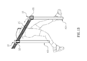
- FIG. 13 is a schematic view illustrating a line divider belt is detached from a magnetic portion of a reel assembly when received sufficient pressure thereon.
- FIG. 14 is a prior art.
- the present invention provides a magnetic retractable line divider which comprises at least a reel assembly ( 10 ).
- the reel assembly ( 10 ) has a shell ( 11 ), and a magnetic portion ( 12 ) is installed thereon.
- An elastic line divider belt ( 20 ) is wound on the reel assembly ( 10 ), and a magnetic member ( 21 ) is connected to a lateral end of the line divider belt ( 20 ).
- the line divider belt ( 20 ) is configured to be horizontally pulled out from the reel assembly ( 10 ) and travel a preferred distance to attach to a magnetic object, thus achieving line divider effect.
- the magnetic member ( 21 ) when someone pushes against the line divider belt ( 20 ) with or over a preferred force, the magnetic member ( 21 ) is configured to be detached from the magnetic object and automatically retracted into the reel assembly ( 10 ), thus avoiding accident. Furthermore, an upper locating disk ( 13 ) and a lower locating disk ( 14 ) are respectively located inside the shell ( 11 ) of the reel assembly ( 10 ), and a spindle ( 15 ) configured to be wound by the line divider belt ( 20 ) is pivotally connected between the upper locating disk ( 13 ) and the lower locating disk ( 14 ).
- a clock spring ( 16 ) is positioned in the lower locating disk ( 14 ), and two ends of the clock spring ( 16 ) respectively bear against a bottom portion of the spindle ( 15 ) and an inner lower surface of the lower locating disk ( 14 ).
- the clock spring ( 16 ) compressed or extended between the spindle ( 15 ) and the lower locating disk ( 14 ) is configured to provide an elastic force to retract or extend the line divider belt ( 20 ).
- the shell ( 11 ) comprises at least a slot ( 111 ) which is configured to be passed through by the line divider belt ( 20 ).
- the shell ( 11 ) of the reel assembly ( 10 ) has an engaging base ( 17 ) mounted thereon.
- the magnetic portion ( 12 ) comprises at least a connecting unit ( 120 ), and the connecting unit ( 120 ) further has a locating piece ( 121 ) which is configured to engage with the engaging base ( 17 ).
- the connecting unit ( 120 ) has a magnetic piece ( 123 ), and a line divider section ( 122 ) is connected between the magnetic piece ( 123 ) and a lateral edge of the locating piece ( 121 ) (as shown in FIGS. 1 to 3 ).
- a user can pull the line divider belt ( 20 ) out from the reel assembly ( 10 ) and attach the magnetic member ( 21 ) to the magnetic piece ( 123 ) of the conning unit ( 120 ) on another reel assembly ( 10 ), thus building a line divider (as shown in FIG. 4 ).
- a rotatable cover ( 18 ) is installed on the reel assembly ( 10 ). Wherein the cover ( 18 ) has at least two convex portions ( 181 ) and at least two concave portions ( 182 ) arranged alternatively around an outer periphery thereof.
- the cover ( 18 ) is configured to be turned to allow the either of the convex portions ( 181 ) to align with the connecting unit ( 120 ), thereby preventing the connecting unit ( 120 ) from been removed from the engaging base ( 17 ).
- the connecting unit ( 120 ) is configured to be allowed to disengage with the engaging base ( 17 ) when aligned with either of the concave portions ( 182 ) of the cover ( 18 ).
- a locating unit ( 19 ) installed between the cover ( 18 ) and the upper locating disk ( 13 ) is configured to position the cover ( 18 ) after each turn.
- the magnetic portion ( 12 ) is a plurality of metal pieces evenly formed on the shell ( 11 ) of the reel assembly ( 10 ) (as shown in FIG. 5 ).
- the magnetic portion ( 12 ) is a plurality of magnets evenly formed on the shell ( 11 ) of the reel assembly ( 10 ) (as shown in FIG. 5 ).
- the magnetic portion ( 12 ) is a piece of metal sheet attached on the shell ( 11 ) of the reel assembly ( 10 ) (as shown in FIG. 6 ).
- the magnetic member ( 21 ) is a magnet.
- the reel assembly ( 10 ) is secured on a wall ( 30 ) located adjacent to an entrance or access, and a magnetic unit ( 31 ) is embedded in another wall ( 30 ) located at an opposite side of the first wall ( 30 ) (as shown in FIG. 7 ).
- the line divider belt ( 20 ) is configured to attach on the wall ( 30 ) having the magnetic unit ( 31 ) through magnetic force, thus building a line divider for the entrance or assess.
- the magnetic unit ( 31 ) is a metal piece or a magnet.
- the two reel assemblies ( 10 ) are respectively secured on the two walls ( 30 ) located at both lateral sides of an entrance, and the line divider belt ( 20 ) received in one of the two reel assemblies ( 10 ) is configured to be pulled out and attached to the magnetic portion ( 12 ) of another reel assembly ( 10 ), thus achieving the line divider effect (as shown in FIGS. 8 and 9 ).
- the two reel assemblies ( 10 ) are respectively secured on the walls ( 30 ) located at both lateral sides of an entrance, and the two line divider belts ( 20 ) are respectively pulled out from of the two reel assemblies ( 10 ) and attached with each other through the two magnetic members ( 21 ), thus increasing the length of line divider.
- At least two reel assemblies ( 10 ) are respectively secured on the wall ( 30 ) and at least a free-standing vertical post ( 40 ), and an entrance is formed between the wall ( 30 ) and the vertical post ( 40 ) (as shown in FIG. 10 ).
- At least two reel assemblies ( 10 ) are respectively secured on two separated vertical posts ( 40 ), and an entrance is formed between the two vertical posts ( 40 ) (as shown in FIG. 11 ).
- At least two reel assemblies ( 10 ) are respectively secured on two separated vertical posts ( 40 ), and the two line divider belts ( 20 ) are respectively pulled out from the two reel assemblies ( 10 ) and attached with each other through the two magnetic members ( 21 ) such that a wider entrance is formed between the two vertical posts ( 40 ) (as shown in FIG. 12 ).
- the vertical post ( 40 ) is secured on the floor.
- the present invention is advantageous because: (i) the line divider belt ( 20 ) of one reel assembly ( 10 ) is configured to attach to the magnetic portion ( 12 ) of another reel assembly ( 10 ), the magnetic member ( 21 ) of the line divider belt ( 20 ) of another reel assembly ( 10 ) or the magnetic unit ( 31 ) of the walls ( 30 ) through magnetic force, instead of the engagement, so that the line divider belt ( 20 ) is configured to detach from these said objects when received over a preferred force and retracted into the reel assembly ( 10 ) (as shown in FIG. 13 ).
- the line divider belt ( 20 ) of one reel assembly ( 10 ) is configured to attach to the magnetic portion ( 12 ) of another reel assembly ( 10 ), the magnetic member ( 21 ) of the line divider belt ( 20 ) of another reel assembly ( 10 ) or the magnetic unit ( 31 ) of the walls ( 30 ) through magnetic force, instead of the engagement, so that the line divider belt ( 20 ) is configured to detach from these said
Abstract
Description
Claims (6)
Priority Applications (1)
| Application Number | Priority Date | Filing Date | Title |
|---|---|---|---|
| US15/387,352 US10035677B2 (en) | 2016-12-21 | 2016-12-21 | Magnetic retractable line divider |
Applications Claiming Priority (1)
| Application Number | Priority Date | Filing Date | Title |
|---|---|---|---|
| US15/387,352 US10035677B2 (en) | 2016-12-21 | 2016-12-21 | Magnetic retractable line divider |
Publications (2)
| Publication Number | Publication Date |
|---|---|
| US20180170709A1 US20180170709A1 (en) | 2018-06-21 |
| US10035677B2 true US10035677B2 (en) | 2018-07-31 |
Family
ID=62556751
Family Applications (1)
| Application Number | Title | Priority Date | Filing Date |
|---|---|---|---|
| US15/387,352 Active US10035677B2 (en) | 2016-12-21 | 2016-12-21 | Magnetic retractable line divider |
Country Status (1)
| Country | Link |
|---|---|
| US (1) | US10035677B2 (en) |
Cited By (6)
| Publication number | Priority date | Publication date | Assignee | Title |
|---|---|---|---|---|
| US20190259315A1 (en) * | 2018-02-20 | 2019-08-22 | Fallswood Llc | System and Method for a Retractable Reel Safety Flags on a Strap |
| US10435855B1 (en) | 2019-07-13 | 2019-10-08 | Andrew Baxter Cohen | Magnetic stanchion connector assembly |
| USD894719S1 (en) * | 2018-07-19 | 2020-09-01 | Adam Mills | Multi-position wall mounted barrier |
| US20210068576A1 (en) * | 2016-11-03 | 2021-03-11 | Philip DiTrolio | Vertical pipe end connector |
| US11008774B2 (en) * | 2019-09-30 | 2021-05-18 | Hefei Wisdom Bridge Information Technology Co., Lt | Fence system |
| USD939923S1 (en) | 2019-02-14 | 2022-01-04 | Laureen Meroueh | Combined C-clip and locking cap for belt barrier |
Families Citing this family (6)
| Publication number | Priority date | Publication date | Assignee | Title |
|---|---|---|---|---|
| EP2937463B1 (en) * | 2014-04-23 | 2017-01-11 | Qmetrix GmbH | Belt stand for a person guidance system |
| US10943189B2 (en) * | 2019-01-24 | 2021-03-09 | Thomas Callahan | System and method for reserving and renting seating |
| DE102019208055A1 (en) * | 2019-06-03 | 2020-07-16 | Audi Ag | Shut-off arrangement |
| CN110629702A (en) * | 2019-09-30 | 2019-12-31 | 宫闻远 | Warning device is used in town road construction |
| GB2595514A (en) * | 2020-05-29 | 2021-12-01 | Tensator Group Ltd | A sign kit for mounting on top of a barrier post |
| CN114162160A (en) * | 2022-01-19 | 2022-03-11 | 西安佳诚标识有限公司 | Wall-mounted magnet type safety isolation device |
Citations (15)
| Publication number | Priority date | Publication date | Assignee | Title |
|---|---|---|---|---|
| US4858551A (en) * | 1988-03-03 | 1989-08-22 | Peters William H | Portable and reusable safety marker for disabled vehicles |
| US6375164B1 (en) * | 1999-06-18 | 2002-04-23 | Lawrence Metal Products , Inc. | Double-tape pedestrian traffic control device and method of assembling it |
| FR2816338A1 (en) * | 2000-11-06 | 2002-05-10 | Jean Jacques Meyer | Post for use in public buildings comprises vertical tube and upper section which carries chains or belts, which form a barrier to guide queues, or notices and has tenon which fits into sleeve mounted on post. |
| US20050023403A1 (en) * | 2003-07-30 | 2005-02-03 | Jin-Chu Lu | Strap supporting post capable of automatically winding a strap around it |
| US20050191107A1 (en) * | 2004-03-01 | 2005-09-01 | Martin Stuart Christie | Tape cartridge with speed restricting mechanism |
| US20050220537A1 (en) * | 2002-03-28 | 2005-10-06 | Alan Bentley | Temporary traffic barrier and method of provision thereof |
| US20070295851A1 (en) * | 2006-06-21 | 2007-12-27 | Dl'manufacturing | Recoil speed control |
| US7909310B2 (en) * | 2007-11-19 | 2011-03-22 | Weiner Steven L | Portable barrier apparatus |
| US8118250B1 (en) * | 2008-04-07 | 2012-02-21 | Andrew Helseth | Fuel tanker truck accessory and associated methods |
| US20140014760A1 (en) * | 2012-07-10 | 2014-01-16 | Robert Tsai | Slowing device for slowing scrolling speed of belt of barrier pole |
| US20150218848A1 (en) * | 2014-02-04 | 2015-08-06 | Steven L. Weiner | Barrier apparatus and methods of use |
| US9175450B2 (en) * | 2013-11-21 | 2015-11-03 | Steven Weiner | Barrier system |
| US20160047953A1 (en) * | 2014-08-18 | 2016-02-18 | Peter James Crawley | Double-sided reflective webbing for pedestrian traffic control devices |
| US20160244923A1 (en) * | 2013-09-23 | 2016-08-25 | Shortcutq Ltd | A queue management gate |
| US20170167093A1 (en) * | 2014-04-23 | 2017-06-15 | Qmetrix Gmbh | Belt Stanchion for a People Guidance System |
-
2016
- 2016-12-21 US US15/387,352 patent/US10035677B2/en active Active
Patent Citations (15)
| Publication number | Priority date | Publication date | Assignee | Title |
|---|---|---|---|---|
| US4858551A (en) * | 1988-03-03 | 1989-08-22 | Peters William H | Portable and reusable safety marker for disabled vehicles |
| US6375164B1 (en) * | 1999-06-18 | 2002-04-23 | Lawrence Metal Products , Inc. | Double-tape pedestrian traffic control device and method of assembling it |
| FR2816338A1 (en) * | 2000-11-06 | 2002-05-10 | Jean Jacques Meyer | Post for use in public buildings comprises vertical tube and upper section which carries chains or belts, which form a barrier to guide queues, or notices and has tenon which fits into sleeve mounted on post. |
| US20050220537A1 (en) * | 2002-03-28 | 2005-10-06 | Alan Bentley | Temporary traffic barrier and method of provision thereof |
| US20050023403A1 (en) * | 2003-07-30 | 2005-02-03 | Jin-Chu Lu | Strap supporting post capable of automatically winding a strap around it |
| US20050191107A1 (en) * | 2004-03-01 | 2005-09-01 | Martin Stuart Christie | Tape cartridge with speed restricting mechanism |
| US20070295851A1 (en) * | 2006-06-21 | 2007-12-27 | Dl'manufacturing | Recoil speed control |
| US7909310B2 (en) * | 2007-11-19 | 2011-03-22 | Weiner Steven L | Portable barrier apparatus |
| US8118250B1 (en) * | 2008-04-07 | 2012-02-21 | Andrew Helseth | Fuel tanker truck accessory and associated methods |
| US20140014760A1 (en) * | 2012-07-10 | 2014-01-16 | Robert Tsai | Slowing device for slowing scrolling speed of belt of barrier pole |
| US20160244923A1 (en) * | 2013-09-23 | 2016-08-25 | Shortcutq Ltd | A queue management gate |
| US9175450B2 (en) * | 2013-11-21 | 2015-11-03 | Steven Weiner | Barrier system |
| US20150218848A1 (en) * | 2014-02-04 | 2015-08-06 | Steven L. Weiner | Barrier apparatus and methods of use |
| US20170167093A1 (en) * | 2014-04-23 | 2017-06-15 | Qmetrix Gmbh | Belt Stanchion for a People Guidance System |
| US20160047953A1 (en) * | 2014-08-18 | 2016-02-18 | Peter James Crawley | Double-sided reflective webbing for pedestrian traffic control devices |
Cited By (7)
| Publication number | Priority date | Publication date | Assignee | Title |
|---|---|---|---|---|
| US20210068576A1 (en) * | 2016-11-03 | 2021-03-11 | Philip DiTrolio | Vertical pipe end connector |
| US20190259315A1 (en) * | 2018-02-20 | 2019-08-22 | Fallswood Llc | System and Method for a Retractable Reel Safety Flags on a Strap |
| US11735074B2 (en) * | 2018-02-20 | 2023-08-22 | Fallswood, LLC | System and method for a retractable reel safety flags on a strap |
| USD894719S1 (en) * | 2018-07-19 | 2020-09-01 | Adam Mills | Multi-position wall mounted barrier |
| USD939923S1 (en) | 2019-02-14 | 2022-01-04 | Laureen Meroueh | Combined C-clip and locking cap for belt barrier |
| US10435855B1 (en) | 2019-07-13 | 2019-10-08 | Andrew Baxter Cohen | Magnetic stanchion connector assembly |
| US11008774B2 (en) * | 2019-09-30 | 2021-05-18 | Hefei Wisdom Bridge Information Technology Co., Lt | Fence system |
Also Published As
| Publication number | Publication date |
|---|---|
| US20180170709A1 (en) | 2018-06-21 |
Similar Documents
| Publication | Publication Date | Title |
|---|---|---|
| US10035677B2 (en) | Magnetic retractable line divider | |
| US10874178B2 (en) | Magnetic buckling assembly | |
| US9717323B2 (en) | Split type hanging buckle | |
| EP3073852B1 (en) | Double-sided wheel assembly and methods thereof | |
| US9988833B2 (en) | Static hinge disabler | |
| US9718640B2 (en) | Retractable badge reel with button display | |
| CN107810032B (en) | D-ring retainer assembly | |
| US20150311938A1 (en) | Security case for a portable electronic device | |
| US9677583B1 (en) | Holder for a seamless control cord of a curtain | |
| EP2645509A1 (en) | Wire winding and unwinding device | |
| US6305197B1 (en) | Cable combination lock | |
| US8979143B1 (en) | Fire bolt assembly for a door | |
| US9907416B1 (en) | Devices for removably mounting an interface device | |
| US8746021B2 (en) | Retractable cable lock assembly for laptop computers | |
| US20060006035A1 (en) | Case with tab protector | |
| US20110197353A1 (en) | Shower curtain lock | |
| CN104239827A (en) | Security strip defining a security slot and attachable to mobile electronic devices | |
| CN107259717A (en) | Hasp | |
| KR101666643B1 (en) | Adverrising balloon with built wireless router | |
| US20170356242A1 (en) | Blind assembly and a winding device thereof | |
| TWM579673U (en) | Lock | |
| TWM545815U (en) | Connection lock | |
| JP2010248793A (en) | Belt partition | |
| CN109488111B (en) | Door lock | |
| US11702254B2 (en) | Locking mechanism for container and lid thereof |
Legal Events
| Date | Code | Title | Description |
|---|---|---|---|
| AS | Assignment |
Owner name: DEPARTMENT OF ELECTRICAL ENGINEERING, NATIONAL CHA Free format text: ASSIGNMENT OF ASSIGNORS INTEREST;ASSIGNORS:CHEN, SHU-MING;LEE, YI-LUNG;CHEN, TSAIR-RONG;AND OTHERS;SIGNING DATES FROM 20161029 TO 20161103;REEL/FRAME:041167/0489 Owner name: TERA AUTOTECH CORPORATION, TAIWAN Free format text: ASSIGNMENT OF ASSIGNORS INTEREST;ASSIGNORS:CHEN, SHU-MING;LEE, YI-LUNG;CHEN, TSAIR-RONG;AND OTHERS;SIGNING DATES FROM 20161029 TO 20161103;REEL/FRAME:041167/0489 |
|
| STCF | Information on status: patent grant |
Free format text: PATENTED CASE |
|
| MAFP | Maintenance fee payment |
Free format text: PAYMENT OF MAINTENANCE FEE, 4TH YR, SMALL ENTITY (ORIGINAL EVENT CODE: M2551); ENTITY STATUS OF PATENT OWNER: SMALL ENTITY Year of fee payment: 4 |