US10034693B2 - Spinous laminar clamp assembly - Google Patents
Spinous laminar clamp assembly Download PDFInfo
- Publication number
- US10034693B2 US10034693B2 US15/643,400 US201715643400A US10034693B2 US 10034693 B2 US10034693 B2 US 10034693B2 US 201715643400 A US201715643400 A US 201715643400A US 10034693 B2 US10034693 B2 US 10034693B2
- Authority
- US
- United States
- Prior art keywords
- hook
- base portion
- cephalad
- spinous
- slot
- Prior art date
- Legal status (The legal status is an assumption and is not a legal conclusion. Google has not performed a legal analysis and makes no representation as to the accuracy of the status listed.)
- Active
Links
- 238000003780 insertion Methods 0.000 claims description 14
- 230000037431 insertion Effects 0.000 claims description 14
- 239000011324 bead Substances 0.000 claims description 5
- 208000004099 Angle Class III Malocclusion Diseases 0.000 claims description 3
- 206010061274 Malocclusion Diseases 0.000 claims description 3
- 230000008878 coupling Effects 0.000 claims description 3
- 238000010168 coupling process Methods 0.000 claims description 3
- 238000005859 coupling reaction Methods 0.000 claims description 3
- 238000013461 design Methods 0.000 abstract description 2
- 230000000087 stabilizing effect Effects 0.000 abstract 1
- 206010017076 Fracture Diseases 0.000 description 20
- 238000000034 method Methods 0.000 description 15
- 208000010392 Bone Fractures Diseases 0.000 description 14
- 230000000712 assembly Effects 0.000 description 6
- 238000000429 assembly Methods 0.000 description 6
- 210000000988 bone and bone Anatomy 0.000 description 6
- 230000004927 fusion Effects 0.000 description 6
- 230000035876 healing Effects 0.000 description 6
- 238000001356 surgical procedure Methods 0.000 description 6
- 210000000115 thoracic cavity Anatomy 0.000 description 5
- 208000027418 Wounds and injury Diseases 0.000 description 4
- 230000008901 benefit Effects 0.000 description 4
- 208000014674 injury Diseases 0.000 description 4
- 230000007170 pathology Effects 0.000 description 4
- 230000006641 stabilisation Effects 0.000 description 4
- 238000011105 stabilization Methods 0.000 description 4
- 206010023204 Joint dislocation Diseases 0.000 description 3
- RTAQQCXQSZGOHL-UHFFFAOYSA-N Titanium Chemical compound [Ti] RTAQQCXQSZGOHL-UHFFFAOYSA-N 0.000 description 3
- 238000013459 approach Methods 0.000 description 3
- 238000010276 construction Methods 0.000 description 3
- 230000006378 damage Effects 0.000 description 3
- 238000003384 imaging method Methods 0.000 description 3
- 208000015181 infectious disease Diseases 0.000 description 3
- 229910052751 metal Inorganic materials 0.000 description 3
- 239000002184 metal Substances 0.000 description 3
- 230000007935 neutral effect Effects 0.000 description 3
- 230000008569 process Effects 0.000 description 3
- 239000010936 titanium Substances 0.000 description 3
- 229910052719 titanium Inorganic materials 0.000 description 3
- 210000002385 vertebral artery Anatomy 0.000 description 3
- 208000032843 Hemorrhage Diseases 0.000 description 2
- 206010041541 Spinal compression fracture Diseases 0.000 description 2
- 239000000560 biocompatible material Substances 0.000 description 2
- 208000034158 bleeding Diseases 0.000 description 2
- 230000000740 bleeding effect Effects 0.000 description 2
- 239000002131 composite material Substances 0.000 description 2
- 238000012937 correction Methods 0.000 description 2
- 125000001475 halogen functional group Chemical group 0.000 description 2
- 239000007943 implant Substances 0.000 description 2
- 239000012528 membrane Substances 0.000 description 2
- 238000012986 modification Methods 0.000 description 2
- 230000004048 modification Effects 0.000 description 2
- 230000002792 vascular Effects 0.000 description 2
- OKTJSMMVPCPJKN-UHFFFAOYSA-N Carbon Chemical compound [C] OKTJSMMVPCPJKN-UHFFFAOYSA-N 0.000 description 1
- 229920000049 Carbon (fiber) Polymers 0.000 description 1
- 208000019505 Deglutition disease Diseases 0.000 description 1
- 206010028980 Neoplasm Diseases 0.000 description 1
- 208000028389 Nerve injury Diseases 0.000 description 1
- 206010058522 Oesophageal injury Diseases 0.000 description 1
- 206010035669 Pneumonia aspiration Diseases 0.000 description 1
- 229910000831 Steel Inorganic materials 0.000 description 1
- 239000000956 alloy Substances 0.000 description 1
- 229910045601 alloy Inorganic materials 0.000 description 1
- 230000004075 alteration Effects 0.000 description 1
- 201000009807 aspiration pneumonia Diseases 0.000 description 1
- 238000005452 bending Methods 0.000 description 1
- 239000008280 blood Substances 0.000 description 1
- 210000004369 blood Anatomy 0.000 description 1
- 230000036770 blood supply Effects 0.000 description 1
- 239000004917 carbon fiber Substances 0.000 description 1
- 230000008859 change Effects 0.000 description 1
- 230000006835 compression Effects 0.000 description 1
- 238000007906 compression Methods 0.000 description 1
- 230000007812 deficiency Effects 0.000 description 1
- 230000001419 dependent effect Effects 0.000 description 1
- 238000005553 drilling Methods 0.000 description 1
- 238000005516 engineering process Methods 0.000 description 1
- 210000003238 esophagus Anatomy 0.000 description 1
- 239000003302 ferromagnetic material Substances 0.000 description 1
- 229910021389 graphene Inorganic materials 0.000 description 1
- 230000001788 irregular Effects 0.000 description 1
- 210000004705 lumbosacral region Anatomy 0.000 description 1
- 230000007246 mechanism Effects 0.000 description 1
- VNWKTOKETHGBQD-UHFFFAOYSA-N methane Chemical compound C VNWKTOKETHGBQD-UHFFFAOYSA-N 0.000 description 1
- 230000001483 mobilizing effect Effects 0.000 description 1
- 210000005036 nerve Anatomy 0.000 description 1
- 230000008764 nerve damage Effects 0.000 description 1
- 239000004033 plastic Substances 0.000 description 1
- 238000004393 prognosis Methods 0.000 description 1
- 230000002035 prolonged effect Effects 0.000 description 1
- 210000003625 skull Anatomy 0.000 description 1
- 210000000278 spinal cord Anatomy 0.000 description 1
- 206010041569 spinal fracture Diseases 0.000 description 1
- 239000010959 steel Substances 0.000 description 1
- 238000006467 substitution reaction Methods 0.000 description 1
- 238000011477 surgical intervention Methods 0.000 description 1
- 229920002994 synthetic fiber Polymers 0.000 description 1
- 210000003437 trachea Anatomy 0.000 description 1
- 230000008733 trauma Effects 0.000 description 1
- 210000003462 vein Anatomy 0.000 description 1
- 238000012800 visualization Methods 0.000 description 1
Images


Classifications
-
- A—HUMAN NECESSITIES
- A61—MEDICAL OR VETERINARY SCIENCE; HYGIENE
- A61B—DIAGNOSIS; SURGERY; IDENTIFICATION
- A61B17/00—Surgical instruments, devices or methods
- A61B17/56—Surgical instruments or methods for treatment of bones or joints; Devices specially adapted therefor
- A61B17/58—Surgical instruments or methods for treatment of bones or joints; Devices specially adapted therefor for osteosynthesis, e.g. bone plates, screws or setting implements
- A61B17/68—Internal fixation devices, including fasteners and spinal fixators, even if a part thereof projects from the skin
- A61B17/70—Spinal positioners or stabilisers, e.g. stabilisers comprising fluid filler in an implant
- A61B17/7056—Hooks with specially-designed bone-contacting part
-
- A—HUMAN NECESSITIES
- A61—MEDICAL OR VETERINARY SCIENCE; HYGIENE
- A61B—DIAGNOSIS; SURGERY; IDENTIFICATION
- A61B17/00—Surgical instruments, devices or methods
- A61B17/56—Surgical instruments or methods for treatment of bones or joints; Devices specially adapted therefor
- A61B17/58—Surgical instruments or methods for treatment of bones or joints; Devices specially adapted therefor for osteosynthesis, e.g. bone plates, screws or setting implements
- A61B17/68—Internal fixation devices, including fasteners and spinal fixators, even if a part thereof projects from the skin
- A61B17/70—Spinal positioners or stabilisers, e.g. stabilisers comprising fluid filler in an implant
- A61B17/7001—Screws or hooks combined with longitudinal elements which do not contact vertebrae
- A61B17/7002—Longitudinal elements, e.g. rods
-
- A—HUMAN NECESSITIES
- A61—MEDICAL OR VETERINARY SCIENCE; HYGIENE
- A61B—DIAGNOSIS; SURGERY; IDENTIFICATION
- A61B17/00—Surgical instruments, devices or methods
- A61B17/56—Surgical instruments or methods for treatment of bones or joints; Devices specially adapted therefor
- A61B17/58—Surgical instruments or methods for treatment of bones or joints; Devices specially adapted therefor for osteosynthesis, e.g. bone plates, screws or setting implements
- A61B17/68—Internal fixation devices, including fasteners and spinal fixators, even if a part thereof projects from the skin
- A61B17/70—Spinal positioners or stabilisers, e.g. stabilisers comprising fluid filler in an implant
- A61B17/7001—Screws or hooks combined with longitudinal elements which do not contact vertebrae
- A61B17/7043—Screws or hooks combined with longitudinal elements which do not contact vertebrae with a longitudinal element fixed to one or more transverse elements which connect multiple screws or hooks
-
- A—HUMAN NECESSITIES
- A61—MEDICAL OR VETERINARY SCIENCE; HYGIENE
- A61B—DIAGNOSIS; SURGERY; IDENTIFICATION
- A61B17/00—Surgical instruments, devices or methods
- A61B17/56—Surgical instruments or methods for treatment of bones or joints; Devices specially adapted therefor
- A61B17/58—Surgical instruments or methods for treatment of bones or joints; Devices specially adapted therefor for osteosynthesis, e.g. bone plates, screws or setting implements
- A61B17/68—Internal fixation devices, including fasteners and spinal fixators, even if a part thereof projects from the skin
- A61B17/70—Spinal positioners or stabilisers, e.g. stabilisers comprising fluid filler in an implant
- A61B17/7047—Clamps comprising opposed elements which grasp one vertebra between them
-
- A—HUMAN NECESSITIES
- A61—MEDICAL OR VETERINARY SCIENCE; HYGIENE
- A61B—DIAGNOSIS; SURGERY; IDENTIFICATION
- A61B17/00—Surgical instruments, devices or methods
- A61B17/56—Surgical instruments or methods for treatment of bones or joints; Devices specially adapted therefor
- A61B17/58—Surgical instruments or methods for treatment of bones or joints; Devices specially adapted therefor for osteosynthesis, e.g. bone plates, screws or setting implements
- A61B17/68—Internal fixation devices, including fasteners and spinal fixators, even if a part thereof projects from the skin
- A61B17/70—Spinal positioners or stabilisers, e.g. stabilisers comprising fluid filler in an implant
- A61B17/7049—Connectors, not bearing on the vertebrae, for linking longitudinal elements together
-
- A—HUMAN NECESSITIES
- A61—MEDICAL OR VETERINARY SCIENCE; HYGIENE
- A61B—DIAGNOSIS; SURGERY; IDENTIFICATION
- A61B17/00—Surgical instruments, devices or methods
- A61B17/56—Surgical instruments or methods for treatment of bones or joints; Devices specially adapted therefor
- A61B17/58—Surgical instruments or methods for treatment of bones or joints; Devices specially adapted therefor for osteosynthesis, e.g. bone plates, screws or setting implements
- A61B17/68—Internal fixation devices, including fasteners and spinal fixators, even if a part thereof projects from the skin
- A61B17/70—Spinal positioners or stabilisers, e.g. stabilisers comprising fluid filler in an implant
- A61B17/7062—Devices acting on, attached to, or simulating the effect of, vertebral processes, vertebral facets or ribs ; Tools for such devices
- A61B17/7065—Devices with changeable shape, e.g. collapsible or having retractable arms to aid implantation; Tools therefor
-
- A—HUMAN NECESSITIES
- A61—MEDICAL OR VETERINARY SCIENCE; HYGIENE
- A61B—DIAGNOSIS; SURGERY; IDENTIFICATION
- A61B17/00—Surgical instruments, devices or methods
- A61B17/56—Surgical instruments or methods for treatment of bones or joints; Devices specially adapted therefor
- A61B17/58—Surgical instruments or methods for treatment of bones or joints; Devices specially adapted therefor for osteosynthesis, e.g. bone plates, screws or setting implements
- A61B17/68—Internal fixation devices, including fasteners and spinal fixators, even if a part thereof projects from the skin
- A61B17/70—Spinal positioners or stabilisers, e.g. stabilisers comprising fluid filler in an implant
- A61B17/7001—Screws or hooks combined with longitudinal elements which do not contact vertebrae
- A61B17/7032—Screws or hooks with U-shaped head or back through which longitudinal rods pass
Definitions
- the present invention pertains generally to devices surgically implanted for spinal stabilization. More specifically, the present invention relates to clamp devices together with an insertion tool for cervical spine fixation in the management of vertebral fractures.
- a sub-specialization herein is the treatment and healing of the Type-II Odontoid Fracture occurring on the dens portion of the cervical spine.
- the odontoid process a.k.a. dens
- the upper cervical (C0-C2) is the most common fracture location in patients 65 years of age and above.
- Type-1 and Type-III Other fractures (e.g. Type-1 and Type-III) specifically involving the C1-C2 vertebrae are also pertinent to devices and methods herein. More particularly, the Type-I Odontoid fracture would occur at the top portion of the dens and is generally stable without the need for surgery.
- the Type-II is the most common of the three and occurs at the base of the dens where it protrudes from the body of the C2.
- the Type-III occurs just below the base of the dens at the thicker vertebral C2 body.
- the Type-III fracture prognosis would call for better healing on thicker, more stable area with better blood supply thereto.
- halo orthosis device that is essentially a head and neck brace that does not require pin-insertion-into-the-spine type surgery to implement. Instead, a metal ring is attached to a patient's skull which is subsequently attached to a vest. But however, the success rate for the halo device is small. This orthosis is poorly tolerated by elderly patients with low yield for fusion and high complication rate of infection, further falls, and other complications.
- a second option is the anterior dens screws that require mobilizing the esophagus and trachea from an anterior approach with a high degree of complication of esophageal injury, swallowing disorder, and aspiration pneumonia. Also, the success rate for drills and screws is small due to poor access, and inadequate stabilization; and it is not tolerated in the age group that experiences most frequently dens fractures.
- Harms pedicle also employing screws, which, in this instance require significant immobilization of vascular and neutral structures of the C1-C2 junction increasing risk of bleeding, nerve injury, damaged veins and perforation of the vertebral artery as the screw enters the bone and possibly displace either medially into the spinal cord or laterally into the vertebral arteries.
- transarticular screws will liking produce excessive bleeding and complications and also initially require a lateral aspect x-ray.
- the present invention introduces a fixation device attaching to the thin laminar plates (lamina) consisting of layers bone membranes.
- an object of the present to provide an autonomous laminar clamp solution; and further specifically provide a three-point or four-point clamp system particular to a vertebral level with a second set of three-point or four-point clamps offset.
- Angular offset approach to the specific laminae can be achieved by rotating clamps and/or a single clamp system may be employed, or as further detailed here.
- the present invention seeks to provide solutions applicable to the cervical 1 to the cervical 7 , from thoracic 1 to thoracic 12 , and from lumbar 1 to lumbar 5 . Yet further, it is an object of the present invention to provide a solution addressing vertebral malalignment and frank subluxation. Still further, it is an object of the present invention to provide a solution with all components with biocompatible material to the vertebrae, providing strength and longevity until fusion and healing occurs. It is still further an object to provide alternative approaches depending on type and location of fracture and therefore pathology dependent.
- an object of the present invention to provide a device the can be easily removed, if necessary, at a later date should complications arise such as infection, or complication requiring additional surgery. It is yet still further an object of the present invention to provide a clamp system appropriate for affixing to complex geometries and irregular surfaces.
- the present invention specifically addresses and alleviates the above mentioned deficiencies, more specifically, the present invention, in a first aspect, is a spinous laminar clamp for fixating and unitizing a human spine comprising: a first base portion providing structural integrity thereto; and a first slot through a top and a bottom of the first base portion for receiving a first lower caudal hook, wherein the first lower caudal hook is slidingly adjustable vertically via the first slot.
- the invention in this first aspect is additionally characterized in that an upper cephalad hook is configured to the first base portion, the upper cephalad hook and the lower caudal hook together for tightening to a vertebral surface (for example, a laminar surface) for fixating and unitizing the human spine.
- the invention in the first aspect is additionally characterized wherein the first slot is through the top and the bottom of the first base portion and it further comprises an opening to a rear of the first base portion, the opening providing a “U” channel in the top aspect, the opening configured to slidingly receive a stem of the first lower caudal hook in its upright position thereby providing for a rear loading of the first caudal hook, further thereby the stem of the first lower caudal hook is able to slide laterally in its upright position for surgical placement and subsequently can slide up and down in its upright position via the first slot.
- the opening further comprises threads; and the threads are configured to receive a tightening screw through the rear of the first base portion for contacting the stem of the first lower caudal hook. Still further, the threads are configured partially hemispherically through opposing walls of the first slot.
- the spinous laminar clamp for fixating and unitizing vertebrae in this aspect is additionally characterized in that the tightening screw comprises a bead at an end thereof for optimally contacting and securing the stem of the first lower caudal hook.
- the first lower caudal hook comprises a stem, the stem being cylindrical in shape, the cylindrical shape providing rotation of the stem within the first slot, the rotation for aligning to a complex geometry of the vertebral surface.
- the invention in this aspect is further characterized as comprising: a second base portion in a common horizontal plane with said first base portion; and a second slot through a top and a bottom of the second base portion for receiving a second lower caudal hook, wherein the second lower caudal hook together with the first cephalad hook and first lower caudal hook are for fixating and unitizing a human spine, wherein thereby the first and the second caudal hooks together with the first cephalad hook provide a three-point fixation to the spine, the three-point fixation being particular to a single vertebral level.
- the spinous laminar clamp herein further comprises a bridge connecting the first and second base portions, the bridge being an isthmus between the first and the second base portions, wherein the bridge comprises said first cephalad hook at a center thereof, thereby the first cephalad hook is configured to the first base portion via said bridge, wherein the first and second base portions together form a first collective base on the common horizontal plane providing structural integrity to the spinous laminar clamp.
- the first aspect is characterized as comprising: an arm extending forward from the bridge, the arm having a curved portion at an end thereof; and a spike configured to the curved portion for fixedly contacting the vertebral surface.
- Yet another third slot is also provided through a top and a bottom of the first base portion for receiving a first connecting rod, the third slot at an outer portion of the first base portion with respect to the first slot, wherein the first connecting rod is configured to a third base portion.
- the third base portion has fixation at a vertebral level directly above or below (subjacent) a vertebral level of the first and second base portion, thereby providing fixation at two vertebral levels.
- the invention may be characterized as spinous laminar clamp comprising: a first base portion providing structural integrity thereto; a first aperture through a top and a bottom of the first base portion for slidingly receiving an upper cephalad hook; and a fixed lower jaw coupled to the first base portion opposite the cephalad hook, the cephalad hook and the lower jaw together for tightening to a vertebral surface (for example, a laminar surface).
- a vertebral surface for example, a laminar surface
- the invention may be characterized wherein the fixed lower jaw comprises a hole therethrough to receive the cephalad hook stem.
- the spinous laminar clamp further comprises a threaded aperture through a side of the first base portion configured with a tightening screw for tightening to the cephalad hook stem via the threaded aperture.
- the lower jaw further comprises a spike for fixating and unitizing, further wherein the lower jaw and the cephalad hook together form an underbite (when in lowest position but also when not in use) thereby wherein the lower jaw protrudes slightly farther than the upper hook.
- the invention may be characterized as comprising: a second base portion in a same horizontal plane with said first base portion; a second fixed lower jaw configured at an underside of the second base portion; and a second aperture through a top and a bottom of the second base portion for receiving a second cephalad hook.
- the second fixed lower jaw together with the first cephalad hook and first fixed lower jaw are for fixating and unitizing a human spine. Additionally thereby, the first and second cephalad hook together with the first and second fixed lower jaw provide a four-point fixation to the spine, four-point fixation being particular to a single vertebral level.
- the invention is characterized as having an isthmus connecting the first and second base portion, the isthmus providing an approximately 90 degree offset with respect to the first and second base portions thereby providing the offset to the first and second cephalad hooks.
- the invention may be characterized as a spinous laminar clamp assembly providing fixation at multiple vertebral levels comprising a first base portion configured to a first hook with a first stem slidingly received by the first base portion; a second base portion configured to a second hook with a second stem slidingly received by the second base portion, the second base portion in a first shared horizontal plane to the first base portion; a first isthmus between the first and the second base portion, the first isthmus having a third hook, wherein the first hook, second hook and third hook provide a three-point fixation to a first vertebral level; a third and a fourth base portion configured subjacent (below) said first and said second base portions, the third and fourth base portion in a second horizontal plane further fixated to a second vertebral level; and a connecting rod coupling the first and second base portions to the third and the fourth base portions, the first, the second, the third and the fourth base portions together with the connecting rod providing fixation at the multiple vertebral levels.
- the spinous laminar clamp assembly in the third aspect is additionally characterized as further comprising an insertion instrument having an upper and a lower jaw at a distal end for grasping and tightening the first hook and the second hook to a vertebral surface.
- the first, the second, the third, and the fourth base portions each further comprise a slot through a top and a bottom.
- Each slot is U-shaped in a top aspect wherein a pair of opposing side walls of the slot are threaded, forming a threaded side channel out of a rear of each of the first, the second, and the third base portions for tightening and securing the connecting rod which is a vertical connecting rod for connecting the multiple levels.
- FIG. 1A and FIG. 1B illustrate perspective views of an exemplary human spine
- FIG. 2A is a partially assembled, partially exploded view of a first preferred lamina fixation device of the present invention
- FIG. 2B is an isometric view of the device positioned and in use
- FIG. 2C is an enlarged view thereof
- FIG. 2D is still further an enlarged view at a single vertebral level and an exemplary insertion device
- FIG. 2E a cross-sectional view taken along line 2 E- 2 E in FIG. 2D ;
- FIG. 2F is still further an enlarged view at a single vertebral level showing the device being cinched down on a laminar surface;
- FIG. 2G an cross-sectional view taken along line 2 G- 2 G in FIG. 2F ;
- FIG. 3A is an additional enlarged isometric view of the first preferred device from a forward vantage point
- FIG. 3B is an additional exploded view of the first preferred device in the reverse position as compared to FIG. 3A ;
- FIG. 3C is a perspective view of a singular base portion
- FIG. 4A is a rear isometric view of the preferred device with the cephalad hooks removed revealing their apertures;
- FIG. 4B is a top plan view thereof
- FIG. 4C is an elevational view thereof
- FIG. 4D is a forward isometric view of same
- FIG. 4E , FIG. 4F and FIG. 4G illustrate various views of a cephalad hook configured to the present invention
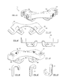
- FIG. 5A is a perspective view of yet a second preferred embodiment of the present invention with a unique combination of fixed and/or adjustable hooks however comparable to the first preferred embodiment;
- FIG. 5B is an elevational view of the second embodiment in a preferred position
- FIG. 5C is an isometric view of a single vertebral level of the second preferred clamp assembly from a side vantage point;
- FIG. 5D is a profile view thereof
- FIG. 5E is an elevational view thereof
- FIG. 5F is a top plan view of the second preferred device
- FIG. 5G is a cross-sectional view of the second preferred embodiment taken along sectional line 5 G- 5 G in FIG. 5D .
- FIG. 6A is a perspective view of yet a third preferred embodiment identical to the second preferred embodiment in most respects;
- FIG. 6B is an elevation view thereof.
- FIG. 6C is finally a top plan view thereof.
- FIG. 1A and FIG. 1B a human spine 99 is shown in perspective views. Again, by way of background, an upper area of the cervical spine 99 is emphasized at the (C1) 91 and the (C2) 92 levels.
- a Type II fracture will occur at the base of the dens 93 , a.k.a. odontoid process.
- a Type III fracture occurs just below the base of the dens 93 at the thicker area 94 .
- the posterior laminar surface 95 is relatively better suited for spinal fixation as compared to lateral portions of the spine due to healing properties following surgery and reduced blood loss during the surgical implant procedure. Its 95 unique structure is also better suited for stabilization comprising bone membrane in layers ultimately forming a thing plate providing some space for access.
- the basic components of the spinal laminar clamp assemblies 10 , 50 , 70 are not only intended for cervical levels (C1) to (C7) of the spine, but are further adaptable to all levels, including the lumbar and thoracic regions of the spine.
- the clamp assemblies 10 , 50 , 70 and combinations thereof can be adaptable to all areas of the spine. It should be noted that applicable surgical techniques may be slightly varied for pathology and fracture area.
- a first preferred partially assembled spinous laminar clamp assembly has two laminar clamp base portions 12 , 13 ( FIG. 3A ), that are side by side. An additional set of base portions 12 , 13 are set below subjacent to secure two cervical levels 91 , 92 . Also with regard to FIG. 2B and FIG. 2C , vertical rods 41 connect the base portions 12 , 13 each at multiple levels. The two base portions 12 , 13 at the same level form a collective base 11 connected by an isthmus 14 that provides a 90 degrees offset. Further the clamps connect at a posterior of the vertebrae at the left and right lamina 95 . FIG.
- FIG. 2B provides an isometric view of the first preferred embodiment 10 positioned and in use; meanwhile FIG. 2C provide an enlarged view of the spinous laminar clamp assembly 10 providing grasping, tightening, fixating and unitizing a spine.
- the basic components of the invention are the base portions 12 , 13 , 52 , 53 that form collective bases 11 , 51 or vertebral units and their associated hooks/fixed jaws 21 , 31 , 59 , 61 , 65 for fixation, fusion fracture healing, and/or correction of deformity, correction of previously performed surgery, misalignment due to injury, posture, or genetics, tumors, and subluxations.
- FIG. 2D provides an additional enlarged view of the first preferred embodiment 10 at a single vertebral level 91 to include an exemplary insertion device 81 .
- the insertion instrument 81 may be in the form of thongs, elongated forceps, or cinching and clamping jaws that enclose from above and below as clearly shown in FIG. 2E , FIG. 2F , and FIG. 2G .
- the invention in another aspect is a spinous laminar clamp assembly 10 having two sets of two base portions 12 , 13 .
- a spinal fixation system 10 that includes an insertion instrument 81 .
- an insertion instrument 81 is provided for cinching down on each hook 21 and jaw 31 combination.
- the insertion instrument 81 further comprises opposing arms connected in a center by a scissor joint coupling and providing relative movement of each arm.
- the insertion instrument also has similar construction and mechanical advantage as pliers or forceps.
- an elongated Allen wrench type tool with a tee handle at a proximal end thereof for tightening the torque screw 22 and the locking screw 42 .
- the upper and lower clamp assemblies 11 are positioned; and then they are serially pinched with the insertion instrument 81 , further successive torque screws 22 are tightened; and the locking screws 42 are tightened for fixing and unitizing.
- insertion instrument can be ratcheted or measured shut to gradually, carefully and reversibly close hooks 21 , 31 , 59 , 61 , 65 in all embodiments 10 , 50 70 contemplated herein.
- the clamping mechanism can be loosened, if necessary, for further placement if there is malalignment or need for removal for various events such as infection.
- FIG. 2G best illustrates the fixation with the lower jaw spike 34 and upper hook 21 portion connecting around the caudal lamina 95 . Additionally with regard to FIG. 2G , the lower jaw 31 and the cephalad hook 21 together form an underbite (when in lowest position but also when not in use) thereby wherein the lower jaw 31 protrudes slightly farther than the upper hook 21 .
- FIG. 3A provides an additional enlarged isometric view of the laminar clamp 10 from a forward vantage point.
- first and second base portions 12 , 13 are offset by approximately 90 degrees.
- Each 12 , 13 has an aperture 15 through a top and a bottom for slidingly receiving an upper cephalad hook 21 that forms an upper part of each clamp 10 collective base portion 11 .
- a fixed lower jaw 31 coupled to each base portion 12 , 13 at the base opposite the cephalad hook. Additionally, the cephalad hook 21 and the lower jaw 31 are tightened together and to the lamina 95 .
- the fixed lower jaw 31 is at the caudal aspect.
- a torque screw 22 is provided for securing hooks; and further a bead 23 ( FIG.
- a spike 34 is provided to various embodiments assisting locking to the layered lamina surface 95 .
- spike 34 could be configured to any of hooks 21 , 31 , 59 , 61 as further detailed herein.
- a locking screw 42 is provided for tightening the vertical rods 41 as further detailed herein.
- each base portion 12 , 13 has a U channel 17 (or slot 17 ) therethrough at a rear end thereof 12 , 13 having threads along the sides of the U channel 17 .
- the slot 17 is further rounded at the bottom of the U (in the top aspect) for receiving the vertical rods 41 for connecting at multiple levels 91 , 92 .
- Isthmus 14 comprises a thinner area 14 connecting wider masses 12 , 13 form a composite base 11 and provides an approximate ninety degree offset to provide an offset angle with which to engage the lamina 95 .
- the invention is a spinous laminar clamp base portion 12 (as shown in FIG. 3C ) comprising a first base portion 12 providing structural integrity to the laminar clamp 10 .
- a first aperture 15 is configured through a top and a bottom of the base portion 12 for slidingly receiving an upper cephalad hook 21 .
- a lower jaw 31 is fixed to the base 12 opposite the cephalad hook 21 , the cephalad hook 21 and the lower jaw 31 together clamp down on the laminar 95 surface.
- the clamp assemblies 10 , 11 , 50 , 51 , 70 are made from surgical grade titanium, non-ferromagnetic material, for allowing imaging after implant.
- components 11 , 21 , 31 , 41 , 51 , 59 , 61 , 65 are made from biocompatible materials including titanium, plastic, steel, or composite material such as carbon fiber, graphene, or synthetic material.
- the titanium or alloy will be chosen to allow slight flexing at the vertical rods 41 to correct malalignment and frank subluxation. Malalignments are particularly deformities cause by injury, posture or genetics, for example.
- the clamps upper 21 , 59 and lower 31 , 61 jaws allow for slight flexing to adjust to various shapes of the lamina 95 .
- FIG. 4A through 4D provide various views of a pair of clamps connected by the center isthmus 14 with the cephalad hooks 21 removed revealing their apertures 15 .
- the fixed lower jaw 31 of each base portion 12 , 13 has an aperture 33 therethrough for receiving the cephalad hook 21 as it is tightened and clamped.
- the lower jaw 31 further has a spike 34 configured thereto.
- FIG. 4E , FIG. 4F and FIG. 4G illustrate various view of a cephalad hook 21 configured having a stem portion and a hook portion, the hook portion in the form of a “J” as shown.
- a second preferred embodiment 50 is illustrated in an isometric view and an elevational view, respectively.
- each 50 , 10 may be referred to as three and four-point fixation, respectively.
- an aggregate of embodiments 10 , 50 , 70 include multiple options for combining fixed and adjustable hooks 21 , 31 , 59 , 61 for each embodiment 10 , 50 .
- various embodiments 10 , 50 , 70 herein may in fact be inverted, so the cephalad and caudal aspect may be flipped upside down. This may also depend on the amount of disruption of the cephalad laminar 95 or any of various pathologies.
- the illustrated invention is a spinous laminar clamp 50 for fixating and unitizing a human spine 99 comprising: a first base portion 52 , and a first aperture 55 through a top and a bottom of the first base portion 52 for receiving a first lower caudal hook 61 .
- FIG. 5E particularly illustrates where the first lower caudal hook 61 is adjustable vertically via the first aperture 55 . In other words, it 61 is able to slide up and down, for vertical adjustment.
- the two base portions 52 , 53 at the same vertebral level 51 form a collective base 51 connected by a bridge 54 , or isthmus.
- the lower caudal hook 61 can rotate ( FIG. 5C ) about its vertical axis, or its stem, for optimally engaging a laminar surface 95 that may vary in size or orientation because of its inherent complex geometry.
- the cylindrical shape of the hook 61 stem and its aperture 55 provide for the rotation.
- a single upper cephalad hook 59 is configured to the first base portion 52 , broadly and generally speaking.
- the cephalad hook 59 is more specifically configured to the first base portion 52 and the second base portion 53 via a bridge 54 connecting the first 52 and second 53 base portions, at a center thereof 54 .
- the bridge 54 has an arm that extends forward ( FIG. 5D , for example, arm extends forward with a hook 59 at an end thereof).
- the arm and hook 59 together with hooks 61 are provided for tightening and clamping to either side of a vertebral surface at a desired level, for example the (C2) 92 .
- first and second caudal hooks 61 together with the first cephalad hook 59 provide a three-point fixation to the spine, the three-point fixation being particular to a single vertebral level.
- spike 34 can be configured to cephalad hook 59 , or caudal hooks 61 , as desired by the particular application.
- aperture 55 aligned vertically, connects to a threaded aperture 56 aligned horizontally through a rear of first 51 and second 52 base portions.
- FIG. 5G specifically illustrates how a side of vertical aperture 55 connects to a side of horizontal aperture 56 .
- Tightening screw 62 is provided to secure the hook 61 stem vertically and rotationally. Different than other embodiments 10 , 70 , tightening screw 62 will secure to a side of the screw against hook 61 ; hence contact bead 23 will not be applicable to this example 50 .
- FIG. 6A through FIG. 6C An additional embodiment 70 is illustrated in FIG. 6A through FIG. 6C .
- horizontal aperture 56 is replaced with the slot 76 as in previous embodiments 10 , 50 having slots 17 , 57 for connecting rods 41 .
- the invention in this aspect 70 comprises a first slot 76 through the top and the bottom of the first base portion 52 further comprising an opening to a rear of the first base portion 52 (the opening providing a “U” channel in the top aspect ( FIG. 6C , for example, or FIG. 4A and FIG. 4B , U channel 17 ), the opening configured to slidingly receive a stem of the first lower caudal hook 61 in its upright position.
- the caudal hook 61 may be inserted from the rear instead of up from underneath as with aperture 55 .
- hook 61 can be attached inferiorly or caudally without having to insert from underneath. It is additionally contemplated herein, that hook 61 may be attached inferiorly by being dropped down from above through slot 76 if the hooking portion of hook 61 were made small enough to fit through slot 76 .
- Threads are configured to the slot 76 and are just like slots 17 , 57 , to receive a tightening screw 62 through the rear of the first base portion 51 (and similarly second base portion 52 ) for contacting the stem of the first lower caudal hook 61 . Similar to previous embodiments 10 , 50 the threads 58 are further configured partially hemispherically through opposing walls of the first slot 76 .
- a third slot 57 through a top and a bottom of the first base portion 52 is for receiving a first connecting rod 41 .
- the third slot 57 is positioned at an outer portion of the first base portion 52 with respect to the first slot 76 , or first aperture 55 .
- the first connecting rod 41 is configured to a third base portion (for example third base portion is one half of collective base portion 51 at the lower level in FIG. 5B ).
- the third base portion further provides fixation at a vertebral level directly above or below a vertebral level of the first and second base portion 52 , 53 , (also termed collective base portions 51 ); and thereby providing fixation at two vertebral levels.
- contact bead 23 may be added to tightening screw 62 for optimally contacting to hook 61 stem. Also in this embodiment 70 , a hook with shorter 65 or longer 61 vertical stems are provided depending on the application.
- the invention can easily fixate all cervical levels minimizing risk to neutral and vascular structures and can be accomplished with direct visualization and without a need for specific radiographic imaging.
- Device imaging can be facilitated with markings on the device if it is not metal. If it is metal, it can be clearly seen.
- the clamp assemblies 10 , 50 , 70 as they sit, do not require any drilling into the bone laterally near the vertebral arteries or near any nerve roots or near the spinal canal as it sits posteriorly on the lamina 95 away from neutral components. It 10 , 50 70 requires smaller incisions and the insertion device retreats directly out of the wound and can be angled off to the side as to be held out of the field of view.
- each embodiment 10 , 50 , 70 provides ability to be bent and/or shaped by bending a component so it fits more proximally to the bone 99 without taking up superfluous space.
Landscapes
- Health & Medical Sciences (AREA)
- Orthopedic Medicine & Surgery (AREA)
- Life Sciences & Earth Sciences (AREA)
- Neurology (AREA)
- Surgery (AREA)
- Heart & Thoracic Surgery (AREA)
- Engineering & Computer Science (AREA)
- Biomedical Technology (AREA)
- Nuclear Medicine, Radiotherapy & Molecular Imaging (AREA)
- Medical Informatics (AREA)
- Molecular Biology (AREA)
- Animal Behavior & Ethology (AREA)
- General Health & Medical Sciences (AREA)
- Public Health (AREA)
- Veterinary Medicine (AREA)
- Surgical Instruments (AREA)
- Prostheses (AREA)
Abstract
A spinous laminar clamp system is disclosed herein. The preferred embodiments are either a three or a four-point fixation system at a particular vertebral level. For example, a two-point adjustable fixation below a vertebrae and a single-point non-adjustable point above the vertebrae exemplifies the three-point fixation. Multiple level and further stabilizing is provided by fixation to subjacent vertebrae above and/or below with a connecting rod providing unitization between levels. Specific designs are applicable to the cervical spine; however, fixation at all levels and regions of the human spine are contemplated.
Description
This patent application claims benefit of the priority date of U.S. Prov. Pat. App. Ser. No. 62/359,424 filed on Jul. 7, 2016 entitled “Spinous Laminar Clamp System and Method of Insertion.” Accordingly, the entire contents this U.S. provisional patent submission is hereby expressly incorporated by reference.
The present invention pertains generally to devices surgically implanted for spinal stabilization. More specifically, the present invention relates to clamp devices together with an insertion tool for cervical spine fixation in the management of vertebral fractures.
Systems and methods for spinal stabilization and fixation particularly to treat fractures thereof have been introduced heretofore. A sub-specialization herein is the treatment and healing of the Type-II Odontoid Fracture occurring on the dens portion of the cervical spine. With regard to FIG. 1A and FIG. 1B , the odontoid process, a.k.a. dens, is a peg-like protrusion shown on the uppermost part of the spine corresponding to the C2 vertebrae. This type of injury is very common in accidents involving elderly population wherein the upper cervical (C0-C2) is the most common fracture location in patients 65 years of age and above. In addition to trauma event, elderly persons are particularly susceptible to falling with an extension event, hitting of the head against a cupboard, sink or wall causing fracturing at the base of the dens. The frequent occurrence of this fracture has increased recently as people live longer reaching an age where falls are more common.
Other fractures (e.g. Type-1 and Type-III) specifically involving the C1-C2 vertebrae are also pertinent to devices and methods herein. More particularly, the Type-I Odontoid fracture would occur at the top portion of the dens and is generally stable without the need for surgery. The Type-II, as stated, is the most common of the three and occurs at the base of the dens where it protrudes from the body of the C2. The Type-III occurs just below the base of the dens at the thicker vertebral C2 body. The Type-III fracture prognosis would call for better healing on thicker, more stable area with better blood supply thereto.
There remains some debate as to the proper management or Type II fractures, particularly in the elderly wherein prolonged cervical immobilization is weighed against the risks of surgical intervention. These patients have a high degree of failure of fusion and proper bone healing. And, existing technologies have a significant morbidity and mortality. More specifically, a least invasive alternative is the halo orthosis device that is essentially a head and neck brace that does not require pin-insertion-into-the-spine type surgery to implement. Instead, a metal ring is attached to a patient's skull which is subsequently attached to a vest. But however, the success rate for the halo device is small. This orthosis is poorly tolerated by elderly patients with low yield for fusion and high complication rate of infection, further falls, and other complications.
A second option is the anterior dens screws that require mobilizing the esophagus and trachea from an anterior approach with a high degree of complication of esophageal injury, swallowing disorder, and aspiration pneumonia. Also, the success rate for drills and screws is small due to poor access, and inadequate stabilization; and it is not tolerated in the age group that experiences most frequently dens fractures.
Another option is the Harms pedicle also employing screws, which, in this instance require significant immobilization of vascular and neutral structures of the C1-C2 junction increasing risk of bleeding, nerve injury, damaged veins and perforation of the vertebral artery as the screw enters the bone and possibly displace either medially into the spinal cord or laterally into the vertebral arteries. Hence transarticular screws will liking produce excessive bleeding and complications and also initially require a lateral aspect x-ray.
Yet an additional technique has been termed the Brooks technique which involves wires and screws together. Wiring the C1 to the C2 unfortunately has a low yield for fusion with concern that the wires can dislodge and, therefore, fail at immobilization. In sum, all of these previous devices and methods have risks, complications, an/or other inherent failures.
More recent alternative examples surgical devices and techniques are gradually being introduced. A pair of pertinent examples are introduced by Howland et al., U.S. Pat. No. 5,928,232, entitled “Spinal Fixation System,” and by Pagano, U.S. Pub. Pat. App. No. 2014/0288606, entitled “Odontoid Fracture Dynamic Compression Apparatus and Method.” Howland et al. identify the lamina and the spinous process as the strong sections of vertebra most appropriate for attachment of the fixation device.
These devices and techniques may yield some successes, but however further variations and improvements are desired in the area of spinal fixation and are disclosed herein. For example, a solution is needed with greater safety and reduced risk than that of pedicel screws that may be added only when needed, and can be easily adaptable to cervical, thoracic and lumbar vertebra. Accordingly, the present invention introduces a fixation device attaching to the thin laminar plates (lamina) consisting of layers bone membranes.
In light of the above, it is an object of the present to provide an autonomous laminar clamp solution; and further specifically provide a three-point or four-point clamp system particular to a vertebral level with a second set of three-point or four-point clamps offset. Angular offset approach to the specific laminae can be achieved by rotating clamps and/or a single clamp system may be employed, or as further detailed here. It is additionally an object of the present invention to provide a fixation solution specifically to manage the Type II Odontoid Fracture, but other fractures as well, such as Type I and Type III, the Jefferson Fracture, and other cervical, thoracic and lumbar spine fractures. Still further, by change clamp size and shape, the present invention seeks to provide solutions applicable to the cervical 1 to the cervical 7, from thoracic 1 to thoracic 12, and from lumbar 1 to lumbar 5. Yet further, it is an object of the present invention to provide a solution addressing vertebral malalignment and frank subluxation. Still further, it is an object of the present invention to provide a solution with all components with biocompatible material to the vertebrae, providing strength and longevity until fusion and healing occurs. It is still further an object to provide alternative approaches depending on type and location of fracture and therefore pathology dependent. Additionally further, it is an object of the present invention to provide a device the can be easily removed, if necessary, at a later date should complications arise such as infection, or complication requiring additional surgery. It is yet still further an object of the present invention to provide a clamp system appropriate for affixing to complex geometries and irregular surfaces.
The present invention specifically addresses and alleviates the above mentioned deficiencies, more specifically, the present invention, in a first aspect, is a spinous laminar clamp for fixating and unitizing a human spine comprising: a first base portion providing structural integrity thereto; and a first slot through a top and a bottom of the first base portion for receiving a first lower caudal hook, wherein the first lower caudal hook is slidingly adjustable vertically via the first slot. The invention in this first aspect is additionally characterized in that an upper cephalad hook is configured to the first base portion, the upper cephalad hook and the lower caudal hook together for tightening to a vertebral surface (for example, a laminar surface) for fixating and unitizing the human spine.
The invention in the first aspect is additionally characterized wherein the first slot is through the top and the bottom of the first base portion and it further comprises an opening to a rear of the first base portion, the opening providing a “U” channel in the top aspect, the opening configured to slidingly receive a stem of the first lower caudal hook in its upright position thereby providing for a rear loading of the first caudal hook, further thereby the stem of the first lower caudal hook is able to slide laterally in its upright position for surgical placement and subsequently can slide up and down in its upright position via the first slot. The opening further comprises threads; and the threads are configured to receive a tightening screw through the rear of the first base portion for contacting the stem of the first lower caudal hook. Still further, the threads are configured partially hemispherically through opposing walls of the first slot.
The spinous laminar clamp for fixating and unitizing vertebrae in this aspect is additionally characterized in that the tightening screw comprises a bead at an end thereof for optimally contacting and securing the stem of the first lower caudal hook. Also, the invention is further defined wherein the first lower caudal hook comprises a stem, the stem being cylindrical in shape, the cylindrical shape providing rotation of the stem within the first slot, the rotation for aligning to a complex geometry of the vertebral surface.
The invention in this aspect is further characterized as comprising: a second base portion in a common horizontal plane with said first base portion; and a second slot through a top and a bottom of the second base portion for receiving a second lower caudal hook, wherein the second lower caudal hook together with the first cephalad hook and first lower caudal hook are for fixating and unitizing a human spine, wherein thereby the first and the second caudal hooks together with the first cephalad hook provide a three-point fixation to the spine, the three-point fixation being particular to a single vertebral level.
The spinous laminar clamp herein further comprises a bridge connecting the first and second base portions, the bridge being an isthmus between the first and the second base portions, wherein the bridge comprises said first cephalad hook at a center thereof, thereby the first cephalad hook is configured to the first base portion via said bridge, wherein the first and second base portions together form a first collective base on the common horizontal plane providing structural integrity to the spinous laminar clamp.
Still further, in invention in the first aspect is characterized as comprising: an arm extending forward from the bridge, the arm having a curved portion at an end thereof; and a spike configured to the curved portion for fixedly contacting the vertebral surface. Yet another third slot is also provided through a top and a bottom of the first base portion for receiving a first connecting rod, the third slot at an outer portion of the first base portion with respect to the first slot, wherein the first connecting rod is configured to a third base portion. The third base portion has fixation at a vertebral level directly above or below (subjacent) a vertebral level of the first and second base portion, thereby providing fixation at two vertebral levels.
In still a second aspect, the invention may be characterized as spinous laminar clamp comprising: a first base portion providing structural integrity thereto; a first aperture through a top and a bottom of the first base portion for slidingly receiving an upper cephalad hook; and a fixed lower jaw coupled to the first base portion opposite the cephalad hook, the cephalad hook and the lower jaw together for tightening to a vertebral surface (for example, a laminar surface).
Further in the second aspect, the invention may be characterized wherein the fixed lower jaw comprises a hole therethrough to receive the cephalad hook stem. The spinous laminar clamp further comprises a threaded aperture through a side of the first base portion configured with a tightening screw for tightening to the cephalad hook stem via the threaded aperture. The lower jaw further comprises a spike for fixating and unitizing, further wherein the lower jaw and the cephalad hook together form an underbite (when in lowest position but also when not in use) thereby wherein the lower jaw protrudes slightly farther than the upper hook.
Additionally in the second aspect, the invention may be characterized as comprising: a second base portion in a same horizontal plane with said first base portion; a second fixed lower jaw configured at an underside of the second base portion; and a second aperture through a top and a bottom of the second base portion for receiving a second cephalad hook. The second fixed lower jaw together with the first cephalad hook and first fixed lower jaw are for fixating and unitizing a human spine. Additionally thereby, the first and second cephalad hook together with the first and second fixed lower jaw provide a four-point fixation to the spine, four-point fixation being particular to a single vertebral level. Also in the second aspect the invention is characterized as having an isthmus connecting the first and second base portion, the isthmus providing an approximately 90 degree offset with respect to the first and second base portions thereby providing the offset to the first and second cephalad hooks.
In still a third aspect, the invention may be characterized as a spinous laminar clamp assembly providing fixation at multiple vertebral levels comprising a first base portion configured to a first hook with a first stem slidingly received by the first base portion; a second base portion configured to a second hook with a second stem slidingly received by the second base portion, the second base portion in a first shared horizontal plane to the first base portion; a first isthmus between the first and the second base portion, the first isthmus having a third hook, wherein the first hook, second hook and third hook provide a three-point fixation to a first vertebral level; a third and a fourth base portion configured subjacent (below) said first and said second base portions, the third and fourth base portion in a second horizontal plane further fixated to a second vertebral level; and a connecting rod coupling the first and second base portions to the third and the fourth base portions, the first, the second, the third and the fourth base portions together with the connecting rod providing fixation at the multiple vertebral levels.
The spinous laminar clamp assembly in the third aspect is additionally characterized as further comprising an insertion instrument having an upper and a lower jaw at a distal end for grasping and tightening the first hook and the second hook to a vertebral surface. Further, the first, the second, the third, and the fourth base portions each further comprise a slot through a top and a bottom. Each slot is U-shaped in a top aspect wherein a pair of opposing side walls of the slot are threaded, forming a threaded side channel out of a rear of each of the first, the second, and the third base portions for tightening and securing the connecting rod which is a vertical connecting rod for connecting the multiple levels.
These, as well as other advantages of the present invention, will be more apparent from the following description and drawings. It is understood that changes in the specific structure shown and described may be made within the scope of the claims, without departing from the spirit of the invention.
While the apparatus and method has or will be described for the sake of grammatical fluidity with functional explanations, it is to be expressly understood that the claims, unless expressly formulated under 35 USC § 112, or similar applicable law, are not to be construed as necessarily limited in any way by the construction of “means” or “steps” limitations, but are to be accorded the full scope of the meaning and equivalents of the definition provided by the claims under the judicial doctrine of equivalents, and in the case where the claims are expressly formulated under 35 USC § 112 are to be accorded full statutory equivalents under 35 USC § 112, or similar applicable law. The invention can be better visualized by turning now to the following drawings wherein like elements are referenced by like numerals.
The novel features of this invention, as well as the invention itself, both as to its structure and its operation, will be best understood from the accompanying drawings, taken in conjunction with the accompanying description, in which similar reference characters refer to similar parts, and in which:
Referring initially FIG. 1A and FIG. 1B a human spine 99 is shown in perspective views. Again, by way of background, an upper area of the cervical spine 99 is emphasized at the (C1) 91 and the (C2) 92 levels. A Type II fracture will occur at the base of the dens 93, a.k.a. odontoid process. A Type III fracture occurs just below the base of the dens 93 at the thicker area 94. The posterior laminar surface 95 is relatively better suited for spinal fixation as compared to lateral portions of the spine due to healing properties following surgery and reduced blood loss during the surgical implant procedure. Its 95 unique structure is also better suited for stabilization comprising bone membrane in layers ultimately forming a thing plate providing some space for access. The basic components of the spinal laminar clamp assemblies 10, 50, 70 are not only intended for cervical levels (C1) to (C7) of the spine, but are further adaptable to all levels, including the lumbar and thoracic regions of the spine. As such, by varying size of hooks 21, 31, 59, 61, 65, adjusting the curvature of said hooks 21, 31, 59, 61, 65, and other modifications, the clamp assemblies 10, 50, 70 and combinations thereof, can be adaptable to all areas of the spine. It should be noted that applicable surgical techniques may be slightly varied for pathology and fracture area.
With regard to FIG. 2A and FIG. 3A , a first preferred partially assembled spinous laminar clamp assembly has two laminar clamp base portions 12, 13 (FIG. 3A ), that are side by side. An additional set of base portions 12, 13 are set below subjacent to secure two cervical levels 91, 92. Also with regard to FIG. 2B and FIG. 2C , vertical rods 41 connect the base portions 12, 13 each at multiple levels. The two base portions 12, 13 at the same level form a collective base 11 connected by an isthmus 14 that provides a 90 degrees offset. Further the clamps connect at a posterior of the vertebrae at the left and right lamina 95. FIG. 2B provides an isometric view of the first preferred embodiment 10 positioned and in use; meanwhile FIG. 2C provide an enlarged view of the spinous laminar clamp assembly 10 providing grasping, tightening, fixating and unitizing a spine. The basic components of the invention are the base portions 12, 13, 52, 53 that form collective bases 11, 51 or vertebral units and their associated hooks/fixed jaws 21, 31, 59, 61, 65 for fixation, fusion fracture healing, and/or correction of deformity, correction of previously performed surgery, misalignment due to injury, posture, or genetics, tumors, and subluxations.
Regarding FIG. 2A through FIG. 2G , the invention in another aspect is a spinous laminar clamp assembly 10 having two sets of two base portions 12, 13. Further in this aspect the invention is a spinal fixation system 10 that includes an insertion instrument 81. As shown, an insertion instrument 81 is provided for cinching down on each hook 21 and jaw 31 combination. The insertion instrument 81 further comprises opposing arms connected in a center by a scissor joint coupling and providing relative movement of each arm. The insertion instrument also has similar construction and mechanical advantage as pliers or forceps. Also in a preferred embodiment, an elongated Allen wrench type tool with a tee handle at a proximal end thereof for tightening the torque screw 22 and the locking screw 42.
Also in a preferred surgical method, the upper and lower clamp assemblies 11 are positioned; and then they are serially pinched with the insertion instrument 81, further successive torque screws 22 are tightened; and the locking screws 42 are tightened for fixing and unitizing. It is additionally contemplated herein that insertion instrument can be ratcheted or measured shut to gradually, carefully and reversibly close hooks 21, 31, 59, 61, 65 in all embodiments 10, 50 70 contemplated herein. Further, the clamping mechanism can be loosened, if necessary, for further placement if there is malalignment or need for removal for various events such as infection.
Regarding FIG. 3B , an additional exploded view of the first preferred embodiment 10 is provided. A first threaded aperture 16 on a side of each base portion 12, 13 is used for tightening against a stem of the upper cephalad hook 21 via tightening screw 22. Also, each base portion 12, 13 has a U channel 17 (or slot 17) therethrough at a rear end thereof 12, 13 having threads along the sides of the U channel 17. The slot 17 is further rounded at the bottom of the U (in the top aspect) for receiving the vertical rods 41 for connecting at multiple levels 91, 92. Isthmus 14 comprises a thinner area 14 connecting wider masses 12, 13 form a composite base 11 and provides an approximate ninety degree offset to provide an offset angle with which to engage the lamina 95.
In its simplest form, the invention is a spinous laminar clamp base portion 12 (as shown in FIG. 3C ) comprising a first base portion 12 providing structural integrity to the laminar clamp 10. As stated, a first aperture 15 is configured through a top and a bottom of the base portion 12 for slidingly receiving an upper cephalad hook 21. A lower jaw 31 is fixed to the base 12 opposite the cephalad hook 21, the cephalad hook 21 and the lower jaw 31 together clamp down on the laminar 95 surface.
In a preferred embodiment, the clamp assemblies 10, 11, 50, 51, 70 are made from surgical grade titanium, non-ferromagnetic material, for allowing imaging after implant. Or in various embodiments, components 11, 21, 31, 41, 51, 59, 61, 65 are made from biocompatible materials including titanium, plastic, steel, or composite material such as carbon fiber, graphene, or synthetic material. Also the titanium or alloy will be chosen to allow slight flexing at the vertical rods 41 to correct malalignment and frank subluxation. Malalignments are particularly deformities cause by injury, posture or genetics, for example. Similarly, the clamps upper 21, 59 and lower 31, 61 jaws allow for slight flexing to adjust to various shapes of the lamina 95.
With regard to FIG. 5A and FIG. 5B , a second preferred embodiment 50 is illustrated in an isometric view and an elevational view, respectively. Herein each 50, 10 may be referred to as three and four-point fixation, respectively. Also, an aggregate of embodiments 10, 50, 70 include multiple options for combining fixed and adjustable hooks 21, 31, 59, 61 for each embodiment 10, 50. It should be appreciate that various embodiments 10, 50, 70 herein may in fact be inverted, so the cephalad and caudal aspect may be flipped upside down. This may also depend on the amount of disruption of the cephalad laminar 95 or any of various pathologies. In another useful example, a type “Jefferson's Fracture,” wherein a patient suffers a ring fracture of the cervical one (C1) vertebra 91, a two pronged hook 21 may be provided on the cephalad aspect to secure around the fracture site to immobilize the ring allowing fusion and simultaneously securing to the subjacent 92 vertebra (C2). This slight variation provides better fixation.
Still with regard to FIG. 5B , and also with regard to FIG. 5C , FIG. 5D , FIG. 5E and FIG. 5F , the illustrated invention is a spinous laminar clamp 50 for fixating and unitizing a human spine 99 comprising: a first base portion 52, and a first aperture 55 through a top and a bottom of the first base portion 52 for receiving a first lower caudal hook 61. FIG. 5E particularly illustrates where the first lower caudal hook 61 is adjustable vertically via the first aperture 55. In other words, it 61 is able to slide up and down, for vertical adjustment. As before, the two base portions 52, 53 at the same vertebral level 51 form a collective base 51 connected by a bridge 54, or isthmus.
Additionally, the lower caudal hook 61 can rotate (FIG. 5C ) about its vertical axis, or its stem, for optimally engaging a laminar surface 95 that may vary in size or orientation because of its inherent complex geometry. The cylindrical shape of the hook 61 stem and its aperture 55 provide for the rotation.
Regarding FIG. 5A and FIG. 5B , a single upper cephalad hook 59 is configured to the first base portion 52, broadly and generally speaking. However, the cephalad hook 59 is more specifically configured to the first base portion 52 and the second base portion 53 via a bridge 54 connecting the first 52 and second 53 base portions, at a center thereof 54. Still more specifically, the bridge 54 has an arm that extends forward (FIG. 5D , for example, arm extends forward with a hook 59 at an end thereof). The arm and hook 59 together with hooks 61 are provided for tightening and clamping to either side of a vertebral surface at a desired level, for example the (C2) 92. In this example 51, first and second caudal hooks 61 together with the first cephalad hook 59 provide a three-point fixation to the spine, the three-point fixation being particular to a single vertebral level. Still further, spike 34 can be configured to cephalad hook 59, or caudal hooks 61, as desired by the particular application.
Particularly with regard to FIG. 5C , FIG. 5F , and cross sectional view FIG. 5G , aperture 55, aligned vertically, connects to a threaded aperture 56 aligned horizontally through a rear of first 51 and second 52 base portions. FIG. 5G specifically illustrates how a side of vertical aperture 55 connects to a side of horizontal aperture 56. Tightening screw 62 is provided to secure the hook 61 stem vertically and rotationally. Different than other embodiments 10, 70, tightening screw 62 will secure to a side of the screw against hook 61; hence contact bead 23 will not be applicable to this example 50.
An additional embodiment 70 is illustrated in FIG. 6A through FIG. 6C . In this example horizontal aperture 56 is replaced with the slot 76 as in previous embodiments 10, 50 having slots 17, 57 for connecting rods 41. Hence, the invention in this aspect 70 comprises a first slot 76 through the top and the bottom of the first base portion 52 further comprising an opening to a rear of the first base portion 52 (the opening providing a “U” channel in the top aspect (FIG. 6C , for example, or FIG. 4A and FIG. 4B , U channel 17), the opening configured to slidingly receive a stem of the first lower caudal hook 61 in its upright position. In this configuration, the caudal hook 61 may be inserted from the rear instead of up from underneath as with aperture 55. Hence, hook 61 can be attached inferiorly or caudally without having to insert from underneath. It is additionally contemplated herein, that hook 61 may be attached inferiorly by being dropped down from above through slot 76 if the hooking portion of hook 61 were made small enough to fit through slot 76.
Threads are configured to the slot 76 and are just like slots 17, 57, to receive a tightening screw 62 through the rear of the first base portion 51 (and similarly second base portion 52) for contacting the stem of the first lower caudal hook 61. Similar to previous embodiments 10, 50 the threads 58 are further configured partially hemispherically through opposing walls of the first slot 76.
Also with regard to embodiments 50, 70, FIG. 5A through FIG. 6C , a third slot 57 through a top and a bottom of the first base portion 52 is for receiving a first connecting rod 41. The third slot 57 is positioned at an outer portion of the first base portion 52 with respect to the first slot 76, or first aperture 55. The first connecting rod 41 is configured to a third base portion (for example third base portion is one half of collective base portion 51 at the lower level in FIG. 5B ). The third base portion further provides fixation at a vertebral level directly above or below a vertebral level of the first and second base portion 52, 53, (also termed collective base portions 51); and thereby providing fixation at two vertebral levels. Regarding third embodiment 70, FIG. 6C , contact bead 23 may be added to tightening screw 62 for optimally contacting to hook 61 stem. Also in this embodiment 70, a hook with shorter 65 or longer 61 vertical stems are provided depending on the application.
With all embodiments 10, 50, 70 and combinations thereof, it shall be appreciated that the invention can easily fixate all cervical levels minimizing risk to neutral and vascular structures and can be accomplished with direct visualization and without a need for specific radiographic imaging. Device imaging can be facilitated with markings on the device if it is not metal. If it is metal, it can be clearly seen. The clamp assemblies 10, 50, 70 as they sit, do not require any drilling into the bone laterally near the vertebral arteries or near any nerve roots or near the spinal canal as it sits posteriorly on the lamina 95 away from neutral components. It 10, 50 70 requires smaller incisions and the insertion device retreats directly out of the wound and can be angled off to the side as to be held out of the field of view. There is symmetry in the vertebral units 11, 51 and hooks 21, 31, 59, 61 on left/right and caudal/cephalad in either a three-point or four- point assemblies 10, 50, 70 depending on pathology. Still further, each embodiment 10, 50, 70 provides ability to be bent and/or shaped by bending a component so it fits more proximally to the bone 99 without taking up superfluous space.
Many alterations and modifications may be made by those having ordinary skill in the art without departing from the spirit and scope of the invention. Therefore, it must be understood that the illustrated embodiments have been set forth only for the purposes of example and that it should not be taken as limiting the invention as defined by the following claims. For example, notwithstanding the fact that the elements of a claim are set forth below in a certain combination, it must be expressly understood that the invention includes other combinations of fewer, more or different elements, which are disclosed above even when not initially claimed in such combinations.
While the particular Spinous Laminar Clamp Assembly herein shown and disclosed in detail is fully capable of obtaining the objects and providing the advantages herein before stated, it is to be understood that it is merely illustrative of the presently preferred embodiments of the invention and that no limitations are intended to the details of construction or design herein shown other than as described in the appended claims.
Insubstantial changes from the claimed subject matter as viewed by a person with ordinary skill in the art, now known or later devised, are expressly contemplated as being equivalently within the scope of the claims. Therefore, obvious substitutions now or later known to one with ordinary skill in the art are defined to be within the scope of the defined elements.
Claims (14)
1. A spinous laminar clamp for fixating and unitizing a human spine comprising:
a first base portion providing structural integrity thereto;
a first slot through a top and a bottom of the first base portion for receiving a first lower caudal hook, wherein the first lower caudal hook is slidingly adjustable vertically via the first slot; and
an upper cephalad hook configured to the first base portion, the upper cephalad hook and the lower caudal hook together for tightening to a vertebral surface for fixating and unitizing the human spine.
2. The spinous laminar clamp for fixating and unitizing vertebrae of claim 1 , wherein the first slot through the top and the bottom of the first base portion further comprises an opening to a rear of the first base portion, the opening providing a “U” channel in the top aspect, the opening configured to slidingly receive a stem of the first lower caudal hook in its upright position thereby providing for a rear loading of the first caudal hook, further thereby the stem of the first lower caudal hook is able to slide laterally in its upright position for surgical placement and subsequently can slide up and down in its upright position via the first slot, the opening further comprising threads, the threads configured to receive a tightening screw through the rear of the first base portion for contacting the stem of the first lower caudal hook, the threads further configured partially hemispherically through opposing walls of the first slot.
3. The spinous laminar clamp for fixating and unitizing vertebrae of claim 2 , the tightening screw comprising a bead at an end thereof for optimally contacting and securing the stem of the first lower caudal hook.
4. The spinous laminar clamp for fixating and unitizing vertebrae of claim 1 , wherein the first lower caudal hook comprises a stem, the stem being cylindrical in shape, the cylindrical shape providing rotation of the stem within the first slot, the rotation for aligning to a complex geometry of the vertebral surface.
5. The spinous laminar clamp for fixating and unitizing vertebrae of claim 1 further comprising:
a second base portion in a common horizontal plane with said first base portion; and
a second slot through a top and a bottom of the second base portion for receiving a second lower caudal hook, wherein the second lower caudal hook together with the first cephalad hook and first lower caudal hook for fixating and unitizing a human spine, wherein thereby the first and the second caudal hooks together with the first cephalad hook provide a three-point fixation to the spine, the three-point fixation being particular to a single vertebral level.
6. The spinous laminar clamp for fixating and unitizing vertebrae of claim 5 , further comprising a bridge connecting the first base portion and the second base portion, the bridge being an isthmus between the first and the second base portions, wherein the bridge comprises said first cephalad hook at a center portion thereof, thereby the first cephalad hook is configured to the first base portion via said bridge, wherein the first and second base portions together form a first collective base on the common horizontal plane providing structural integrity to the spinous laminar clamp.
7. The spinous laminar clamp for fixating and unitizing vertebrae of claim 6 , the first cephalad hook further comprising:
an arm extending forward from the bridge, the arm having a curved portion at an end thereof; and
a spike configured to the curved portion for fixedly contacting the vertebral surface.
8. The spinous laminar clamp for fixating and unitizing vertebrae of claim 5 further comprising:
a third slot through a top and a bottom of the first base portion for receiving a first connecting rod, the third slot at an outer portion of the first base portion with respect to the first slot, wherein the first connecting rod is configured to a third base portion, the third base portion having fixation at a vertebral level directly above or below a vertebral level of the first and second base portion, thereby providing fixation at two vertebral levels.
9. A spinous laminar clamp comprising:
a first base portion providing structural integrity thereto;
a first aperture through a top and a bottom of the first base portion for slidingly receiving an upper cephalad hook; and
a fixed lower jaw coupled to the first base portion opposite the cephalad hook, the cephalad hook and the lower jaw together for tightening to a vertebral surface.
10. The spinous laminar clamp of claim 9 , wherein the fixed lower jaw comprises a hole therethrough to receive the cephalad hook stem, wherein the spinous laminar clamp further comprises a threaded aperture through a side of the first base portion configured with a tightening screw for tightening to the cephalad hook stem via the threaded aperture, further wherein the lower jaw comprises a spike for fixating and unitizing, further wherein the lower jaw and the cephalad hook together form an underbite thereby wherein the lower jaw protrudes slightly farther than the upper hook.
11. The spinous laminar clamp of claim 9 , further comprising:
a second base portion in a same horizontal plane with said first base portion;
a second fixed lower jaw configured at an underside of the second base portion;
a second aperture through a top and a bottom of the second base portion for receiving a second cephalad hook, wherein the second fixed lower jaw together with the first cephalad hook and first fixed lower jaw for fixating and unitizing a human spine, wherein thereby the first and second cephalad hook together with the first and second fixed lower jaw providing a four-point fixation to the spine, four-point fixation being particular to a single vertebral level; and
an isthmus connecting the first and second base portion, the isthmus providing an approximately 90 degree offset with respect to the first and second base portions thereby providing said offset to the first and second cephalad hooks.
12. A spinous laminar clamp assembly providing fixation at multiple vertebral levels comprising:
a first base portion configured to a first hook with a first stem slidingly received by the first base portion;
a second base portion configured to a second hook with a second stem slidingly received by the second base portion, the second base portion in a first shared horizontal plane to the first base portion;
a first isthmus between the first and the second base portion, the first isthmus having a third hook, wherein the first hook, second hook and third hook provide a three-point fixation to a first vertebral level;
a third and a fourth base portion configured subjacent said first and said second base portions, the third and fourth base portion in a second horizontal plane further fixated to a second vertebral level; and
a connecting rod coupling the first and second base portions to the third and the fourth base portions, the first, the second, the third and the fourth base portions together with the connecting rod providing fixation at the multiple vertebral levels.
13. The spinous laminar clamp assembly providing fixation at multiple vertebral levels of claim 12 , further comprising an insertion instrument having an upper and a lower jaw at a distal end for grasping and tightening the first hook and the second hook to a vertebral surface.
14. The spinous laminar clamp assembly providing fixation at multiple vertebral levels of claim 12 , the first, the second, the third, the fourth base portions each further comprising a slot through a top and a bottom, each slot being U-shaped in a top aspect wherein a pair of opposing side walls of the slot are threaded, forming a threaded side channel out of a rear of each of the first, the second, and the third base portions for tightening and securing the connecting rod being a vertical connecting rod for connecting the multiple levels.
Priority Applications (1)
| Application Number | Priority Date | Filing Date | Title |
|---|---|---|---|
| US15/643,400 US10034693B2 (en) | 2016-07-07 | 2017-07-06 | Spinous laminar clamp assembly |
Applications Claiming Priority (2)
| Application Number | Priority Date | Filing Date | Title |
|---|---|---|---|
| US201662359424P | 2016-07-07 | 2016-07-07 | |
| US15/643,400 US10034693B2 (en) | 2016-07-07 | 2017-07-06 | Spinous laminar clamp assembly |
Publications (2)
| Publication Number | Publication Date |
|---|---|
| US20180008321A1 US20180008321A1 (en) | 2018-01-11 |
| US10034693B2 true US10034693B2 (en) | 2018-07-31 |
Family
ID=60892874
Family Applications (1)
| Application Number | Title | Priority Date | Filing Date |
|---|---|---|---|
| US15/643,400 Active US10034693B2 (en) | 2016-07-07 | 2017-07-06 | Spinous laminar clamp assembly |
Country Status (3)
| Country | Link |
|---|---|
| US (1) | US10034693B2 (en) |
| DE (1) | DE112017003415T5 (en) |
| WO (1) | WO2018009671A1 (en) |
Cited By (2)
| Publication number | Priority date | Publication date | Assignee | Title |
|---|---|---|---|---|
| US20190167315A1 (en) * | 2016-12-16 | 2019-06-06 | Nuvasive, Inc. | Bone Hook Apparatus |
| US11065038B2 (en) | 2019-08-08 | 2021-07-20 | Medos International Sarl | Fracture reduction using implant based solution |
Families Citing this family (7)
| Publication number | Priority date | Publication date | Assignee | Title |
|---|---|---|---|---|
| US9814493B2 (en) * | 2009-10-12 | 2017-11-14 | Globus Medical, Inc. | Trans-iliac connector |
| US11213325B2 (en) * | 2013-03-15 | 2022-01-04 | Jcbd, Llc | Spinal stabilization system with adjustable interlaminar devices |
| WO2018234977A1 (en) | 2017-06-20 | 2018-12-27 | A-Line Orthopaedics Corporation | PLIERS IMPLANT FOR ARC POSTERIOR OF ATLAS |
| US10813675B2 (en) * | 2017-11-30 | 2020-10-27 | DePuy Synthes Products, Inc. | Bone fracture fixation clamp with bone remodeling adaptability |
| US10517651B1 (en) * | 2018-11-12 | 2019-12-31 | Medlastics Llc | Facet joint compression system for spinal stabilization |
| US11224466B2 (en) * | 2019-05-13 | 2022-01-18 | Devin Datta | Devices and methods for treating spinal stress fractures |
| US20240307129A1 (en) * | 2021-08-04 | 2024-09-19 | University Of Florida Research Foundation, Incorporated | Neurosurgical navigation system reference array apparatus |
Citations (206)
| Publication number | Priority date | Publication date | Assignee | Title |
|---|---|---|---|---|
| US4085744A (en) | 1977-01-31 | 1978-04-25 | David Warren Lewis | Spinal column prostheses orthoses |
| US4269187A (en) | 1978-11-02 | 1981-05-26 | Kao Soap Co., Ltd. | Tampon |
| DE3032237A1 (en) | 1980-08-27 | 1982-03-04 | Fraunhofer-Gesellschaft zur Förderung der angewandten Forschung e.V., 8000 München | Bar implant for surgical scoliosis treatment - has hook secured to bar by friction and engaging vertebrae |
| US4361141A (en) | 1979-07-27 | 1982-11-30 | Zimmer Usa, Inc. | Scoliosis transverse traction assembly |
| US4382438A (en) | 1979-09-11 | 1983-05-10 | Synthes Ag | Instrument for treatment of spinal fractures, scoliosis and the like |
| US4409968A (en) | 1980-02-04 | 1983-10-18 | Drummond Denis S | Method and apparatus for engaging a hook assembly to a spinal column |
| US4411259A (en) | 1980-02-04 | 1983-10-25 | Drummond Denis S | Apparatus for engaging a hook assembly to a spinal column |
| US4422491A (en) | 1981-07-10 | 1983-12-27 | Cusick Iii Joseph B | Collapsible awning frame |
| US4433676A (en) | 1981-04-06 | 1984-02-28 | Bobechko Kevin A | Self-adjusting spinal scoliosis fusion hook |
| US4573454A (en) | 1984-05-17 | 1986-03-04 | Hoffman Gregory A | Spinal fixation apparatus |
| US4653481A (en) | 1985-07-24 | 1987-03-31 | Howland Robert S | Advanced spine fixation system and method |
| US4686970A (en) | 1983-12-15 | 1987-08-18 | A. W. Showell (Surgicraft) Limited | Devices for spinal fixation |
| US4697582A (en) | 1983-10-28 | 1987-10-06 | Peze William | Appliance for correcting rachidial deformities |
| US4738251A (en) | 1987-02-20 | 1988-04-19 | Codespi, Corporation | Correcting device for spine pathology |
| US4773402A (en) | 1985-09-13 | 1988-09-27 | Isola Implants, Inc. | Dorsal transacral surgical implant |
| US4790303A (en) | 1987-03-11 | 1988-12-13 | Acromed Corporation | Apparatus and method for securing bone graft |
| US4815453A (en) | 1983-05-04 | 1989-03-28 | Societe De Fabrication De Materiel Orthopedique (Sofamor) | Device for supporting the rachis |
| US4854304A (en) | 1987-03-19 | 1989-08-08 | Oscobal Ag | Implant for the operative correction of spinal deformity |
| US4998936A (en) | 1987-08-07 | 1991-03-12 | Mehdian Seyed M H | Apparatus for use in the treatment of spinal disorders |
| US5005562A (en) | 1988-06-24 | 1991-04-09 | Societe De Fabrication De Material Orthopedique | Implant for spinal osteosynthesis device, in particular in traumatology |
| US5010879A (en) | 1989-03-31 | 1991-04-30 | Tanaka Medical Instrument Manufacturing Co. | Device for correcting spinal deformities |
| US5024213A (en) | 1989-02-08 | 1991-06-18 | Acromed Corporation | Connector for a corrective device |
| US5030220A (en) | 1990-03-29 | 1991-07-09 | Advanced Spine Fixation Systems Incorporated | Spine fixation system |
| US5074864A (en) | 1988-12-21 | 1991-12-24 | Zimmer, Inc. | Clamp assembly for use in a spinal system |
| US5102412A (en) | 1990-06-19 | 1992-04-07 | Chaim Rogozinski | System for instrumentation of the spine in the treatment of spinal deformities |
| US5116334A (en) | 1988-12-21 | 1992-05-26 | Zimmer, Inc. | Posterior spinal system and method |
| US5127912A (en) | 1990-10-05 | 1992-07-07 | R. Charles Ray | Sacral implant system |
| EP0537598A2 (en) | 1991-10-18 | 1993-04-21 | Pina Vertriebs Ag | Compressive margical implant |
| US5242446A (en) | 1992-01-02 | 1993-09-07 | Acromed Corporation | Connector for a spinal column corrective device |
| US5261913A (en) | 1989-07-26 | 1993-11-16 | J.B.S. Limited Company | Device for straightening, securing, compressing and elongating the spinal column |
| US5267999A (en) * | 1991-05-15 | 1993-12-07 | Sven Olerud | Clamp for use in spinal surgery |
| US5300073A (en) | 1990-10-05 | 1994-04-05 | Salut, Ltd. | Sacral implant system |
| US5334203A (en) | 1992-09-30 | 1994-08-02 | Amei Technologies Inc. | Spinal fixation system and methods |
| US5360429A (en) | 1992-02-20 | 1994-11-01 | Jbs Societe Anonyme | Device for straightening, fixing, compressing, and elongating cervical vertebrae |
| US5380326A (en) | 1993-11-12 | 1995-01-10 | Lin; Chih-I | Clamping device for vertebral locking rod |
| US5382248A (en) | 1992-09-10 | 1995-01-17 | H. D. Medical, Inc. | System and method for stabilizing bone segments |
| US5415659A (en) | 1993-12-01 | 1995-05-16 | Amei Technologies Inc. | Spinal fixation system and pedicle clamp |
| US5439463A (en) | 1993-11-12 | 1995-08-08 | Lin; Chih-I | Spinal clamping device |
| US5542946A (en) | 1994-05-27 | 1996-08-06 | Sofamor S.N.C. | Hook for an occipito-cervical rod or plate of an occipito-cervical osteosynthesis instrumentation |
| US5611800A (en) | 1994-02-15 | 1997-03-18 | Alphatec Manufacturing, Inc. | Spinal fixation system |
| FR2743491B1 (en) | 1996-01-16 | 1998-07-24 | Bfl Medical Sa | SUPERIOR CERVICAL STABILIZER |
| US5928232A (en) | 1994-11-16 | 1999-07-27 | Advanced Spine Fixation Systems, Incorporated | Spinal fixation system |
| US6117035A (en) | 1996-06-20 | 2000-09-12 | Unitta Company | Toothed belt including short fibers distributed therein with a predetermined orientation |
| US6458131B1 (en) | 2000-08-07 | 2002-10-01 | Salut, Ltd. | Apparatus and method for reducing spinal deformity |
| US20030032959A1 (en) * | 1999-12-10 | 2003-02-13 | Chung-Chun Yeh | Spinal fixation hook and spinal fixation retrieval device |
| WO2003026521A1 (en) | 2001-09-26 | 2003-04-03 | Spine Next | Vertebral fixing device |
| US6602253B2 (en) | 2001-02-12 | 2003-08-05 | Marc Richelsoph | Rod to rod connector |
| US20030187435A1 (en) * | 2002-03-20 | 2003-10-02 | A-Spine Inc. | Three-hooked device for fixing spinal column |
| US6719795B1 (en) | 2001-04-25 | 2004-04-13 | Macropore Biosurgery, Inc. | Resorbable posterior spinal fusion system |
| US20040097931A1 (en) | 2002-10-29 | 2004-05-20 | Steve Mitchell | Interspinous process and sacrum implant and method |
| US6770075B2 (en) | 2001-05-17 | 2004-08-03 | Robert S. Howland | Spinal fixation apparatus with enhanced axial support and methods for use |
| US20040153071A1 (en) | 1998-10-27 | 2004-08-05 | St. Francis Medical Technologies, Inc. | Interspinous process distraction system and method with positionable wing and method |
| US20040167520A1 (en) | 1997-01-02 | 2004-08-26 | St. Francis Medical Technologies, Inc. | Spinous process implant with tethers |
| US6820844B2 (en) | 2003-02-06 | 2004-11-23 | The Tiffen Company Llc | Tripod handle arrangement |
| US20040249379A1 (en) | 2003-02-12 | 2004-12-09 | Winslow Charles J. | System and method for immobilizing adjacent spinous processes |
| FR2849590B1 (en) | 2003-01-07 | 2005-03-18 | Eurosurgical | RACHIDIAN IMPLANT WITH HOOKS |
| US20050075634A1 (en) | 2002-10-29 | 2005-04-07 | Zucherman James F. | Interspinous process implant with radiolucent spacer and lead-in tissue expander |
| WO2005041792A1 (en) | 2003-10-30 | 2005-05-12 | Synthes Gmbh | Intervertebral implant |
| US20050203512A1 (en) | 2004-03-09 | 2005-09-15 | Depuy Spine, Inc. | Posterior process dynamic spacer |
| US20050216017A1 (en) | 2004-03-09 | 2005-09-29 | Louie Fielding | Spinal implant and method for restricting spinal flexion |
| US7048736B2 (en) | 2002-05-17 | 2006-05-23 | Sdgi Holdings, Inc. | Device for fixation of spinous processes |
| US20060229607A1 (en) | 2005-03-16 | 2006-10-12 | Sdgi Holdings, Inc. | Systems, kits and methods for treatment of the spinal column using elongate support members |
| WO2006110578A2 (en) | 2005-04-08 | 2006-10-19 | Paradigm Spine, Llc. | Interspinous vertebral and lumbosacral stabilization devices and methods of use |
| WO2007052975A1 (en) | 2005-11-03 | 2007-05-10 | Dong-Kyu Chin | Fixing device for spinous process |
| US7338490B2 (en) | 2002-05-21 | 2008-03-04 | Warsaw Orthopedic, Inc. | Reduction cable and bone anchor |
| WO2008051423A1 (en) | 2006-10-19 | 2008-05-02 | The Board Of Trustees Of The Leland Stanford Junior University | Methods and systems for constraint of spinous processes with attachment |
| WO2008051802A2 (en) | 2006-10-19 | 2008-05-02 | Simpirica Spine, Inc. | Methods and systems for constraint of multiple spine segments |
| US7476254B2 (en) | 1993-11-01 | 2009-01-13 | Biomet Manufacturing Corporation | Compliant fixation for pelvis |
| US7575588B2 (en) | 2003-02-03 | 2009-08-18 | Warsaw Orthopedic Inc. | Midline occipital vertebral fixation system |
| US7585316B2 (en) | 2004-05-21 | 2009-09-08 | Warsaw Orthopedic, Inc. | Interspinous spacer |
| US7588951B2 (en) | 2006-11-17 | 2009-09-15 | Freescale Semiconductor, Inc. | Method of packaging a semiconductor device and a prefabricated connector |
| US7591637B2 (en) | 2003-06-16 | 2009-09-22 | Siemens Aktiengesellschaft | G-rotor pump |
| WO2009127041A1 (en) | 2008-04-14 | 2009-10-22 | Howard Joeseph Ginsberg | Spinous process stabilization device and method |
| US7611526B2 (en) | 2004-08-03 | 2009-11-03 | K Spine, Inc. | Spinous process reinforcement device and method |
| WO2009149407A1 (en) | 2008-06-06 | 2009-12-10 | Simpirica Spine, Inc. | Methods and apparatus for locking a band |
| WO2009149414A1 (en) | 2008-06-06 | 2009-12-10 | Simpirica Spine, Inc. | Methods and apparatus for locking a band |
| US7648508B2 (en) | 2004-11-30 | 2010-01-19 | Stryker Trauma S.A. | Bone plating implants, instruments and methods |
| WO2010010975A1 (en) | 2008-07-20 | 2010-01-28 | Young Joon Noh | Image lighting system with an art sense |
| US7658753B2 (en) | 2004-08-03 | 2010-02-09 | K Spine, Inc. | Device and method for correcting a spinal deformity |
| US7662187B2 (en) | 2002-10-29 | 2010-02-16 | Kyphon Sarl | Interspinous process implants and methods of use |
| US7666208B1 (en) | 2005-04-29 | 2010-02-23 | Asfora Ip, Llc | Posterior cervical vertebral stabilizing system |
| US7670358B2 (en) | 2004-12-30 | 2010-03-02 | Barry Mark A | System and method for aligning vertebrae in the amelioration of aberrant spinal column deviation conditions |
| US7670383B1 (en) | 2004-05-04 | 2010-03-02 | Biomet Manufacturing Corp. | Pubic catch |
| US7682376B2 (en) | 2006-01-27 | 2010-03-23 | Warsaw Orthopedic, Inc. | Interspinous devices and methods of use |
| US7686809B2 (en) | 2006-09-25 | 2010-03-30 | Stryker Spine | Rod inserter and rod with reduced diameter end |
| US7691130B2 (en) | 2006-01-27 | 2010-04-06 | Warsaw Orthopedic, Inc. | Spinal implants including a sensor and methods of use |
| US7722678B2 (en) | 1993-11-01 | 2010-05-25 | Biomet Manufacturing Corp. | Intramedullary compliant fixation |
| US7727233B2 (en) | 2005-04-29 | 2010-06-01 | Warsaw Orthopedic, Inc. | Spinous process stabilization devices and methods |
| US7763074B2 (en) | 2004-10-20 | 2010-07-27 | The Board Of Trustees Of The Leland Stanford Junior University | Systems and methods for posterior dynamic stabilization of the spine |
| US7766940B2 (en) | 2004-12-30 | 2010-08-03 | Depuy Spine, Inc. | Posterior stabilization system |
| WO2010088621A1 (en) | 2009-02-02 | 2010-08-05 | Simpirica Spine, Inc. | Sacral tether anchor and methods of use |
| US7776072B2 (en) | 2004-12-30 | 2010-08-17 | Barry Mark A | System and method for aligning vertebrae in the amelioration of aberrant spinal column deviation conditions |
| US7776069B2 (en) | 2002-09-10 | 2010-08-17 | Kyphon SÀRL | Posterior vertebral support assembly |
| US7780709B2 (en) | 2005-04-12 | 2010-08-24 | Warsaw Orthopedic, Inc. | Implants and methods for inter-transverse process dynamic stabilization of a spinal motion segment |
| US7789898B2 (en) | 2005-04-15 | 2010-09-07 | Warsaw Orthopedic, Inc. | Transverse process/laminar spacer |
| US7799054B2 (en) | 2004-12-30 | 2010-09-21 | Depuy Spine, Inc. | Facet joint replacement |
| US7799058B2 (en) | 2007-04-19 | 2010-09-21 | Zimmer Gmbh | Interspinous spacer |
| US7806911B2 (en) | 2006-04-14 | 2010-10-05 | Warsaw Orthopedic, Inc. | Fixation plate and method of use |
| WO2010121256A1 (en) | 2009-04-17 | 2010-10-21 | Simpirica Spine, Inc. | Structures and methods for constraining spinal processes with single connector |
| US7837711B2 (en) | 2006-01-27 | 2010-11-23 | Warsaw Orthopedic, Inc. | Artificial spinous process for the sacrum and methods of use |
| US7842071B2 (en) | 2006-07-11 | 2010-11-30 | Pioneer Surgical Technology, Inc. | Transverse connector |
| US7846185B2 (en) | 2006-04-28 | 2010-12-07 | Warsaw Orthopedic, Inc. | Expandable interspinous process implant and method of installing same |
| US7862590B2 (en) | 2005-04-08 | 2011-01-04 | Warsaw Orthopedic, Inc. | Interspinous process spacer |
| US7862591B2 (en) | 2005-11-10 | 2011-01-04 | Warsaw Orthopedic, Inc. | Intervertebral prosthetic device for spinal stabilization and method of implanting same |
| WO2011017363A1 (en) | 2009-08-04 | 2011-02-10 | Simpirica Spine, Inc. | Methods and systems for increasing the bending stiffness and constraining the spreading of a spinal segment |
| WO2011031924A2 (en) | 2009-09-11 | 2011-03-17 | Globus Medical, Inc. | Spinous process fusion devices |
| US7922750B2 (en) | 2006-11-30 | 2011-04-12 | Paradigm Spine, Llc | Interlaminar-interspinous vertebral stabilization system |
| US7927355B2 (en) | 2003-10-22 | 2011-04-19 | Pioneer Surgical Technology, Inc. | Crosslink for securing spinal rods |
| US7927354B2 (en) | 2005-02-17 | 2011-04-19 | Kyphon Sarl | Percutaneous spinal implants and methods |
| US7985244B2 (en) | 2004-09-30 | 2011-07-26 | Depuy Spine, Inc. | Posterior dynamic stabilizer devices |
| US7985246B2 (en) | 2006-03-31 | 2011-07-26 | Warsaw Orthopedic, Inc. | Methods and instruments for delivering interspinous process spacers |
| US7993342B2 (en) | 2005-02-17 | 2011-08-09 | Kyphon Sarl | Percutaneous spinal implants and methods |
| US7998208B2 (en) | 2005-02-17 | 2011-08-16 | Kyphon Sarl | Percutaneous spinal implants and methods |
| US8012207B2 (en) | 2004-10-20 | 2011-09-06 | Vertiflex, Inc. | Systems and methods for posterior dynamic stabilization of the spine |
| US8029542B2 (en) | 1997-01-02 | 2011-10-04 | Kyphon Sarl | Supplemental spine fixation device and method |
| US8029549B2 (en) | 2005-02-17 | 2011-10-04 | Kyphon Sarl | Percutaneous spinal implants and methods |
| US8029541B2 (en) | 2006-10-19 | 2011-10-04 | Simpirica Spine, Inc. | Methods and systems for laterally stabilized constraint of spinous processes |
| US8029550B2 (en) | 2006-01-18 | 2011-10-04 | Warsaw Orthopedic, Inc. | Intervertebral prosthetic device for spinal stabilization and method of implanting same |
| US8043337B2 (en) * | 2006-06-14 | 2011-10-25 | Spartek Medical, Inc. | Implant system and method to treat degenerative disorders of the spine |
| US8043338B2 (en) | 2008-12-03 | 2011-10-25 | Zimmer Spine, Inc. | Adjustable assembly for correcting spinal abnormalities |
| US20110264211A1 (en) | 2003-11-05 | 2011-10-27 | Benz Research And Development Corporation | Materials for making hydrophobic intraocular lens |
| US8048166B2 (en) | 2004-05-04 | 2011-11-01 | Biomet Manufacturing Corp. | Method and apparatus for constructing a modular acetabulum |
| US8062337B2 (en) | 2006-05-04 | 2011-11-22 | Warsaw Orthopedic, Inc. | Expandable device for insertion between anatomical structures and a procedure utilizing same |
| US8066742B2 (en) | 2005-03-31 | 2011-11-29 | Warsaw Orthopedic, Inc. | Intervertebral prosthetic device for spinal stabilization and method of implanting same |
| US8070779B2 (en) | 2007-06-04 | 2011-12-06 | K2M, Inc. | Percutaneous interspinous process device and method |
| US8092496B2 (en) | 2004-09-30 | 2012-01-10 | Depuy Spine, Inc. | Methods and devices for posterior stabilization |
| US8092459B2 (en) | 2005-02-17 | 2012-01-10 | Kyphon Sarl | Percutaneous spinal implants and methods |
| US8097019B2 (en) | 2006-10-24 | 2012-01-17 | Kyphon Sarl | Systems and methods for in situ assembly of an interspinous process distraction implant |
| US8096995B2 (en) | 2005-02-17 | 2012-01-17 | Kyphon Sarl | Percutaneous spinal implants and methods |
| US8105357B2 (en) | 2006-04-28 | 2012-01-31 | Warsaw Orthopedic, Inc. | Interspinous process brace |
| US8114135B2 (en) | 2009-01-16 | 2012-02-14 | Kyphon Sarl | Adjustable surgical cables and methods for treating spinal stenosis |
| US8123807B2 (en) | 2004-10-20 | 2012-02-28 | Vertiflex, Inc. | Systems and methods for posterior dynamic stabilization of the spine |
| US8123782B2 (en) | 2004-10-20 | 2012-02-28 | Vertiflex, Inc. | Interspinous spacer |
| US8123752B2 (en) | 2009-01-23 | 2012-02-28 | Spartek Medical. Inc. | Systems and methods for injecting bone filler into the spine |
| US8128662B2 (en) | 2004-10-20 | 2012-03-06 | Vertiflex, Inc. | Minimally invasive tooling for delivery of interspinous spacer |
| US8128661B2 (en) | 1997-01-02 | 2012-03-06 | Kyphon Sarl | Interspinous process distraction system and method with positionable wing and method |
| US20120078304A1 (en) * | 2010-09-28 | 2012-03-29 | Harm-Iven Jensen | Bilaterales lamina-implantat |
| US8147517B2 (en) | 2006-05-23 | 2012-04-03 | Warsaw Orthopedic, Inc. | Systems and methods for adjusting properties of a spinal implant |
| US8152837B2 (en) | 2004-10-20 | 2012-04-10 | The Board Of Trustees Of The Leland Stanford Junior University | Systems and methods for posterior dynamic stabilization of the spine |
| US8157840B2 (en) | 1997-01-02 | 2012-04-17 | Kyphon Sarl | Spine distraction implant and method |
| US8162982B2 (en) | 2006-10-19 | 2012-04-24 | Simpirica Spine, Inc. | Methods and systems for constraint of multiple spine segments |
| US8167944B2 (en) | 2004-10-20 | 2012-05-01 | The Board Of Trustees Of The Leland Stanford Junior University | Systems and methods for posterior dynamic stabilization of the spine |
| US20120109209A1 (en) | 2010-10-29 | 2012-05-03 | Warsaw Orthopedic, Inc. | Spinal Connector Assembly |
| US20120109204A1 (en) | 2008-10-23 | 2012-05-03 | Linares Medical Devices, Llc | Assembleable jack braces for seating and supporting angular processes |
| US8187305B2 (en) | 2008-06-06 | 2012-05-29 | Simpirica Spine, Inc. | Methods and apparatus for deploying spinous process constraints |
| US20120150228A1 (en) | 2010-12-13 | 2012-06-14 | Jason Zappacosta | Spinous Process Fusion Devices and Methods Thereof |
| US8221465B2 (en) | 2006-04-28 | 2012-07-17 | Warsaw Orthopedic, Inc. | Multi-chamber expandable interspinous process spacer |
| US8235265B2 (en) | 2002-12-09 | 2012-08-07 | Barnes Ted A | Accessory mount for vehicle control bodies |
| US8240528B2 (en) | 2003-12-04 | 2012-08-14 | Barnes Ted A | Universal accessory mount for vehicle control bodies |
| US8252031B2 (en) | 2006-04-28 | 2012-08-28 | Warsaw Orthopedic, Inc. | Molding device for an expandable interspinous process implant |
| US8252029B2 (en) | 2008-02-21 | 2012-08-28 | Zimmer Gmbh | Expandable interspinous process spacer with lateral support and method for implantation |
| US8262697B2 (en) | 2010-01-14 | 2012-09-11 | X-Spine Systems, Inc. | Modular interspinous fixation system and method |
| US8273107B2 (en) | 2005-03-21 | 2012-09-25 | Kyphon Sarl | Interspinous process implant having a thread-shaped wing and method of implantation |
| US8273108B2 (en) | 2004-10-20 | 2012-09-25 | Vertiflex, Inc. | Interspinous spacer |
| US8277488B2 (en) | 2004-10-20 | 2012-10-02 | Vertiflex, Inc. | Interspinous spacer |
| US8292922B2 (en) | 2004-10-20 | 2012-10-23 | Vertiflex, Inc. | Interspinous spacer |
| US8308767B2 (en) | 2007-09-19 | 2012-11-13 | Pioneer Surgical Technology, Inc. | Interlaminar stabilization system |
| US8317864B2 (en) | 2004-10-20 | 2012-11-27 | The Board Of Trustees Of The Leland Stanford Junior University | Systems and methods for posterior dynamic stabilization of the spine |
| US8328848B2 (en) | 2005-09-27 | 2012-12-11 | Paradigm Spine, Llc | Interspinous vertebral stabilization devices |
| US8343190B1 (en) | 2008-03-26 | 2013-01-01 | Nuvasive, Inc. | Systems and methods for spinous process fixation |
| US8348976B2 (en) | 2007-08-27 | 2013-01-08 | Kyphon Sarl | Spinous-process implants and methods of using the same |
| US8348978B2 (en) | 2006-04-28 | 2013-01-08 | Warsaw Orthopedic, Inc. | Interosteotic implant |
| US8403961B2 (en) | 2007-06-22 | 2013-03-26 | Simpirica Spine, Inc. | Methods and devices for controlled flexion restriction of spinal segments |
| US8409282B2 (en) | 2004-10-20 | 2013-04-02 | Vertiflex, Inc. | Systems and methods for posterior dynamic stabilization of the spine |
| US20130090688A1 (en) | 2011-04-01 | 2013-04-11 | Albert A. Montello | Posterior vertebral plating system |
| US8425559B2 (en) | 2004-10-20 | 2013-04-23 | Vertiflex, Inc. | Systems and methods for posterior dynamic stabilization of the spine |
| US8455525B2 (en) | 2008-02-22 | 2013-06-04 | Radius Health, Inc. | Selective androgen receptor modulators |
| US8529606B2 (en) | 2009-03-10 | 2013-09-10 | Simpirica Spine, Inc. | Surgical tether apparatus and methods of use |
| US8545500B2 (en) | 2008-11-19 | 2013-10-01 | Omni Surgical LLC | Bone fixation assembly |
| US8562653B2 (en) | 2009-03-10 | 2013-10-22 | Simpirica Spine, Inc. | Surgical tether apparatus and methods of use |
| US8562650B2 (en) | 2011-03-01 | 2013-10-22 | Warsaw Orthopedic, Inc. | Percutaneous spinous process fusion plate assembly and method |
| US8568453B2 (en) | 2007-01-29 | 2013-10-29 | Samy Abdou | Spinal stabilization systems and methods of use |
| US8613747B2 (en) | 2004-10-20 | 2013-12-24 | Vertiflex, Inc. | Spacer insertion instrument |
| US8668719B2 (en) | 2009-03-30 | 2014-03-11 | Simpirica Spine, Inc. | Methods and apparatus for improving shear loading capacity of a spinal segment |
| US8672976B2 (en) | 2007-02-06 | 2014-03-18 | Pioneer Surgical Technology, Inc. | Intervertebral implant devices and methods for insertion thereof |
| US8690918B1 (en) | 2010-12-03 | 2014-04-08 | Onike Technologies | Spinous process fusion reduction plate for lumbar spine |
| US8696710B2 (en) | 2010-10-06 | 2014-04-15 | Simpirica Spine, Inc. | Device and accessories for limiting flexion |
| US20140107703A1 (en) | 2010-03-12 | 2014-04-17 | Southern Spine, Llc | Interspinous Process Spacing Device |
| US8740941B2 (en) | 2006-11-10 | 2014-06-03 | Lanx, Inc. | Pedicle based spinal stabilization with adjacent vertebral body support |
| US8740948B2 (en) | 2009-12-15 | 2014-06-03 | Vertiflex, Inc. | Spinal spacer for cervical and other vertebra, and associated systems and methods |
| US8767460B2 (en) | 2011-07-27 | 2014-07-01 | Kabushiki Kaisha Toshiba | Nonvolatile semiconductor memory device |
| US8771418B2 (en) | 2009-07-08 | 2014-07-08 | Eugene Technology Co., Ltd. | Substrate-processing apparatus and substrate-processing method for selectively inserting diffusion plates |
| US8771277B2 (en) | 2012-05-08 | 2014-07-08 | Globus Medical, Inc | Device and a method for implanting a spinous process fixation device |
| US20140207199A1 (en) | 2009-06-23 | 2014-07-24 | Osteomed Llc | Spinous Process Fusion Implants and Insertion, Compression, and Locking Instrumentation |
| US8801757B2 (en) | 2007-02-26 | 2014-08-12 | Nuvasive, Inc. | Spinal stabilization systems and methods of use |
| US8828070B2 (en) | 2010-11-15 | 2014-09-09 | Aquesys, Inc. | Devices for deploying intraocular shunts |
| US8840646B2 (en) | 2007-05-10 | 2014-09-23 | Warsaw Orthopedic, Inc. | Spinous process implants and methods |
| US20140288606A1 (en) | 2010-03-10 | 2014-09-25 | Paul J. Pagano | Odontoid fracture dynamic compression apparatus and method |
| US8845726B2 (en) | 2006-10-18 | 2014-09-30 | Vertiflex, Inc. | Dilator |
| US8864828B2 (en) | 2004-10-20 | 2014-10-21 | Vertiflex, Inc. | Interspinous spacer |
| US8882805B1 (en) | 2011-08-02 | 2014-11-11 | Lawrence Maccree | Spinal fixation system |
| US8888816B2 (en) | 2003-05-22 | 2014-11-18 | Warsaw Orthopedic, Inc. | Distractible interspinous process implant and method of implantation |
| US20140343612A1 (en) | 2013-05-17 | 2014-11-20 | Warsaw Orthopedic, Inc. | Spinal correction system |
| US8911476B2 (en) | 2009-06-23 | 2014-12-16 | Osteomed, Llc | Bone plates, screws, and instruments |
| US8915970B2 (en) | 2013-02-08 | 2014-12-23 | Biomet Manufacturing, Llc | Transdermal prosthesis |
| US8940019B2 (en) | 2007-12-28 | 2015-01-27 | Osteomed Spine, Inc. | Bone tissue fixation device and method |
| US8945183B2 (en) | 2004-10-20 | 2015-02-03 | Vertiflex, Inc. | Interspinous process spacer instrument system with deployment indicator |
| US8961564B2 (en) | 2008-12-23 | 2015-02-24 | Osteomed Llc | Bone tissue clamp |
| US9011491B2 (en) | 2004-08-03 | 2015-04-21 | K Spine, Inc. | Facet device and method |
| US9011493B2 (en) | 2012-12-31 | 2015-04-21 | Globus Medical, Inc. | Spinous process fixation system and methods thereof |
| US9023084B2 (en) | 2004-10-20 | 2015-05-05 | The Board Of Trustees Of The Leland Stanford Junior University | Systems and methods for stabilizing the motion or adjusting the position of the spine |
| US9060813B1 (en) | 2008-02-29 | 2015-06-23 | Nuvasive, Inc. | Surgical fixation system and related methods |
| US9060810B2 (en) | 2008-05-28 | 2015-06-23 | Kerflin Orthopedic Innovations, Llc | Fluid-powered elongation instrumentation for correcting orthopedic deformities |
| US9095380B2 (en) | 2009-03-31 | 2015-08-04 | Hamid R. Mir | Spinous process cross-link |
| US20170112538A1 (en) * | 2014-01-09 | 2017-04-27 | Warsaw Orthopedic, Inc. | Spinal correction system and method |
| US20170303970A1 (en) * | 2016-04-20 | 2017-10-26 | K2M, Inc. | Spinal stabilization assemblies with bone hooks |
Family Cites Families (1)
| Publication number | Priority date | Publication date | Assignee | Title |
|---|---|---|---|---|
| FR2930720B1 (en) * | 2008-05-02 | 2011-10-21 | Warsaw Orthopedic Inc | CONNECTION MEMBER BETWEEN A LONGITUDINAL ELEMENT OF A VERTEBRAL OSTEOSYNTHESIS DEVICE AND A VERTEBRA, A VERTEBRAL OSTEOSYNTHESIS DEVICE COMPRISING SAME AND TOOL FOR ITS POSE |
-
2017
- 2017-07-06 DE DE112017003415.9T patent/DE112017003415T5/en active Pending
- 2017-07-06 WO PCT/US2017/040911 patent/WO2018009671A1/en not_active Ceased
- 2017-07-06 US US15/643,400 patent/US10034693B2/en active Active
Patent Citations (264)
| Publication number | Priority date | Publication date | Assignee | Title |
|---|---|---|---|---|
| US4085744A (en) | 1977-01-31 | 1978-04-25 | David Warren Lewis | Spinal column prostheses orthoses |
| US4269187A (en) | 1978-11-02 | 1981-05-26 | Kao Soap Co., Ltd. | Tampon |
| US4361141A (en) | 1979-07-27 | 1982-11-30 | Zimmer Usa, Inc. | Scoliosis transverse traction assembly |
| US4382438A (en) | 1979-09-11 | 1983-05-10 | Synthes Ag | Instrument for treatment of spinal fractures, scoliosis and the like |
| US4409968A (en) | 1980-02-04 | 1983-10-18 | Drummond Denis S | Method and apparatus for engaging a hook assembly to a spinal column |
| US4411259A (en) | 1980-02-04 | 1983-10-25 | Drummond Denis S | Apparatus for engaging a hook assembly to a spinal column |
| DE3032237A1 (en) | 1980-08-27 | 1982-03-04 | Fraunhofer-Gesellschaft zur Förderung der angewandten Forschung e.V., 8000 München | Bar implant for surgical scoliosis treatment - has hook secured to bar by friction and engaging vertebrae |
| US4433676A (en) | 1981-04-06 | 1984-02-28 | Bobechko Kevin A | Self-adjusting spinal scoliosis fusion hook |
| US4422491A (en) | 1981-07-10 | 1983-12-27 | Cusick Iii Joseph B | Collapsible awning frame |
| US4815453A (en) | 1983-05-04 | 1989-03-28 | Societe De Fabrication De Materiel Orthopedique (Sofamor) | Device for supporting the rachis |
| US4697582A (en) | 1983-10-28 | 1987-10-06 | Peze William | Appliance for correcting rachidial deformities |
| US4686970A (en) | 1983-12-15 | 1987-08-18 | A. W. Showell (Surgicraft) Limited | Devices for spinal fixation |
| US4573454A (en) | 1984-05-17 | 1986-03-04 | Hoffman Gregory A | Spinal fixation apparatus |
| US4653481A (en) | 1985-07-24 | 1987-03-31 | Howland Robert S | Advanced spine fixation system and method |
| US4773402A (en) | 1985-09-13 | 1988-09-27 | Isola Implants, Inc. | Dorsal transacral surgical implant |
| US4738251A (en) | 1987-02-20 | 1988-04-19 | Codespi, Corporation | Correcting device for spine pathology |
| US4790303A (en) | 1987-03-11 | 1988-12-13 | Acromed Corporation | Apparatus and method for securing bone graft |
| US4854304A (en) | 1987-03-19 | 1989-08-08 | Oscobal Ag | Implant for the operative correction of spinal deformity |
| US4998936A (en) | 1987-08-07 | 1991-03-12 | Mehdian Seyed M H | Apparatus for use in the treatment of spinal disorders |
| US5005562A (en) | 1988-06-24 | 1991-04-09 | Societe De Fabrication De Material Orthopedique | Implant for spinal osteosynthesis device, in particular in traumatology |
| US5116334A (en) | 1988-12-21 | 1992-05-26 | Zimmer, Inc. | Posterior spinal system and method |
| US5074864A (en) | 1988-12-21 | 1991-12-24 | Zimmer, Inc. | Clamp assembly for use in a spinal system |
| US5024213A (en) | 1989-02-08 | 1991-06-18 | Acromed Corporation | Connector for a corrective device |
| US5010879A (en) | 1989-03-31 | 1991-04-30 | Tanaka Medical Instrument Manufacturing Co. | Device for correcting spinal deformities |
| US5261913A (en) | 1989-07-26 | 1993-11-16 | J.B.S. Limited Company | Device for straightening, securing, compressing and elongating the spinal column |
| US5030220A (en) | 1990-03-29 | 1991-07-09 | Advanced Spine Fixation Systems Incorporated | Spine fixation system |
| US5181917A (en) | 1990-06-19 | 1993-01-26 | Chaim Rogozinski | System and method for instrumentation of the spine in the treatment of spinal deformities |
| US5102412A (en) | 1990-06-19 | 1992-04-07 | Chaim Rogozinski | System for instrumentation of the spine in the treatment of spinal deformities |
| US5300073A (en) | 1990-10-05 | 1994-04-05 | Salut, Ltd. | Sacral implant system |
| US6197028B1 (en) | 1990-10-05 | 2001-03-06 | Sdgi Holdings, Inc. | Sacral implant system |
| US5127912A (en) | 1990-10-05 | 1992-07-07 | R. Charles Ray | Sacral implant system |
| US5267999A (en) * | 1991-05-15 | 1993-12-07 | Sven Olerud | Clamp for use in spinal surgery |
| US5395370A (en) | 1991-10-18 | 1995-03-07 | Pina Vertriebs Ag | Vertebral compression clamp for surgical repair to damage to the spine |
| EP0537598A2 (en) | 1991-10-18 | 1993-04-21 | Pina Vertriebs Ag | Compressive margical implant |
| US5242446A (en) | 1992-01-02 | 1993-09-07 | Acromed Corporation | Connector for a spinal column corrective device |
| US5360429A (en) | 1992-02-20 | 1994-11-01 | Jbs Societe Anonyme | Device for straightening, fixing, compressing, and elongating cervical vertebrae |
| US5382248A (en) | 1992-09-10 | 1995-01-17 | H. D. Medical, Inc. | System and method for stabilizing bone segments |
| US5334203A (en) | 1992-09-30 | 1994-08-02 | Amei Technologies Inc. | Spinal fixation system and methods |
| US7722678B2 (en) | 1993-11-01 | 2010-05-25 | Biomet Manufacturing Corp. | Intramedullary compliant fixation |
| US7476254B2 (en) | 1993-11-01 | 2009-01-13 | Biomet Manufacturing Corporation | Compliant fixation for pelvis |
| US5380326A (en) | 1993-11-12 | 1995-01-10 | Lin; Chih-I | Clamping device for vertebral locking rod |
| US5439463A (en) | 1993-11-12 | 1995-08-08 | Lin; Chih-I | Spinal clamping device |
| US5415659A (en) | 1993-12-01 | 1995-05-16 | Amei Technologies Inc. | Spinal fixation system and pedicle clamp |
| US5611800A (en) | 1994-02-15 | 1997-03-18 | Alphatec Manufacturing, Inc. | Spinal fixation system |
| US5542946A (en) | 1994-05-27 | 1996-08-06 | Sofamor S.N.C. | Hook for an occipito-cervical rod or plate of an occipito-cervical osteosynthesis instrumentation |
| US5928232A (en) | 1994-11-16 | 1999-07-27 | Advanced Spine Fixation Systems, Incorporated | Spinal fixation system |
| FR2743491B1 (en) | 1996-01-16 | 1998-07-24 | Bfl Medical Sa | SUPERIOR CERVICAL STABILIZER |
| US6117035A (en) | 1996-06-20 | 2000-09-12 | Unitta Company | Toothed belt including short fibers distributed therein with a predetermined orientation |
| US8672974B2 (en) | 1997-01-02 | 2014-03-18 | Warsaw Orthopedic, Inc. | Spine distraction implant and method |
| US8157840B2 (en) | 1997-01-02 | 2012-04-17 | Kyphon Sarl | Spine distraction implant and method |
| US7666209B2 (en) | 1997-01-02 | 2010-02-23 | Kyphon Sarl | Spine distraction implant and method |
| US8568460B2 (en) | 1997-01-02 | 2013-10-29 | Warsaw Orthopedic, Inc. | Spine distraction implant and method |
| US7635377B2 (en) | 1997-01-02 | 2009-12-22 | Kyphon Sarl | Spine distraction implant and method |
| US7749253B2 (en) | 1997-01-02 | 2010-07-06 | Kyphon SÀRL | Spine distraction implant and method |
| US8029542B2 (en) | 1997-01-02 | 2011-10-04 | Kyphon Sarl | Supplemental spine fixation device and method |
| US8128661B2 (en) | 1997-01-02 | 2012-03-06 | Kyphon Sarl | Interspinous process distraction system and method with positionable wing and method |
| US20040167520A1 (en) | 1997-01-02 | 2004-08-26 | St. Francis Medical Technologies, Inc. | Spinous process implant with tethers |
| US20040220568A1 (en) | 1997-01-02 | 2004-11-04 | St. Francis Medical Technologies, Inc. | Method for lateral implantation of spinous process spacer |
| US8672975B2 (en) | 1997-01-02 | 2014-03-18 | Warsaw Orthopedic, Inc | Spine distraction implant and method |
| US20040153071A1 (en) | 1998-10-27 | 2004-08-05 | St. Francis Medical Technologies, Inc. | Interspinous process distraction system and method with positionable wing and method |
| US20030032959A1 (en) * | 1999-12-10 | 2003-02-13 | Chung-Chun Yeh | Spinal fixation hook and spinal fixation retrieval device |
| US6458131B1 (en) | 2000-08-07 | 2002-10-01 | Salut, Ltd. | Apparatus and method for reducing spinal deformity |
| US7029474B2 (en) | 2001-02-12 | 2006-04-18 | Aesculap Ii, Inc. | Rod to rod connector |
| US6958066B2 (en) | 2001-02-12 | 2005-10-25 | Aesculap Ii, Inc. | Rod to rod connector |
| US6602253B2 (en) | 2001-02-12 | 2003-08-05 | Marc Richelsoph | Rod to rod connector |
| US6719795B1 (en) | 2001-04-25 | 2004-04-13 | Macropore Biosurgery, Inc. | Resorbable posterior spinal fusion system |
| US7074239B1 (en) | 2001-04-25 | 2006-07-11 | Cytori Therapeutics, Inc. | Resorbable posterior spinal fusion system |
| US6770075B2 (en) | 2001-05-17 | 2004-08-03 | Robert S. Howland | Spinal fixation apparatus with enhanced axial support and methods for use |
| WO2003026521A1 (en) | 2001-09-26 | 2003-04-03 | Spine Next | Vertebral fixing device |
| US7131972B2 (en) | 2001-09-26 | 2006-11-07 | Abbott Spine | Vertebral fixing device |
| US20030187435A1 (en) * | 2002-03-20 | 2003-10-02 | A-Spine Inc. | Three-hooked device for fixing spinal column |
| US6709435B2 (en) | 2002-03-20 | 2004-03-23 | A-Spine Holding Group Corp. | Three-hooked device for fixing spinal column |
| US7048736B2 (en) | 2002-05-17 | 2006-05-23 | Sdgi Holdings, Inc. | Device for fixation of spinous processes |
| US7338490B2 (en) | 2002-05-21 | 2008-03-04 | Warsaw Orthopedic, Inc. | Reduction cable and bone anchor |
| US7776069B2 (en) | 2002-09-10 | 2010-08-17 | Kyphon SÀRL | Posterior vertebral support assembly |
| US8043336B2 (en) | 2002-09-10 | 2011-10-25 | Warsaw Orthopedic, Inc. | Posterior vertebral support assembly |
| US7833246B2 (en) | 2002-10-29 | 2010-11-16 | Kyphon SÀRL | Interspinous process and sacrum implant and method |
| US8894686B2 (en) | 2002-10-29 | 2014-11-25 | Warsaw Orthopedic, Inc. | Interspinous process implants and methods of use |
| US8454659B2 (en) | 2002-10-29 | 2013-06-04 | Kyphon Sarl | Interspinous process implants and methods of use |
| US20040097931A1 (en) | 2002-10-29 | 2004-05-20 | Steve Mitchell | Interspinous process and sacrum implant and method |
| US8221463B2 (en) | 2002-10-29 | 2012-07-17 | Kyphon Sarl | Interspinous process implants and methods of use |
| US8092535B2 (en) | 2002-10-29 | 2012-01-10 | Kyphon Sarl | Interspinous process implants and methods of use |
| US7662187B2 (en) | 2002-10-29 | 2010-02-16 | Kyphon Sarl | Interspinous process implants and methods of use |
| US20050075634A1 (en) | 2002-10-29 | 2005-04-07 | Zucherman James F. | Interspinous process implant with radiolucent spacer and lead-in tissue expander |
| US8235265B2 (en) | 2002-12-09 | 2012-08-07 | Barnes Ted A | Accessory mount for vehicle control bodies |
| FR2849590B1 (en) | 2003-01-07 | 2005-03-18 | Eurosurgical | RACHIDIAN IMPLANT WITH HOOKS |
| US7575588B2 (en) | 2003-02-03 | 2009-08-18 | Warsaw Orthopedic Inc. | Midline occipital vertebral fixation system |
| US6820844B2 (en) | 2003-02-06 | 2004-11-23 | The Tiffen Company Llc | Tripod handle arrangement |
| US7335203B2 (en) | 2003-02-12 | 2008-02-26 | Kyphon Inc. | System and method for immobilizing adjacent spinous processes |
| US20040249379A1 (en) | 2003-02-12 | 2004-12-09 | Winslow Charles J. | System and method for immobilizing adjacent spinous processes |
| US7588592B2 (en) | 2003-02-12 | 2009-09-15 | Kyphon Sarl | System and method for immobilizing adjacent spinous processes |
| US8888816B2 (en) | 2003-05-22 | 2014-11-18 | Warsaw Orthopedic, Inc. | Distractible interspinous process implant and method of implantation |
| US7591637B2 (en) | 2003-06-16 | 2009-09-22 | Siemens Aktiengesellschaft | G-rotor pump |
| US7927355B2 (en) | 2003-10-22 | 2011-04-19 | Pioneer Surgical Technology, Inc. | Crosslink for securing spinal rods |
| WO2005041792A1 (en) | 2003-10-30 | 2005-05-12 | Synthes Gmbh | Intervertebral implant |
| US20110264211A1 (en) | 2003-11-05 | 2011-10-27 | Benz Research And Development Corporation | Materials for making hydrophobic intraocular lens |
| US8240528B2 (en) | 2003-12-04 | 2012-08-14 | Barnes Ted A | Universal accessory mount for vehicle control bodies |
| US8523904B2 (en) | 2004-03-09 | 2013-09-03 | The Board Of Trustees Of The Leland Stanford Junior University | Methods and systems for constraint of spinous processes with attachment |
| US20050216017A1 (en) | 2004-03-09 | 2005-09-29 | Louie Fielding | Spinal implant and method for restricting spinal flexion |
| US8216275B2 (en) | 2004-03-09 | 2012-07-10 | The Board Of Trustees Of The Leland Stanford Junior University | Spinal implant and method for restricting spinal flexion |
| US8486110B2 (en) | 2004-03-09 | 2013-07-16 | The Board Of Trustees Of The Leland Stanford Junior University | Spinal implant and method for restricting spinal flexion |
| US7763073B2 (en) | 2004-03-09 | 2010-07-27 | Depuy Spine, Inc. | Posterior process dynamic spacer |
| US8105363B2 (en) | 2004-03-09 | 2012-01-31 | The Board Of Trustees Of The Leland Stanford Junior University | Spinal implant and method for restricting spinal flexion |
| US20050203512A1 (en) | 2004-03-09 | 2005-09-15 | Depuy Spine, Inc. | Posterior process dynamic spacer |
| US7458981B2 (en) | 2004-03-09 | 2008-12-02 | The Board Of Trustees Of The Leland Stanford Junior University | Spinal implant and method for restricting spinal flexion |
| US7670383B1 (en) | 2004-05-04 | 2010-03-02 | Biomet Manufacturing Corp. | Pubic catch |
| US8048166B2 (en) | 2004-05-04 | 2011-11-01 | Biomet Manufacturing Corp. | Method and apparatus for constructing a modular acetabulum |
| US8216276B2 (en) | 2004-05-21 | 2012-07-10 | Warsaw Orthopedic, Inc. | Interspinous spacer |
| US7585316B2 (en) | 2004-05-21 | 2009-09-08 | Warsaw Orthopedic, Inc. | Interspinous spacer |
| US8043345B2 (en) | 2004-08-03 | 2011-10-25 | K Spine, Inc. | Device and method for correcting a spinal deformity |
| US8002801B2 (en) | 2004-08-03 | 2011-08-23 | K Spine, Inc. | Adjustable spinal implant device and method |
| US8016860B2 (en) | 2004-08-03 | 2011-09-13 | K Spine, Inc. | Device and method for correcting a spinal deformity |
| US7708765B2 (en) | 2004-08-03 | 2010-05-04 | K Spine, Inc. | Spine stabilization device and method |
| US7658753B2 (en) | 2004-08-03 | 2010-02-09 | K Spine, Inc. | Device and method for correcting a spinal deformity |
| US9011491B2 (en) | 2004-08-03 | 2015-04-21 | K Spine, Inc. | Facet device and method |
| US7611526B2 (en) | 2004-08-03 | 2009-11-03 | K Spine, Inc. | Spinous process reinforcement device and method |
| US7985244B2 (en) | 2004-09-30 | 2011-07-26 | Depuy Spine, Inc. | Posterior dynamic stabilizer devices |
| US8092496B2 (en) | 2004-09-30 | 2012-01-10 | Depuy Spine, Inc. | Methods and devices for posterior stabilization |
| US8945183B2 (en) | 2004-10-20 | 2015-02-03 | Vertiflex, Inc. | Interspinous process spacer instrument system with deployment indicator |
| US8425559B2 (en) | 2004-10-20 | 2013-04-23 | Vertiflex, Inc. | Systems and methods for posterior dynamic stabilization of the spine |
| US8864828B2 (en) | 2004-10-20 | 2014-10-21 | Vertiflex, Inc. | Interspinous spacer |
| US8277488B2 (en) | 2004-10-20 | 2012-10-02 | Vertiflex, Inc. | Interspinous spacer |
| US8292922B2 (en) | 2004-10-20 | 2012-10-23 | Vertiflex, Inc. | Interspinous spacer |
| US8317864B2 (en) | 2004-10-20 | 2012-11-27 | The Board Of Trustees Of The Leland Stanford Junior University | Systems and methods for posterior dynamic stabilization of the spine |
| US8628574B2 (en) | 2004-10-20 | 2014-01-14 | Vertiflex, Inc. | Systems and methods for posterior dynamic stabilization of the spine |
| US8167944B2 (en) | 2004-10-20 | 2012-05-01 | The Board Of Trustees Of The Leland Stanford Junior University | Systems and methods for posterior dynamic stabilization of the spine |
| US9023084B2 (en) | 2004-10-20 | 2015-05-05 | The Board Of Trustees Of The Leland Stanford Junior University | Systems and methods for stabilizing the motion or adjusting the position of the spine |
| US8613747B2 (en) | 2004-10-20 | 2013-12-24 | Vertiflex, Inc. | Spacer insertion instrument |
| US8152837B2 (en) | 2004-10-20 | 2012-04-10 | The Board Of Trustees Of The Leland Stanford Junior University | Systems and methods for posterior dynamic stabilization of the spine |
| US8409282B2 (en) | 2004-10-20 | 2013-04-02 | Vertiflex, Inc. | Systems and methods for posterior dynamic stabilization of the spine |
| US9039742B2 (en) | 2004-10-20 | 2015-05-26 | The Board Of Trustees Of The Leland Stanford Junior University | Systems and methods for posterior dynamic stabilization of the spine |
| US8273108B2 (en) | 2004-10-20 | 2012-09-25 | Vertiflex, Inc. | Interspinous spacer |
| US8128662B2 (en) | 2004-10-20 | 2012-03-06 | Vertiflex, Inc. | Minimally invasive tooling for delivery of interspinous spacer |
| US8900271B2 (en) | 2004-10-20 | 2014-12-02 | The Board Of Trustees Of The Leland Stanford Junior University | Systems and methods for posterior dynamic stabilization of the spine |
| US8012207B2 (en) | 2004-10-20 | 2011-09-06 | Vertiflex, Inc. | Systems and methods for posterior dynamic stabilization of the spine |
| US7763074B2 (en) | 2004-10-20 | 2010-07-27 | The Board Of Trustees Of The Leland Stanford Junior University | Systems and methods for posterior dynamic stabilization of the spine |
| US8123807B2 (en) | 2004-10-20 | 2012-02-28 | Vertiflex, Inc. | Systems and methods for posterior dynamic stabilization of the spine |
| US8123782B2 (en) | 2004-10-20 | 2012-02-28 | Vertiflex, Inc. | Interspinous spacer |
| US7648508B2 (en) | 2004-11-30 | 2010-01-19 | Stryker Trauma S.A. | Bone plating implants, instruments and methods |
| US7766940B2 (en) | 2004-12-30 | 2010-08-03 | Depuy Spine, Inc. | Posterior stabilization system |
| US7776072B2 (en) | 2004-12-30 | 2010-08-17 | Barry Mark A | System and method for aligning vertebrae in the amelioration of aberrant spinal column deviation conditions |
| US7799054B2 (en) | 2004-12-30 | 2010-09-21 | Depuy Spine, Inc. | Facet joint replacement |
| US7670358B2 (en) | 2004-12-30 | 2010-03-02 | Barry Mark A | System and method for aligning vertebrae in the amelioration of aberrant spinal column deviation conditions |
| US7896906B2 (en) | 2004-12-30 | 2011-03-01 | Depuy Spine, Inc. | Artificial facet joint |
| US8709043B2 (en) | 2004-12-30 | 2014-04-29 | Depuy Spine, Inc. | Artificial facet joint |
| US8070783B2 (en) | 2004-12-30 | 2011-12-06 | Depuy Spine, Inc. | Facet joint replacement |
| US7993342B2 (en) | 2005-02-17 | 2011-08-09 | Kyphon Sarl | Percutaneous spinal implants and methods |
| US8096995B2 (en) | 2005-02-17 | 2012-01-17 | Kyphon Sarl | Percutaneous spinal implants and methods |
| US7998208B2 (en) | 2005-02-17 | 2011-08-16 | Kyphon Sarl | Percutaneous spinal implants and methods |
| US8029549B2 (en) | 2005-02-17 | 2011-10-04 | Kyphon Sarl | Percutaneous spinal implants and methods |
| US8043335B2 (en) | 2005-02-17 | 2011-10-25 | Kyphon Sarl | Percutaneous spinal implants and methods |
| US7927354B2 (en) | 2005-02-17 | 2011-04-19 | Kyphon Sarl | Percutaneous spinal implants and methods |
| US8092459B2 (en) | 2005-02-17 | 2012-01-10 | Kyphon Sarl | Percutaneous spinal implants and methods |
| US20060229607A1 (en) | 2005-03-16 | 2006-10-12 | Sdgi Holdings, Inc. | Systems, kits and methods for treatment of the spinal column using elongate support members |
| US8273107B2 (en) | 2005-03-21 | 2012-09-25 | Kyphon Sarl | Interspinous process implant having a thread-shaped wing and method of implantation |
| US8066742B2 (en) | 2005-03-31 | 2011-11-29 | Warsaw Orthopedic, Inc. | Intervertebral prosthetic device for spinal stabilization and method of implanting same |
| US8470000B2 (en) | 2005-04-08 | 2013-06-25 | Paradigm Spine, Llc | Interspinous vertebral and lumbosacral stabilization devices and methods of use |
| WO2006110578A2 (en) | 2005-04-08 | 2006-10-19 | Paradigm Spine, Llc. | Interspinous vertebral and lumbosacral stabilization devices and methods of use |
| US7862590B2 (en) | 2005-04-08 | 2011-01-04 | Warsaw Orthopedic, Inc. | Interspinous process spacer |
| US7780709B2 (en) | 2005-04-12 | 2010-08-24 | Warsaw Orthopedic, Inc. | Implants and methods for inter-transverse process dynamic stabilization of a spinal motion segment |
| US7789898B2 (en) | 2005-04-15 | 2010-09-07 | Warsaw Orthopedic, Inc. | Transverse process/laminar spacer |
| US7666208B1 (en) | 2005-04-29 | 2010-02-23 | Asfora Ip, Llc | Posterior cervical vertebral stabilizing system |
| US7727233B2 (en) | 2005-04-29 | 2010-06-01 | Warsaw Orthopedic, Inc. | Spinous process stabilization devices and methods |
| US8328848B2 (en) | 2005-09-27 | 2012-12-11 | Paradigm Spine, Llc | Interspinous vertebral stabilization devices |
| WO2007052975A1 (en) | 2005-11-03 | 2007-05-10 | Dong-Kyu Chin | Fixing device for spinous process |
| US7862591B2 (en) | 2005-11-10 | 2011-01-04 | Warsaw Orthopedic, Inc. | Intervertebral prosthetic device for spinal stabilization and method of implanting same |
| US8029550B2 (en) | 2006-01-18 | 2011-10-04 | Warsaw Orthopedic, Inc. | Intervertebral prosthetic device for spinal stabilization and method of implanting same |
| US8348977B2 (en) | 2006-01-27 | 2013-01-08 | Warsaw Orthopedic, Inc. | Artificial spinous process for the sacrum and methods of use |
| US7682376B2 (en) | 2006-01-27 | 2010-03-23 | Warsaw Orthopedic, Inc. | Interspinous devices and methods of use |
| US7691130B2 (en) | 2006-01-27 | 2010-04-06 | Warsaw Orthopedic, Inc. | Spinal implants including a sensor and methods of use |
| US7837711B2 (en) | 2006-01-27 | 2010-11-23 | Warsaw Orthopedic, Inc. | Artificial spinous process for the sacrum and methods of use |
| US7985246B2 (en) | 2006-03-31 | 2011-07-26 | Warsaw Orthopedic, Inc. | Methods and instruments for delivering interspinous process spacers |
| US7806911B2 (en) | 2006-04-14 | 2010-10-05 | Warsaw Orthopedic, Inc. | Fixation plate and method of use |
| US7846185B2 (en) | 2006-04-28 | 2010-12-07 | Warsaw Orthopedic, Inc. | Expandable interspinous process implant and method of installing same |
| US8252031B2 (en) | 2006-04-28 | 2012-08-28 | Warsaw Orthopedic, Inc. | Molding device for an expandable interspinous process implant |
| US8105357B2 (en) | 2006-04-28 | 2012-01-31 | Warsaw Orthopedic, Inc. | Interspinous process brace |
| US8221465B2 (en) | 2006-04-28 | 2012-07-17 | Warsaw Orthopedic, Inc. | Multi-chamber expandable interspinous process spacer |
| US8348978B2 (en) | 2006-04-28 | 2013-01-08 | Warsaw Orthopedic, Inc. | Interosteotic implant |
| US8062337B2 (en) | 2006-05-04 | 2011-11-22 | Warsaw Orthopedic, Inc. | Expandable device for insertion between anatomical structures and a procedure utilizing same |
| US8147517B2 (en) | 2006-05-23 | 2012-04-03 | Warsaw Orthopedic, Inc. | Systems and methods for adjusting properties of a spinal implant |
| US8043337B2 (en) * | 2006-06-14 | 2011-10-25 | Spartek Medical, Inc. | Implant system and method to treat degenerative disorders of the spine |
| US7842071B2 (en) | 2006-07-11 | 2010-11-30 | Pioneer Surgical Technology, Inc. | Transverse connector |
| US7686809B2 (en) | 2006-09-25 | 2010-03-30 | Stryker Spine | Rod inserter and rod with reduced diameter end |
| US8845726B2 (en) | 2006-10-18 | 2014-09-30 | Vertiflex, Inc. | Dilator |
| WO2008051802A2 (en) | 2006-10-19 | 2008-05-02 | Simpirica Spine, Inc. | Methods and systems for constraint of multiple spine segments |
| US8790372B2 (en) | 2006-10-19 | 2014-07-29 | Simpirica Spine, Inc. | Methods and systems for constraint of multiple spine segments |
| US8029541B2 (en) | 2006-10-19 | 2011-10-04 | Simpirica Spine, Inc. | Methods and systems for laterally stabilized constraint of spinous processes |
| WO2008051801A2 (en) | 2006-10-19 | 2008-05-02 | Simpirica Spine, Inc. | Structures and methods for constraining spinal processes with single connector |
| US8454660B2 (en) | 2006-10-19 | 2013-06-04 | Simpirica Spine, Inc. | Methods and systems for laterally stabilized constraint of spinous processes |
| US8187307B2 (en) | 2006-10-19 | 2012-05-29 | Simpirica Spine, Inc. | Structures and methods for constraining spinal processes with single connector |
| US8162982B2 (en) | 2006-10-19 | 2012-04-24 | Simpirica Spine, Inc. | Methods and systems for constraint of multiple spine segments |
| WO2008051423A1 (en) | 2006-10-19 | 2008-05-02 | The Board Of Trustees Of The Leland Stanford Junior University | Methods and systems for constraint of spinous processes with attachment |
| US8097019B2 (en) | 2006-10-24 | 2012-01-17 | Kyphon Sarl | Systems and methods for in situ assembly of an interspinous process distraction implant |
| US8740941B2 (en) | 2006-11-10 | 2014-06-03 | Lanx, Inc. | Pedicle based spinal stabilization with adjacent vertebral body support |
| US7588951B2 (en) | 2006-11-17 | 2009-09-15 | Freescale Semiconductor, Inc. | Method of packaging a semiconductor device and a prefabricated connector |
| US7922750B2 (en) | 2006-11-30 | 2011-04-12 | Paradigm Spine, Llc | Interlaminar-interspinous vertebral stabilization system |
| US8568453B2 (en) | 2007-01-29 | 2013-10-29 | Samy Abdou | Spinal stabilization systems and methods of use |
| US9060816B2 (en) | 2007-01-29 | 2015-06-23 | Samy Abdou | Spinal stabilization systems and methods of use |
| US8672976B2 (en) | 2007-02-06 | 2014-03-18 | Pioneer Surgical Technology, Inc. | Intervertebral implant devices and methods for insertion thereof |
| US8801757B2 (en) | 2007-02-26 | 2014-08-12 | Nuvasive, Inc. | Spinal stabilization systems and methods of use |
| US7799058B2 (en) | 2007-04-19 | 2010-09-21 | Zimmer Gmbh | Interspinous spacer |
| US8840646B2 (en) | 2007-05-10 | 2014-09-23 | Warsaw Orthopedic, Inc. | Spinous process implants and methods |
| US8070779B2 (en) | 2007-06-04 | 2011-12-06 | K2M, Inc. | Percutaneous interspinous process device and method |
| US8403961B2 (en) | 2007-06-22 | 2013-03-26 | Simpirica Spine, Inc. | Methods and devices for controlled flexion restriction of spinal segments |
| US8403964B2 (en) | 2007-06-22 | 2013-03-26 | Simpirica Spine, Inc. | Methods and systems for increasing the bending stiffness and constraining the spreading of a spinal segment |
| US8348976B2 (en) | 2007-08-27 | 2013-01-08 | Kyphon Sarl | Spinous-process implants and methods of using the same |
| US8308767B2 (en) | 2007-09-19 | 2012-11-13 | Pioneer Surgical Technology, Inc. | Interlaminar stabilization system |
| US8940019B2 (en) | 2007-12-28 | 2015-01-27 | Osteomed Spine, Inc. | Bone tissue fixation device and method |
| US8252029B2 (en) | 2008-02-21 | 2012-08-28 | Zimmer Gmbh | Expandable interspinous process spacer with lateral support and method for implantation |
| US20120296379A1 (en) | 2008-02-21 | 2012-11-22 | Zimmer Gmbh | Expandable interspinous process spacer with lateral support and method for implantation |
| US8455525B2 (en) | 2008-02-22 | 2013-06-04 | Radius Health, Inc. | Selective androgen receptor modulators |
| US9060813B1 (en) | 2008-02-29 | 2015-06-23 | Nuvasive, Inc. | Surgical fixation system and related methods |
| US8343190B1 (en) | 2008-03-26 | 2013-01-01 | Nuvasive, Inc. | Systems and methods for spinous process fixation |
| WO2009127041A1 (en) | 2008-04-14 | 2009-10-22 | Howard Joeseph Ginsberg | Spinous process stabilization device and method |
| US8128659B2 (en) | 2008-04-14 | 2012-03-06 | Howard Joeseph Ginsberg | Spinous process stabilization device and method |
| US9060810B2 (en) | 2008-05-28 | 2015-06-23 | Kerflin Orthopedic Innovations, Llc | Fluid-powered elongation instrumentation for correcting orthopedic deformities |
| WO2009149407A1 (en) | 2008-06-06 | 2009-12-10 | Simpirica Spine, Inc. | Methods and apparatus for locking a band |
| US8187305B2 (en) | 2008-06-06 | 2012-05-29 | Simpirica Spine, Inc. | Methods and apparatus for deploying spinous process constraints |
| US8308771B2 (en) | 2008-06-06 | 2012-11-13 | Simpirica Spine, Inc. | Methods and apparatus for locking a band |
| WO2009149414A1 (en) | 2008-06-06 | 2009-12-10 | Simpirica Spine, Inc. | Methods and apparatus for locking a band |
| WO2010010975A1 (en) | 2008-07-20 | 2010-01-28 | Young Joon Noh | Image lighting system with an art sense |
| US20120109204A1 (en) | 2008-10-23 | 2012-05-03 | Linares Medical Devices, Llc | Assembleable jack braces for seating and supporting angular processes |
| US8574267B2 (en) | 2008-10-23 | 2013-11-05 | Linares Medical Devices, Llc | Assembleable jack braces for seating and supporting angular processes |
| US8545500B2 (en) | 2008-11-19 | 2013-10-01 | Omni Surgical LLC | Bone fixation assembly |
| US8043338B2 (en) | 2008-12-03 | 2011-10-25 | Zimmer Spine, Inc. | Adjustable assembly for correcting spinal abnormalities |
| US8961564B2 (en) | 2008-12-23 | 2015-02-24 | Osteomed Llc | Bone tissue clamp |
| US8114135B2 (en) | 2009-01-16 | 2012-02-14 | Kyphon Sarl | Adjustable surgical cables and methods for treating spinal stenosis |
| US8123752B2 (en) | 2009-01-23 | 2012-02-28 | Spartek Medical. Inc. | Systems and methods for injecting bone filler into the spine |
| US8529607B2 (en) | 2009-02-02 | 2013-09-10 | Simpirica Spine, Inc. | Sacral tether anchor and methods of use |
| WO2010088621A1 (en) | 2009-02-02 | 2010-08-05 | Simpirica Spine, Inc. | Sacral tether anchor and methods of use |
| US8529606B2 (en) | 2009-03-10 | 2013-09-10 | Simpirica Spine, Inc. | Surgical tether apparatus and methods of use |
| US8562653B2 (en) | 2009-03-10 | 2013-10-22 | Simpirica Spine, Inc. | Surgical tether apparatus and methods of use |
| US8668719B2 (en) | 2009-03-30 | 2014-03-11 | Simpirica Spine, Inc. | Methods and apparatus for improving shear loading capacity of a spinal segment |
| US9095380B2 (en) | 2009-03-31 | 2015-08-04 | Hamid R. Mir | Spinous process cross-link |
| WO2010121256A1 (en) | 2009-04-17 | 2010-10-21 | Simpirica Spine, Inc. | Structures and methods for constraining spinal processes with single connector |
| US20140207199A1 (en) | 2009-06-23 | 2014-07-24 | Osteomed Llc | Spinous Process Fusion Implants and Insertion, Compression, and Locking Instrumentation |
| US8911476B2 (en) | 2009-06-23 | 2014-12-16 | Osteomed, Llc | Bone plates, screws, and instruments |
| US8771418B2 (en) | 2009-07-08 | 2014-07-08 | Eugene Technology Co., Ltd. | Substrate-processing apparatus and substrate-processing method for selectively inserting diffusion plates |
| WO2011017363A1 (en) | 2009-08-04 | 2011-02-10 | Simpirica Spine, Inc. | Methods and systems for increasing the bending stiffness and constraining the spreading of a spinal segment |
| WO2011031924A2 (en) | 2009-09-11 | 2011-03-17 | Globus Medical, Inc. | Spinous process fusion devices |
| US8740948B2 (en) | 2009-12-15 | 2014-06-03 | Vertiflex, Inc. | Spinal spacer for cervical and other vertebra, and associated systems and methods |
| US8262697B2 (en) | 2010-01-14 | 2012-09-11 | X-Spine Systems, Inc. | Modular interspinous fixation system and method |
| US8932333B2 (en) | 2010-01-14 | 2015-01-13 | X-Spine Systems, Inc. | Modular interspinous fixation system and method |
| US20140288606A1 (en) | 2010-03-10 | 2014-09-25 | Paul J. Pagano | Odontoid fracture dynamic compression apparatus and method |
| US20140107703A1 (en) | 2010-03-12 | 2014-04-17 | Southern Spine, Llc | Interspinous Process Spacing Device |
| US20120078304A1 (en) * | 2010-09-28 | 2012-03-29 | Harm-Iven Jensen | Bilaterales lamina-implantat |
| US8696710B2 (en) | 2010-10-06 | 2014-04-15 | Simpirica Spine, Inc. | Device and accessories for limiting flexion |
| US8246658B2 (en) | 2010-10-29 | 2012-08-21 | Warsaw Orthopedic, Inc. | Spinal connector assembly |
| US20120109209A1 (en) | 2010-10-29 | 2012-05-03 | Warsaw Orthopedic, Inc. | Spinal Connector Assembly |
| US8828070B2 (en) | 2010-11-15 | 2014-09-09 | Aquesys, Inc. | Devices for deploying intraocular shunts |
| US8690918B1 (en) | 2010-12-03 | 2014-04-08 | Onike Technologies | Spinous process fusion reduction plate for lumbar spine |
| US20120150228A1 (en) | 2010-12-13 | 2012-06-14 | Jason Zappacosta | Spinous Process Fusion Devices and Methods Thereof |
| US8876866B2 (en) | 2010-12-13 | 2014-11-04 | Globus Medical, Inc. | Spinous process fusion devices and methods thereof |
| US8562650B2 (en) | 2011-03-01 | 2013-10-22 | Warsaw Orthopedic, Inc. | Percutaneous spinous process fusion plate assembly and method |
| US8845697B2 (en) | 2011-04-01 | 2014-09-30 | DePuy Synthes Products, LLC | Posterior vertebral plating system |
| US20130090688A1 (en) | 2011-04-01 | 2013-04-11 | Albert A. Montello | Posterior vertebral plating system |
| US8767460B2 (en) | 2011-07-27 | 2014-07-01 | Kabushiki Kaisha Toshiba | Nonvolatile semiconductor memory device |
| US8882805B1 (en) | 2011-08-02 | 2014-11-11 | Lawrence Maccree | Spinal fixation system |
| US8771277B2 (en) | 2012-05-08 | 2014-07-08 | Globus Medical, Inc | Device and a method for implanting a spinous process fixation device |
| US9011493B2 (en) | 2012-12-31 | 2015-04-21 | Globus Medical, Inc. | Spinous process fixation system and methods thereof |
| US8915970B2 (en) | 2013-02-08 | 2014-12-23 | Biomet Manufacturing, Llc | Transdermal prosthesis |
| US20140343612A1 (en) | 2013-05-17 | 2014-11-20 | Warsaw Orthopedic, Inc. | Spinal correction system |
| US20170112538A1 (en) * | 2014-01-09 | 2017-04-27 | Warsaw Orthopedic, Inc. | Spinal correction system and method |
| US20170303970A1 (en) * | 2016-04-20 | 2017-10-26 | K2M, Inc. | Spinal stabilization assemblies with bone hooks |
Cited By (5)
| Publication number | Priority date | Publication date | Assignee | Title |
|---|---|---|---|---|
| US20190167315A1 (en) * | 2016-12-16 | 2019-06-06 | Nuvasive, Inc. | Bone Hook Apparatus |
| US10893891B2 (en) * | 2016-12-16 | 2021-01-19 | Nuvasive, Inc. | Bone hook apparatus |
| US11786274B2 (en) | 2016-12-16 | 2023-10-17 | Nuvasive, Inc. | Bone hook apparatus |
| US12539148B2 (en) | 2016-12-16 | 2026-02-03 | Nuvasive, Inc. | Bone hook apparatus |
| US11065038B2 (en) | 2019-08-08 | 2021-07-20 | Medos International Sarl | Fracture reduction using implant based solution |
Also Published As
| Publication number | Publication date |
|---|---|
| DE112017003415T5 (en) | 2019-03-28 |
| WO2018009671A1 (en) | 2018-01-11 |
| US20180008321A1 (en) | 2018-01-11 |
Similar Documents
| Publication | Publication Date | Title |
|---|---|---|
| US10034693B2 (en) | Spinous laminar clamp assembly | |
| JP6320402B2 (en) | Percutaneous modular head-to-head cross-connector | |
| US5947965A (en) | Spinal fixation apparatus and method | |
| US7608096B2 (en) | Posterior pedicle screw and plate system and methods | |
| US7967848B2 (en) | Spring-loaded dynamic pedicle screw assembly | |
| US7901433B2 (en) | Occipito-cervical stabilization system and method | |
| US9649133B2 (en) | Supplemental fixation screw | |
| KR101884042B1 (en) | Instruments and techniques for adjusting relative positioning of bones or bony tissues | |
| JP2006507085A (en) | Variable angle adaptive plate | |
| WO2011088358A2 (en) | Craniospinal fusion method and apparatus | |
| US10925649B2 (en) | Articulating rod inserter | |
| AU2007214917A1 (en) | Adjustable interconnection device | |
| US20170290610A1 (en) | Method and device for restabilization with axial rotation of the atlantoaxial junction | |
| RU2359635C2 (en) | Hybrid blocking fixation of proximal part of femoral bone fracture | |
| US9402666B2 (en) | Vertebral fixation device | |
| US20200289165A1 (en) | A screw-rod instrument specially used for posterior atlantoaxial vertebrae fixation | |
| US20160128734A1 (en) | Threaded Setscrew Crosslink | |
| CN101166478A (en) | Multiaxial anchoring assemblies and methods for spinal implants | |
| US11033301B2 (en) | Spinal implant and methods of use thereof | |
| CN114569224B (en) | A posterior anatomical fixation plate device for axis pedicle fracture | |
| CN215937620U (en) | Hook steel plate internal fixing system for patellar fracture | |
| WO2024243690A1 (en) | Pelvic fixation device | |
| Green et al. | Principles pertaining to newer instrumentation techniques for management of cervical spine trauma |
Legal Events
| Date | Code | Title | Description |
|---|---|---|---|
| STCF | Information on status: patent grant |
Free format text: PATENTED CASE |
|
| MAFP | Maintenance fee payment |
Free format text: PAYMENT OF MAINTENANCE FEE, 4TH YR, SMALL ENTITY (ORIGINAL EVENT CODE: M2551); ENTITY STATUS OF PATENT OWNER: SMALL ENTITY Year of fee payment: 4 |