US10034405B2 - Compute device casing that doubles as packaging and shipping container for the compute device - Google Patents
Compute device casing that doubles as packaging and shipping container for the compute device Download PDFInfo
- Publication number
- US10034405B2 US10034405B2 US15/212,452 US201615212452A US10034405B2 US 10034405 B2 US10034405 B2 US 10034405B2 US 201615212452 A US201615212452 A US 201615212452A US 10034405 B2 US10034405 B2 US 10034405B2
- Authority
- US
- United States
- Prior art keywords
- casing
- chassis
- providing
- lws
- lws chassis
- Prior art date
- Legal status (The legal status is an assumption and is not a legal conclusion. Google has not performed a legal analysis and makes no representation as to the accuracy of the status listed.)
- Active, expires
Links
Images


Classifications
-
- H—ELECTRICITY
- H05—ELECTRIC TECHNIQUES NOT OTHERWISE PROVIDED FOR
- H05K—PRINTED CIRCUITS; CASINGS OR CONSTRUCTIONAL DETAILS OF ELECTRIC APPARATUS; MANUFACTURE OF ASSEMBLAGES OF ELECTRICAL COMPONENTS
- H05K7/00—Constructional details common to different types of electric apparatus
- H05K7/14—Mounting supporting structure in casing or on frame or rack
- H05K7/1485—Servers; Data center rooms, e.g. 19-inch computer racks
- H05K7/1487—Blade assemblies, e.g. blade cases or inner arrangements within a blade
-
- B—PERFORMING OPERATIONS; TRANSPORTING
- B65—CONVEYING; PACKING; STORING; HANDLING THIN OR FILAMENTARY MATERIAL
- B65B—MACHINES, APPARATUS OR DEVICES FOR, OR METHODS OF, PACKAGING ARTICLES OR MATERIALS; UNPACKING
- B65B5/00—Packaging individual articles in containers or receptacles, e.g. bags, sacks, boxes, cartons, cans, jars
- B65B5/04—Packaging single articles
-
- B—PERFORMING OPERATIONS; TRANSPORTING
- B65—CONVEYING; PACKING; STORING; HANDLING THIN OR FILAMENTARY MATERIAL
- B65B—MACHINES, APPARATUS OR DEVICES FOR, OR METHODS OF, PACKAGING ARTICLES OR MATERIALS; UNPACKING
- B65B7/00—Closing containers or receptacles after filling
- B65B7/16—Closing semi-rigid or rigid containers or receptacles not deformed by, or not taking-up shape of, contents, e.g. boxes or cartons
- B65B7/20—Closing semi-rigid or rigid containers or receptacles not deformed by, or not taking-up shape of, contents, e.g. boxes or cartons by folding-down preformed flaps
-
- H01L23/473—
-
- H—ELECTRICITY
- H05—ELECTRIC TECHNIQUES NOT OTHERWISE PROVIDED FOR
- H05K—PRINTED CIRCUITS; CASINGS OR CONSTRUCTIONAL DETAILS OF ELECTRIC APPARATUS; MANUFACTURE OF ASSEMBLAGES OF ELECTRICAL COMPONENTS
- H05K7/00—Constructional details common to different types of electric apparatus
- H05K7/14—Mounting supporting structure in casing or on frame or rack
- H05K7/1485—Servers; Data center rooms, e.g. 19-inch computer racks
- H05K7/1488—Cabinets therefor, e.g. chassis or racks or mechanical interfaces between blades and support structures
- H05K7/1491—Cabinets therefor, e.g. chassis or racks or mechanical interfaces between blades and support structures having cable management arrangements
-
- H—ELECTRICITY
- H05—ELECTRIC TECHNIQUES NOT OTHERWISE PROVIDED FOR
- H05K—PRINTED CIRCUITS; CASINGS OR CONSTRUCTIONAL DETAILS OF ELECTRIC APPARATUS; MANUFACTURE OF ASSEMBLAGES OF ELECTRICAL COMPONENTS
- H05K7/00—Constructional details common to different types of electric apparatus
- H05K7/20—Modifications to facilitate cooling, ventilating, or heating
- H05K7/20709—Modifications to facilitate cooling, ventilating, or heating for server racks or cabinets; for data centers, e.g. 19-inch computer racks
- H05K7/20718—Forced ventilation of a gaseous coolant
- H05K7/20727—Forced ventilation of a gaseous coolant within server blades for removing heat from heat source
-
- H—ELECTRICITY
- H05—ELECTRIC TECHNIQUES NOT OTHERWISE PROVIDED FOR
- H05K—PRINTED CIRCUITS; CASINGS OR CONSTRUCTIONAL DETAILS OF ELECTRIC APPARATUS; MANUFACTURE OF ASSEMBLAGES OF ELECTRICAL COMPONENTS
- H05K9/00—Screening of apparatus or components against electric or magnetic fields
- H05K9/0007—Casings
-
- H—ELECTRICITY
- H05—ELECTRIC TECHNIQUES NOT OTHERWISE PROVIDED FOR
- H05K—PRINTED CIRCUITS; CASINGS OR CONSTRUCTIONAL DETAILS OF ELECTRIC APPARATUS; MANUFACTURE OF ASSEMBLAGES OF ELECTRICAL COMPONENTS
- H05K9/00—Screening of apparatus or components against electric or magnetic fields
- H05K9/0062—Structures of standardised dimensions, e.g. 19" rack, chassis for servers or telecommunications
-
- H—ELECTRICITY
- H05—ELECTRIC TECHNIQUES NOT OTHERWISE PROVIDED FOR
- H05K—PRINTED CIRCUITS; CASINGS OR CONSTRUCTIONAL DETAILS OF ELECTRIC APPARATUS; MANUFACTURE OF ASSEMBLAGES OF ELECTRICAL COMPONENTS
- H05K9/00—Screening of apparatus or components against electric or magnetic fields
- H05K9/0067—Devices for protecting against damage from electrostatic discharge
-
- H—ELECTRICITY
- H10—SEMICONDUCTOR DEVICES; ELECTRIC SOLID-STATE DEVICES NOT OTHERWISE PROVIDED FOR
- H10W—GENERIC PACKAGES, INTERCONNECTIONS, CONNECTORS OR OTHER CONSTRUCTIONAL DETAILS OF DEVICES COVERED BY CLASS H10
- H10W40/00—Arrangements for thermal protection or thermal control
- H10W40/40—Arrangements for thermal protection or thermal control involving heat exchange by flowing fluids
- H10W40/47—Arrangements for thermal protection or thermal control involving heat exchange by flowing fluids by flowing liquids, e.g. forced water cooling
-
- B—PERFORMING OPERATIONS; TRANSPORTING
- B65—CONVEYING; PACKING; STORING; HANDLING THIN OR FILAMENTARY MATERIAL
- B65B—MACHINES, APPARATUS OR DEVICES FOR, OR METHODS OF, PACKAGING ARTICLES OR MATERIALS; UNPACKING
- B65B25/00—Packaging other articles presenting special problems
-
- B—PERFORMING OPERATIONS; TRANSPORTING
- B65—CONVEYING; PACKING; STORING; HANDLING THIN OR FILAMENTARY MATERIAL
- B65D—CONTAINERS FOR STORAGE OR TRANSPORT OF ARTICLES OR MATERIALS, e.g. BAGS, BARRELS, BOTTLES, BOXES, CANS, CARTONS, CRATES, DRUMS, JARS, TANKS, HOPPERS, FORWARDING CONTAINERS; ACCESSORIES, CLOSURES, OR FITTINGS THEREFOR; PACKAGING ELEMENTS; PACKAGES
- B65D81/00—Containers, packaging elements, or packages, for contents presenting particular transport or storage problems, or adapted to be used for non-packaging purposes after removal of contents
- B65D81/02—Containers, packaging elements, or packages, for contents presenting particular transport or storage problems, or adapted to be used for non-packaging purposes after removal of contents specially adapted to protect contents from mechanical damage
- B65D81/05—Containers, packaging elements, or packages, for contents presenting particular transport or storage problems, or adapted to be used for non-packaging purposes after removal of contents specially adapted to protect contents from mechanical damage maintaining contents at spaced relation from package walls, or from other contents
- B65D81/127—Containers, packaging elements, or packages, for contents presenting particular transport or storage problems, or adapted to be used for non-packaging purposes after removal of contents specially adapted to protect contents from mechanical damage maintaining contents at spaced relation from package walls, or from other contents using rigid or semi-rigid sheets of shock-absorbing material
- B65D81/133—Containers, packaging elements, or packages, for contents presenting particular transport or storage problems, or adapted to be used for non-packaging purposes after removal of contents specially adapted to protect contents from mechanical damage maintaining contents at spaced relation from package walls, or from other contents using rigid or semi-rigid sheets of shock-absorbing material of a shape specially adapted to accommodate contents, e.g. trays
-
- H01L2924/00—
-
- H01L2924/0002—
Definitions
- This disclosure generally relates to information handling systems (IHS), and more particular to a dual use casing that protects compute components of an IHS and serves as a shipping container for the IHS.
- IHS information handling systems
- IHSs information handling systems
- An IHS generally processes, compiles, stores, and/or communicates information or data for business, personal, or other purposes, thereby allowing users to take advantage of the value of the information.
- IHSs may also vary regarding what information is handled, how the information is handled, how much information is processed, stored, or communicated, and how quickly and efficiently the information may be processed, stored, or communicated.
- the variations in IHSs allow for IHSs to be general or configured for a specific user or specific use such as financial transaction processing, airline reservations, enterprise data storage, or global communications.
- IHSs may include a variety of hardware and software components that may be configured to process, store, and communicate information and may include one or more computer systems, data storage systems, and networking systems.
- Information handling systems typically include a number of compute components that are placed on a chassis.
- the chassis is then inserted and/or affixed within an exterior casing that is typically made of sheet metal formed to hold the chassis and other components of the information handling system.
- a shipping service e.g., US mail or United Postal Service, or FedEx.
- Shipment of these IHSes involves packaging the units in a shipping container, such as a cardboard box or crate.
- the manufacturer and/or distributor of the IHSes thus have to package the manufactured IHSes, complete with computer modules, chassis and exterior casing, into shippable containers and then ship the packaged complete IHSes to the retailer or end customer.
- the retailer or end customer may also package the received package for further shipment to another location, adding another layer of shipping container/packaging around the IHS. Once received by the final end customer, that customer then has to unpack the unit and discard the one or more packing container/s.
- the illustrative embodiments of the present disclosure provide an information handling system (IHS) having a lightweight server (LWS) chassis and a casing in which the LWS chassis is inserted.
- the casing is sized for closely receiving the server chassis to prevent lateral movement of the server chassis within the casing.
- the casing is formed of an impact tolerant material to protect the server chassis and any functional compute components inserted within the server chassis.
- the casing has sealable flaps that enable the server chassis to be fully enclosed within the casing.
- the casing includes at least one surface to which addressing information and/or postage can be affixed.
- the casing doubles as an external shipping carton in which the IHS can be physically shipped to a destination. Once at the destination, that IHS can be plugged in, inserted into a rack, and/or utilized as a server without having to remove the majority of casing.
- a method for enclosing the chassis of an IHS in an external casing that is utilized for both shipping and operationally supporting an IHS.
- the method includes providing a LWS chassis.
- the method includes providing a casing that is sized for closely receiving the server chassis to prevent lateral movement of the server chassis within the casing.
- the casing is formed of an impact tolerant material to protect the server chassis and any functional compute components inserted within the server chassis.
- the method includes inserting the LWS chassis with attached/inserted compute components into the casing.
- the method further includes fully enclosing the LWS chassis within the casing using sealable flaps of the casing.
- the method further includes providing shipping label attachment locations on the exterior of the casing such that the casing can be utilized as an external shipping carton in which the IHS is physically shipped to a destination.
- FIG. 1 illustrates an isometric view of an example LWS chassis within which various aspects of the disclosure can be implemented, according to one or more embodiments;
- FIG. 2 illustrates an isometric view of the LWS chassis of FIG. 1 with an exploded view of modular, functional compute components, according to one embodiment
- FIG. 3 illustrates an isometric view of the modular, functional compute components engageably received by the LWS chassis of FIG. 2 , according to one embodiment
- FIG. 4A illustrates an isometric view of a net of an unassembled casing formed of an impact tolerant material, according to one embodiment
- FIG. 4B illustrates an isometric view of a net of an unassembled casing formed of an impact tolerant material and including additional impact tolerant material, according to one embodiment
- FIG. 5 illustrates an isometric view of the assembled compute components and LWS chassis of FIG. 3 and a partially assembled casing of FIG. 4 , according to one embodiment
- FIG. 6 illustrates an isometric view of the assembled compute components and LWS chassis inserted into an unsealed end of the partially assembled casing of FIG. 5 , according to one embodiment
- FIG. 7A illustrates an isometric view of a fully assembled casing that includes a removable portions and that protects the inserted LWS chassis and compute components, according to one embodiment
- FIG. 7B illustrates an isometric view of a fully assembled casing that includes removable portions and impact tolerant materials and that protects the inserted LWS chassis and compute components, according to one embodiment
- FIG. 8 illustrates an isometric view of a base component of another example LWS chassis having lateral sides and including molded receptacles formed in pliable material, according to one embodiment
- FIG. 9 illustrates an isometric view of the base component of the LWS chassis of FIG. 8 with an exploded view of modular, functional compute components, according to one embodiment
- FIG. 10 illustrates an isometric view of the modular, functional compute components engageably received by the base component of the LWS chassis of FIG. 9 , according to one embodiment
- FIG. 11 illustrates an isometric view of a cover component of the LWS chassis of FIG. 8 , according to one embodiment
- FIG. 12 illustrates an isometric view of the modular, functional compute components engageably received by the base component of the LWS chassis of FIG. 10 and an exploded view of the cover component of FIG. 11 , according to one embodiment;
- FIG. 13 illustrates an isometric view of the modular, functional compute components engageably received by the base component and enclosed by the cover component of the LWS chassis of FIG. 12 , according to one embodiment
- FIG. 14 illustrates an isometric view of the rack server of FIG. 13 with of the modular, functional compute components visible through the enclosed cover component, according to one embodiment
- FIG. 15 illustrates a front side view of the rack server of FIG. 13 , according to one embodiment
- FIG. 16 illustrates a rear side view of the rack server of FIG. 13 , according to one embodiment
- FIG. 17 illustrates a front side view cutaway along lines A-A of FIG. 14 , according to one embodiment
- FIG. 18 illustrates a right side view cutaway along lines B-B of FIG. 15 , according to one embodiment
- FIG. 19 illustrates a front isometric view of an additional example rack server having a LWS chassis, according to one embodiment
- FIG. 20 illustrates a rear isometric view of the additional example rack server having a LWS chassis of FIG. 19 , according to one embodiment
- FIG. 21 illustrates a front side view of rack servers of FIG. 13 mounted in a rack, according to one embodiment
- FIG. 22 illustrates a detail front side view of the IHS of FIG. 21 , according to one embodiment
- FIG. 23 illustrates a rear side view of the IHS of FIG. 21 , according to one embodiment
- FIG. 24 illustrates a detail rear side view of the IHS of FIG. 23 , according to one embodiment
- FIG. 25 illustrates a flow diagram of a method for shipping and structurally supporting a functional IHS, according to one embodiment
- FIG. 26 illustrates a flow diagram for providing a casing and LWS chassis, according to one embodiment.
- FIG. 27 illustrates a flow diagram of using the casing and LWS chassis provided by the method of FIG. 26 , according to one embodiment.
- the present disclosure provides an information handling system (IHS) having a lightweight server (LSW) chassis that is configured for modular insertion of compute components.
- the chassis is made of a lightweight material and is configured with receiving slots in which different functional compute components of an IHS can be fitted (or snapped in) and held in place.
- a casing encompasses the chassis with the compute components to provide protection as packaging during shipping.
- the casing includes features to protect from damage due to impact or electrical hazards. Removable portions of the casing allow the remainder of the casing to continue to be utilized to protect the chassis and compute components while providing access for power, cooling, and communication cabling during operational use of the IHS.
- references within the specification to “one embodiment,” “an embodiment,” “embodiments”, or “one or more embodiments” are intended to indicate that a particular feature, structure, or characteristic described in connection with the embodiment is included in at least one embodiment of the present disclosure.
- the appearance of such phrases in various places within the specification are not necessarily all referring to the same embodiment, nor are separate or alternative embodiments mutually exclusive of other embodiments.
- various features are described which may be exhibited by some embodiments and not by others.
- various requirements are described which may be requirements for some embodiments but not other embodiments.
- FIGS. 1-3 illustrate at least a portion of an IHS 100 that includes LWS chassis 102 that receives modular, functional compute components 104 ( FIGS. 2-3 ).
- FIG. 1 illustrates an example LWS chassis 102 within which various aspects of the disclosure can be implemented, according to one or more embodiments.
- FIG. 2 illustrates the LWS chassis 102 with the modular, functional compute components 104 disassembled from the LWS chassis 102 .
- FIG. 3 illustrates the modular, functional compute components 104 engageably received by the LWS chassis 102 .
- the LWS chassis 102 provides structural rigidity to maintain shape during shipping and during functional use after shipping. For example, the material incorporated into the LWS chassis 102 can withstand static weight loads, expected moisture exposure, expected temperature range exposure, expected vibration and impact loads, etc.
- the LWS chassis 102 can serve as a base component 106 of the structural support for these compute components 104 during both shipping of the IHS 100 and usage at a final destination.
- the LWS chassis 102 has a top surface 108 that includes slots 110 formed therein that are each sized to receive a specific compute component 104 of a plurality of different compute components 104 that collectively provide a fully functional IHS 100 .
- Examples of configurable compute components that can be part of the IHS 100 include but are not limited to redundant and nonredundant power supply units, solid state data storage, optical disk data storage, tape drive, hard disk drives, motherboard optionally configured with modules such as a second processor, fan cooling, networking controllers, expansion boards, and user interface modules.
- the LWS chassis 102 is formed of a pliable material into which is molded receptacles 112 .
- the receptacles 112 define engageable surfaces of the slots 110 presented on the top surface 108 thereof.
- the molded receptacles 112 are sized to selectively receive more than one type of compute component 104 , thereby providing configurability at either the original equipment manufacturer (OEM) or at a final end customer or end destination at which the IHS 100 is assembled and/or utilized.
- OEM original equipment manufacturer
- the LWS chassis 102 can be formed of material that is biodegradable for facilitating disposal at the end of life of the corresponding IHS 100 .
- the LWS chassis 102 can incorporate or be selectively coated with material that is flame retardant and heat resistant to mitigate hazards from compute components 104 that can reach high temperatures.
- the LWS chassis 102 incorporates shielding material for shielding a user from electromagnetic interference (EMI) generated by the modular, functional compute components 104 and shielding the modular functional compute components 104 from electrostatic damage.
- EMI electromagnetic interference
- an IHS 100 may include any instrumentality or aggregate of instrumentalities operable to compute, classify, process, transmit, receive, retrieve, originate, switch, store, display, manifest, detect, record, reproduce, handle, or utilize any form of information, intelligence, or data for business, scientific, control, or other purposes.
- an IHS 100 may be a handheld device, personal computer, a server, a network storage device, or any other suitable device and may vary in size, shape, performance, functionality, and price.
- the IHS 100 may include random access memory (RAM), one or more processing resources such as a central processing unit (CPU) or hardware or software control logic, read only memory (ROM), and/or other types of nonvolatile memory. Additional components of the IHS 100 may include one or more disk drives, one or more network ports for communicating with external devices as well as various input and output (I/O) devices, such as a keyboard, a mouse, and a video display. The IHS 100 may also include one or more buses operable to transmit communications between the various hardware components.
- RAM random access memory
- processing resources such as a central processing unit (CPU) or hardware or software control logic
- ROM read only memory
- Additional components of the IHS 100 may include one or more disk drives, one or more network ports for communicating with external devices as well as various input and output (I/O) devices, such as a keyboard, a mouse, and a video display.
- I/O input and output
- the IHS 100 may also include one or more buses operable to transmit communications between the various hardware components.
- FIGS. 4A, 4B, 5, 6, 7A, and 7B illustrate that the IHS 100 can further include a casing 114 that is laterally sized to closely receive the LWS chassis 102 .
- the casing 114 has properties to serve as packaging material for shipping without needing additional impact-resistant or void fill material.
- the casing 114 can also serve a dual purpose as providing support to the LWS chassis 102 at an end user destination.
- the casing 114 can perform a dual role of providing protection to at least a portion of the IHS 100 after shipping, when the IHS 100 is in functional operation.
- the casing 114 includes a base segment 116 , a top segment 118 , a front segment 120 , a back segment 122 and a pair of left and right lateral sides 124 , 126 interconnected in a net 128 which forms a cuboid shape 130 ( FIG. 7 ).
- the casing 114 can be formed from cardboard stock having structural rigidity as well as being impact absorbent material.
- one lateral side 124 connects the base segment 116 to the top segment 118 .
- Front segment 120 , back segment 122 and one lateral side 126 are initially unattached flaps that can be folded towards each other and/or interconnected to complete the box casing.
- Each of the segments 116 , 118 , 120 , 122 and lateral sides 124 , 126 can formed of an impact tolerant material.
- the casing 114 can be formed from impact tolerant components such as a corrugated laminate.
- the casing 114 can incorporate biodegradable material such as a cellulose product.
- the net 128 can facilitate opening up portions for air flow and access, such as by unsealing the front segment 120 and the back segment 122 that are formed as flaps.
- the casing 114 can further include removable portions 132 , 133 that can provide protection during shipment and then be removed after shipping.
- the removable portions 132 , 133 can be formed by perforating the casing 114 or attached by a releasable adhesive.
- the front removable portion 132 can be registered with communication and power connectors that are subsequently inserted into the casing.
- the rear removable portions 133 can be registered with exhaust paths from cooling fans that may be received within the casing 114 .
- the casing 114 is augmented with additional impact tolerant material pads 135 , 137 , 139 that are attached to an interior surface.
- each of the additional impact tolerant material pads 135 , 137 , 139 can serve as void fill to affirmatively hold compute components in place that are received in the casing 114 .
- Examples of impact tolerant materials can include a polyurethane foam, nonwoven synthetic fabric, cardstock formed into a rectoid shape, etc.
- the bottom pad 139 can be tacky or adhesive to hold the LWS chassis 102 in place. Similar adhesive contact can be made between the LWS chassis 102 and/or the compute components 104 with respect to other sides of the casing 114 .
- the casing 114 can be sealed around the LWS chassis 102 after placement.
- the LWS chassis 102 with compute components 104 can be sufficiently small for insertion into one side of the casing 114 after being formed into a rectoid with one side open.
- FIG. 5 illustrates the assembled compute components 104 and the LWS chassis 102 of the IHS 100 .
- the casing 114 is partially assembled, with the front segment 120 remaining unsealed to allow insertion of the server chassis.
- FIG. 6 illustrates the LWS chassis 102 with assembled compute components 104 inserted into an unsealed end of the partially assembled casing 114 .
- FIG. 7A illustrates a fully assembled casing 114 that includes the removable portion 132 .
- Casing 114 protects the inserted LWS chassis 102 and compute components 104 .
- the casing 114 can fully encompass the chassis 102 and inserted compute components 104 .
- the casing 114 can provide impact tolerant material that protects the chassis 102 and compute components 104 during shipping.
- Removable portion 132 of the casing can be an entire surface or a partial surface, depending on the specific implementation.
- the removable portions 132 , 133 are defined by one or more perforated segments that can be removed. After the encased IHS 100 has been shipped to the end user destination, the removable portions 132 , 133 can be removed to respectively leave apertures 141 , 143 for exterior access to one or more modular, functional compute components located on the server chassis.
- the removable portions 132 , 133 can provide an access point for power cabling or communication cabling.
- the removable portions 132 , 133 can provide apertures for required air flow to enter or exit the casing for thermal management of the compute components 104 . In one embodiment illustrated by FIG.
- the LWS chassis 102 has been augmented with the additional impact tolerant material pads 135 , 137 .
- the top pads 137 can further serve by size and placement to define air flow through the casing 114 to focus higher velocity air past higher temperature compute components 104 .
- the shape of the compute components 104 , the casing 114 and the top pads 137 can define an air baffle.
- the casing 114 and/or LWS chassis 102 can be formed of material that is biodegradable for facilitating disposal at end of life of the encased IHS 100 .
- the casing 114 and/or LWS chassis 102 can incorporate or be selectively coated with material that is flame retardant and heat resistant to mitigate hazards from compute components that can reach high temperatures.
- the casing 114 and/or LWS chassis 102 incorporates shielding material for shielding a user from electromagnetic interference (EMI) generated by the modular, functional compute components 104 and shielding the modular functional compute components 104 from electrostatic damage.
- EMI electromagnetic interference
- FIGS. 8-18 illustrate a portion of an IHS 800 that includes another example lightweight rack server (LWS) chassis 802 that receives modular, functional compute components 804 ( FIGS. 8-10 ).
- the LWS chassis 802 can serve as a base component 806 of the structural support for these compute components 804 during both shipping of the IHS 800 and utilization at a final end customer/destination.
- the LWS chassis 802 has a top surface 808 that includes slots 810 formed therein that are each sized to receive a specific compute component 804 of a plurality of different compute components 804 that when interconnected, collectively provide a fully functional IHS 800 .
- the LWS chassis 802 is formed of a pliable material into which are molded receptacles 812 that define engageable surfaces of the slots 810 presented on the top surface 808 thereof.
- the molded receptacles 812 are sized to selectively receive more than one type of compute component 804 , thereby providing configurability at either the original equipment manufacturer (OEM) or at a final customer location.
- the base component 806 includes attached left and right lateral sides 834 , 836 .
- the base component 806 exposes the molded receptacles 812 to receive the compute components 804 .
- FIG. 10 illustrates that the left and right lateral sides 834 , 836 extend above all of the received compute components 804 .
- FIGS. 11-18 illustrate a cover component 838 utilized to complete the LWS chassis 802 .
- the cover component 838 mates with the base component 806 to provide a complete enclosure for the compute components 804 and further protect the inserted compute components 804 during either shipping or during operation.
- the cover component 838 includes left and right lateral flanged edges 840 to contact a top surface of the left and right lateral sides 834 , 836 ( FIGS. 8-10 ) of the chassis 802 .
- the cover component 838 also includes left and right recessed portions 842 , 844 that are registered for alignment to respectively contact a respective inward surface 846 , 848 of each lateral side 834 , 836 of LWS chassis 802 .
- the interconnection between the base component 806 and the cover component 838 thereby provides for a lid enclosure that tends to stay in place. Affixing the cover component 838 to the base component 806 is also facilitated by corresponding a recessed engagement features 850 in the former ( FIG. 11 ) and a projecting engagement feature 852 in the latter ( FIG. 10 ).
- FIG. 11 illustrates the cover component 838 of the LWS chassis 802 , according to one embodiment.
- FIG. 12 illustrates the modular, functional compute components 804 engageably received by the base component 806 of the LWS chassis 802 . In FIG. 12 , the cover component 838 is disassembled from the base component 806 .
- FIG. 13 illustrates the modular, functional compute components 804 engageably received by the base component 806 and enclosed by the cover component 838 of the LWS chassis 802 to form a rack server 813 capable of being utilized as one functional server component of a rack-based IHS 800 , according to one embodiment.
- FIG. 14 illustrates an assembled rack server 813 ( FIG.
- FIG. 15 illustrates a front side view of the rack server 813 , according to one embodiment.
- FIG. 16 illustrates a rear side view of the rack server 813 , according to one embodiment.
- cover component 838 includes downward projections 850 to opposingly contact a selected inserted modular, functional compute component 804 and which serve as one or both of a void filler and for shock mounting.
- FIG. 17 illustrates a front side view cutaway along lines A-A of FIG. 14 to show the downward projections 850 .
- FIG. 18 illustrates a right side view cutaway along lines B-B of FIG. 14 to also show the downward projections 850 , according to one embodiment.
- the cover component 838 is configured to also balance the area devoted to downward projections 850 with non-contacting portions to serve as an air flow baffle 856 ( FIG.
- FIGS. 19-20 illustrate an example rack server 1913 for an IHS 1900 that has a LWS chassis 1902 with a cover component 1938 that laterally overlaps left and right lateral sides 1934 , 1936 of a base component 1906 of the server chassis 1902 .
- FIG. 19 illustrates a front isometric view of the example rack server 1913
- FIG. 20 illustrates a rear isometric view of the example rack server 1913 .
- FIGS. 21-24 illustrate an example IHS 2100 having a rack frame 2154 in which are mounted a plurality of the example rack servers 1913 .
- FIG. 21 illustrates a front side view of an IHS 2100 comprised of rack servers 1913 mounted in a rack frame 2154 .
- FIG. 22 illustrates a detailed front side view of the IHS 2100 of FIG. 21 .
- FIG. 23 illustrates a rear side view of the IHS 2100 .
- FIG. 24 illustrates a detailed rear side view of the IHS 2100 .
- FIG. 25 illustrates a method 2500 for structurally protecting an IHS for both shipment and operation.
- the method 2500 includes providing a LWS chassis (block 2502 ).
- the method 2500 includes providing a casing that is formed of a structurally rigid material to protect the server chassis and any functional compute components inserted within the server chassis.
- the method 2500 includes inserting the LWS chassis into the casing (block 2506 ).
- the method 2500 includes fully enclosing the LWS chassis within the casing using sealable flaps of the casing such that the casing can be utilized as an external shipping carton in which the IHS is physically shipped to a destination (block 2508 ).
- FIG. 26 illustrates an exemplary method 2600 for providing the chassis and casing for the method 2500 ( FIG. 25 ).
- the method 2600 includes manufacturing at least a portion of casing from biodegradable material (block 2602 ).
- the method 2600 includes forming a casing of a structurally rigid material (block 2604 ).
- stock material made of organic material can be inherently biodegradable and can also be inherently impact tolerant. Fabricating a corrugated structure can increase the impact tolerance.
- the method 2600 includes cutting the stock material into a net shape of interconnected base, top, front, and back segments and a pair of lateral sides that transforms into a rectoid shape to protect the server chassis and any functional compute components inserted within the server chassis (block 2606 ).
- method 2600 includes applying thermal and/or electromagnetic shielding material to the casing (block 2608 ).
- providing the casing includes providing a removable portion of the casing that provides impact tolerant material during shipping.
- the removable portion further enables exterior access to one or more modular, functional compute components located on the chassis by removal of the removable portion after shipping.
- the method 2600 includes providing the removable segments by forming perforated segments in the casing that can be removed after shipping of the IHS (block 2610 ).
- the method 2600 further includes adhering impact tolerant materials to the casing that contact the chassis and/or the compute components to serve purposes such as void fill (block 2612 ).
- the method 2600 further includes providing an adhesive surface on the interior of the casing and/or an exposed side of the impact tolerant material to maintain the contents of the casing in position (block 2614 ).
- the method 2600 can further include providing a LWS chassis having molded receptacles that receive compute components (block 2616 ).
- the method 2600 can further include providing a cover component of the LWS chassis that has air baffle contours to control air flow for cooling and that has downward projections to contact compute components to serve as void fill (block 2618 ).
- One or more automated processes can produce at least a portion of casing.
- cardboard stock can be impregnated, coated, or adhesively adhered to with material having thermal protective properties or electromagnetic shielding properties. To economically proportion such materials, only specific areas requiring such treatments can be targeted.
- the cardboard stock can be conveyed to a cutting die machine to automatically cut the cardboard stock into a net shape. Flaps of the net can be crimped at the ended fold point. Removal portions can be stamped out. Impact tolerant material in the form of pads or layers can be adhered to portions of the net shape.
- one or more automated processes can produce a chassis.
- a pliable material can be stamped or vacuum molded into a bottom and/or a cover shape. Examples of pliable material include a thermal polymers, epoxy resins, etc. Such materials can also be used to provide structural rigidity to a filler component such as textile fibers.
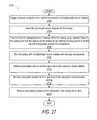
- FIG. 27 illustrates a method of using the casing and chassis provided by method 2600 ( FIG. 26 ).
- the method 2700 includes engaging compute components into the molded receptacles in the LWS chassis (block 2702 ).
- Method 2700 further includes inserting the LWS chassis into the casing (block 2704 ).
- Method 2700 further includes fully enclosing the LWS chassis within the casing using sealable flaps of the casing such that the casing can be utilized as an external shipping carton in which the IHS is physically shipped to a destination (block 2708 ).
- the method 2700 includes shipping the casing with the LWS chassis and compute components inserted therein (block 2708 ).
- the method 2700 may further include providing a selected removable portion by providing a required opening for power cabling (block 2710 ).
- the method 2700 may further include providing a selected removable portion by providing a required opening for communication cabling (block 2712 ).
- the method 2700 may further include providing a selected removable portion by providing a required opening for air flow (block 2714 ).
- one or more of the methods may be embodied in an automated manufacturing system that performs a series of functional processes. In some implementations, certain steps of the methods are combined, performed simultaneously or in a different order, or perhaps omitted, without deviating from the scope of the disclosure.
- the method blocks are described and illustrated in a particular sequence, use of a specific sequence of functional processes represented by the blocks is not meant to imply any limitations on the disclosure. Changes may be made with regards to the sequence of processes without departing from the scope of the present disclosure. Use of a particular sequence is therefore, not to be taken in a limiting sense, and the scope of the present disclosure is defined only by the appended claims.
- One or more of the embodiments of the disclosure described can be implementable, at least in part, using a software-controlled programmable processing device, such as a microprocessor, digital signal processor or other processing device, data processing apparatus or system.
- a computer program for configuring a programmable device, apparatus or system to implement the foregoing described methods is envisaged as an aspect of the present disclosure.
- the computer program may be embodied as source code or undergo compilation for implementation on a processing device, apparatus, or system.
- the computer program is stored on a carrier device in machine or device readable form, for example in solid-state memory, magnetic memory such as disk or tape, optically or magneto-optically readable memory such as compact disk or digital versatile disk, flash memory, etc.
- the processing device, apparatus or system utilizes the program or a part thereof to configure the processing device, apparatus, or system for operation.
Landscapes
- Engineering & Computer Science (AREA)
- Microelectronics & Electronic Packaging (AREA)
- Computer Hardware Design (AREA)
- General Engineering & Computer Science (AREA)
- Mechanical Engineering (AREA)
- Physics & Mathematics (AREA)
- Thermal Sciences (AREA)
- Packaging Of Machine Parts And Wound Products (AREA)
- Buffer Packaging (AREA)
- Management, Administration, Business Operations System, And Electronic Commerce (AREA)
Abstract
Description
Claims (19)
Priority Applications (1)
| Application Number | Priority Date | Filing Date | Title |
|---|---|---|---|
| US15/212,452 US10034405B2 (en) | 2014-06-09 | 2016-07-18 | Compute device casing that doubles as packaging and shipping container for the compute device |
Applications Claiming Priority (2)
| Application Number | Priority Date | Filing Date | Title |
|---|---|---|---|
| US14/299,182 US9445534B2 (en) | 2014-06-09 | 2014-06-09 | Compute device casing that doubles as packaging and shipping container for the compute device |
| US15/212,452 US10034405B2 (en) | 2014-06-09 | 2016-07-18 | Compute device casing that doubles as packaging and shipping container for the compute device |
Related Parent Applications (1)
| Application Number | Title | Priority Date | Filing Date |
|---|---|---|---|
| US14/299,182 Continuation US9445534B2 (en) | 2014-06-09 | 2014-06-09 | Compute device casing that doubles as packaging and shipping container for the compute device |
Publications (2)
| Publication Number | Publication Date |
|---|---|
| US20160330857A1 US20160330857A1 (en) | 2016-11-10 |
| US10034405B2 true US10034405B2 (en) | 2018-07-24 |
Family
ID=54770731
Family Applications (2)
| Application Number | Title | Priority Date | Filing Date |
|---|---|---|---|
| US14/299,182 Active 2035-01-20 US9445534B2 (en) | 2014-06-09 | 2014-06-09 | Compute device casing that doubles as packaging and shipping container for the compute device |
| US15/212,452 Active 2034-08-11 US10034405B2 (en) | 2014-06-09 | 2016-07-18 | Compute device casing that doubles as packaging and shipping container for the compute device |
Family Applications Before (1)
| Application Number | Title | Priority Date | Filing Date |
|---|---|---|---|
| US14/299,182 Active 2035-01-20 US9445534B2 (en) | 2014-06-09 | 2014-06-09 | Compute device casing that doubles as packaging and shipping container for the compute device |
Country Status (4)
| Country | Link |
|---|---|
| US (2) | US9445534B2 (en) |
| EP (1) | EP3152637B1 (en) |
| CN (1) | CN106462200A (en) |
| WO (1) | WO2015191109A1 (en) |
Cited By (1)
| Publication number | Priority date | Publication date | Assignee | Title |
|---|---|---|---|---|
| US11019757B2 (en) * | 2018-01-22 | 2021-05-25 | Wistron Corporation | Back cover module |
Families Citing this family (14)
| Publication number | Priority date | Publication date | Assignee | Title |
|---|---|---|---|---|
| US10362705B2 (en) * | 2014-06-09 | 2019-07-23 | Dell Products, L.P. | Lightweight server chassis configured for modular insertion of customer selectable components for downstream assembly of information handling system at customer locations |
| CN105630093B (en) * | 2014-10-30 | 2019-03-26 | 英业达科技有限公司 | Fixed device and server |
| US10229082B2 (en) * | 2015-11-09 | 2019-03-12 | Dell Products, Lp | System and method for providing wireless communications to a boxed server |
| KR102547948B1 (en) | 2018-08-30 | 2023-06-26 | 삼성전자주식회사 | Solid state drive apparatus including electrostactic prevention structure |
| CN113835494B (en) * | 2020-06-24 | 2024-02-13 | 戴尔产品有限公司 | Single-blade air damper for rack chassis |
| TWI777280B (en) * | 2020-10-27 | 2022-09-11 | 技嘉科技股份有限公司 | Expansion card housing, expansion card module and server |
| CN114428539B (en) * | 2020-10-29 | 2024-05-14 | 技钢科技股份有限公司 | Expansion card shell, expansion card module and server |
| US12317446B2 (en) | 2022-10-20 | 2025-05-27 | Dell Products L.P. | System and method for improving rate of air flow through data processing systems |
| US12200886B2 (en) | 2022-10-20 | 2025-01-14 | Dell Products L.P. | System and method for thermal management of removable components |
| US12133356B2 (en) | 2022-10-20 | 2024-10-29 | Dell Products L.P. | System and method for managing retaining cooling components in data processing systems |
| US12200898B2 (en) | 2022-10-20 | 2025-01-14 | Dell Products L.P. | System and method for managing component positioning and orientation in data processing systems |
| US12575020B2 (en) | 2022-10-20 | 2026-03-10 | Dell Products L.P. | System for thermal management of storage devices |
| US12174823B2 (en) | 2022-10-21 | 2024-12-24 | Dell Products L.P. | System and method to ensure data integrity of software defined storage system |
| US12101913B2 (en) | 2022-11-29 | 2024-09-24 | Dell Products L.P. | Variable topography heat sink fins |
Citations (25)
| Publication number | Priority date | Publication date | Assignee | Title |
|---|---|---|---|---|
| US4767003A (en) * | 1985-10-18 | 1988-08-30 | Hughes Aircraft Company | Transparent, electrostatic protective container with readily accessible identification means |
| US5303820A (en) | 1992-06-12 | 1994-04-19 | Claude Comtois | Packaging for protecting printed circuit board and other products |
| US5590781A (en) | 1994-01-24 | 1997-01-07 | Shackelford; Elisabeth | Unitary conformable shipping container |
| US6116423A (en) * | 1999-07-23 | 2000-09-12 | Texas Instruments Incorporated | Multi-functional shipping system for integrated circuit devices |
| US6242691B1 (en) | 1999-02-03 | 2001-06-05 | Lockheed Martin Corporation | Electronic packaging and method of packaging |
| US6305539B1 (en) | 1997-04-18 | 2001-10-23 | C. W. Sanders, Jr. | Shipping and storage container for laptop computers |
| US6425648B1 (en) | 2000-04-12 | 2002-07-30 | International Business Machines Corporation | Modular and flexible server frame enclosure |
| US20030041409A1 (en) | 2001-06-28 | 2003-03-06 | Caporale John L. | Adjustable-height castor system |
| US20030205498A1 (en) * | 2002-05-03 | 2003-11-06 | Maresh Mark Edmund | Packaging system for a component including a compressive and shock-absorbent packing insert |
| US20030213725A1 (en) * | 2002-03-29 | 2003-11-20 | Seiko Epson Corporation | Package and lower-package buffer member |
| US20030221914A1 (en) | 2002-05-28 | 2003-12-04 | Smith Paul L. | Portable lift for rack mounting equipment |
| US20070187836A1 (en) | 2006-02-15 | 2007-08-16 | Texas Instruments Incorporated | Package on package design a combination of laminate and tape substrate, with back-to-back die combination |
| US20070228900A1 (en) | 2006-04-03 | 2007-10-04 | Aopen Inc. | Dually foldable host unit case for a computer |
| US7370757B2 (en) * | 2005-06-02 | 2008-05-13 | Dell Products L.P. | Housing container and method for transporting a plurality of information handling systems |
| US20080236099A1 (en) | 2007-03-26 | 2008-10-02 | Avaya Technology Llc | Packaging for Electrical Equipment |
| US7628271B1 (en) | 2005-08-11 | 2009-12-08 | Richard Marton | Multi-functional carrying case for laptops and like portable computers |
| US20100236968A1 (en) * | 2009-03-18 | 2010-09-23 | Louis De Jesus | Packaging system and method |
| US7874433B2 (en) | 2005-04-28 | 2011-01-25 | Ortronics, Inc. | Seismically sound rack system |
| US8109389B1 (en) * | 2008-12-23 | 2012-02-07 | Genesee Packaging, Inc. | Shipping container assembly for electrical storage cells |
| US20120153785A1 (en) | 2010-12-17 | 2012-06-21 | Lai Chen-Ju | Package structure |
| US20120229971A1 (en) | 2011-03-10 | 2012-09-13 | Richard Steven Mills | Information handling system shared infrastructure chassis with flexible depth |
| US8413833B1 (en) | 2010-09-03 | 2013-04-09 | TCF Composites, LLC | Ruggedized composite rack mount transport case |
| US8424691B2 (en) | 2008-05-19 | 2013-04-23 | Chatsworth Products, Inc. | Seismically hardened two-post electronic equipment rack |
| US20130169127A1 (en) | 2011-09-26 | 2013-07-04 | Panasonic Corporation | Outer casing for electric device |
| US20130277252A1 (en) * | 2012-04-24 | 2013-10-24 | Dustin Moring | Mailing Package for a Light-Weight Product |
Family Cites Families (1)
| Publication number | Priority date | Publication date | Assignee | Title |
|---|---|---|---|---|
| US7012189B2 (en) | 2001-03-28 | 2006-03-14 | Apple Computer, Inc. | Computer enclosure |
-
2014
- 2014-06-09 US US14/299,182 patent/US9445534B2/en active Active
- 2014-12-23 WO PCT/US2014/072035 patent/WO2015191109A1/en not_active Ceased
- 2014-12-23 CN CN201480079682.8A patent/CN106462200A/en active Pending
- 2014-12-23 EP EP14894691.6A patent/EP3152637B1/en active Active
-
2016
- 2016-07-18 US US15/212,452 patent/US10034405B2/en active Active
Patent Citations (25)
| Publication number | Priority date | Publication date | Assignee | Title |
|---|---|---|---|---|
| US4767003A (en) * | 1985-10-18 | 1988-08-30 | Hughes Aircraft Company | Transparent, electrostatic protective container with readily accessible identification means |
| US5303820A (en) | 1992-06-12 | 1994-04-19 | Claude Comtois | Packaging for protecting printed circuit board and other products |
| US5590781A (en) | 1994-01-24 | 1997-01-07 | Shackelford; Elisabeth | Unitary conformable shipping container |
| US6305539B1 (en) | 1997-04-18 | 2001-10-23 | C. W. Sanders, Jr. | Shipping and storage container for laptop computers |
| US6242691B1 (en) | 1999-02-03 | 2001-06-05 | Lockheed Martin Corporation | Electronic packaging and method of packaging |
| US6116423A (en) * | 1999-07-23 | 2000-09-12 | Texas Instruments Incorporated | Multi-functional shipping system for integrated circuit devices |
| US6425648B1 (en) | 2000-04-12 | 2002-07-30 | International Business Machines Corporation | Modular and flexible server frame enclosure |
| US20030041409A1 (en) | 2001-06-28 | 2003-03-06 | Caporale John L. | Adjustable-height castor system |
| US20030213725A1 (en) * | 2002-03-29 | 2003-11-20 | Seiko Epson Corporation | Package and lower-package buffer member |
| US20030205498A1 (en) * | 2002-05-03 | 2003-11-06 | Maresh Mark Edmund | Packaging system for a component including a compressive and shock-absorbent packing insert |
| US20030221914A1 (en) | 2002-05-28 | 2003-12-04 | Smith Paul L. | Portable lift for rack mounting equipment |
| US7874433B2 (en) | 2005-04-28 | 2011-01-25 | Ortronics, Inc. | Seismically sound rack system |
| US7370757B2 (en) * | 2005-06-02 | 2008-05-13 | Dell Products L.P. | Housing container and method for transporting a plurality of information handling systems |
| US7628271B1 (en) | 2005-08-11 | 2009-12-08 | Richard Marton | Multi-functional carrying case for laptops and like portable computers |
| US20070187836A1 (en) | 2006-02-15 | 2007-08-16 | Texas Instruments Incorporated | Package on package design a combination of laminate and tape substrate, with back-to-back die combination |
| US20070228900A1 (en) | 2006-04-03 | 2007-10-04 | Aopen Inc. | Dually foldable host unit case for a computer |
| US20080236099A1 (en) | 2007-03-26 | 2008-10-02 | Avaya Technology Llc | Packaging for Electrical Equipment |
| US8424691B2 (en) | 2008-05-19 | 2013-04-23 | Chatsworth Products, Inc. | Seismically hardened two-post electronic equipment rack |
| US8109389B1 (en) * | 2008-12-23 | 2012-02-07 | Genesee Packaging, Inc. | Shipping container assembly for electrical storage cells |
| US20100236968A1 (en) * | 2009-03-18 | 2010-09-23 | Louis De Jesus | Packaging system and method |
| US8413833B1 (en) | 2010-09-03 | 2013-04-09 | TCF Composites, LLC | Ruggedized composite rack mount transport case |
| US20120153785A1 (en) | 2010-12-17 | 2012-06-21 | Lai Chen-Ju | Package structure |
| US20120229971A1 (en) | 2011-03-10 | 2012-09-13 | Richard Steven Mills | Information handling system shared infrastructure chassis with flexible depth |
| US20130169127A1 (en) | 2011-09-26 | 2013-07-04 | Panasonic Corporation | Outer casing for electric device |
| US20130277252A1 (en) * | 2012-04-24 | 2013-10-24 | Dustin Moring | Mailing Package for a Light-Weight Product |
Non-Patent Citations (2)
| Title |
|---|
| European Patent Office, European Search Report, EP Application No. 14894691.6, dated Jun. 7, 2017. |
| Patent Cooperation Treaty, ISA/US, International Application No. PCT/US14/72035, International Search Report and Written Opinion, dated Apr. 1, 2015. |
Cited By (1)
| Publication number | Priority date | Publication date | Assignee | Title |
|---|---|---|---|---|
| US11019757B2 (en) * | 2018-01-22 | 2021-05-25 | Wistron Corporation | Back cover module |
Also Published As
| Publication number | Publication date |
|---|---|
| EP3152637B1 (en) | 2023-10-04 |
| US20160330857A1 (en) | 2016-11-10 |
| US9445534B2 (en) | 2016-09-13 |
| CN106462200A (en) | 2017-02-22 |
| US20150359146A1 (en) | 2015-12-10 |
| EP3152637A4 (en) | 2017-07-05 |
| EP3152637A1 (en) | 2017-04-12 |
| WO2015191109A1 (en) | 2015-12-17 |
Similar Documents
| Publication | Publication Date | Title |
|---|---|---|
| US10034405B2 (en) | Compute device casing that doubles as packaging and shipping container for the compute device | |
| US10362705B2 (en) | Lightweight server chassis configured for modular insertion of customer selectable components for downstream assembly of information handling system at customer locations | |
| JP7434481B2 (en) | computerized packaging wall | |
| US10402890B2 (en) | Box-last packaging system, method, and computer program product | |
| US9235822B2 (en) | Optimization of packaging sizes | |
| US4241829A (en) | Means for containing electrostatic sensitive electronic components | |
| CN107624166B (en) | Smart phone packaging and virtual display headset | |
| US10743436B2 (en) | Provisioning of lightweight configurable servers with chassis base and cover designed for nested stacking | |
| US20160251112A1 (en) | Factory configurable shock pallet for various integrated rack weights | |
| CN107113990A (en) | Modularization information technology(IT)Frame and air current system | |
| EP3530573B1 (en) | Method and computer system for utilizing a converting machine for making custom packaging templates | |
| US20120153785A1 (en) | Package structure | |
| CN103198374B (en) | A kind of generation method and device of the PCB Component libraries for being adapted to specific user | |
| WO2007068079A1 (en) | Package with aperture | |
| JP2001114336A (en) | Returnable box for transportation work | |
| KR102435370B1 (en) | Article fixed packaging box using self-adhesive inlay and manufacturing method therefor | |
| JP2006327637A (en) | Container with ic tag, and packaging body with ic tag | |
| CN222743247U (en) | Adhesive tape-free packaging box | |
| CN218143293U (en) | Packaging structure of photovoltaic module | |
| CN213863540U (en) | Buffering package assembly | |
| JP7445492B2 (en) | Information provision system and shipping management device | |
| CN107600616B (en) | Package packing box and packaging method for CPU component productization | |
| SE515448C2 (en) | Apparatus for electromagnetic shielding in an electrical unit | |
| CN112429384A (en) | Industrial transport packaging box for electronic equipment | |
| JP2001171782A (en) | Storage container for semiconductor device |
Legal Events
| Date | Code | Title | Description |
|---|---|---|---|
| AS | Assignment |
Owner name: DELL PRODUCTS, L.P., TEXAS Free format text: ASSIGNMENT OF ASSIGNORS INTEREST;ASSIGNORS:BAILEY, EDMOND I.;CARVER, WALTER;EMBLETON, STEVEN;REEL/FRAME:039176/0747 Effective date: 20140603 |
|
| AS | Assignment |
Owner name: BANK OF AMERICA, N.A., AS ADMINISTRATIVE AGENT, NORTH CAROLINA Free format text: SUPPLEMENT TO PATENT SECURITY AGREEMENT (ABL);ASSIGNORS:AVENTAIL LLC;DELL PRODUCTS L.P.;DELL SOFTWARE INC.;AND OTHERS;REEL/FRAME:039643/0953 Effective date: 20160808 Owner name: THE BANK OF NEW YORK MELLON TRUST COMPANY, N.A., AS NOTES COLLATERAL AGENT, TEXAS Free format text: SUPPLEMENT TO PATENT SECURITY AGREEMENT (NOTES);ASSIGNORS:AVENTAIL LLC;DELL PRODUCTS L.P.;DELL SOFTWARE INC.;AND OTHERS;REEL/FRAME:039644/0084 Effective date: 20160808 Owner name: BANK OF AMERICA, N.A., AS COLLATERAL AGENT, NORTH CAROLINA Free format text: SUPPLEMENT TO PATENT SECURITY AGREEMENT (TERM LOAN);ASSIGNORS:AVENTAIL LLC;DELL PRODUCTS L.P.;DELL SOFTWARE INC.;AND OTHERS;REEL/FRAME:039719/0889 Effective date: 20160808 Owner name: BANK OF AMERICA, N.A., AS ADMINISTRATIVE AGENT, NO Free format text: SUPPLEMENT TO PATENT SECURITY AGREEMENT (ABL);ASSIGNORS:AVENTAIL LLC;DELL PRODUCTS L.P.;DELL SOFTWARE INC.;AND OTHERS;REEL/FRAME:039643/0953 Effective date: 20160808 Owner name: THE BANK OF NEW YORK MELLON TRUST COMPANY, N.A., A Free format text: SUPPLEMENT TO PATENT SECURITY AGREEMENT (NOTES);ASSIGNORS:AVENTAIL LLC;DELL PRODUCTS L.P.;DELL SOFTWARE INC.;AND OTHERS;REEL/FRAME:039644/0084 Effective date: 20160808 Owner name: BANK OF AMERICA, N.A., AS COLLATERAL AGENT, NORTH Free format text: SUPPLEMENT TO PATENT SECURITY AGREEMENT (TERM LOAN);ASSIGNORS:AVENTAIL LLC;DELL PRODUCTS L.P.;DELL SOFTWARE INC.;AND OTHERS;REEL/FRAME:039719/0889 Effective date: 20160808 |
|
| AS | Assignment |
Owner name: AVENTAIL LLC, CALIFORNIA Free format text: RELEASE OF SEC. INT. IN PATENTS (ABL);ASSIGNOR:BANK OF AMERICA, N.A., AS ADMINISTRATIVE AGENT;REEL/FRAME:040013/0733 Effective date: 20160907 Owner name: DELL PRODUCTS L.P., TEXAS Free format text: RELEASE OF SEC. INT. IN PATENTS (ABL);ASSIGNOR:BANK OF AMERICA, N.A., AS ADMINISTRATIVE AGENT;REEL/FRAME:040013/0733 Effective date: 20160907 Owner name: FORCE10 NETWORKS, INC., CALIFORNIA Free format text: RELEASE OF SEC. INT. IN PATENTS (ABL);ASSIGNOR:BANK OF AMERICA, N.A., AS ADMINISTRATIVE AGENT;REEL/FRAME:040013/0733 Effective date: 20160907 Owner name: DELL SOFTWARE INC., CALIFORNIA Free format text: RELEASE OF SEC. INT. IN PATENTS (ABL);ASSIGNOR:BANK OF AMERICA, N.A., AS ADMINISTRATIVE AGENT;REEL/FRAME:040013/0733 Effective date: 20160907 Owner name: WYSE TECHNOLOGY L.L.C., CALIFORNIA Free format text: RELEASE OF SEC. INT. IN PATENTS (ABL);ASSIGNOR:BANK OF AMERICA, N.A., AS ADMINISTRATIVE AGENT;REEL/FRAME:040013/0733 Effective date: 20160907 |
|
| AS | Assignment |
Owner name: DELL SOFTWARE INC., CALIFORNIA Free format text: RELEASE OF SEC. INT. IN PATENTS (TL);ASSIGNOR:BANK OF AMERICA, N.A., AS COLLATERAL AGENT;REEL/FRAME:040027/0329 Effective date: 20160907 Owner name: AVENTAIL LLC, CALIFORNIA Free format text: RELEASE OF SEC. INT. IN PATENTS (NOTES);ASSIGNOR:BANK OF NEW YORK MELLON TRUST COMPANY, N.A., AS COLLATERAL AGENT;REEL/FRAME:040026/0710 Effective date: 20160907 Owner name: DELL PRODUCTS L.P., TEXAS Free format text: RELEASE OF SEC. INT. IN PATENTS (TL);ASSIGNOR:BANK OF AMERICA, N.A., AS COLLATERAL AGENT;REEL/FRAME:040027/0329 Effective date: 20160907 Owner name: FORCE10 NETWORKS, INC., CALIFORNIA Free format text: RELEASE OF SEC. INT. IN PATENTS (TL);ASSIGNOR:BANK OF AMERICA, N.A., AS COLLATERAL AGENT;REEL/FRAME:040027/0329 Effective date: 20160907 Owner name: WYSE TECHNOLOGY L.L.C., CALIFORNIA Free format text: RELEASE OF SEC. INT. IN PATENTS (TL);ASSIGNOR:BANK OF AMERICA, N.A., AS COLLATERAL AGENT;REEL/FRAME:040027/0329 Effective date: 20160907 Owner name: AVENTAIL LLC, CALIFORNIA Free format text: RELEASE OF SEC. INT. IN PATENTS (TL);ASSIGNOR:BANK OF AMERICA, N.A., AS COLLATERAL AGENT;REEL/FRAME:040027/0329 Effective date: 20160907 Owner name: DELL PRODUCTS L.P., TEXAS Free format text: RELEASE OF SEC. INT. IN PATENTS (NOTES);ASSIGNOR:BANK OF NEW YORK MELLON TRUST COMPANY, N.A., AS COLLATERAL AGENT;REEL/FRAME:040026/0710 Effective date: 20160907 Owner name: DELL SOFTWARE INC., CALIFORNIA Free format text: RELEASE OF SEC. INT. IN PATENTS (NOTES);ASSIGNOR:BANK OF NEW YORK MELLON TRUST COMPANY, N.A., AS COLLATERAL AGENT;REEL/FRAME:040026/0710 Effective date: 20160907 Owner name: FORCE10 NETWORKS, INC., CALIFORNIA Free format text: RELEASE OF SEC. INT. IN PATENTS (NOTES);ASSIGNOR:BANK OF NEW YORK MELLON TRUST COMPANY, N.A., AS COLLATERAL AGENT;REEL/FRAME:040026/0710 Effective date: 20160907 Owner name: WYSE TECHNOLOGY L.L.C., CALIFORNIA Free format text: RELEASE OF SEC. INT. IN PATENTS (NOTES);ASSIGNOR:BANK OF NEW YORK MELLON TRUST COMPANY, N.A., AS COLLATERAL AGENT;REEL/FRAME:040026/0710 Effective date: 20160907 |
|
| STCF | Information on status: patent grant |
Free format text: PATENTED CASE |
|
| AS | Assignment |
Owner name: THE BANK OF NEW YORK MELLON TRUST COMPANY, N.A., AS COLLATERAL AGENT, TEXAS Free format text: PATENT SECURITY AGREEMENT (NOTES);ASSIGNORS:DELL PRODUCTS L.P.;EMC CORPORATION;EMC IP HOLDING COMPANY LLC;REEL/FRAME:047648/0422 Effective date: 20180906 Owner name: CREDIT SUISSE AG, CAYMAN ISLANDS BRANCH, AS COLLATERAL AGENT, NORTH CAROLINA Free format text: PATENT SECURITY AGREEMENT (CREDIT);ASSIGNORS:DELL PRODUCTS L.P.;EMC CORPORATION;EMC IP HOLDING COMPANY LLC;REEL/FRAME:047648/0346 Effective date: 20180906 Owner name: CREDIT SUISSE AG, CAYMAN ISLANDS BRANCH, AS COLLAT Free format text: PATENT SECURITY AGREEMENT (CREDIT);ASSIGNORS:DELL PRODUCTS L.P.;EMC CORPORATION;EMC IP HOLDING COMPANY LLC;REEL/FRAME:047648/0346 Effective date: 20180906 Owner name: THE BANK OF NEW YORK MELLON TRUST COMPANY, N.A., A Free format text: PATENT SECURITY AGREEMENT (NOTES);ASSIGNORS:DELL PRODUCTS L.P.;EMC CORPORATION;EMC IP HOLDING COMPANY LLC;REEL/FRAME:047648/0422 Effective date: 20180906 |
|
| AS | Assignment |
Owner name: THE BANK OF NEW YORK MELLON TRUST COMPANY, N.A., T Free format text: SECURITY AGREEMENT;ASSIGNORS:CREDANT TECHNOLOGIES, INC.;DELL INTERNATIONAL L.L.C.;DELL MARKETING L.P.;AND OTHERS;REEL/FRAME:049452/0223 Effective date: 20190320 Owner name: THE BANK OF NEW YORK MELLON TRUST COMPANY, N.A., TEXAS Free format text: SECURITY AGREEMENT;ASSIGNORS:CREDANT TECHNOLOGIES, INC.;DELL INTERNATIONAL L.L.C.;DELL MARKETING L.P.;AND OTHERS;REEL/FRAME:049452/0223 Effective date: 20190320 |
|
| AS | Assignment |
Owner name: THE BANK OF NEW YORK MELLON TRUST COMPANY, N.A., TEXAS Free format text: SECURITY AGREEMENT;ASSIGNORS:CREDANT TECHNOLOGIES INC.;DELL INTERNATIONAL L.L.C.;DELL MARKETING L.P.;AND OTHERS;REEL/FRAME:053546/0001 Effective date: 20200409 |
|
| AS | Assignment |
Owner name: EMC IP HOLDING COMPANY LLC, TEXAS Free format text: RELEASE OF SECURITY INTEREST AT REEL 047648 FRAME 0346;ASSIGNOR:CREDIT SUISSE AG, CAYMAN ISLANDS BRANCH;REEL/FRAME:058298/0510 Effective date: 20211101 Owner name: EMC CORPORATION, MASSACHUSETTS Free format text: RELEASE OF SECURITY INTEREST AT REEL 047648 FRAME 0346;ASSIGNOR:CREDIT SUISSE AG, CAYMAN ISLANDS BRANCH;REEL/FRAME:058298/0510 Effective date: 20211101 Owner name: DELL PRODUCTS L.P., TEXAS Free format text: RELEASE OF SECURITY INTEREST AT REEL 047648 FRAME 0346;ASSIGNOR:CREDIT SUISSE AG, CAYMAN ISLANDS BRANCH;REEL/FRAME:058298/0510 Effective date: 20211101 |
|
| MAFP | Maintenance fee payment |
Free format text: PAYMENT OF MAINTENANCE FEE, 4TH YEAR, LARGE ENTITY (ORIGINAL EVENT CODE: M1551); ENTITY STATUS OF PATENT OWNER: LARGE ENTITY Year of fee payment: 4 |
|
| AS | Assignment |
Owner name: DELL MARKETING L.P. (ON BEHALF OF ITSELF AND AS SUCCESSOR-IN-INTEREST TO CREDANT TECHNOLOGIES, INC.), TEXAS Free format text: RELEASE OF SECURITY INTEREST IN PATENTS PREVIOUSLY RECORDED AT REEL/FRAME (053546/0001);ASSIGNOR:THE BANK OF NEW YORK MELLON TRUST COMPANY, N.A., AS NOTES COLLATERAL AGENT;REEL/FRAME:071642/0001 Effective date: 20220329 Owner name: DELL INTERNATIONAL L.L.C., TEXAS Free format text: RELEASE OF SECURITY INTEREST IN PATENTS PREVIOUSLY RECORDED AT REEL/FRAME (053546/0001);ASSIGNOR:THE BANK OF NEW YORK MELLON TRUST COMPANY, N.A., AS NOTES COLLATERAL AGENT;REEL/FRAME:071642/0001 Effective date: 20220329 Owner name: DELL PRODUCTS L.P., TEXAS Free format text: RELEASE OF SECURITY INTEREST IN PATENTS PREVIOUSLY RECORDED AT REEL/FRAME (053546/0001);ASSIGNOR:THE BANK OF NEW YORK MELLON TRUST COMPANY, N.A., AS NOTES COLLATERAL AGENT;REEL/FRAME:071642/0001 Effective date: 20220329 Owner name: DELL USA L.P., TEXAS Free format text: RELEASE OF SECURITY INTEREST IN PATENTS PREVIOUSLY RECORDED AT REEL/FRAME (053546/0001);ASSIGNOR:THE BANK OF NEW YORK MELLON TRUST COMPANY, N.A., AS NOTES COLLATERAL AGENT;REEL/FRAME:071642/0001 Effective date: 20220329 Owner name: EMC CORPORATION, MASSACHUSETTS Free format text: RELEASE OF SECURITY INTEREST IN PATENTS PREVIOUSLY RECORDED AT REEL/FRAME (053546/0001);ASSIGNOR:THE BANK OF NEW YORK MELLON TRUST COMPANY, N.A., AS NOTES COLLATERAL AGENT;REEL/FRAME:071642/0001 Effective date: 20220329 Owner name: DELL MARKETING CORPORATION (SUCCESSOR-IN-INTEREST TO FORCE10 NETWORKS, INC. AND WYSE TECHNOLOGY L.L.C.), TEXAS Free format text: RELEASE OF SECURITY INTEREST IN PATENTS PREVIOUSLY RECORDED AT REEL/FRAME (053546/0001);ASSIGNOR:THE BANK OF NEW YORK MELLON TRUST COMPANY, N.A., AS NOTES COLLATERAL AGENT;REEL/FRAME:071642/0001 Effective date: 20220329 Owner name: EMC IP HOLDING COMPANY LLC, TEXAS Free format text: RELEASE OF SECURITY INTEREST IN PATENTS PREVIOUSLY RECORDED AT REEL/FRAME (053546/0001);ASSIGNOR:THE BANK OF NEW YORK MELLON TRUST COMPANY, N.A., AS NOTES COLLATERAL AGENT;REEL/FRAME:071642/0001 Effective date: 20220329 |
|
| MAFP | Maintenance fee payment |
Free format text: PAYMENT OF MAINTENANCE FEE, 8TH YEAR, LARGE ENTITY (ORIGINAL EVENT CODE: M1552); ENTITY STATUS OF PATENT OWNER: LARGE ENTITY Year of fee payment: 8 |