US10026132B2 - Chronological information mapping - Google Patents
Chronological information mapping Download PDFInfo
- Publication number
- US10026132B2 US10026132B2 US14/810,954 US201514810954A US10026132B2 US 10026132 B2 US10026132 B2 US 10026132B2 US 201514810954 A US201514810954 A US 201514810954A US 10026132 B2 US10026132 B2 US 10026132B2
- Authority
- US
- United States
- Prior art keywords
- user
- chronological
- display
- line item
- display structure
- Prior art date
- Legal status (The legal status is an assumption and is not a legal conclusion. Google has not performed a legal analysis and makes no representation as to the accuracy of the status listed.)
- Active, expires
Links
Images


Classifications
-
- G—PHYSICS
- G06—COMPUTING; CALCULATING OR COUNTING
- G06Q—INFORMATION AND COMMUNICATION TECHNOLOGY [ICT] SPECIALLY ADAPTED FOR ADMINISTRATIVE, COMMERCIAL, FINANCIAL, MANAGERIAL OR SUPERVISORY PURPOSES; SYSTEMS OR METHODS SPECIALLY ADAPTED FOR ADMINISTRATIVE, COMMERCIAL, FINANCIAL, MANAGERIAL OR SUPERVISORY PURPOSES, NOT OTHERWISE PROVIDED FOR
- G06Q50/00—Systems or methods specially adapted for specific business sectors, e.g. utilities or tourism
- G06Q50/01—Social networking
-
- G—PHYSICS
- G06—COMPUTING; CALCULATING OR COUNTING
- G06Q—INFORMATION AND COMMUNICATION TECHNOLOGY [ICT] SPECIALLY ADAPTED FOR ADMINISTRATIVE, COMMERCIAL, FINANCIAL, MANAGERIAL OR SUPERVISORY PURPOSES; SYSTEMS OR METHODS SPECIALLY ADAPTED FOR ADMINISTRATIVE, COMMERCIAL, FINANCIAL, MANAGERIAL OR SUPERVISORY PURPOSES, NOT OTHERWISE PROVIDED FOR
- G06Q10/00—Administration; Management
- G06Q10/10—Office automation; Time management
Abstract
An activity is detected in a computer system. The activity is correlated to a given entity. A line item display is generated for the detected activity and contextual actions are identified for the line item display. The line item display, with contextual action mechanisms is added to a chronological display structure which is surfaced for user interaction.
Description
Computing systems are currently in wide use. Many computing systems are deployed by organizations in order to facilitate the performance of tasks needed to run the organization.
When issues arise with respect to the operation of a given computing system, many different people can be involved in performing a wide variety of different tasks, in order to address the issue. Some issues with computing systems can be long running issues that are relatively complex in nature. Information used by those involved in addressing the issue can come from a wide variety of different sources. For instance, it can come from a knowledge base, an enterprise application (such as ERP or CRM applications or line-of-business applications), email systems, the email systems of external users (such as customers), inputs from engineers, technical information, manuals, etc. Some of this information may be relevant to some users, but be completely irrelevant to other users.
In addition, there may be a variety of different types of information that are relevant to the issue being addressed. Such information can include telephone conversations, emails, messages, meetings, actions taken by engineering personnel, and a wide variety of other information. It can be difficult for a user who is addressing the computing system issue to access all of this information in a meaningful way.
Also, the process by which a computing system issue is resolved can be generally unstructured. That is, each computing system issue may need a unique process or set of steps in order to address it. Thus, capturing relevant information and making it accessible in a meaningful way can be further exacerbated by the nature of the processes used to resolve such issues.
The discussion above is merely provided for general background information and is not intended to be used as an aid in determining the scope of the claimed subject matter.
An activity is detected in a computer system. The activity is correlated to a given entity. A line item display is generated for the detected activity and contextual actions are identified for the line item display. The line item display, with contextual action mechanisms is added to a chronological display structure which is surfaced for user interaction.
This Summary is provided to introduce a selection of concepts in a simplified form that are further described below in the Detailed Description. This Summary is not intended to identify key features or essential features of the claimed subject matter, nor is it intended to be used as an aid in determining the scope of the claimed subject matter. The claimed subject matter is not limited to implementations that solve any or all disadvantages noted in the background.
In the example shown in FIG. 1 , computing system 102 illustratively includes processors or servers 116, application component 118, user interface component 120, data store 122, visualization system 124, communication channels (or communication systems) 126, chronological information generation system 127 (which, itself, can include linguistic processing system 128, line item generator 129, timeline structure configuration system 130, issue correlation component 132, and contextual action identifier 178) and it can include other items 134.
In the example shown in FIG. 1 , visualization system 124 can include chronological display generator 170 (which, itself, can include role identifier 172 and view generator 174), customer data import component 176, interaction processing component 179, user interface (UI) capability component 180, timeline search/filter system 182, customer view generator 184, summary generator 186, and it can include other items 188. Communication channels 126 can include a wide variety of different types of systems that can enable communication between users, external users, or other entities, and computing system 102. For instance, channels 126 can include scheduling system 189, email system 190, telephone/cellular system 192, messaging system 194, social network system 196, and it can include other items 198. Linguistic processing system 128 illustratively includes sentiment analyzer 200, natural language processing (NLP) component 202, (which can also include speech recognition and speech synthesis components) and it can include other items 204. Before describing the overall operation of computing system 102 in more detail, a brief overview of sonic of the items in computing system 102, and their operation, will first be provided.
Chronological information generation system 127 illustratively allows a user to configure different chronological display structures (or timeline views) to be generated, and then populates them during runtime. For instance, timeline structure configuration system 130 illustratively allows a user 110 (such as an administrative user or other user), to configure or specify the types of activities that are to be included in a chronological display structure (or timeline display structure) being configured by the user 110. It may, for example, be that the user 110 wishes the timeline display structure to show all activities related to a computing system issue that is raised by a given external user (or customer) 114. When such a timeline display structure is populated during runtime, activity detector 131 detects when any of the activities occur and issue correlation component 132 correlates them to the particular issue, external user (e.g., customer), computing system, or other items for which the timeline display structure is to be generated. Line item generator 129 generates a line item display that represents the detected activity. Contextual action identifier 178 identifies contextual actions that may be available for each of the line items generated by line item generator 129, in the chronological display structure 144 and provides user input mechanisms that allow user 110 to perform contextual actions with respect to each of the line items. Representations of those activities are then stored in data store 122 and the line items are also stored as chronological map information 146 in the chronological display structure 144 to which the activity has been correlated.
It will be appreciated that the context can include a wide variety of things. It can, for instance, include which application generated the detected activity (an email, a social network post, etc.). It can include an entity or process or workflow affected by the activity (e.g., customer complaint, customer issue process, etc.). It can, of course, include other things as well. The contextual actions can take a wide variety of different forms. They can be based on the type of activity that the line item represents, or the status of the line item, etc. For instance, a line item that represents a closed phone call activity may include contextual action mechanisms that allow the user to play a recording of the phone call, to view notes from the phone call or to view details from the phone call. A line item that represents an open phone call activity may include contextual mechanisms that allow the user to edit a phone call record, mark it completed, create a follow up or send an email. A line item that represents an article may provide contextual mechanisms that allow the user to copy a link to the article, send an email with the article, link or unlink the article to other items, etc. Where the line item represents an activity that is a search by a customer, the contextual action mechanisms may allow the user to view the search results that were displayed to the customer, access those search results, etc. Where the line item represents an activity that is a closed chat activity, the mechanisms may allow the user to view a transcript of the chat. Where it is an open chat conversation, the mechanisms may allow the user to continue the chat, send an attachment, send a link to an article, convert the chat activity to a case, etc. Of course, these are examples only.
The chronological display structure illustrated in FIGS. 2B-2D also illustratively includes recent update section 336. It includes a set of recent updates 338 which can be added to a recent update queue and displayed when the chronological display structure is requested. It can also include a wide variety of different types of metrics that can be calculated by summary generator 136 in visualization system 124 (in FIG. 1 ) when the chronological display structure is displayed. The metrics shown in FIG. 2D can be pre-computed or computed on-the-fly and can, for instance, include a total number of tickets 340, a feedback section 342, a receivables section 344, and a variety of other types of scores or metric information 346.
In addition, the chronological display structure can include a portal activity section 348. Section 348 illustratively identifies recent activities or web portal interactions that occurred just prior to creation of the customer issue ticket represented by the chronological display structure shown in FIGS. 2B-2D . For instance, it indicates that a plurality of different searches were performed through the portal. It indicates that a set of articles were read, and commented, and that a user's address or phone number was updated.
The user configuring the structure can also indicate that the role-specific view will incorporate role-specific privileges. For instance, a line item may have different read/write/update access for different roles. An external user 114, for instance, may be able to view a line item, but not change the status of the line item. Further, a user with a given role may not have access to certain information in the chronological display structure. When that user, with that particular role, accesses the chronological display structure, the information may be collapsed or hidden. However, when a user with a different role (who has access to the information) views the chronological display structure, then the information will be expanded so that the latter user has access to all of the information regarding the issue represented by the chronological display structure. In any case, for purposes of the present discussion, it is assumed at block 270 that the various chronological display structures have already been configured or defined.
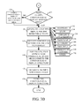
Once the chronological display structures have been defined, system 102 can then detect an input indicative of a desire to open a chronological display structure. This is indicated by block 272. For instance, a customer service user may receive a call from a customer indicating a new issue. The customer service user may then provide an input indicating that the user wishes to open a chronological display structure for the new issue. Detecting a user input is indicated by block 274. Alternatively, a customer may call or send an email, or comment on a company's website, indicating that the customer has an issue. Detecting a customer interaction is indicated by block 276. Detecting an input to open a new chronological display structure can be done in other ways as well, and this is indicated by block 278.
Customer data import component 176 then retrieves customer data for validation by the user who is opening the chronological display structure for the new customer issue. This is indicated by block 280. This can be done by having the user enter preliminary information (such as the customer name, etc.). This is indicated by block 282. The import component 176 can then access a wide variety of different types of customer data in data store 122, as indicated by block 284. Import component 176 then populates the chronological display structure that has been opened by the user and displays the customer data to the user for validation. This is indicated by block 286. The customer data can be retrieved for validation in other ways as well, and this is indicated by block 288.
Once the chronological display structure has been opened and populated with data for a customer issue, then activity detector 131 can detect a wide variety of different types of activities that are to be included in the chronological display structure. Detecting an activity to be included is indicated by block 290. The detected activities can be a communication 292, which can be internal communication within the organization using computing system 102, or it can be a communication with an external user (e.g., a customer). The communication can take a wide variety of different forms, such as a call, a message, an email, etc. The detected activity can be that a user has entered notes with respect to the issue represented by the chronological display structure. This is indicated by block 294. It can be that an appointment has been scheduled as indicated by block 296 or that a search was performed for relevant information, as indicated by block 298. It can be a customer-initiated activity (such as an email, a post on a website, etc.) as indicated by block 400. It can be a metadata update (such as changing the priority of an issue from low to medium, etc.). This is indicated by block 402. It can be a state update (such as by changing the status of the issue from open or active to “resolved”). This is indicated by block 404. The activity can be a timeline violation or other alert (such as when a customer service representative promises a customer that an issue will be resolved or a delivery will be made by a given date, and that date has passed). A timeline violation or other alert is indicated by block 406. It can be an association of content with an issue (such as providing a link to a document, a video, or other content). This is indicated by block 408. The activity can take a wide variety of other forms as well, and this is indicated by block 410.
After activity detector 131 detects the activity, issue correlation component 132 illustratively correlates the detected activity with an issue, a customer, a chronological display structure, etc. This is indicated by block 412. This can be done in a variety of different ways. For instance, if the activity is a communication (such as an email, a call, a message, etc.) then correlation component 132 illustratively accesses header information 414 corresponding to the detected activity. The header information may identify the customer, a case number, or have a variety of other identifying information that can be used to correlate the activity. The activity may have a “regarding” object or field 416 that also indicates identifying information that may be used to correlate the activity. For instance, a customer may include a case number in the “regarding” object. This can be used to correlate the activity to an issue, a customer, a chronological display structure, etc. The case number 418 can be identified in other ways, or other information 420 can be used to correlate the activity.
It may be that, when the chronological display structure is opened and populated, it is simultaneously displayed to a user for user interaction. It may also be, however, that the chronological display structure is stored and accessed later by a user. In either case, visualization system 124 illustratively generates a role-specific visualization of the chronological display structure for the user. FIG. 4 illustrates one example of the operation of visualization system 124 in surfacing a visualization of the chronological display structure for user interaction.
The detected user interactions can also be that the user has actuated a contextual action mechanism. This is indicated by block 470. Further, they can be that the user has provided an input to perform UI functionality. Such functionality can be, for instance, to collapse certain line items or expand them, to group or ungroup line items, or a wide variety of other UI functionality. This is indicated by block 472. The detected user interaction can take a wide variety of other forms as well. This is indicated by block 474.
In response, visualization system 124 performs various actions based upon the detected user interaction. This is indicated by block 476. For instance, if the user provides a timeline search/filter input, then timeline search/filter system 182 illustratively filters the line items or other items on the chronological display structure based on the search or filter inputs. If the user actuates a contextual action mechanism, then the application component 118 performs the contextual action based on the detected user interaction. If the user actuates user interface mechanisms to perform UI functionality, then UI capability component 180 performs the UI functionality based upon the detected user interaction. Of course, these are examples only.
When the user validates the data by actuating mechanism 490, FIG. 5C shows that the additional customer information 492 can be displayed for user 110. The chronological display structure can now be populated with line items.
In the example shown in FIG. 5C , it can be seen that the user is actuating a notes user input mechanism 494 that can be used to enter notes on the chronological display structure. FIG. 5D shows that the user has entered the notes “unable to upload video on cloud storage” in notes user input mechanism 494. The user can confirm this by actuating an enter user input mechanism 496. When this happens, a line item 498 is generated that reflects the activity of the user entering notes. This is illustrated in FIG. 5E .
It will be appreciated that FIGS. 5A-5G show only one example of how a chronological display structure can be opened and populated with a relatively small number of line items, reflecting a relatively small number of activities. It will be appreciated, however, that a wide variety of different types of activities can be detected and included in the display structure, and they can be detected and included over a long period of time, from a wide variety of sources, communication channels, etc. Therefore, a user who later accesses the display structure can see precisely what happened, when, how recently, etc.
It can thus be seen that the present system advantageously aggregates information that is correlated to a given issue, customer, etc., from a wide variety of different channels or sources. The information can be from a variety of different communication systems, from a variety of different applications, from a variety of different data sources, etc. The information that is relevant to a given role is illustratively aggregated from all of those different channels or systems, and presented in a chronological fashion. The data that may be relevant to a user having one role is presented for that role, while different data, that may be relevant to user having a second role, is surfaced for the user having the second role. This improves the processing of the computing system, itself, in that it reduces the processing overhead needed for navigating, searching, and rendering of the information. Whereas, in prior systems, a user may need to search multiple different data stores storing information for multiple different channels or systems, and then navigate to those different data stores to view all of this type of information, the present system aggregates it and surfaces it in a single view. This can significantly reduce network traffic, search and navigation processing overhead, and rendering overhead.
It also illustratively increases the efficiency of the users. They need not search multiple different locations in order to find information relevant to a given issue and attempt to piece that information together, themselves, chronologically, to determine when activities took place relative to one another. Instead, the present system advantageously generates a chronological display structure and selectively includes or excludes detected activities, based upon the underlying configuration of the structure, for surfacing.
The present system also advantageously includes contextual user input mechanisms, with each line item generated, so that a user can directly take action from the chronological display structure, within the context of each line item. The contextual actions can be based on the type of the line item they're associated with, what or who performed the activity represented by the line item, based on a current state of the line item, etc.
The present system also advantageously allows the user to quickly and easily filter and search through the display structure by applying multiple filters, by using keywords, ownership, date, customer initiation, etc. as filter criteria. The present system also illustratively and advantageously applies permissions and access rights to the various information in the chronological display structure. Thus, the security of the information is maintained.
The present discussion has mentioned processors and servers. In one embodiment, the processors and servers include computer processors with associated memory and timing circuitry, not separately shown. They are functional parts of the systems or devices to which they belong and are activated by, and facilitate the functionality of the other components or items in those systems.
Also, a number of user interface displays have been discussed. They can take a wide variety of different forms and can have a wide variety of different user actuatable input mechanisms disposed thereon. For instance, the user actuatable input mechanisms can be text boxes, check boxes, icons, links, drop-down menus, search boxes, etc. They can also be actuated in a wide variety of different ways. For instance, they can be actuated using a point and click device (such as a track ball or mouse). They can be actuated using hardware buttons, switches, a joystick or keyboard, thumb switches or thumb pads, etc. They can also be actuated using a virtual keyboard or other virtual actuators. In addition, where the screen on which they are displayed is a touch sensitive screen, they can be actuated using touch gestures. Also, where the device that displays them has speech recognition components, they can be actuated using speech commands.
A number of data stores have also been discussed. It will be noted they can each be broken into multiple data stores. All can be local to the systems accessing them, all can be remote, or some can be local while others are remote. All of these configurations are contemplated herein.
Also, the figures show a number of blocks with functionality ascribed to each block. It will be noted that fewer blocks can be used so the functionality is performed by fewer components. Also, more blocks can be used with the functionality distributed among more components.
The description is intended to include both public cloud computing and private cloud computing. Cloud computing (both public and private) provides substantially seamless pooling of resources, as well as a reduced need to manage and configure underlying hardware infrastructure.
A public cloud is managed by a vendor and typically supports multiple consumers using the same infrastructure. Also, a public cloud, as opposed to a private cloud, can free up the end users from managing the hardware. A private cloud may be managed by the organization itself and the infrastructure is typically not shared with other organizations. The organization still maintains the hardware to some extent, such as installations and repairs, etc.
In the example shown in FIG. 6 , some items are similar to those shown in FIG. 1 and they are similarly numbered. FIG. 6 specifically shows that computing system 102 can be located in cloud 502 (which can be public, private, or a combination where portions are public while others are private). Therefore, user 110 uses a user device 504 to access those systems through cloud 502.
It will also be noted that architecture 100, or portions of it, can be disposed on a wide variety of different devices. Some of those devices include servers, desktop computers, laptop computers, tablet computers, or other mobile devices, such as palm top computers, cell phones, smart phones, multimedia players, personal digital assistants, etc.
Under other embodiments, applications or systems (like on-premise business application 176) are received on a removable Secure Digital (SD) card that is connected to a SD card interface 15. SD card interface 15 and communication links 13 communicate with a processor 17 (which can also embody processors or servers from previous Figures) along a bus 19 that is also connected to memory 21 and input/output (I/O) components 23, as well as clock 25 and location system 27.
I/O components 23, in one embodiment, are provided to facilitate input and output operations. I/O components 23 for various embodiments of the device 16 can include input components such as buttons, touch sensors, multi-touch sensors, optical or video sensors, voice sensors, touch screens, proximity sensors, microphones, tilt sensors, and gravity switches and output components such as a display device, a speaker, and or a printer port. Other I/O components 23 can be used as well.
Examples of the network settings 31 include things such as proxy information, Internet connection information, and mappings. Application configuration settings 35 include settings that tailor the application for a specific enterprise or user. Communication configuration settings 41 provide parameters for communicating with other computers and include items such as GPRS parameters, SMS parameters, connection user names and passwords.
Additional examples of devices 16 can be used as well. Device 16 can be, a feature phone, smart phone or mobile phone. The phone can include a set of keypads for dialing phone numbers, a display capable of displaying images including application images, icons, web pages, photographs, and video, and control buttons for selecting items shown on the display. The phone can include an antenna for receiving cellular phone signals such as General Packet Radio Service (GPRS) and 1×rtt, and Short Message Service (SMS) signals. In some examples the phone also includes a Secure Digital (SD) card slot that accepts a SD card.
The mobile device can also be a personal digital assistant or a multimedia player or a tablet computing device, etc. (hereinafter referred to as a PDA). The PDA can include an inductive screen that senses the position of a stylus (or other pointers, such as a user's finger) when the stylus is positioned over the screen. This allows the user to select, highlight, and move items on the screen as well as draw and write. The PDA can also include a number of user input keys or buttons which allow the user to scroll through menu options or other display options which are displayed on the display, and allow the user to change applications or select user input functions, without contacting the display. The PDA can also include an internal antenna and an infrared transmitter/receiver that allow for wireless communication with other computers as well as connection ports that allow for hardware connections to other computing devices. Such hardware connections are typically made through a cradle that connects to the other computer through a serial or USB port. As such, these connections are non-network connections.
Note that other forms of the devices 16 are possible.
The system memory 830 includes computer storage media in the form of volatile and/or nonvolatile memory such as read only memory (ROM) 831 and random access memory (RAM) 832. A basic input/output system 833 (BIOS), containing the basic routines that help to transfer information between elements within computer 810, such as during start-up, is typically stored in ROM 831. RAM 832 typically contains data and/or program modules that are immediately accessible to and/or presently being operated on by processing unit 820. By way of example, and not limitation, FIG. 10 illustrates operating system 834, application programs 835, other program modules 836, and program data 837.
The computer 810 may also include other removable/non-removable volatile/nonvolatile computer storage media. By way of example only, FIG. 10 illustrates a hard disk drive 841 that reads from or writes to non-removable, nonvolatile magnetic media, and an optical disk drive 855 that reads from or writes to a removable, nonvolatile optical disk 856 such as a CD ROM or other optical media. Other removable/non-removable, volatile/nonvolatile computer storage media that can be used in the exemplary operating environment include, but are not limited to, magnetic tape cassettes, flash memory cards, digital versatile disks, digital video tape, solid state RAM, solid state ROM, and the like. The hard disk drive 841 is typically connected to the system bus 821 through a non-removable memory interface such as interface 840, and optical disk drive 855 are typically connected to the system bus 821 by a removable memory interface, such as interface 850.
Alternatively, or in addition, the functionality described herein can be performed, at least in part, by one or more hardware logic components. For example, and without limitation, illustrative types of hardware logic components that can be used include Field-programmable Gate Arrays (FPGAs), Program-specific Integrated Circuits (ASICs), Program-specific Standard Products (ASSPs), System-on-a-chip systems (SOCs), Complex Programmable Logic Devices (CPLDs), etc.
The drives and their associated computer storage media discussed above and illustrated in FIG. 10 , provide storage of computer readable instructions, data structures, program modules and other data for the computer 810. In FIG. 10 , for example, hard disk drive 841 is illustrated as storing operating system 844, application programs 845, other program modules 846, and program data 847. Note that these components can either be the same as or different from operating system 834, application programs 835, other program modules 836, and program data 837. Operating system 844, application programs 845, other program modules 846, and program data 847 are given different numbers here to illustrate that, at a minimum, they are different copies.
A user may enter commands and information into the computer 810 through input devices such as a keyboard 862, a microphone 863, and a pointing device 861, such as a mouse, trackball or touch pad. Other input devices (not shown) may include a joystick, game pad, satellite dish, scanner, or the like. These and other input devices are often connected to the processing unit 820 through a user input interface 860 that is coupled to the system bus, but may be connected by other interface and bus structures, such as a parallel port, game port or a universal serial bus (USB). A visual display 891 or other type of display device is also connected to the system bus 821 via an interface, such as a video interface 890. In addition to the monitor, computers may also include other peripheral output devices such as speakers 897 and printer 896, which may be connected through an output peripheral interface 895.
The computer 810 is operated in a networked environment using logical connections to one or more remote computers, such as a remote computer 880. The remote computer 880 may be a personal computer, a hand-held device, a server, a router, a network PC, a peer device or other common network node, and typically includes many or all of the elements described above relative to the computer 810. The logical connections depicted in FIG. 10 include a local area network (LAN) 871 and a wide area network (WAN) 873, but may also include other networks. Such networking environments are commonplace in offices, enterprise-wide computer networks, intranets and the Internet.
When used in a LAN networking environment, the computer 810 is connected to the LAN 871 through a network interface or adapter 870. When used in a WAN networking environment, the computer 810 typically includes a modem 872 or other means for establishing communications over the WAN 873, such as the Internet. The modem 872, which may be internal or external, may be connected to the system bus 821 via the user input interface 860, or other appropriate mechanism. In a networked environment, program modules depicted relative to the computer 810, or portions thereof, may be stored in the remote memory storage device. By way of example, and not limitation, FIG. 10 illustrates remote application programs 885 as residing on remote computer 880. It will be appreciated that the network connections shown are exemplary and other means of establishing a communications link between the computers may be used.
It should also be noted that the different embodiments described herein can be combined in different ways. That is, parts of one or more embodiments can be combined with parts of one or more other embodiments. All of this is contemplated herein.
Example 1 is a computing system, comprising:
a user interface component;
a chronological information aggregation system that detects related activities on a plurality of different channels and generates corresponding display elements and stores the display elements in a chronological display structure; and
a visualization system that detects a user display interaction indicative of a user request to display the chronological display structure and that controls the user interface component to surface the chronological display structure, with the display elements corresponding to the detected activities, for user interaction.
Example 2 is the computing system of any or all previous examples wherein the chronological information aggregation system comprises:
a timeline structure configuration system that generates user configuration mechanisms that are actuated to configure the chronological display structure to include display elements corresponding to an identified set of activities having different activity types.
Example 3 is the computing system of any or all previous examples wherein the chronological information aggregation system comprises:
an activity detector component that detects activities of the types in the set of activities; and
an activity correlation component that correlates the detected activities relative to one another to identify the related activities.
Example 4 is the computing system of any or all previous examples wherein the chronological information aggregation system comprises:
a line item generator component that generates a line item display element corresponding to each related activity as the corresponding display elements.
Example 5 is the computing system of any or all previous examples wherein the chronological information aggregation system comprises:
a contextual action identifier component that identifies a set of contextual actions for each line item display element and generates a contextual action user input mechanism for each contextual action in the set of contextual actions identified for each line item display element.
Example 6 is the computing system of any or all previous examples wherein the visualization component displays the line item display elements with the contextual action user input mechanisms, in a chronological order based on at least one of a time when each line item display element is created and a time when the corresponding related activity is detected.
Example 7 is the computing system of any or all previous examples wherein the visualization system comprises:
a chronological display generator that identifies a user role of a user generating the user request and that generates a role-based visualization of the chronological display structure in response to the user request.
Example 8 is the computing system of any or all previous examples wherein the visualization system comprises:
a timeline search/filter system that displays search/filter user input mechanisms and detects user actuation of the search/filter user input mechanisms and, in response, generates a visualization of the chronological display structure based on the detected actuation.
Example 9 is the computing system of any or all previous examples wherein the visualization system comprises:
a user interface (UI) capability component that generates UI capability user input mechanisms and detects user actuation of the UI capability user input mechanisms and performs UI functions based on the detected actuation.
Example 10 is the computing system of any or all previous examples wherein the UI functions include collapse/expand functions for collapsing and expanding information in the surfaced chronological display structure and group/ungroup functionality for grouping and ungrouping line items in the surfaced chronological display structure.
Example 11 is the computing system of any or all previous examples wherein the activity detector detects activities from the plurality of different channels comprising a plurality of communication channels, a social network channel, an application channel and a scheduling system channel.
Example 12 is the computing system of any or all previous examples wherein the chronological display generator enforces role-based permissions in generating the role-based visualization.
Example 13 is a computer implemented method, comprising:
detecting related activities on a plurality of different channels;
generating corresponding display elements, corresponding to the detected activities;
storing the display elements in a chronological display structure; and
detecting a user display interaction indicative of a user request to display the chronological display structure; and
controlling a user interface component to surface the chronological display structure, with the display elements corresponding to the detected activities, for user interaction.
Example 14 is the computer implemented method of any or all previous examples and further comprising:
generating user configuration mechanisms that are actuated to configure the chronological display structure to include display elements corresponding to an identified set of activities having different activity types.
Example 15 is the computer implemented method of any or all previous examples wherein generating corresponding display elements comprises:
generating a line item display element corresponding to each related activity as the corresponding display elements.
Example 16 is the computer implemented method of any or all previous examples and further comprising:
identifying a set of contextual actions for each line item display element;
generating a contextual action user input mechanism for each contextual action in the set of contextual actions identified for each line item display element, wherein controlling the user interface component comprises displaying the line item display elements with the contextual action user input mechanisms, in a chronological order.
Example 17 is the computer implemented method of any or all previous examples wherein controlling the user interface component comprises:
identifying a user role of a user generating the user request; and
generating a role-based visualization of the chronological display structure in response to the user request.
Example 18 is the computer implemented method of any or all previous examples wherein generating a role-based visualization comprises:
enforcing role-based permissions in generating the role-based visualization.
Example 19 is a computing system, comprising:
a user interface component;
an activity detector component that detects activities of given activity types on a plurality of different channels;
an activity correlation component that correlates the detected activities relative to one another to identify related activities;
a line item generator component that generates a line item display element corresponding to each related activity and stores the line item display elements corresponding to the related activities in a chronological display structure;
a contextual action identifier component that identifies a set of contextual actions for each line item display element and generates a contextual action user input mechanism for each contextual action in the set of contextual actions identified for each line item display element; and
a visualization system that detects a user display interaction indicative of a user request to display the chronological display structure and that controls the user interface component to surface the chronological display structure, with the display elements corresponding to the detected activities, for user interaction, the visualization component displaying the line item display elements with the contextual action user input mechanisms, in a chronological order.
Example 20 is the computing system of any or all previous examples and further comprising:
a timeline structure configuration system that generates user configuration mechanisms that are actuated to configure the chronological display structure to include display elements corresponding to an identified set of activities having different activity types.
Although the subject matter has been described in language specific to structural features and/or methodological acts, it is to be understood that the subject matter defined in the appended claims is not necessarily limited to the specific features or acts described above. Rather, the specific features and acts described above are disclosed as example forms of implementing the claims.
Claims (20)
1. A computing system, comprising:
a processor; and
memory storing instructions executable by the processor, wherein the instructions, when executed, configure the computing system to provide:
a chronological information aggregation system configured to:
receive an indication of related activities associated with a plurality of different channels;
generate display elements that correspond to the related activities; and
store the representations of the display elements in a chronological display structure that defines chronological relationships between the display elements; and
a visualization system configured to:
in response to an indication of a display interaction indicative of a user request to display the chronological display structure,
retrieve the chronological display structure, and
populate the display elements in the chronological display structure with data associated with the user request; and
generate a representation of a user interface display that includes the chronological display structure, with the populated display elements corresponding to the related activities.
2. The computing system of claim 1 wherein the chronological information aggregation system comprises:
a timeline structure configuration system configured to:
generate a user configuration mechanism;
based on an indication of user actuation of the user configuration mechanism, configure the chronological display structure to include display elements corresponding to an identified set of activities having different activity types.
3. The computing system of claim 2 wherein the chronological information aggregation system comprises:
an activity detector component configured to detect activities of the types in the set of activities; and
an activity correlation component configured to correlate the detected activities relative to one another to identify the related activities.
4. The computing system of claim 3 wherein the chronological information aggregation system comprises:
a line item generator component configured to generate a line item display element corresponding to each related activity as the corresponding display elements.
5. The computing system of claim 4 wherein the chronological information aggregation system comprises:
a contextual action identifier component configured to identify a set of contextual actions for each line item display element and generate a contextual action user input mechanism for each contextual action in the set of contextual actions identified for each line item display element.
6. The computing system of claim 5 wherein the visualization system is configured to generate a representation of the user interface display having the line item display elements with the contextual action user input mechanism arranged, in a chronological order, based on at least one of a time when each line item display element is created and a time when the corresponding related activity is detected.
7. The computing system of claim 6 wherein the visualization system comprises:
a chronological display generator is configured to identify a user role of a user associated with the user request and to generate a role-based visualization of the chronological display structure in response to the user request.
8. The computing system of claim 7 wherein the visualization system comprises:
a timeline search/filter system configured to:
generate a search/filter user input mechanism; and
based on an indication of user actuation of the search/filter user input mechanisms, generate the representation of the user interface display that includes the chronological display structure.
9. The computing system of claim 8 wherein the visualization system comprises:
a user interface (UI) capability component configured to:
generate a UI capability user input mechanism; and
based on an indication of user actuation of the UI capability user input mechanism, perform a UI function.
10. The computing system of claim 9 wherein the UI function comprises at least one of:
a collapse/expand function for collapsing and expanding information in the chronological display structure, and
a group/ungroup function for grouping and ungrouping line items in the chronological display structure.
11. The computing system of claim 3 wherein the activity detector is configured to detect activities from the plurality of different channels comprising a plurality of communication channels, a social network channel, an application channel and a scheduling system channel.
12. The computing system of claim 7 wherein the chronological display generator is configured to enforce a role-based permission in generating the role-based visualization.
13. A computer implemented method, comprising:
receiving an indication of related activities associated with plurality of different channels;
generating corresponding display elements, corresponding to the related activities;
storing the representations of the display elements in a chronological display structure that defines chronological relationships between the display elements;
based on an indication of a user display interaction indicative of a user request to display the chronological display structure,
retrieving the chronological display structure, and
populating the display elements in the chronological display structure with data associated with the user request; and
generating a representation of a user interface display that includes the chronological display structure, with the populated display elements corresponding to the related activities.
14. The computer implemented method of claim 13 and further comprising:
generating a user configuration mechanism; and
based on an indication of user actuation of the user configuration mechanism, configure the chronological display structure to include display elements corresponding to an identified set of activities having different activity types.
15. The computer implemented method of claim 14 wherein generating corresponding display elements comprises:
generating a line item display element corresponding to each related activity as the corresponding display elements.
16. The computer implemented method of claim 15 and further comprising:
identifying a set of contextual actions for each line item display element;
generating a contextual action user input mechanism for each contextual action in the set of contextual actions identified for each line item display element, wherein the representation of a user interface display comprises the line item display elements with the contextual action user input mechanisms, in a chronological order.
17. The computer implemented method of claim 16 wherein generating a representation of a user interface display comprises:
identifying a user role of a user associated the user request; and
generating a representation of a role-based visualization of the chronological display structure in response to the user request.
18. The computer implemented method of claim 17 wherein generating a representation of a role-based visualization comprises:
enforcing a role-based permission in generating the role-based visualization.
19. A computing system, comprising:
a processor; and
memory storing instructions executable by the processor, wherein the instructions, when executed, configure the computing system to:
receive an indication of activities of given activity types on a plurality of different channels;
correlate the detected activities relative to one another to identify related activities;
generate a representation of a line item display element corresponding to each related activity;
store the representations of the line item display elements in a chronological display structure that defines chronological relationships between the line item display elements;
identify a set of contextual actions for each line item display element;
generate a contextual action user input mechanism for each contextual action in the set of contextual actions identified for each line item display element; and
in response to an indication of a user display interaction indicative of a user request to display the chronological display structure,
retrieve the chronological display structure; and
populate the line item display elements in the chronological display structure with data corresponding to the related activities; and
generate a representation of a user interface display that includes the chronological display structure, with the populated line item display elements and the contextual action user input mechanisms, in a chronological order.
20. The computing system of claim 19 , further comprising:
a timeline structure configuration system configured to generate user configuration mechanisms that are actuatable to configure the chronological display structure to include display elements corresponding to an identified set of activities having different activity types.
Priority Applications (1)
| Application Number | Priority Date | Filing Date | Title |
|---|---|---|---|
| US14/810,954 US10026132B2 (en) | 2015-07-28 | 2015-07-28 | Chronological information mapping |
Applications Claiming Priority (1)
| Application Number | Priority Date | Filing Date | Title |
|---|---|---|---|
| US14/810,954 US10026132B2 (en) | 2015-07-28 | 2015-07-28 | Chronological information mapping |
Publications (2)
| Publication Number | Publication Date |
|---|---|
| US20170031536A1 US20170031536A1 (en) | 2017-02-02 |
| US10026132B2 true US10026132B2 (en) | 2018-07-17 |
Family
ID=57882418
Family Applications (1)
| Application Number | Title | Priority Date | Filing Date |
|---|---|---|---|
| US14/810,954 Active 2036-08-02 US10026132B2 (en) | 2015-07-28 | 2015-07-28 | Chronological information mapping |
Country Status (1)
| Country | Link |
|---|---|
| US (1) | US10026132B2 (en) |
Families Citing this family (7)
| Publication number | Priority date | Publication date | Assignee | Title |
|---|---|---|---|---|
| US20170255012A1 (en) * | 2016-03-04 | 2017-09-07 | Sharp Kabushiki Kaisha | Head mounted display using spatial light modulator to move the viewing zone |
| WO2017184872A1 (en) * | 2016-04-20 | 2017-10-26 | Servicenow, Inc. | Visualization of chat task record, linking messaging, and record keeping |
| US10719811B2 (en) | 2017-06-29 | 2020-07-21 | Salesforce.Com, Inc. | Method and system for retroactive removal of content from an organization activity timeline |
| US10686741B2 (en) * | 2017-06-29 | 2020-06-16 | Salesforce.Com, Inc. | Method and system for real-time blocking of content from an organization activity timeline |
| CN111033469B (en) * | 2017-07-31 | 2023-12-26 | 胡贝尔公司 | Systems, methods, apparatuses, and media for use in association with a schedule |
| US10796259B2 (en) | 2018-05-08 | 2020-10-06 | Microsoft Technology Licensing, Llc | Risk and dependency tracking and control system |
| US11551242B2 (en) * | 2019-12-13 | 2023-01-10 | Jpmorgan Chase Bank, N.A. | System and method for providing intelligent dashboards for critical business flows |
Citations (18)
| Publication number | Priority date | Publication date | Assignee | Title |
|---|---|---|---|---|
| US6032184A (en) | 1995-12-29 | 2000-02-29 | Mci Worldcom, Inc. | Integrated interface for Web based customer care and trouble management |
| US6438547B1 (en) | 1997-09-10 | 2002-08-20 | Firepond, Inc. | Computer-readable data product for managing sales information |
| US20050081188A1 (en) | 2003-10-14 | 2005-04-14 | Kumar Anand R. | Method and apparatus for providing integrated customer care and work-flow management |
| US7225139B1 (en) | 2000-06-27 | 2007-05-29 | Bellsouth Intellectual Property Corp | Trouble tracking system and method |
| US7353182B1 (en) | 2000-06-30 | 2008-04-01 | Accenture Llp | System and method for providing a multi-channel customer interaction center |
| US20090300544A1 (en) * | 2008-05-30 | 2009-12-03 | Mike Psenka | Enhanced user interface and data handling in business intelligence software |
| US20110021250A1 (en) * | 2009-07-22 | 2011-01-27 | Microsoft Corporation | Aggregated, interactive communication timeline |
| US20110202866A1 (en) * | 2010-02-15 | 2011-08-18 | Motorola Mobility, Inc. | Methods and apparatus for a user interface configured to display event information |
| US20110295694A1 (en) | 2010-04-28 | 2011-12-01 | Coggeshall John | System and method for an individual data marketplace and monetization |
| US20120036197A1 (en) | 2010-08-06 | 2012-02-09 | At&T Intellectual Property I, L.P. | Messaging Genealogy Interface |
| US20120131507A1 (en) | 2010-11-24 | 2012-05-24 | General Electric Company | Patient information timeline viewer |
| US8341036B2 (en) | 1997-09-12 | 2012-12-25 | Amazon.Com, Inc. | Combining disparate purchases into a single purchase order for billing and shipment |
| US8473432B2 (en) | 2010-07-22 | 2013-06-25 | International Business Machines Corporation | Issue resolution in expert networks |
| US20130212491A1 (en) * | 2011-09-12 | 2013-08-15 | Gface Gmbh | Computer-implemented method for displaying an individual timeline of a user of a social network, computer system and computer-readable medium thereof |
| US8521572B2 (en) | 2010-06-08 | 2013-08-27 | Amdocs Software Systems Limited | Customer care support system with call avoidance processing |
| US20130262168A1 (en) * | 2012-03-30 | 2013-10-03 | Sap Ag | Systems and methods for customer relationship management |
| US20140278785A1 (en) | 2012-04-20 | 2014-09-18 | Lithium Technologies, Inc. | System and method for providing a social customer care system |
| US20140282010A1 (en) * | 2013-03-15 | 2014-09-18 | Bmc Software, Inc. | Story-mode user interface |
-
2015
- 2015-07-28 US US14/810,954 patent/US10026132B2/en active Active
Patent Citations (18)
| Publication number | Priority date | Publication date | Assignee | Title |
|---|---|---|---|---|
| US6032184A (en) | 1995-12-29 | 2000-02-29 | Mci Worldcom, Inc. | Integrated interface for Web based customer care and trouble management |
| US6438547B1 (en) | 1997-09-10 | 2002-08-20 | Firepond, Inc. | Computer-readable data product for managing sales information |
| US8341036B2 (en) | 1997-09-12 | 2012-12-25 | Amazon.Com, Inc. | Combining disparate purchases into a single purchase order for billing and shipment |
| US7225139B1 (en) | 2000-06-27 | 2007-05-29 | Bellsouth Intellectual Property Corp | Trouble tracking system and method |
| US7353182B1 (en) | 2000-06-30 | 2008-04-01 | Accenture Llp | System and method for providing a multi-channel customer interaction center |
| US20050081188A1 (en) | 2003-10-14 | 2005-04-14 | Kumar Anand R. | Method and apparatus for providing integrated customer care and work-flow management |
| US20090300544A1 (en) * | 2008-05-30 | 2009-12-03 | Mike Psenka | Enhanced user interface and data handling in business intelligence software |
| US20110021250A1 (en) * | 2009-07-22 | 2011-01-27 | Microsoft Corporation | Aggregated, interactive communication timeline |
| US20110202866A1 (en) * | 2010-02-15 | 2011-08-18 | Motorola Mobility, Inc. | Methods and apparatus for a user interface configured to display event information |
| US20110295694A1 (en) | 2010-04-28 | 2011-12-01 | Coggeshall John | System and method for an individual data marketplace and monetization |
| US8521572B2 (en) | 2010-06-08 | 2013-08-27 | Amdocs Software Systems Limited | Customer care support system with call avoidance processing |
| US8473432B2 (en) | 2010-07-22 | 2013-06-25 | International Business Machines Corporation | Issue resolution in expert networks |
| US20120036197A1 (en) | 2010-08-06 | 2012-02-09 | At&T Intellectual Property I, L.P. | Messaging Genealogy Interface |
| US20120131507A1 (en) | 2010-11-24 | 2012-05-24 | General Electric Company | Patient information timeline viewer |
| US20130212491A1 (en) * | 2011-09-12 | 2013-08-15 | Gface Gmbh | Computer-implemented method for displaying an individual timeline of a user of a social network, computer system and computer-readable medium thereof |
| US20130262168A1 (en) * | 2012-03-30 | 2013-10-03 | Sap Ag | Systems and methods for customer relationship management |
| US20140278785A1 (en) | 2012-04-20 | 2014-09-18 | Lithium Technologies, Inc. | System and method for providing a social customer care system |
| US20140282010A1 (en) * | 2013-03-15 | 2014-09-18 | Bmc Software, Inc. | Story-mode user interface |
Non-Patent Citations (1)
| Title |
|---|
| Quora, Joel Montgomery., "Is the Domino's Pizza Tracker Telling the Truth?", Published on: Oct. 8, 2014 Available at: http://www.gizmodo.com.au/2014/10/is-the-dominos-pizza-tracker-telling-the-truth/. |
Also Published As
| Publication number | Publication date |
|---|---|
| US20170031536A1 (en) | 2017-02-02 |
Similar Documents
| Publication | Publication Date | Title |
|---|---|---|
| US10026132B2 (en) | Chronological information mapping | |
| US20150227961A1 (en) | Campaign management user experience for creating and monitoring a campaign | |
| US9785965B2 (en) | Campaign management console | |
| US20130246930A1 (en) | Touch gestures related to interaction with contacts in a business data system | |
| US20140365961A1 (en) | Unified worklist | |
| US11113039B2 (en) | Integrated note-taking functionality for computing system entities | |
| US11734631B2 (en) | Filtering records on a unified display | |
| CN107533696B (en) | Automatically associating content with a person | |
| US20160026944A1 (en) | Identifying new display elements in a unified thread | |
| WO2016176520A1 (en) | User work attribute surfacing control | |
| US20160026943A1 (en) | Unified threaded rendering of activities in a computer system | |
| US20150120587A1 (en) | Use of a social network to enhance hiring team collaboration | |
| US20160026945A1 (en) | Taking in-line contextual actions on a unified display | |
| US20150248459A1 (en) | Retrieval of enterprise content that has been presented | |
| US20160026953A1 (en) | In-line creation of activities on a unified display | |
| US9804749B2 (en) | Context aware commands | |
| US20160055444A1 (en) | Multi-user integrated interaction | |
| US10037372B2 (en) | Automated data replication | |
| US10909138B2 (en) | Transforming data to share across applications | |
| US20160026373A1 (en) | Actionable steps within a process flow | |
| US20150248227A1 (en) | Configurable reusable controls | |
| US20140365963A1 (en) | Application bar flyouts | |
| US11017412B2 (en) | Contextual information monitoring |
Legal Events
| Date | Code | Title | Description |
|---|---|---|---|
| AS | Assignment |
Owner name: MICROSOFT TECHNOLOGY LICENSING, LLC, WASHINGTON Free format text: ASSIGNMENT OF ASSIGNORS INTEREST;ASSIGNORS:SHAH, VIRAG;KOTHARI, ASHISH;JHAWAR, ANKUR;AND OTHERS;SIGNING DATES FROM 20150604 TO 20150610;REEL/FRAME:036196/0124 |
|
| STCF | Information on status: patent grant |
Free format text: PATENTED CASE |
|
| MAFP | Maintenance fee payment |
Free format text: PAYMENT OF MAINTENANCE FEE, 4TH YEAR, LARGE ENTITY (ORIGINAL EVENT CODE: M1551); ENTITY STATUS OF PATENT OWNER: LARGE ENTITY Year of fee payment: 4 |