US10025143B2 - Array substrate and fabrication method thereof, and display device - Google Patents
Array substrate and fabrication method thereof, and display device Download PDFInfo
- Publication number
- US10025143B2 US10025143B2 US15/110,230 US201515110230A US10025143B2 US 10025143 B2 US10025143 B2 US 10025143B2 US 201515110230 A US201515110230 A US 201515110230A US 10025143 B2 US10025143 B2 US 10025143B2
- Authority
- US
- United States
- Prior art keywords
- spacer
- electrode
- sub
- pixel
- array substrate
- Prior art date
- Legal status (The legal status is an assumption and is not a legal conclusion. Google has not performed a legal analysis and makes no representation as to the accuracy of the status listed.)
- Active, expires
Links
Images


Classifications
-
- G—PHYSICS
- G02—OPTICS
- G02F—OPTICAL DEVICES OR ARRANGEMENTS FOR THE CONTROL OF LIGHT BY MODIFICATION OF THE OPTICAL PROPERTIES OF THE MEDIA OF THE ELEMENTS INVOLVED THEREIN; NON-LINEAR OPTICS; FREQUENCY-CHANGING OF LIGHT; OPTICAL LOGIC ELEMENTS; OPTICAL ANALOGUE/DIGITAL CONVERTERS
- G02F1/00—Devices or arrangements for the control of the intensity, colour, phase, polarisation or direction of light arriving from an independent light source, e.g. switching, gating or modulating; Non-linear optics
- G02F1/01—Devices or arrangements for the control of the intensity, colour, phase, polarisation or direction of light arriving from an independent light source, e.g. switching, gating or modulating; Non-linear optics for the control of the intensity, phase, polarisation or colour
- G02F1/13—Devices or arrangements for the control of the intensity, colour, phase, polarisation or direction of light arriving from an independent light source, e.g. switching, gating or modulating; Non-linear optics for the control of the intensity, phase, polarisation or colour based on liquid crystals, e.g. single liquid crystal display cells
- G02F1/133—Constructional arrangements; Operation of liquid crystal cells; Circuit arrangements
- G02F1/1333—Constructional arrangements; Manufacturing methods
- G02F1/1339—Gaskets; Spacers; Sealing of cells
- G02F1/13394—Gaskets; Spacers; Sealing of cells spacers regularly patterned on the cell subtrate, e.g. walls, pillars
-
- G—PHYSICS
- G02—OPTICS
- G02F—OPTICAL DEVICES OR ARRANGEMENTS FOR THE CONTROL OF LIGHT BY MODIFICATION OF THE OPTICAL PROPERTIES OF THE MEDIA OF THE ELEMENTS INVOLVED THEREIN; NON-LINEAR OPTICS; FREQUENCY-CHANGING OF LIGHT; OPTICAL LOGIC ELEMENTS; OPTICAL ANALOGUE/DIGITAL CONVERTERS
- G02F1/00—Devices or arrangements for the control of the intensity, colour, phase, polarisation or direction of light arriving from an independent light source, e.g. switching, gating or modulating; Non-linear optics
- G02F1/01—Devices or arrangements for the control of the intensity, colour, phase, polarisation or direction of light arriving from an independent light source, e.g. switching, gating or modulating; Non-linear optics for the control of the intensity, phase, polarisation or colour
- G02F1/13—Devices or arrangements for the control of the intensity, colour, phase, polarisation or direction of light arriving from an independent light source, e.g. switching, gating or modulating; Non-linear optics for the control of the intensity, phase, polarisation or colour based on liquid crystals, e.g. single liquid crystal display cells
- G02F1/133—Constructional arrangements; Operation of liquid crystal cells; Circuit arrangements
- G02F1/1333—Constructional arrangements; Manufacturing methods
- G02F1/133345—Insulating layers
-
- G—PHYSICS
- G02—OPTICS
- G02F—OPTICAL DEVICES OR ARRANGEMENTS FOR THE CONTROL OF LIGHT BY MODIFICATION OF THE OPTICAL PROPERTIES OF THE MEDIA OF THE ELEMENTS INVOLVED THEREIN; NON-LINEAR OPTICS; FREQUENCY-CHANGING OF LIGHT; OPTICAL LOGIC ELEMENTS; OPTICAL ANALOGUE/DIGITAL CONVERTERS
- G02F1/00—Devices or arrangements for the control of the intensity, colour, phase, polarisation or direction of light arriving from an independent light source, e.g. switching, gating or modulating; Non-linear optics
- G02F1/01—Devices or arrangements for the control of the intensity, colour, phase, polarisation or direction of light arriving from an independent light source, e.g. switching, gating or modulating; Non-linear optics for the control of the intensity, phase, polarisation or colour
- G02F1/13—Devices or arrangements for the control of the intensity, colour, phase, polarisation or direction of light arriving from an independent light source, e.g. switching, gating or modulating; Non-linear optics for the control of the intensity, phase, polarisation or colour based on liquid crystals, e.g. single liquid crystal display cells
- G02F1/133—Constructional arrangements; Operation of liquid crystal cells; Circuit arrangements
- G02F1/1333—Constructional arrangements; Manufacturing methods
- G02F1/1339—Gaskets; Spacers; Sealing of cells
-
- G—PHYSICS
- G02—OPTICS
- G02F—OPTICAL DEVICES OR ARRANGEMENTS FOR THE CONTROL OF LIGHT BY MODIFICATION OF THE OPTICAL PROPERTIES OF THE MEDIA OF THE ELEMENTS INVOLVED THEREIN; NON-LINEAR OPTICS; FREQUENCY-CHANGING OF LIGHT; OPTICAL LOGIC ELEMENTS; OPTICAL ANALOGUE/DIGITAL CONVERTERS
- G02F1/00—Devices or arrangements for the control of the intensity, colour, phase, polarisation or direction of light arriving from an independent light source, e.g. switching, gating or modulating; Non-linear optics
- G02F1/01—Devices or arrangements for the control of the intensity, colour, phase, polarisation or direction of light arriving from an independent light source, e.g. switching, gating or modulating; Non-linear optics for the control of the intensity, phase, polarisation or colour
- G02F1/13—Devices or arrangements for the control of the intensity, colour, phase, polarisation or direction of light arriving from an independent light source, e.g. switching, gating or modulating; Non-linear optics for the control of the intensity, phase, polarisation or colour based on liquid crystals, e.g. single liquid crystal display cells
- G02F1/133—Constructional arrangements; Operation of liquid crystal cells; Circuit arrangements
- G02F1/1333—Constructional arrangements; Manufacturing methods
- G02F1/1343—Electrodes
- G02F1/134309—Electrodes characterised by their geometrical arrangement
-
- G—PHYSICS
- G02—OPTICS
- G02F—OPTICAL DEVICES OR ARRANGEMENTS FOR THE CONTROL OF LIGHT BY MODIFICATION OF THE OPTICAL PROPERTIES OF THE MEDIA OF THE ELEMENTS INVOLVED THEREIN; NON-LINEAR OPTICS; FREQUENCY-CHANGING OF LIGHT; OPTICAL LOGIC ELEMENTS; OPTICAL ANALOGUE/DIGITAL CONVERTERS
- G02F1/00—Devices or arrangements for the control of the intensity, colour, phase, polarisation or direction of light arriving from an independent light source, e.g. switching, gating or modulating; Non-linear optics
- G02F1/01—Devices or arrangements for the control of the intensity, colour, phase, polarisation or direction of light arriving from an independent light source, e.g. switching, gating or modulating; Non-linear optics for the control of the intensity, phase, polarisation or colour
- G02F1/13—Devices or arrangements for the control of the intensity, colour, phase, polarisation or direction of light arriving from an independent light source, e.g. switching, gating or modulating; Non-linear optics for the control of the intensity, phase, polarisation or colour based on liquid crystals, e.g. single liquid crystal display cells
- G02F1/133—Constructional arrangements; Operation of liquid crystal cells; Circuit arrangements
- G02F1/136—Liquid crystal cells structurally associated with a semi-conducting layer or substrate, e.g. cells forming part of an integrated circuit
- G02F1/1362—Active matrix addressed cells
- G02F1/136227—Through-hole connection of the pixel electrode to the active element through an insulation layer
-
- G—PHYSICS
- G02—OPTICS
- G02F—OPTICAL DEVICES OR ARRANGEMENTS FOR THE CONTROL OF LIGHT BY MODIFICATION OF THE OPTICAL PROPERTIES OF THE MEDIA OF THE ELEMENTS INVOLVED THEREIN; NON-LINEAR OPTICS; FREQUENCY-CHANGING OF LIGHT; OPTICAL LOGIC ELEMENTS; OPTICAL ANALOGUE/DIGITAL CONVERTERS
- G02F1/00—Devices or arrangements for the control of the intensity, colour, phase, polarisation or direction of light arriving from an independent light source, e.g. switching, gating or modulating; Non-linear optics
- G02F1/01—Devices or arrangements for the control of the intensity, colour, phase, polarisation or direction of light arriving from an independent light source, e.g. switching, gating or modulating; Non-linear optics for the control of the intensity, phase, polarisation or colour
- G02F1/13—Devices or arrangements for the control of the intensity, colour, phase, polarisation or direction of light arriving from an independent light source, e.g. switching, gating or modulating; Non-linear optics for the control of the intensity, phase, polarisation or colour based on liquid crystals, e.g. single liquid crystal display cells
- G02F1/133—Constructional arrangements; Operation of liquid crystal cells; Circuit arrangements
- G02F1/136—Liquid crystal cells structurally associated with a semi-conducting layer or substrate, e.g. cells forming part of an integrated circuit
- G02F1/1362—Active matrix addressed cells
- G02F1/13624—Active matrix addressed cells having more than one switching element per pixel
-
- G—PHYSICS
- G02—OPTICS
- G02F—OPTICAL DEVICES OR ARRANGEMENTS FOR THE CONTROL OF LIGHT BY MODIFICATION OF THE OPTICAL PROPERTIES OF THE MEDIA OF THE ELEMENTS INVOLVED THEREIN; NON-LINEAR OPTICS; FREQUENCY-CHANGING OF LIGHT; OPTICAL LOGIC ELEMENTS; OPTICAL ANALOGUE/DIGITAL CONVERTERS
- G02F1/00—Devices or arrangements for the control of the intensity, colour, phase, polarisation or direction of light arriving from an independent light source, e.g. switching, gating or modulating; Non-linear optics
- G02F1/01—Devices or arrangements for the control of the intensity, colour, phase, polarisation or direction of light arriving from an independent light source, e.g. switching, gating or modulating; Non-linear optics for the control of the intensity, phase, polarisation or colour
- G02F1/13—Devices or arrangements for the control of the intensity, colour, phase, polarisation or direction of light arriving from an independent light source, e.g. switching, gating or modulating; Non-linear optics for the control of the intensity, phase, polarisation or colour based on liquid crystals, e.g. single liquid crystal display cells
- G02F1/133—Constructional arrangements; Operation of liquid crystal cells; Circuit arrangements
- G02F1/136—Liquid crystal cells structurally associated with a semi-conducting layer or substrate, e.g. cells forming part of an integrated circuit
- G02F1/1362—Active matrix addressed cells
- G02F1/136286—Wiring, e.g. gate line, drain line
-
- G—PHYSICS
- G02—OPTICS
- G02F—OPTICAL DEVICES OR ARRANGEMENTS FOR THE CONTROL OF LIGHT BY MODIFICATION OF THE OPTICAL PROPERTIES OF THE MEDIA OF THE ELEMENTS INVOLVED THEREIN; NON-LINEAR OPTICS; FREQUENCY-CHANGING OF LIGHT; OPTICAL LOGIC ELEMENTS; OPTICAL ANALOGUE/DIGITAL CONVERTERS
- G02F1/00—Devices or arrangements for the control of the intensity, colour, phase, polarisation or direction of light arriving from an independent light source, e.g. switching, gating or modulating; Non-linear optics
- G02F1/01—Devices or arrangements for the control of the intensity, colour, phase, polarisation or direction of light arriving from an independent light source, e.g. switching, gating or modulating; Non-linear optics for the control of the intensity, phase, polarisation or colour
- G02F1/13—Devices or arrangements for the control of the intensity, colour, phase, polarisation or direction of light arriving from an independent light source, e.g. switching, gating or modulating; Non-linear optics for the control of the intensity, phase, polarisation or colour based on liquid crystals, e.g. single liquid crystal display cells
- G02F1/133—Constructional arrangements; Operation of liquid crystal cells; Circuit arrangements
- G02F1/136—Liquid crystal cells structurally associated with a semi-conducting layer or substrate, e.g. cells forming part of an integrated circuit
- G02F1/1362—Active matrix addressed cells
- G02F1/1368—Active matrix addressed cells in which the switching element is a three-electrode device
-
- G—PHYSICS
- G02—OPTICS
- G02F—OPTICAL DEVICES OR ARRANGEMENTS FOR THE CONTROL OF LIGHT BY MODIFICATION OF THE OPTICAL PROPERTIES OF THE MEDIA OF THE ELEMENTS INVOLVED THEREIN; NON-LINEAR OPTICS; FREQUENCY-CHANGING OF LIGHT; OPTICAL LOGIC ELEMENTS; OPTICAL ANALOGUE/DIGITAL CONVERTERS
- G02F1/00—Devices or arrangements for the control of the intensity, colour, phase, polarisation or direction of light arriving from an independent light source, e.g. switching, gating or modulating; Non-linear optics
- G02F1/01—Devices or arrangements for the control of the intensity, colour, phase, polarisation or direction of light arriving from an independent light source, e.g. switching, gating or modulating; Non-linear optics for the control of the intensity, phase, polarisation or colour
- G02F1/13—Devices or arrangements for the control of the intensity, colour, phase, polarisation or direction of light arriving from an independent light source, e.g. switching, gating or modulating; Non-linear optics for the control of the intensity, phase, polarisation or colour based on liquid crystals, e.g. single liquid crystal display cells
- G02F1/133—Constructional arrangements; Operation of liquid crystal cells; Circuit arrangements
- G02F1/1333—Constructional arrangements; Manufacturing methods
- G02F1/1339—Gaskets; Spacers; Sealing of cells
- G02F1/13396—Spacers having different sizes
-
- G—PHYSICS
- G02—OPTICS
- G02F—OPTICAL DEVICES OR ARRANGEMENTS FOR THE CONTROL OF LIGHT BY MODIFICATION OF THE OPTICAL PROPERTIES OF THE MEDIA OF THE ELEMENTS INVOLVED THEREIN; NON-LINEAR OPTICS; FREQUENCY-CHANGING OF LIGHT; OPTICAL LOGIC ELEMENTS; OPTICAL ANALOGUE/DIGITAL CONVERTERS
- G02F1/00—Devices or arrangements for the control of the intensity, colour, phase, polarisation or direction of light arriving from an independent light source, e.g. switching, gating or modulating; Non-linear optics
- G02F1/01—Devices or arrangements for the control of the intensity, colour, phase, polarisation or direction of light arriving from an independent light source, e.g. switching, gating or modulating; Non-linear optics for the control of the intensity, phase, polarisation or colour
- G02F1/13—Devices or arrangements for the control of the intensity, colour, phase, polarisation or direction of light arriving from an independent light source, e.g. switching, gating or modulating; Non-linear optics for the control of the intensity, phase, polarisation or colour based on liquid crystals, e.g. single liquid crystal display cells
- G02F1/133—Constructional arrangements; Operation of liquid crystal cells; Circuit arrangements
- G02F1/1333—Constructional arrangements; Manufacturing methods
- G02F1/1339—Gaskets; Spacers; Sealing of cells
- G02F1/13398—Spacer materials; Spacer properties
-
- G—PHYSICS
- G02—OPTICS
- G02F—OPTICAL DEVICES OR ARRANGEMENTS FOR THE CONTROL OF LIGHT BY MODIFICATION OF THE OPTICAL PROPERTIES OF THE MEDIA OF THE ELEMENTS INVOLVED THEREIN; NON-LINEAR OPTICS; FREQUENCY-CHANGING OF LIGHT; OPTICAL LOGIC ELEMENTS; OPTICAL ANALOGUE/DIGITAL CONVERTERS
- G02F1/00—Devices or arrangements for the control of the intensity, colour, phase, polarisation or direction of light arriving from an independent light source, e.g. switching, gating or modulating; Non-linear optics
- G02F1/01—Devices or arrangements for the control of the intensity, colour, phase, polarisation or direction of light arriving from an independent light source, e.g. switching, gating or modulating; Non-linear optics for the control of the intensity, phase, polarisation or colour
- G02F1/13—Devices or arrangements for the control of the intensity, colour, phase, polarisation or direction of light arriving from an independent light source, e.g. switching, gating or modulating; Non-linear optics for the control of the intensity, phase, polarisation or colour based on liquid crystals, e.g. single liquid crystal display cells
- G02F1/133—Constructional arrangements; Operation of liquid crystal cells; Circuit arrangements
- G02F1/1333—Constructional arrangements; Manufacturing methods
- G02F1/1343—Electrodes
- G02F1/134309—Electrodes characterised by their geometrical arrangement
- G02F1/134345—Subdivided pixels, e.g. for grey scale or redundancy
-
- G—PHYSICS
- G02—OPTICS
- G02F—OPTICAL DEVICES OR ARRANGEMENTS FOR THE CONTROL OF LIGHT BY MODIFICATION OF THE OPTICAL PROPERTIES OF THE MEDIA OF THE ELEMENTS INVOLVED THEREIN; NON-LINEAR OPTICS; FREQUENCY-CHANGING OF LIGHT; OPTICAL LOGIC ELEMENTS; OPTICAL ANALOGUE/DIGITAL CONVERTERS
- G02F1/00—Devices or arrangements for the control of the intensity, colour, phase, polarisation or direction of light arriving from an independent light source, e.g. switching, gating or modulating; Non-linear optics
- G02F1/01—Devices or arrangements for the control of the intensity, colour, phase, polarisation or direction of light arriving from an independent light source, e.g. switching, gating or modulating; Non-linear optics for the control of the intensity, phase, polarisation or colour
- G02F1/13—Devices or arrangements for the control of the intensity, colour, phase, polarisation or direction of light arriving from an independent light source, e.g. switching, gating or modulating; Non-linear optics for the control of the intensity, phase, polarisation or colour based on liquid crystals, e.g. single liquid crystal display cells
- G02F1/133—Constructional arrangements; Operation of liquid crystal cells; Circuit arrangements
- G02F1/1333—Constructional arrangements; Manufacturing methods
- G02F1/1343—Electrodes
- G02F1/134309—Electrodes characterised by their geometrical arrangement
- G02F1/134372—Electrodes characterised by their geometrical arrangement for fringe field switching [FFS] where the common electrode is not patterned
-
- G—PHYSICS
- G02—OPTICS
- G02F—OPTICAL DEVICES OR ARRANGEMENTS FOR THE CONTROL OF LIGHT BY MODIFICATION OF THE OPTICAL PROPERTIES OF THE MEDIA OF THE ELEMENTS INVOLVED THEREIN; NON-LINEAR OPTICS; FREQUENCY-CHANGING OF LIGHT; OPTICAL LOGIC ELEMENTS; OPTICAL ANALOGUE/DIGITAL CONVERTERS
- G02F1/00—Devices or arrangements for the control of the intensity, colour, phase, polarisation or direction of light arriving from an independent light source, e.g. switching, gating or modulating; Non-linear optics
- G02F1/01—Devices or arrangements for the control of the intensity, colour, phase, polarisation or direction of light arriving from an independent light source, e.g. switching, gating or modulating; Non-linear optics for the control of the intensity, phase, polarisation or colour
- G02F1/13—Devices or arrangements for the control of the intensity, colour, phase, polarisation or direction of light arriving from an independent light source, e.g. switching, gating or modulating; Non-linear optics for the control of the intensity, phase, polarisation or colour based on liquid crystals, e.g. single liquid crystal display cells
- G02F1/133—Constructional arrangements; Operation of liquid crystal cells; Circuit arrangements
- G02F1/136—Liquid crystal cells structurally associated with a semi-conducting layer or substrate, e.g. cells forming part of an integrated circuit
- G02F1/1362—Active matrix addressed cells
- G02F1/136218—Shield electrodes
-
- G02F2001/13398—
-
- G02F2001/134345—
-
- G02F2001/136218—
-
- G—PHYSICS
- G02—OPTICS
- G02F—OPTICAL DEVICES OR ARRANGEMENTS FOR THE CONTROL OF LIGHT BY MODIFICATION OF THE OPTICAL PROPERTIES OF THE MEDIA OF THE ELEMENTS INVOLVED THEREIN; NON-LINEAR OPTICS; FREQUENCY-CHANGING OF LIGHT; OPTICAL LOGIC ELEMENTS; OPTICAL ANALOGUE/DIGITAL CONVERTERS
- G02F2201/00—Constructional arrangements not provided for in groups G02F1/00 - G02F7/00
- G02F2201/12—Constructional arrangements not provided for in groups G02F1/00 - G02F7/00 electrode
- G02F2201/121—Constructional arrangements not provided for in groups G02F1/00 - G02F7/00 electrode common or background
-
- G—PHYSICS
- G02—OPTICS
- G02F—OPTICAL DEVICES OR ARRANGEMENTS FOR THE CONTROL OF LIGHT BY MODIFICATION OF THE OPTICAL PROPERTIES OF THE MEDIA OF THE ELEMENTS INVOLVED THEREIN; NON-LINEAR OPTICS; FREQUENCY-CHANGING OF LIGHT; OPTICAL LOGIC ELEMENTS; OPTICAL ANALOGUE/DIGITAL CONVERTERS
- G02F2201/00—Constructional arrangements not provided for in groups G02F1/00 - G02F7/00
- G02F2201/12—Constructional arrangements not provided for in groups G02F1/00 - G02F7/00 electrode
- G02F2201/123—Constructional arrangements not provided for in groups G02F1/00 - G02F7/00 electrode pixel
Definitions
- Embodiments of the present disclosure relate to an array substrate, a fabrication method of the array substrate, and a display device comprising the array substrate.
- a liquid crystal display device plays a dominant role in a flat-plate display device market.
- the liquid crystal display device mainly includes an array substrate and an opposed substrate which are provided opposite to each other, and a liquid crystal layer sandwiched between the array substrate and the opposed substrate.
- a spacer is further provided between the array substrate and the opposed substrate.
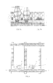
- FIG. 1 is a plane schematic view illustrating an array substrate according to one technique
- FIG. 2 is a cross-sectional schematic view illustrating the liquid crystal display device, and the cross-sectional schematic view is cut along a line of A-A′ in FIG. 1 . As shown in FIG. 1 and FIG.
- the array substrate includes a base substrate 01 , and a buffer layer 02 , an active layer 03 , a gate insulation layer 04 , a gate line layer (including a gate line 05 and a gate electrode G), an inter-layer insulation layer 06 , a data line layer (including a data line 07 , a source electrode S and a drain electrode D), a passivation layer 08 and a via hole 09 provided in the passivation layer 08 , a pixel electrode 010 , an inter-electrode insulation layer 011 and a common electrode 012 , which are sequentially provided on the base substrate 01 .
- each sub-pixel includes a thin film transistor and the pixel electrode.
- the thin film transistor is formed by the active layer 03 , the gate electrode G, the source electrode S and the drain electrode D, and the pixel electrode 010 is connected with the drain electrode D of the thin film transistor through the via hole 09 .
- the opposed substrate includes another base substrate 016 , and a black matrix 013 , a passivation layer 014 and a spacer 015 which are sequentially provided on the base substrate 016 .
- the spacer 015 is provided on the opposed substrate, and a top end thereof abuts on a flat region between adjacent sub-pixels of the array substrate.
- a size of the sub-pixel becomes smaller and smaller; in this case, since there is the via hole 09 , an area of the flat region between adjacent sub-pixels of the array substrate is reduced; if the liquid crystal display device suffers an external force, the spacer 05 may easily slide into the via hole 09 and scratch an alignment layer (not shown) provided on a surface of the array substrate in the process of sliding.
- the spacer 05 slides into the via hole 09 , it is hard to realize a uniform gap between the array substrate and the opposed substrate or maintain uniformity of the thickness of the liquid crystal layer, resulting in uneven displayed image, and decreasing display quality; and in the case that the alignment layer is scratched, abnormal alignment of the liquid crystal molecules in the liquid crystal layer is caused, resulting in light leakage.
- an array substrate comprises: a base substrate; a plurality of gate lines and a plurality of data lines formed on the base substrate, the plurality of gate lines and the plurality of data lines intersecting with each other to define a plurality of sub-pixels, each of the sub-pixels including a thin film transistor and a pixel electrode, and the plurality of sub-pixels including a first sub-pixel; a passivation layer formed on the base substrate and covering the gate lines, the data lines and the thin film transistors, a via hole being provided in the passivation layer and the pixel electrode being formed on the passivation layer and connected with a drain electrode or a source electrode of the thin film transistor through the via hole in each of the sub-pixels; and a first spacer, provided in the via hole of the first sub-pixel.
- the plurality of sub-pixels further include a second sub-pixel; and the array substrate further comprises a second spacer provided in the via hole of the second sub-pixel.
- a height of the first spacer is greater than a height of the second spacer on the base substrate.
- each of the sub-pixels further includes a common electrode and an inter-electrode insulation layer provided between the common electrode and the pixel electrode; the inter-electrode insulation layer has a portion provided on the first spacer but does not have a portion provided on the second spacer, and/or the common electrode has a portion provided on the first spacer but does not have a portion provided on the second spacer.
- a height of the first spacer is equal to a height of the second spacer on the base substrate; each of the sub-pixels further includes a common electrode and an inter-electrode insulation layer provided between the common electrode and the pixel electrode; the inter-electrode insulation layer has a portion provided on the first spacer but does not have a portion provided on the second spacer, and/or the common electrode has a portion provided on the first spacer but does not have a portion provided on the second spacer.
- the array substrate further comprises a third spacer provided above at least one of the gate lines and/or at least one of the data lines.
- the array substrate further comprises a shielding electrode provided on the third spacer.
- each of the sub-pixels further includes a common electrode and an inter-electrode insulation layer provided between the common electrode and the pixel electrode; and the shielding electrode is provided in a same layer with the common electrode.
- each of the sub-pixels further includes a common electrode and an inter-electrode insulation layer provided between the common electrode and the pixel electrode; the inter-electrode insulation layer has a portion provided on the first spacer and the common electrode has a portion provided on the first spacer; the third spacer is provided with a shielding electrode provided in a same layer with the common electrode.
- a display device comprises: an array substrate; an opposed substrate, provided opposite to the array substrate; and a liquid crystal layer, provided between the array substrate and the opposed substrate.
- the array substrate comprises: a base substrate; a plurality of gate lines and a plurality of data lines formed on the base substrate, the plurality of gate lines and the plurality of data lines intersecting with each other to define a plurality of sub-pixels, each of the sub-pixels including a thin film transistor and a pixel electrode, and the plurality of sub-pixels including a first sub-pixel; a passivation layer formed on the base substrate and covering the gate lines, the data lines and the thin film transistors, a via hole being provided in the passivation layer and the pixel electrode being formed on the passivation layer and connected with a drain electrode or a source electrode of the thin film transistor through the via hole in each of the sub-pixels; and a first spacer, provided in the via hole of the first sub-pixel.
- the plurality of sub-pixels further include a second sub-pixel
- the array substrate further comprises a second spacer provided in the via hole of the second sub-pixel.
- a height of the first spacer is greater than a height of the second spacer on the base substrate.
- each of the sub-pixels further includes a common electrode and an inter-electrode insulation layer provided between the common electrode and the pixel electrode; and the inter-electrode insulation layer has a portion provided on the first spacer but does not have a portion provided on the second spacer, and/or the common electrode has a portion provided on the first spacer but does not have a portion provided on the second spacer.
- a height of the first spacer is equal to a height of the second spacer on the base substrate; each of the sub-pixels further includes a common electrode and an inter-electrode insulation layer provided between the common electrode and the pixel electrode; the inter-electrode insulation layer has a portion provided on the first spacer but does not have a portion provided on the second spacer, and/or the common electrode has a portion provided on the first spacer but does not have a portion provided on the second spacer.
- the display device further comprises a third spacer provided above at least one of the gate lines and/or at least one of the data lines.
- the display device further comprises a shielding electrode provided on the third spacer.
- each of the sub-pixels further includes a common electrode and an inter-electrode insulation layer provided between the common electrode and the pixel electrode; and the shielding electrode is provided in a same layer with the common electrode.
- each of the sub-pixels further includes a common electrode and an inter-electrode insulation layer provided between the common electrode and the pixel electrode; the inter-electrode insulation layer has a portion provided on the first spacer and the common electrode has a portion provided on the first spacer; and the third spacer is provided with a shielding electrode provided in a same layer with the common electrode.
- the opposed substrate includes a color filter layer, and the color filter layer has a portion provided above the first spacer.
- a fabrication method of an array substrate comprises: forming a plurality of gate lines and a plurality of data lines on a base substrate, the plurality of gate lines and the plurality of data lines intersecting with each other to define a plurality of sub-pixels, each of the sub-pixels including a thin film transistor and a pixel electrode, and the plurality of sub-pixels including a first sub-pixel; forming a passivation layer covering the gate lines, the data lines and the thin film transistors on the base substrate, a via hole being provided in the passivation layer and the pixel electrode being formed on the passivation layer and connected with a drain electrode or a source electrode of the thin film transistor through the via hole in each of the sub-pixels; and forming a first spacer in the via hole of the first sub-pixel.
- FIG. 1 is a plane schematic view illustrating an array substrate according to one technique
- FIG. 2 a and FIG. 2 b are cross-sectional schematic views illustrating a liquid crystal display device of FIG. 1 , which are cut along a line of A-A′ in FIG. 1 ;
- FIG. 3 is a plane schematic view I illustrating an array substrate according to embodiments of the present disclosure
- FIG. 4 a and FIG. 4 b are cross-sectional schematic views illustrating the array substrate according to the embodiments of the present disclosure, which are cut along a line of A-A′ in FIG. 3 , wherein a height of a first spacer is greater than a height of a second spacer on a base substrate;
- FIG. 5 a and FIG. 5 b are cross-sectional schematic views illustrating the array substrate according to the embodiments of the present disclosure, which are cut along the line of A-A′ in FIG. 3 , wherein the height of the first spacer is equal to the height of the second spacer on the base substrate;
- FIG. 6 is a plane schematic view II illustrating another array substrate according to the embodiments of the present disclosure.
- FIG. 7 a and FIG. 7 b are cross-sectional schematic views illustrating the array substrate according to the embodiments of the present disclosure, which are cut along a line of A-A′ in FIG. 6 , wherein a third spacer is formed;
- FIG. 8 a and FIG. 8 b are cross-sectional schematic views illustrating the array substrate according to the embodiments of the present disclosure, which are cut along the line of A-A′ in FIG. 6 , wherein a height of the first spacer, a height of the second spacer and a height of the third spacer are same on the base substrate;
- FIG. 9 a and FIG. 9 b illustrate a cross-sectional schematic view I of a display device according to the embodiments of the present disclosure
- FIG. 10 a and FIG. 10 b illustrate a cross-sectional schematic view II of the display device according to the embodiments of the present disclosure
- FIG. 11 a and FIG. 11 b illustrate a cross-sectional schematic view III of the display device according to the embodiments of the present disclosure
- FIG. 12 a and FIG. 12 b illustrate a cross-sectional schematic view IV of the display device according to the embodiments of the present disclosure
- FIG. 13 a and FIG. 13 b illustrate a cross-sectional schematic view V of the display device according to the embodiments of the present disclosure
- FIG. 14 a and FIG. 14 b to FIG. 16 a and FIG. 16 b illustrate a flow schematic view I of a fabrication method of an array substrate according to the embodiments of the present disclosure
- FIG. 17 a and FIG. 17 b to FIG. 18 a and FIG. 18 b illustrate a flow schematic view II of the fabrication method of the array substrate according to the embodiments of the present disclosure.
- FIG. 19 a and FIG. 19 b to FIG. 20 a and FIG. 20 b illustrate a flow schematic view III of the fabrication method of the array substrate according to the embodiments of the present disclosure.
- FIG. 3 is a plane schematic view illustrating the array substrate according to the embodiments of the present disclosure
- FIG. 4 a and FIG. 4 b are cross-sectional schematic views cut along a line of A-A′ in FIG. 3 .
- FIG. 3 and FIG. 4 a are cross-sectional schematic views cut along a line of A-A′ in FIG. 3 .
- the array substrate comprises: a base substrate 1 ; a plurality of gate lines 5 and a plurality of data lines 7 formed on the base substrate 1 , the plurality of gate lines 5 and the plurality of data lines 7 intersecting with each other to define a plurality of sub-pixels, each sub-pixel including a thin film transistor and a pixel electrode 10 , and the plurality of sub-pixels including a first sub-pixel; a passivation layer 8 formed on the base substrate 1 and covering the gate lines 5 , the data lines 7 and the thin film transistors, a via hole 9 being provided in the passivation layer and the pixel electrode 10 being formed on the passivation layer 8 and connected with a drain electrode D or a source electrode S of the thin film transistor through the via hole 9 in each sub-pixel; and a first spacer 15 , provided in the via hole of the first sub-pixel.
- an end of the first spacer abuts on the opposed substrate, so that the first spacer is configured for maintaining a uniform gap between the array substrate and the opposed substrate and maintaining uniformity of a thickness of a liquid crystal layer sandwiched between the array substrate and the opposed substrate.
- the first spacer is provided in the via hole of the first sub-pixel. Therefore, even if the display device suffers an external force, the first spacer does not easily slide, and thus situations of nonuniform thickness of the liquid crystal layer and scratches of an alignment layer (not shown in the drawings, the alignment layer is provided on a surface of the array substrate facing the opposed substrate) caused by the first spacer sliding into the via hole are avoided. And thus, the uniform gap between the array substrate and the opposed substrate and the uniformity of the thickness of the liquid crystal layer are maintained well, and light leakage caused by scratches of the alignment layer is avoided, and the display quality is improved.
- the thin film transistor includes an active layer 03 , a gate electrode G, a source electrode S and a drain electrode D; the gate electrode G is connected with the gate line 5 or integrally formed with the gate line 5 , the source electrode S or the drain electrode D is connected with the data line 7 or integrally formed with the data line 7 , and the drain electrode D or the source electrode S is connected with the pixel electrode 10 .
- a buffer layer 2 is formed on the base substrate 1 at first, so as to prevent impurities in the base substrate 1 from entering the active layer 3 and improve the quality of the active layer 3 ; and the active layer 3 , a gate insulation layer 4 , a gate line layer (including the gate line 5 and the gate electrode G), an inter-layer insulation layer 6 , and a data line layer (including the data line 7 , the source electrode S and the drain electrode D) are sequentially formed on the buffer layer 2 .
- the embodiments of the present disclosure are not limited thereto, the array substrate according to the embodiments of the present disclosure may not adopt the buffer layer, and these layers such as the active layer 3 , the gate insulation layer 4 , the gate line layer (including the gate line 5 and the gate electrode G), the inter-layer insulation layer 6 , and the data line layer (including the data line 7 , the source electrode S and the drain electrode D) may be provided in any known stacking sequence. Accordingly, in the array substrate according to the embodiments of the present disclosure, the thin film transistor is of a bottom gate type, a top gate type or any known type.
- the plurality of sub-pixels further include a second sub-pixel, and the second sub-pixel is different from the first sub-pixel described above;
- the array substrate according to the embodiments of the present disclosure further comprises a second spacer 16 , and the second spacer 16 is provided in the via hole 9 of the second sub-pixel.
- a height of the first spacer 15 is greater than a height of the second spacer 16 on the base substrate 1 ; in this case, the first spacer 15 is regarded as a main spacer, and the second spacer 16 is regarded as an assistant spacer.
- the liquid crystal layer contracts at a low temperature so that a volume thereof is reduced. If too many spacers are provided, the opposed substrate is not deformed, and at the low temperature, bubbles are generated in the liquid crystal layer if the display device is suddenly impacted by an external force, resulting in a defect of low temperature bubble.
- the first spacer 15 and the second spacer 16 are provided, and the height of the first spacer 15 is greater than the height of the second spacer 16 , so that not only the defect of low temperature bubble is avoided, but also the defect of pressing is avoided.
- the second spacer 16 is provided in the via hole 9 of the second sub-pixel, the second spacer 16 is prevented from sliding to scratch the alignment layer, and thus abnormal alignment of liquid crystal molecules in the liquid crystal layer and light leakage caused by scratches of the alignment layer are avoided.
- the first spacer 15 and the second spacer 16 are formed by two different patterning processes with using two different single-tone masks.
- the first spacer 15 and the second spacer 16 for example are formed by a single patterning process with using one dual-tone mask.
- each sub-pixel further includes a common electrode 12 and an inter-electrode insulation layer 11 provided between the common electrode 12 and the pixel electrode 10 .
- the inter-electrode insulation layer 11 has a portion provided on the first spacer 15 but does not have a portion provided on the second spacer 15 ; and/or, the common electrode 12 has a portion provided on the first spacer 15 but does not have a portion provided on the second spacer 16 .
- the first spacer 15 and the second spacer 16 for example are formed by the single patterning process with using one dual-tone mask; in order to effectively avoid the defect of low temperature bubble and the defect of pressing, it is necessary to form an enough height difference between the first spacer 15 and the second spacer 16 , which increases technical difficulty in the patterning process of using the dual-tone mask.
- the inter-electrode insulation layer 11 has the portion provided on the first spacer 15 but does not have the portion provided on the second spacer 16 and/or the common electrode 12 has the portion provided on the first spacer 15 but does not have the portion provided on the second spacer 16 , technical requirements on the patterning process of using the dual-tone mask is reduced and flexibility in designs of the first spacer 15 and the second spacer 16 is increased while the defect of low temperature bubble and the defect of pressing are avoided effectively.
- the first spacer 15 and the portion of the inter-electrode insulation layer 11 and/or the portion of the common electrode 12 provided on the spacer 15 are regarded as the main spacer.
- the portion of the inter-electrode insulation layer 11 provided on the first spacer 15 may be disconnected from or connected with other portions of the inter-electrode insulation layer 11
- the portion of the common electrode 12 provided on the first spacer 15 may be disconnected from or connected with other portions of the common electrode 12 .
- both the portion of the inter-electrode insulation layer 11 and the portion of the common electrode 12 are formed on the first spacer 15 ; for example, in the case that the height of the first spacer 15 is greater than the height of the second spacer 16 , neither the portion of the inter-electrode insulation layer 11 or the portion of the common electrode 12 is formed on the first spacer 15 , or only one of the portion of the inter-electrode insulation layer 11 and the portion of the common electrode 12 is formed on the first spacer 15 .
- FIG. 5 a and FIG. 5 b are cross-sectional schematic views illustrating the array substrate according to the embodiments of the present disclosure, which are cut along the line of A-A′ in FIG. 3 .
- the height of the first spacer 15 is equal to the height of the second spacer 16 on the base substrate 1 . Since the height of the first spacer 15 is equal to the height of the second spacer 16 , the first spacer 15 and the second spacer 16 are formed by a single patterning process with using one single-tone mask, which reduces the technical difficulty and technical cost. Further, for example, as shown in FIG. 5 a and FIG.
- the inter-electrode insulation layer 11 has the portion provided on the first spacer 15 but does not have the portion provided on the second spacer 16
- the common electrode 12 has the portion provided on the first spacer 15 but does not have the portion provided on the second spacer 16 , in this way, the defect of low temperature bubble and the defect of pressing are avoided as well.
- the first spacer 15 and the portion of the inter-electrode insulation layer 11 and/or the portion of the common electrode 12 provided on the first spacer 15 are regarded as the main spacer.
- the portion of the inter-electrode insulation layer 11 provided on the first spacer 15 is disconnected from or connected with other portions of the inter-electrode insulation layer 11
- the portion of the common electrode 12 provided on the first spacer 15 is disconnected from or connected with other portions of the common electrode 12 .
- both the portion of the inter-electrode insulation layer 11 and the portion of the common electrode 12 are formed on the first spacer 15 ; for example, in a case that the height of the first spacer 15 is equal to the height of the second spacer 16 , only one of the portion of the inter-electrode insulation layer 11 and the portion of the common electrode 12 is formed on the first spacer 15 .
- neither the first spacer 15 nor the second spacer 16 is provided in the via hole(s) of one or some sub-pixels.
- a ratio of a number of the first spacer 15 to a number of the second spacer 16 is 1:10 to 1:100, and further, for example, is 1:18 or 1:36.
- FIG. 6 is a plane schematic view II of the array substrate according to the embodiments of the present disclosure
- FIG. 7 a and FIG. 7 b are cross-sectional schematic views cut along a line of A-A′ in FIG. 6
- the array substrate according to the embodiments of the present disclosure further comprises a third spacer 17 provided above at least one of the data line 7 and/or at least one of the gate line 5 . Since the third spacer 17 has a certain height, it blocks electric line between adjacent sub-pixels, and thus electric field interference between adjacent sub-pixels is reduced.
- the array substrate according to the embodiments of the present disclosure comprises a display region for arranging the plurality of sub-pixels and a peripheral region surrounding the display region.
- a length of the third spacer 17 is less than or equal to a length of the display region along an extending direction of the third spacer 17 , that is, the third spacer 17 is provided inside the display region.
- the array substrate according to the embodiments of the present disclosure further comprises a shielding electrode 18 provided on the third spacer 17 , so as to further reduce electric field interference between adjacent sub-pixels.
- no voltage is applied to the shielding electrode 18 .
- a voltage is applied to the shielding electrode 18 ; for example, a low level voltage (such as a 0-level voltage) is applied to the shielding electrode 18 .
- the shielding electrode 18 is provided in a same layer with the common electrode 12 , so that the shielding electrode 18 and the common electrode 12 are formed by a single patterning process at the same time, to simplify the fabrication process.
- the shielding electrode 18 is connected with the common electrode 12 , so that a common voltage is applied to the shielding electrode 18 .
- the shielding electrode 18 is disconnected from the common electrode 12 , so that the shielding electrode 18 and the common electrode 12 are driven separately.
- a portion of the inter-electrode insulation layer 11 is further provided between the shielding electrode 18 and the third spacer 17 .
- the portion of the inter-electrode insulation layer 11 provided between the shielding electrode 18 and the third spacer 17 is disconnected from or connected with other portions of the inter-electrode insulation layer 11 .
- the shielding electrode 18 covers an upper surface and a side surface of the third spacer 17 .
- the first spacer 15 , the second spacer 16 and the third spacer 17 are fabricated to have a same height, as shown in FIGS. 8 a and 8 b ; in this case, the first spacer 15 , the second spacer 16 and the third spacer 17 are formed by a single patterning process with using one single-tone mask.
- the inter-electrode insulation layer 11 has the portion provided on the first spacer 15 and the common electrode 12 has the portion provided on the first spacer 15 , and the shielding electrode 18 provided in the same layer with the common electrode 12 is formed on the third spacer 17 ; and therefore, the first spacer 15 and the portion of the inter-electrode insulation layer 11 and the portion of the common electrode 12 provided on the first spacer 15 are regarded as the main spacer, the third spacer 17 and the shielding electrode 18 provided on the third spacer 17 are regarded as a first assistant spacer, the second spacer 16 is regarded as a second assistant spacer, and a height of the main spacer, a height of the first assistant spacer and a height of the second assistant spacer are sequentially reduced, so that the defect of low temperature bubble and the defect of pressing are more effectively avoided.
- the base substrate 1 , the buffer layer 2 , the active layer 3 , the gate insulation layer 4 , the gate line layer (including the gate line 5 and the gate electrode G), the inter-layer insulation layer 6 , the data line layer (including the data line 7 , the source electrode S and the drain electrode D), the passivation layer 8 , the pixel electrode 10 , the inter-electrode insulation layer 11 and the common electrode 12 may be made of any known material or formed by any known method, which will not be repeated here.
- the active layer 3 is made of a low temperature polysilicon.
- the passivation layer 8 is made of an organic resin, for example, an acrylic resin.
- the spacer (such as the first spacer 15 , the second spacer 16 and the third spacer 17 ) is made of an organic resin, for example, a negative PR adhesive.
- the first spacer 15 , the second spacer 16 and the third spacer 17 are made of a same material or different materials.
- first spacer 15 and the second spacer 16 formed in the via hole 9 are in direct contact with the pixel electrode 10 formed in the via hole 9 ; however, the embodiments of the present disclosure are not limited thereto, an inserting layer may be formed between the first spacer 15 and the pixel electrode 10 and/or between the second spacer 16 and the pixel electrode 10 according to actual needs.
- a display device comprises: the array substrate described above; an opposed substrate, provided opposite to the array substrate, wherein an end of the first spacer abuts on the opposed substrate; and a liquid crystal layer, provided between the array substrate and the opposed substrate. Since the display device according to the embodiments of the present disclosure comprises the array substrate described above, even if the display device is under action of an external force, the first spacer is not easily slide, and thus situations of nonuniform thickness of the liquid crystal layer and scratches of the alignment layer (not shown, which is provided on a surface of the array substrate facing the opposed substrate) caused by the first spacer sliding into the via hole are avoided. And thus, the uniform gap between the array substrate and the opposed substrate is realized, the uniformity in the thickness of the liquid crystal layer is maintained well, the light leakage caused by scratches of the alignment layer is avoided, and the display quality is improved.
- FIGS. 9 a and 9 b , FIGS. 10 a and 10 b , FIGS. 11 a and 11 b , FIGS. 12 a and 12 b , and FIGS. 13 a and 13 b are cross-sectional schematic views illustrating the display device according to the embodiments of the present disclosure.
- the opposed substrate includes a base substrate 20 , and a black matrix 13 and a passivation layer 14 which are sequentially provided on the base substrate 20 ; the first spacer 15 , the second spacer 16 and the third spacer 17 as described above are all provided in a region covered by the black matrix 13 .
- the display device shown in FIGS. 9 a and 9 b adopts the array substrate shown in FIGS. 4 a and 4 b
- the display device shown in FIGS. 10 a and 10 b adopts the array substrate shown in FIGS. 5 a and 5 b
- the display device shown in FIGS. 11 a and 11 b adopts the array substrate shown in FIGS. 7 a and 7 b
- the display device shown in FIGS. 12 a and 12 b adopts the array substrate shown in FIGS. 8 a and 8 b , which will not be repeated here.
- the display device shown in FIGS. 13 a and 13 b is almost same as the display device shown in FIGS. 9 a and 9 b .
- the opposed substrate further includes a color filter layer 19 .
- the color filter layer 19 has a portion provided above the first spacer 15 but does not have a portion provided above the second spacer 16 , which is also conducive to avoiding the defect of low temperature bubble and the defect of pressing and further reduce technical requirements on a patterning process of using the dual-tone mask and increase flexibility in designs of the first spacer 15 and the second spacer 16 .
- the opposed substrate shown in FIGS. 13 a and 13 b may replace the opposed substrate shown in FIGS. 10 a and 10 b , FIGS. 11 a and 11 b , and FIGS. 12 a and 12 b.
- the display device is any product or component having a display function, such as a liquid crystal display panel, a liquid crystal display device, a mobile phone, a tablet PC, a TV, a monitor, a laptop computer, a digital photo frame, a navigator, etc.
- a display function such as a liquid crystal display panel, a liquid crystal display device, a mobile phone, a tablet PC, a TV, a monitor, a laptop computer, a digital photo frame, a navigator, etc.
- the fabrication method of the array substrate comprises: forming a plurality of gate lines 5 and a plurality of data lines 7 on a base substrate 1 , the plurality of gate lines 5 and the plurality of data lines 7 intersecting with each other to define a plurality of sub-pixels, each sub-pixel including a thin film transistor and a pixel electrode 10 , and the plurality of sub-pixels including a first sub-pixel; forming a passivation layer 8 covering the gate lines 5 , the data lines 7 and the thin film transistors on the base substrate 1 , a via hole being provided in the passivation layer 8 and the pixel electrode 10 being formed on the passivation layer 8 and connected with a drain electrode D or a source electrode S of the thin film transistor through the via hole 9 in the each sub-pixel; and forming a first spacer 15 in the via hole of the first sub-pixel 9 .
- the first spacer is formed in the via hole of the first sub-pixel. And thus, even if a display device formed by bonding the array substrate and an opposed substrate is under action of external forces, the first spacer is not easily slide, so that situations of nonuniform thickness of the liquid crystal layer and scratches of an alignment layer (not shown, which is provided on a surface of the array substrate facing the opposed substrate) caused by the first spacer sliding into the via hole are avoided. And thus, a uniform gap between the array substrate and the opposed substrate and uniformity of a thickness of the liquid crystal layer are maintained well, and a light leakage caused by scratches of the alignment layer is avoided, and a display quality is improved.
- the plurality of sub-pixels further include a second sub-pixel
- the fabrication method of the array substrate further comprises: forming a second spacer 16 in the via hole 9 of the second sub-pixel.
- FIGS. 14 a and 14 b to FIGS. 16 a and 16 b show a flow schematic view I of the fabrication method of the array substrate according to the embodiments of the present disclosure.
- a buffer layer 2 is formed on a base substrate 1 , and an active layer 3 , a gate insulation layer 4 , a gate line layer (including the gate line 5 and a gate electrode G), an inter-layer insulation layer 6 , a data line layer (including the data line 7 , the source electrode S and the drain electrode D), the passivation layer 8 and the via hole 9 , and the pixel electrode 10 are sequentially formed on the buffer layer.
- the thin film transistor is formed by the active layer 3 , the gate electrode G, the source electrode S and the drain electrode D, and the pixel electrode 10 is connected with the drain electrode D or the source electrode S of the thin film transistor through the via hole 9 provided in the passivation layer 8 .
- the respective layers described above may be made of any known materials or formed by any known methods, which will not be repeated here.
- the sequence for stacking the respective layers described above is not limited to the sequence shown in FIGS. 14 a and 14 b , and may be adjusted according to actual needs, which will not be repeated here.
- a material layer for forming the spacer (for example, such material layer for forming the spacer is formed by a photoresist adhesive and has a thickness of 4 to 6 ⁇ m) is formed, and the material layer for forming the spacer is patterned by using a dual-tone mask (such as, a half-tone mask and a gray-tone mask), to form the first spacer 15 and the second spacer 16 by a single patterning process at the same time, and a height of the first spacer 15 is greater than a height of the second spacer 16 , as shown in FIGS. 15 a and 15 b .
- a dual-tone mask such as, a half-tone mask and a gray-tone mask
- the fabrication method of the array substrate further comprises: forming an inter-electrode insulation layer 11 on the pixel electrode 10 , and the inter-electrode insulation layer 11 has a portion provided on the first spacer 15 but does not have a portion provided on the second spacer 16 , as shown in FIGS. 16 a and 16 b .
- the fabrication method of the array substrate further comprises: forming a common electrode 12 on the inter-electrode insulation layer 11 , and the common electrode 12 has a portion provided on the first spacer 15 but does not have a portion provided on the second spacer 16 , and thus the array substrate shown in FIGS. 4 a and 4 b is obtained.
- FIGS. 17 a and 17 b to FIGS. 18 a and 18 b show a flow schematic view II of the fabrication method of the array substrate according to the embodiments of the present disclosure.
- the material layer for forming the spacer (for example, the material layer for forming the spacer is formed by the photoresist adhesive and has a thickness of 4 to 6 ⁇ m) is formed, and the material layer for forming the spacer is patterned by using a single-tone mask, to form the first spacer 15 and the second spacer 16 by a single patterning process at the same time, and the height of the first spacer 15 is equal to the height of the second spacer 16 , as shown in FIGS.
- the fabrication method of the array substrate further comprises: forming the inter-electrode insulation layer 11 on the pixel electrode 10 , and the inter-electrode insulation layer 11 has the portion provided on the first spacer 15 but does not have the portion provided on the second spacer 16 , as shown in FIGS. 18 a and 18 b .
- the fabrication method of the array substrate further comprises: forming the common electrode 12 on the inter-electrode insulation layer 11 , and the common electrode 12 has the portion provided on the first spacer 15 but does not have the portion provided on the second spacer 16 , and thus the array substrate shown in FIGS. 5 a and 5 b is obtained.
- FIG. 19 a and FIG. 19 b to FIG. 20 a and FIG. 20 b show a flow schematic view III of the fabrication method of the array substrate according to the embodiments of the present disclosure.
- the first spacer 15 , the second spacer 16 and a third spacer 17 are formed, as shown in FIGS. 19 a and 19 b .
- the first spacer 15 , the second spacer 16 and the third spacer 17 are formed by three different patterning processes by using three different masks.
- the first spacer 15 and the second spacer 16 are formed by a single patterning process with using one dual-tone mask, and then the third spacer 17 is formed by a single patterning process with using one single-tone mask.
- the first spacer 15 , the second spacer 16 and the third spacer 17 are fabricated to have a same height; in this way, the first spacer 15 , the second spacer 16 and the third spacer 17 are formed by a single patterning process with using one single-tone mask.
- the fabrication method of the array substrate further comprises: forming the inter-electrode insulation layer 11 on the pixel electrode 10 , and the inter-electrode insulation layer 11 has the portion provided on the first spacer 15 but does not have the portion provided on the second spacer 16 , as shown in FIGS. 20 a and 20 b .
- the fabrication method of the array substrate further comprises: forming the common electrode 12 on the inter-electrode insulation layer 11 , and the common electrode 12 has the portion provided on the first spacer 15 but does not have the portion provided on the second spacer 16 .
- the fabrication method of the array substrate further comprises: forming a shielding electrode 18 on the third spacer 17 , and thus the array substrate shown in FIGS. 7 a and 7 b is obtained.
- the common electrode 12 and the shielding electrode 18 are formed by patterning a common electrode material layer at the same time.
Landscapes
- Physics & Mathematics (AREA)
- Nonlinear Science (AREA)
- Mathematical Physics (AREA)
- Chemical & Material Sciences (AREA)
- Crystallography & Structural Chemistry (AREA)
- General Physics & Mathematics (AREA)
- Optics & Photonics (AREA)
- Engineering & Computer Science (AREA)
- Microelectronics & Electronic Packaging (AREA)
- Liquid Crystal (AREA)
- Geometry (AREA)
- Devices For Indicating Variable Information By Combining Individual Elements (AREA)
Abstract
Description
Claims (16)
Applications Claiming Priority (4)
| Application Number | Priority Date | Filing Date | Title |
|---|---|---|---|
| CN201510346651.0 | 2015-06-19 | ||
| CN201510346651.0A CN104880878B (en) | 2015-06-19 | 2015-06-19 | Array substrate, manufacturing method thereof, and display device |
| CN201510346651 | 2015-06-19 | ||
| PCT/CN2015/094583 WO2016201874A1 (en) | 2015-06-19 | 2015-11-13 | Array substrate and method for manufacturing same, and display device |
Publications (2)
| Publication Number | Publication Date |
|---|---|
| US20170146844A1 US20170146844A1 (en) | 2017-05-25 |
| US10025143B2 true US10025143B2 (en) | 2018-07-17 |
Family
ID=53948430
Family Applications (1)
| Application Number | Title | Priority Date | Filing Date |
|---|---|---|---|
| US15/110,230 Active 2036-01-23 US10025143B2 (en) | 2015-06-19 | 2015-11-13 | Array substrate and fabrication method thereof, and display device |
Country Status (4)
| Country | Link |
|---|---|
| US (1) | US10025143B2 (en) |
| EP (1) | EP3312668B1 (en) |
| CN (1) | CN104880878B (en) |
| WO (1) | WO2016201874A1 (en) |
Cited By (1)
| Publication number | Priority date | Publication date | Assignee | Title |
|---|---|---|---|---|
| US12276890B2 (en) | 2022-01-14 | 2025-04-15 | Boe Technology Group Co., Ltd. | Display panel having support structures being formed in via holes of the interlayer insulating layer |
Families Citing this family (14)
| Publication number | Priority date | Publication date | Assignee | Title |
|---|---|---|---|---|
| CN104880878B (en) * | 2015-06-19 | 2019-10-15 | 京东方科技集团股份有限公司 | Array substrate, manufacturing method thereof, and display device |
| WO2017145943A1 (en) * | 2016-02-24 | 2017-08-31 | シャープ株式会社 | Active matrix substrate and liquid crystal display device |
| CN105629615A (en) * | 2016-04-01 | 2016-06-01 | 京东方科技集团股份有限公司 | Array substrate and manufacture method thereof, display panel and display device |
| CN105870132A (en) * | 2016-04-18 | 2016-08-17 | 武汉华星光电技术有限公司 | TFT (thin film transistor) array substrate and manufacturing method therefor |
| CN107479264A (en) * | 2017-09-25 | 2017-12-15 | 惠科股份有限公司 | Display panel and display device |
| CN107741673B (en) * | 2017-10-13 | 2019-08-16 | 深圳市华星光电半导体显示技术有限公司 | The preparation method and liquid crystal display panel of a kind of spacer in liquid crystal display panel |
| US20190155091A1 (en) * | 2017-11-22 | 2019-05-23 | Shenzhen China Star Optoelectronics Semiconductor Display Technology Co., Ltd. | Tft array substrate, manufacturing method and liquid crystal display panel |
| CN109637362B (en) * | 2019-01-31 | 2021-07-09 | 厦门天马微电子有限公司 | Display panel and display device |
| US11415838B2 (en) * | 2019-11-06 | 2022-08-16 | Innolux Corporation | Display device |
| KR102740407B1 (en) * | 2020-03-24 | 2024-12-10 | 보에 테크놀로지 그룹 컴퍼니 리미티드 | Array substrate, display device, and method for manufacturing array substrate |
| CN111769124A (en) * | 2020-07-27 | 2020-10-13 | 成都中电熊猫显示科技有限公司 | Manufacturing method of metal oxide array substrate, array substrate and display panel |
| CN116487388A (en) | 2022-01-14 | 2023-07-25 | 京东方科技集团股份有限公司 | Array substrate and display panel |
| CN115236902B (en) * | 2022-06-16 | 2023-11-28 | 京东方科技集团股份有限公司 | Array substrate, liquid crystal display panel and liquid crystal display device |
| CN117148632A (en) * | 2023-08-30 | 2023-12-01 | 厦门天马微电子有限公司 | Array substrate and display panel |
Citations (17)
| Publication number | Priority date | Publication date | Assignee | Title |
|---|---|---|---|---|
| US20020012083A1 (en) * | 2000-07-28 | 2002-01-31 | Jun Tanaka | Color liquid crystal panel and color liquid crystal display apparatus |
| US20040223109A1 (en) * | 2003-03-28 | 2004-11-11 | Fujitsu Display Technologies Corporation | Liquid crystal panel and method of manufacturing the same |
| KR20080034545A (en) | 2006-10-17 | 2008-04-22 | 삼성전자주식회사 | Liquid Crystal Display and Manufacturing Method Thereof |
| CN101587265A (en) | 2008-05-23 | 2009-11-25 | 上海广电Nec液晶显示器有限公司 | Liquid crystal display device and manufacture method thereof |
| US20100007837A1 (en) * | 2008-07-08 | 2010-01-14 | Samsung Electronics Co.,Ltd. | Array substrate and liquid crystal display apparatus having the same |
| US20110102698A1 (en) * | 2009-11-03 | 2011-05-05 | Wintek Corporation | Liquid crystal display panel |
| CN102073171A (en) | 2009-11-23 | 2011-05-25 | 三星电子株式会社 | Liquid crystal display |
| US20110156039A1 (en) * | 2009-12-30 | 2011-06-30 | Samsung Electronics Co., Ltd. | Display apparatus and method for manufacturing the same |
| CN102346340A (en) | 2010-08-03 | 2012-02-08 | 胜华科技股份有限公司 | Liquid crystal display panel |
| CN102955297A (en) | 2012-10-22 | 2013-03-06 | 京东方科技集团股份有限公司 | Liquid crystal display panel and manufacturing method thereof |
| US20130222723A1 (en) * | 2012-02-27 | 2013-08-29 | Lg Display Co., Ltd. | Liquid crystal display device and method for fabricating the same |
| US20130234143A1 (en) * | 2012-03-08 | 2013-09-12 | Jeongwoo HWANG | Liquid crystal display array substrate and method for manufacturing the same |
| KR20140098964A (en) * | 2013-01-31 | 2014-08-11 | 엘지디스플레이 주식회사 | Liquid display panel and method of fabricating the same |
| US20150002774A1 (en) * | 2013-06-28 | 2015-01-01 | Lg Display Co., Ltd. | Liquid crystal polymer composition, liquid crystal display and method for manufacturing the same |
| CN104375331A (en) | 2014-11-21 | 2015-02-25 | 厦门天马微电子有限公司 | Liquid crystal display device and manufacturing method thereof |
| CN104656320A (en) | 2015-03-23 | 2015-05-27 | 合肥京东方光电科技有限公司 | Liquid crystal display panel and display device |
| CN104880878A (en) | 2015-06-19 | 2015-09-02 | 京东方科技集团股份有限公司 | Array substrate, manufacturing method thereof and display device |
Family Cites Families (2)
| Publication number | Priority date | Publication date | Assignee | Title |
|---|---|---|---|---|
| JP2009169162A (en) * | 2008-01-17 | 2009-07-30 | Epson Imaging Devices Corp | Liquid crystal display |
| KR101820533B1 (en) * | 2011-08-02 | 2018-01-22 | 엘지디스플레이 주식회사 | Fringe field switching liquid crystal display device and method of fabricating the same |
-
2015
- 2015-06-19 CN CN201510346651.0A patent/CN104880878B/en active Active
- 2015-11-13 EP EP15874424.3A patent/EP3312668B1/en active Active
- 2015-11-13 WO PCT/CN2015/094583 patent/WO2016201874A1/en not_active Ceased
- 2015-11-13 US US15/110,230 patent/US10025143B2/en active Active
Patent Citations (19)
| Publication number | Priority date | Publication date | Assignee | Title |
|---|---|---|---|---|
| US20020012083A1 (en) * | 2000-07-28 | 2002-01-31 | Jun Tanaka | Color liquid crystal panel and color liquid crystal display apparatus |
| US20040223109A1 (en) * | 2003-03-28 | 2004-11-11 | Fujitsu Display Technologies Corporation | Liquid crystal panel and method of manufacturing the same |
| KR20080034545A (en) | 2006-10-17 | 2008-04-22 | 삼성전자주식회사 | Liquid Crystal Display and Manufacturing Method Thereof |
| CN101587265A (en) | 2008-05-23 | 2009-11-25 | 上海广电Nec液晶显示器有限公司 | Liquid crystal display device and manufacture method thereof |
| US20100007837A1 (en) * | 2008-07-08 | 2010-01-14 | Samsung Electronics Co.,Ltd. | Array substrate and liquid crystal display apparatus having the same |
| US20110102698A1 (en) * | 2009-11-03 | 2011-05-05 | Wintek Corporation | Liquid crystal display panel |
| US20150002775A1 (en) * | 2009-11-23 | 2015-01-01 | Samsung Display Co., Ltd. | Liquid crystal display |
| CN102073171A (en) | 2009-11-23 | 2011-05-25 | 三星电子株式会社 | Liquid crystal display |
| US20110122357A1 (en) * | 2009-11-23 | 2011-05-26 | Samsung Electronics Co., Ltd. | Liquid crystal display |
| US20110156039A1 (en) * | 2009-12-30 | 2011-06-30 | Samsung Electronics Co., Ltd. | Display apparatus and method for manufacturing the same |
| CN102346340A (en) | 2010-08-03 | 2012-02-08 | 胜华科技股份有限公司 | Liquid crystal display panel |
| US20130222723A1 (en) * | 2012-02-27 | 2013-08-29 | Lg Display Co., Ltd. | Liquid crystal display device and method for fabricating the same |
| US20130234143A1 (en) * | 2012-03-08 | 2013-09-12 | Jeongwoo HWANG | Liquid crystal display array substrate and method for manufacturing the same |
| CN102955297A (en) | 2012-10-22 | 2013-03-06 | 京东方科技集团股份有限公司 | Liquid crystal display panel and manufacturing method thereof |
| KR20140098964A (en) * | 2013-01-31 | 2014-08-11 | 엘지디스플레이 주식회사 | Liquid display panel and method of fabricating the same |
| US20150002774A1 (en) * | 2013-06-28 | 2015-01-01 | Lg Display Co., Ltd. | Liquid crystal polymer composition, liquid crystal display and method for manufacturing the same |
| CN104375331A (en) | 2014-11-21 | 2015-02-25 | 厦门天马微电子有限公司 | Liquid crystal display device and manufacturing method thereof |
| CN104656320A (en) | 2015-03-23 | 2015-05-27 | 合肥京东方光电科技有限公司 | Liquid crystal display panel and display device |
| CN104880878A (en) | 2015-06-19 | 2015-09-02 | 京东方科技集团股份有限公司 | Array substrate, manufacturing method thereof and display device |
Non-Patent Citations (2)
| Title |
|---|
| International Search Report and Written Opinion dated Mar. 17, 2016; PCT/CN2015/094583. |
| The First Chinese Office Action dated May 26, 2017; Appln. No. 201510346651.0. |
Cited By (1)
| Publication number | Priority date | Publication date | Assignee | Title |
|---|---|---|---|---|
| US12276890B2 (en) | 2022-01-14 | 2025-04-15 | Boe Technology Group Co., Ltd. | Display panel having support structures being formed in via holes of the interlayer insulating layer |
Also Published As
| Publication number | Publication date |
|---|---|
| US20170146844A1 (en) | 2017-05-25 |
| EP3312668B1 (en) | 2021-10-13 |
| CN104880878A (en) | 2015-09-02 |
| WO2016201874A1 (en) | 2016-12-22 |
| CN104880878B (en) | 2019-10-15 |
| EP3312668A1 (en) | 2018-04-25 |
| EP3312668A4 (en) | 2019-01-16 |
Similar Documents
| Publication | Publication Date | Title |
|---|---|---|
| US10025143B2 (en) | Array substrate and fabrication method thereof, and display device | |
| US9638975B2 (en) | Method for manufacturing COA liquid crystal panel comprising color resist blocks having first and second intersection zones and COA liquid crystal panel | |
| US20130050619A1 (en) | Display apparatus and method for manufacturing the same | |
| US10481452B2 (en) | Display panel | |
| US10838262B2 (en) | Liquid crystal display device and mother substrate | |
| US20130120679A1 (en) | Liquid crystal panel and manufacturing method thereof, and liquid crystal display device | |
| US11269221B2 (en) | Display panel and display apparatus | |
| US20190027498A1 (en) | Array substrate and display device | |
| US20170255068A1 (en) | Liquid crystal panel | |
| JP2019525256A (en) | Liquid crystal display panel and liquid crystal display device | |
| US20160005347A1 (en) | Display panel | |
| US10168570B2 (en) | Display apparatus | |
| US10197868B2 (en) | Display device and method of manufacturing the same | |
| US9915846B2 (en) | Array substrate and display device | |
| US12164187B2 (en) | Display substrate and display panel in each of which distance from convex structure to a substrate and distance from alignment layer to the substrate has preset difference therebetween | |
| US9568777B2 (en) | Display substrate, preparing method thereof, and display device | |
| US10634956B2 (en) | Display panel and display device | |
| CN109270751B (en) | Array substrate and liquid crystal display panel | |
| US9927645B2 (en) | Curved display device | |
| US10180610B2 (en) | Thin film transistor array substrate and manufacturing method thereof, and display device | |
| CN207337023U (en) | Display panel and display device | |
| KR100687351B1 (en) | LCD Display | |
| JP6121508B2 (en) | Liquid crystal display device and manufacturing method thereof | |
| KR20160057228A (en) | Color filter on thin film transistor structure liquid crystal display device | |
| JP2017122937A (en) | Liquid crystal display |
Legal Events
| Date | Code | Title | Description |
|---|---|---|---|
| AS | Assignment |
Owner name: CHENGDU BOE OPTOELECTRONICS TECHNOLOGY CO., LTD., Free format text: ASSIGNMENT OF ASSIGNORS INTEREST;ASSIGNOR:XIN, YANXIA;REEL/FRAME:039277/0570 Effective date: 20160504 Owner name: BOE TECHNOLOGY GROUP CO., LTD., CHINA Free format text: ASSIGNMENT OF ASSIGNORS INTEREST;ASSIGNOR:XIN, YANXIA;REEL/FRAME:039277/0570 Effective date: 20160504 Owner name: CHENGDU BOE OPTOELECTRONICS TECHNOLOGY CO., LTD., Free format text: ASSIGNMENT OF ASSIGNORS INTEREST;ASSIGNOR:MOU, XUN;REEL/FRAME:039277/0767 Effective date: 20160504 Owner name: CHENGDU BOE OPTOELECTRONICS TECHNOLOGY CO., LTD., Free format text: ASSIGNMENT OF ASSIGNORS INTEREST;ASSIGNOR:YANG, YUQING;REEL/FRAME:039277/0561 Effective date: 20160504 Owner name: CHENGDU BOE OPTOELECTRONICS TECHNOLOGY CO., LTD., Free format text: ASSIGNMENT OF ASSIGNORS INTEREST;ASSIGNOR:YANG, XIAOFEI;REEL/FRAME:039277/0555 Effective date: 20160504 Owner name: BOE TECHNOLOGY GROUP CO., LTD., CHINA Free format text: ASSIGNMENT OF ASSIGNORS INTEREST;ASSIGNOR:JIANG, XUE;REEL/FRAME:039277/0678 Effective date: 20160504 Owner name: CHENGDU BOE OPTOELECTRONICS TECHNOLOGY CO., LTD., Free format text: ASSIGNMENT OF ASSIGNORS INTEREST;ASSIGNOR:MO, ZAILONG;REEL/FRAME:039277/0598 Effective date: 20160504 Owner name: BOE TECHNOLOGY GROUP CO., LTD., CHINA Free format text: ASSIGNMENT OF ASSIGNORS INTEREST;ASSIGNOR:YANG, XIAOFEI;REEL/FRAME:039277/0555 Effective date: 20160504 Owner name: CHENGDU BOE OPTOELECTRONICS TECHNOLOGY CO., LTD., Free format text: ASSIGNMENT OF ASSIGNORS INTEREST;ASSIGNOR:JIANG, XUE;REEL/FRAME:039277/0678 Effective date: 20160504 Owner name: BOE TECHNOLOGY GROUP CO., LTD., CHINA Free format text: ASSIGNMENT OF ASSIGNORS INTEREST;ASSIGNOR:MOU, XUN;REEL/FRAME:039277/0767 Effective date: 20160504 Owner name: BOE TECHNOLOGY GROUP CO., LTD., CHINA Free format text: ASSIGNMENT OF ASSIGNORS INTEREST;ASSIGNOR:MO, ZAILONG;REEL/FRAME:039277/0598 Effective date: 20160504 Owner name: BOE TECHNOLOGY GROUP CO., LTD., CHINA Free format text: ASSIGNMENT OF ASSIGNORS INTEREST;ASSIGNOR:YANG, YUQING;REEL/FRAME:039277/0561 Effective date: 20160504 |
|
| STCF | Information on status: patent grant |
Free format text: PATENTED CASE |
|
| MAFP | Maintenance fee payment |
Free format text: PAYMENT OF MAINTENANCE FEE, 4TH YEAR, LARGE ENTITY (ORIGINAL EVENT CODE: M1551); ENTITY STATUS OF PATENT OWNER: LARGE ENTITY Year of fee payment: 4 |
|
| FEPP | Fee payment procedure |
Free format text: MAINTENANCE FEE REMINDER MAILED (ORIGINAL EVENT CODE: REM.); ENTITY STATUS OF PATENT OWNER: LARGE ENTITY |