US10024435B2 - Seal assembly with biasing member retaining pockets - Google Patents
Seal assembly with biasing member retaining pockets Download PDFInfo
- Publication number
- US10024435B2 US10024435B2 US15/157,863 US201615157863A US10024435B2 US 10024435 B2 US10024435 B2 US 10024435B2 US 201615157863 A US201615157863 A US 201615157863A US 10024435 B2 US10024435 B2 US 10024435B2
- Authority
- US
- United States
- Prior art keywords
- seal
- retaining
- seals
- coupling
- Prior art date
- Legal status (The legal status is an assumption and is not a legal conclusion. Google has not performed a legal analysis and makes no representation as to the accuracy of the status listed.)
- Active
Links
Images




Classifications
-
- F—MECHANICAL ENGINEERING; LIGHTING; HEATING; WEAPONS; BLASTING
- F16—ENGINEERING ELEMENTS AND UNITS; GENERAL MEASURES FOR PRODUCING AND MAINTAINING EFFECTIVE FUNCTIONING OF MACHINES OR INSTALLATIONS; THERMAL INSULATION IN GENERAL
- F16J—PISTONS; CYLINDERS; SEALINGS
- F16J15/00—Sealings
- F16J15/44—Free-space packings
- F16J15/441—Free-space packings with floating ring
- F16J15/442—Free-space packings with floating ring segmented
-
- F—MECHANICAL ENGINEERING; LIGHTING; HEATING; WEAPONS; BLASTING
- F16—ENGINEERING ELEMENTS AND UNITS; GENERAL MEASURES FOR PRODUCING AND MAINTAINING EFFECTIVE FUNCTIONING OF MACHINES OR INSTALLATIONS; THERMAL INSULATION IN GENERAL
- F16J—PISTONS; CYLINDERS; SEALINGS
- F16J15/00—Sealings
- F16J15/16—Sealings between relatively-moving surfaces
- F16J15/34—Sealings between relatively-moving surfaces with slip-ring pressed against a more or less radial face on one member
- F16J15/3436—Pressing means
-
- F—MECHANICAL ENGINEERING; LIGHTING; HEATING; WEAPONS; BLASTING
- F16—ENGINEERING ELEMENTS AND UNITS; GENERAL MEASURES FOR PRODUCING AND MAINTAINING EFFECTIVE FUNCTIONING OF MACHINES OR INSTALLATIONS; THERMAL INSULATION IN GENERAL
- F16J—PISTONS; CYLINDERS; SEALINGS
- F16J15/00—Sealings
- F16J15/16—Sealings between relatively-moving surfaces
- F16J15/32—Sealings between relatively-moving surfaces with elastic sealings, e.g. O-rings
- F16J15/3204—Sealings between relatively-moving surfaces with elastic sealings, e.g. O-rings with at least one lip
- F16J15/3208—Sealings between relatively-moving surfaces with elastic sealings, e.g. O-rings with at least one lip provided with tension elements, e.g. elastic rings
- F16J15/3212—Sealings between relatively-moving surfaces with elastic sealings, e.g. O-rings with at least one lip provided with tension elements, e.g. elastic rings with metal springs
-
- F—MECHANICAL ENGINEERING; LIGHTING; HEATING; WEAPONS; BLASTING
- F16—ENGINEERING ELEMENTS AND UNITS; GENERAL MEASURES FOR PRODUCING AND MAINTAINING EFFECTIVE FUNCTIONING OF MACHINES OR INSTALLATIONS; THERMAL INSULATION IN GENERAL
- F16J—PISTONS; CYLINDERS; SEALINGS
- F16J15/00—Sealings
- F16J15/16—Sealings between relatively-moving surfaces
- F16J15/32—Sealings between relatively-moving surfaces with elastic sealings, e.g. O-rings
- F16J15/3204—Sealings between relatively-moving surfaces with elastic sealings, e.g. O-rings with at least one lip
- F16J15/3208—Sealings between relatively-moving surfaces with elastic sealings, e.g. O-rings with at least one lip provided with tension elements, e.g. elastic rings
-
- F—MECHANICAL ENGINEERING; LIGHTING; HEATING; WEAPONS; BLASTING
- F16—ENGINEERING ELEMENTS AND UNITS; GENERAL MEASURES FOR PRODUCING AND MAINTAINING EFFECTIVE FUNCTIONING OF MACHINES OR INSTALLATIONS; THERMAL INSULATION IN GENERAL
- F16J—PISTONS; CYLINDERS; SEALINGS
- F16J15/00—Sealings
- F16J15/16—Sealings between relatively-moving surfaces
- F16J15/34—Sealings between relatively-moving surfaces with slip-ring pressed against a more or less radial face on one member
- F16J15/3436—Pressing means
- F16J15/3452—Pressing means the pressing force resulting from the action of a spring
-
- F—MECHANICAL ENGINEERING; LIGHTING; HEATING; WEAPONS; BLASTING
- F16—ENGINEERING ELEMENTS AND UNITS; GENERAL MEASURES FOR PRODUCING AND MAINTAINING EFFECTIVE FUNCTIONING OF MACHINES OR INSTALLATIONS; THERMAL INSULATION IN GENERAL
- F16J—PISTONS; CYLINDERS; SEALINGS
- F16J15/00—Sealings
- F16J15/16—Sealings between relatively-moving surfaces
- F16J15/34—Sealings between relatively-moving surfaces with slip-ring pressed against a more or less radial face on one member
- F16J15/3464—Mounting of the seal
Definitions
- the present invention relates to circumferential shaft seals, and more particularly to the structure for axially-biasing tandem circumferential shaft seals.
- Double or “tandem” circumferential shaft seals are known and include two axially spaced seals disposed within a common housing. Each seal has an inner circumferential surface sealing engageable with the outer circumferential surface of a rotatable shaft. In order to maintain axial spacing between the two seals, a plurality of biasing members, such as coil springs, extending between the two seals are typically provided.
- the present invention is a seal assembly for sealing about a shaft rotatable about a central axis and having an outer circumferential surface.
- the seal assembly comprises first and second generally annular seals disposable about the shaft so as to be spaced apart axially along the shaft central axis.
- Each one of the two seals has an inner circumferential surface for sealing about the shaft outer surface and opposing inner and outer axial sides, and each seal inner axial side faces the other seal inner axial side.
- the first seal has at least one coupling pocket extending generally axially inwardly from the first seal inner axial side and the second seal has a retaining pocket extending generally axially inwardly from the second seal inner axial side.
- the retaining pocket is generally aligned with the coupling pocket.
- At least one biasing member has a first end disposed within the at least one coupling pocket and an opposing, second end disposed within the at least one retaining pocket.
- the biasing member is configured to exert a generally axial biasing force on each one of the first and second seals.
- the present invention is again a seal assembly for sealing about a shaft rotatable about a central axis and having an outer circumferential surface.
- the seal assembly comprises first and second generally annular seals disposable about the shaft so as to be spaced apart axially along the shaft central axis.
- Each one of the two seals has an inner circumferential surface for sealing about the shaft outer surface and opposing inner and outer axial sides and each seal inner axial side facing the other seal inner axial side.
- the first seal has at least one spring coupling pocket extending generally axially inwardly from the first seal inner axial side and having a radial length.
- the second seal has a spring retaining pocket extending generally axially inwardly from the second seal inner axial side and having a radial length substantially greater than the coupling pocket radial length, the retaining pocket being generally aligned with the coupling pocket.
- the assembly includes at least one spring having a first end disposed within the at least one coupling pocket and an opposing, second end disposed within the at least one retaining pocket.
- the spring is configured to exert a generally axial biasing force on each one of the first and second seals.
- the spring second end is generally radially displaceable within the retaining pocket when at least one of the first and second seals radially displaces relative to the other one of the first and second seals.
- FIG. 1 is a broken-away, axial cross-sectional view of a seal assembly in accordance with the present invention, shown disposed about a shaft and located within a housing;
- FIG. 2 is an axial cross-sectional view of the seal assembly separate from the shaft and housing;
- FIG. 3 is an axial cross-sectional view of a first seal of FIG. 2 ;
- FIG. 4 is an axial cross-sectional view of a second seal of FIG. 2 ;
- FIG. 5 is an inner side view of one body segment of the first seal
- FIG. 6 is an outer side view of one body segment of the first seal
- FIG. 7 is an inner side view of one body segment of the second seal
- FIG. 8 is an outer side view of one body segment of the second seal
- FIG. 9 is broken-away, perspective view of the seal assembly
- FIG. 10 is a broken-away, exploded perspective view of the seal assembly
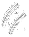
- FIG. 11 is a side perspective view of one seal body formed of a plurality of body segments
- FIG. 12 is an inner perspective view of one seal body segment
- FIG. 13 is an axial cross-sectional view of the seal assembly separate from the shaft and housing, showing relative radial displacement between the two seals in a first radial direction;
- FIG. 14 is an axial cross-sectional view of the seal assembly separate from the shaft and housing, showing relative radial displacement between the two seals in a second radial direction.
- FIGS. 1-14 a seal assembly 10 for sealing about a shaft 1 rotatable about a central axis A C and having an outer circumferential surface 2 .
- the seal assembly 10 has a centerline L C ( FIG. 1 ) substantially coaxial with the shaft axis A C and basically comprises first and second generally annular seals 12 , 14 , respectively, and at least one and preferably a plurality of biasing members 16 .
- the first and second seals 12 , 14 are disposable about the shaft 1 so as to be spaced apart axially along the shaft central axis A C , and are preferably disposed within an annular channel 3 of a housing 4 ( FIG. 1 ).
- Each biasing member 16 is configured to exert a generally axial biasing force on each one of the first and second seals 12 , 14 , so as to maintain axial spacing of the two seals 12 , 14 .
- each one of the two seals 12 , 14 has an inner circumferential surface 18 , 20 for sealing about the shaft outer surface 2 , which is provided by the shaft 1 itself or a sleeve, runner or other component mounted on the shaft 1 , and opposing inner and outer axial sides 22 A, 22 B and 24 A, 24 B, respectively.
- the seals 12 , 14 are arranged such that each seal inner axial side 22 A, 24 A faces the other seal inner axial side 24 A, 22 A, respectively.
- first seal 12 has at least one coupling pocket 26 extending generally axially inwardly from the first seal inner axial side 22 A and is configured to “loosely” couple the biasing member 16 with the seal 12 .
- the second seal 14 has at least one retaining pocket 28 extending generally axially inwardly from the second seal inner axial side 24 A, which is generally aligned with a proximal coupling pocket 26 .
- each biasing member 16 is installed within the seal assembly 10 such that a biasing member first end 16 a is disposed within the one coupling pocket 26 and an opposing, second end 16 b disposed within the retaining pocket 28 aligned with the particular coupling pocket 26 .
- each of one of the coupling pockets 26 and the retaining pockets 28 has a radial length l RC , l RR , respectively, i.e., a dimension along a radius through the seal assembly centerline L C .
- the pockets 26 , 28 are relatively sized so that the retaining pocket radial length l RR is substantially greater than the coupling pocket radial length l RC .
- the second end 16 b of each biasing member 16 is generally radially displaceable within the associated retaining pocket 28 when at least one of the first and second seals 12 , 14 radially displaces relative to the other one of the first and second seals 14 , 12 , as depicted in FIGS. 13 and 14 .
- the coupling and retaining pockets 26 , 28 each have a bottom end surface 30 , 32 , respectively, spaced axially from the seal body axial end 22 A, 24 A, respectively, and an inner enclosed sidewall surface 34 , 36 , respectively, extending between the respective axial end 22 A, 24 A and the respective bottom surface 30 , 32 .
- the sidewall surface 34 of the retaining pocket 26 is preferably sized slightly larger than an outer surface 19 ( FIG. 2 ) of the biasing member 16 , as discussed below, and the pockets 26 , 28 are arranged such that the bottom end surface 30 , 32 of each pocket 26 , 28 faces generally toward the bottom end surface 32 , 30 of the other pocket 28 , 26 .
- the biasing member 16 extends axially between the two bottom end surfaces 30 , 32 and exerts biasing force against each surface 30 , 32 , and thereby on the seals 12 , 14 .
- the retaining pocket end surface 32 is sized substantially larger than the coupling pocket end surface 30 , such that the biasing member second end 16 b is slidably displaceable against the retaining pocket end surface 32 while the first end 16 a remains generally stationary with respect to the first seal 12 , when one of the first and second seals 12 , 14 displaces relative to the other one of the two seals 14 , 12 .
- each biasing member 16 stays coupled with both seals 12 , 14 , as opposed to sliding off the seal end 24 A and becoming dislodged from the assembly 10 , and remains substantially undamaged (e.g., by being “pinched” under the inner circumferential surface 20 ), during relative displacement of the first and second seals 12 , 14 .
- Such relative seal displacement may occur during assembly/disassembly of the seals 12 , 14 or transient, extreme engine conditions leading to excessive vibration or shaft displacement, etc.
- each one of the coupling and retaining pockets 26 , 28 is preferably generally circular cylindrical, such that each inner sidewall surface 34 , 36 is a circular inner circumferential surface with an inner diameter ID C , ID R , respectively, providing the radial length l RC , l RR , as discussed above.
- the pockets 26 , 28 may alternatively be formed with inner sidewall surfaces 34 , 36 of any other desired shape, such as rectangular, hexagonal, etc.
- the retaining pocket inner diameter ID R is preferably at least two (2) times greater, and more preferably about two and a half (2.5) times greater, than the coupling pocket inner diameter ID C .
- the coupling pocket 26 and the retaining pocket 28 each have an axial length l AC , l AR , respectively, and the coupling pocket axial length l AC is substantially greater than the retaining pocket axial length l AR , which is preferably relatively shallow (e.g., 0.030′′).
- each biasing member 16 is disposed substantially “deeper” within the coupling pocket 26 as compared with its depth into the associated retaining pocket 28 .
- each biasing member 16 preferably has a generally circular cylindrical body 17 with an outer circumferential surface 19 and an outer diameter OD B sized “slightly” lesser than the coupling pocket inner diameter ID C ( FIG. 2 ).
- a generally minimal clearance space s C is defined between the biasing member 16 and the coupling pocket inner surface 34 , as indicated in FIG. 2 , so as to generally loosely retain the biasing member 16 within the coupling pocket 26 .
- the biasing member 16 is formed as or includes a coil compression spring, such that the cylindrical body 17 is comprised of a plurality of coils each having a diameter about equal to the body outer diameter OD B and an outer surface section collectively providing the body outer surface 19 .
- the biasing member 16 may alternatively be formed in any other appropriate manner, such as a solid rod of elastomeric material, a volute spring, etc., as long as the biasing member 16 is capable of functioning as generally described herein.
- each one of the first and second seals 12 , 14 is a circumferential shaft seal formed of a plurality of generally arcuate body segments 40 .
- Each arcuate body segment 40 has opposing circumferential ends 40 a , 40 b coupled to the end 40 b , 40 a of an adjacent segment 40 to form the annular seal 12 or 14 .
- each first end 40 a includes a projection 41 and each second end 40 b includes a cavity or recess 43 sized to receive the projection 41 from an adjacent body segment 40 .
- each body segment 40 also has opposing inner and outer circumferential surface sections 42 , 44 , respectively, and inner and outer axial ends 46 A, 46 B, respectively.
- each arcuate body segment 40 preferably further includes a slot 45 for receiving an anti-rotation pin (not shown).
- each arcuate body segment 40 has at least one lift pocket 48 extending generally outwardly from the inner surface section 42 and configured to receive fluid, preferably from an axial bleed slot 50 , such that the segment 40 is biased generally radially outwardly with respect to the central axis A C when the shaft 1 rotates within the seals 12 , 14 .
- each arcuate body segment 40 preferably has an elongated channel 52 extending inwardly from the outer surface and circumferentially between the two segment ends 40 a , 40 b , the channels 52 of the plurality of segments 40 collectively form a generally annular groove 54 .
- the seal assembly 10 preferably further comprises two generally annular biasing members 56 , 58 , each preferably a garter spring, each disposed with the annular groove 54 of a separate one of the first and second seals 12 , 14 .
- the annular biasing members 56 , 58 are configured to bias the plurality of arcuate body segments 40 generally radially inwardly to maintain the sealing surfaces 18 , 20 generally proximal to the shaft outer surface 2 .
- each first seal arcuate segment 40 preferably has at least one coupling pocket 26 and each second seal arcuate segment 40 preferably has at least one retaining pocket 28 .
- the seal assembly 10 comprises a plurality of the biasing members 16 each disposed in a separate one of the coupling pockets 26 and simultaneously within a separate, aligned one of the retaining pockets 28 .
- the additional pockets 26 , 28 are preferably located on the second seal 14 and the first seal 12 , respectively, such that each arcuate body segment 40 of each seal 12 , 14 is generally symmetrical with the facing body segment 40 of the other seal 14 , 12 .
- all the segments 40 of both the first and second seals 12 , 14 are preferably identically formed or fabricated and are interchangeable between the two seals 12 , 14 .
- the seal body segments 40 of the first seal 12 may be identical with each other, but different from the segments of the second seal 14 , and vice-versa.
- each of the first and second seals 12 , 14 may be of one-piece construction, i.e., not formed of multiple segments.
Landscapes
- Engineering & Computer Science (AREA)
- General Engineering & Computer Science (AREA)
- Mechanical Engineering (AREA)
- Mechanical Sealing (AREA)
- Sealing Devices (AREA)
Abstract
Description
Claims (13)
Priority Applications (4)
| Application Number | Priority Date | Filing Date | Title |
|---|---|---|---|
| US15/157,863 US10024435B2 (en) | 2016-05-18 | 2016-05-18 | Seal assembly with biasing member retaining pockets |
| GB1707015.2A GB2551886B (en) | 2016-05-18 | 2017-05-03 | Seal assembly with biasing member retaining pockets |
| CN201710320553.9A CN107420549B (en) | 2016-05-18 | 2017-05-09 | Seal assembly with biasing member retaining recess |
| FR1754100A FR3051527B1 (en) | 2016-05-18 | 2017-05-10 | ASSEMBLY FORMING A SEAL WITH SOLIDITY BODY RETAINING CAVITIES |
Applications Claiming Priority (1)
| Application Number | Priority Date | Filing Date | Title |
|---|---|---|---|
| US15/157,863 US10024435B2 (en) | 2016-05-18 | 2016-05-18 | Seal assembly with biasing member retaining pockets |
Publications (2)
| Publication Number | Publication Date |
|---|---|
| US20170335970A1 US20170335970A1 (en) | 2017-11-23 |
| US10024435B2 true US10024435B2 (en) | 2018-07-17 |
Family
ID=59010988
Family Applications (1)
| Application Number | Title | Priority Date | Filing Date |
|---|---|---|---|
| US15/157,863 Active US10024435B2 (en) | 2016-05-18 | 2016-05-18 | Seal assembly with biasing member retaining pockets |
Country Status (4)
| Country | Link |
|---|---|
| US (1) | US10024435B2 (en) |
| CN (1) | CN107420549B (en) |
| FR (1) | FR3051527B1 (en) |
| GB (1) | GB2551886B (en) |
Cited By (1)
| Publication number | Priority date | Publication date | Assignee | Title |
|---|---|---|---|---|
| US12421901B2 (en) | 2023-02-08 | 2025-09-23 | Rtx Corporation | Carbon radial seal |
Families Citing this family (4)
| Publication number | Priority date | Publication date | Assignee | Title |
|---|---|---|---|---|
| EP3667136B1 (en) * | 2017-08-07 | 2023-12-06 | Eagle Industry Co., Ltd. | Segment seal |
| US10995860B2 (en) * | 2018-05-31 | 2021-05-04 | Aktiebolaget Skf | Axial face seal assembly with outwardly-biased backing rings |
| GB2596555B (en) * | 2020-06-30 | 2023-10-11 | Crane John Uk Ltd | Apparatus and method |
| US11976730B2 (en) * | 2020-11-13 | 2024-05-07 | Mainspring Energy, Inc. | Manifold interface seal |
Citations (3)
| Publication number | Priority date | Publication date | Assignee | Title |
|---|---|---|---|---|
| US2867458A (en) * | 1956-02-23 | 1959-01-06 | Sealol Corp | Shaft seal for gas turbines and the like |
| US4943069A (en) * | 1988-05-10 | 1990-07-24 | Eagle Industry Co., Ltd. | Shaft seal disposed about a rotatable shaft |
| US7648143B2 (en) * | 2005-10-18 | 2010-01-19 | United Technologies Corporation | Tandem dual element intershaft carbon seal |
Family Cites Families (9)
| Publication number | Priority date | Publication date | Assignee | Title |
|---|---|---|---|---|
| US3472522A (en) * | 1966-08-26 | 1969-10-14 | Continental Oil Co | Sealing devices between rotating and nonrotating members |
| US4145058A (en) * | 1977-07-08 | 1979-03-20 | The United States Of America As Represented By The Administrator Of The National Aeronautics And Space Administration | Shaft seal assembly for high speed and high pressure applications |
| US4586719A (en) * | 1983-05-19 | 1986-05-06 | Borg-Warner Corporation | Mechanical seal |
| US5076589A (en) * | 1990-03-01 | 1991-12-31 | Bw/Ip International, Inc. | Mechanical seal |
| US5145189A (en) * | 1991-09-11 | 1992-09-08 | General Electric Company | Hydro-lift dynamic circumferential seal |
| US5516118A (en) * | 1993-07-19 | 1996-05-14 | Stein Seal Company | Circumferential hydrodynamic seals for sealing a bidirectionally rotatable member |
| ITMC20070238A1 (en) * | 2007-12-12 | 2009-06-13 | Meccanotecnica Umbra Spa | FRONT MECHANICAL SEAL FOR PUMPS, STRIPED RINGS WITH FLUID LUBRICATION, PERFECT TYPE. |
| WO2014172189A1 (en) * | 2013-04-15 | 2014-10-23 | Stein Seal Company | Circumferential back-to-back seal assembly with bifurcated flow |
| CN105443762A (en) * | 2015-12-14 | 2016-03-30 | 中国燃气涡轮研究院 | Double-ring circumferential sealing device |
-
2016
- 2016-05-18 US US15/157,863 patent/US10024435B2/en active Active
-
2017
- 2017-05-03 GB GB1707015.2A patent/GB2551886B/en active Active
- 2017-05-09 CN CN201710320553.9A patent/CN107420549B/en active Active
- 2017-05-10 FR FR1754100A patent/FR3051527B1/en active Active
Patent Citations (3)
| Publication number | Priority date | Publication date | Assignee | Title |
|---|---|---|---|---|
| US2867458A (en) * | 1956-02-23 | 1959-01-06 | Sealol Corp | Shaft seal for gas turbines and the like |
| US4943069A (en) * | 1988-05-10 | 1990-07-24 | Eagle Industry Co., Ltd. | Shaft seal disposed about a rotatable shaft |
| US7648143B2 (en) * | 2005-10-18 | 2010-01-19 | United Technologies Corporation | Tandem dual element intershaft carbon seal |
Cited By (1)
| Publication number | Priority date | Publication date | Assignee | Title |
|---|---|---|---|---|
| US12421901B2 (en) | 2023-02-08 | 2025-09-23 | Rtx Corporation | Carbon radial seal |
Also Published As
| Publication number | Publication date |
|---|---|
| FR3051527A1 (en) | 2017-11-24 |
| GB2551886A (en) | 2018-01-03 |
| US20170335970A1 (en) | 2017-11-23 |
| CN107420549B (en) | 2020-07-28 |
| GB201707015D0 (en) | 2017-06-14 |
| FR3051527B1 (en) | 2020-03-27 |
| CN107420549A (en) | 2017-12-01 |
| GB2551886B (en) | 2018-06-20 |
Similar Documents
| Publication | Publication Date | Title |
|---|---|---|
| US20170335970A1 (en) | Seal assembly with biasing member retaining pockets | |
| CN110273917B (en) | Seal kits for spherical plain bearings | |
| US4906109A (en) | Spring loaded guide ring | |
| US10371200B2 (en) | Combination elastomeric and cylindrical plain bearing | |
| US20090134583A1 (en) | Dual seal assembly | |
| CN110206888B (en) | Retainer device for an axial circumferential seal | |
| US20180163872A1 (en) | Outwardly Sealing Pumping Seal Assembly | |
| KR102382925B1 (en) | Annulr sealing assembly | |
| US11287043B2 (en) | High clearance seal assembly | |
| CN105697497B (en) | Anti-rotation clamp spring | |
| US20190144106A1 (en) | Combination elastomeric and ellipsoidal plain bearing | |
| WO2019041325A1 (en) | Piston sealing assembly for clutch disengagement system and clutch disengagement system | |
| WO2025192307A1 (en) | Rod packing | |
| CN109488692B (en) | Combined assembly comprising a bearing and a seal having a common outer body | |
| US10344868B2 (en) | Seal assembly with detachable spacer members | |
| US4244280A (en) | Piston for a pneumatic cylinder | |
| US8985589B1 (en) | Seal assembly with adjustable outside diameter | |
| US10443655B2 (en) | Combination bearing and seal assembly with common outer body | |
| ES2940210T3 (en) | Seal element for an axially sliding stem | |
| CN106050899B (en) | Plain bearings and/or systems incorporating plain bearings | |
| US20170307085A1 (en) | Circumferential shaft seal with radial displacement control | |
| AU2003267018B2 (en) | Element that defines a gap and is to be mounted on a shaft | |
| CA2773656A1 (en) | Floating wear sleeve assembly for shaft seals | |
| JP3159812U (en) | Piston ring, piston, engine | |
| RU183721U1 (en) | RADIAL BALL BEARING |
Legal Events
| Date | Code | Title | Description |
|---|---|---|---|
| AS | Assignment |
Owner name: KAYDON RING & SEAL, INC., MARYLAND Free format text: ASSIGNMENT OF ASSIGNORS INTEREST;ASSIGNOR:MANRY, JARED;REEL/FRAME:046044/0212 Effective date: 20160518 |
|
| AS | Assignment |
Owner name: KAYDON RING & SEAL, INC., MARYLAND Free format text: ASSIGNMENT OF ASSIGNORS INTEREST;ASSIGNOR:MANRY, JARED D.;REEL/FRAME:046050/0912 Effective date: 20160518 |
|
| STCF | Information on status: patent grant |
Free format text: PATENTED CASE |
|
| MAFP | Maintenance fee payment |
Free format text: PAYMENT OF MAINTENANCE FEE, 4TH YEAR, LARGE ENTITY (ORIGINAL EVENT CODE: M1551); ENTITY STATUS OF PATENT OWNER: LARGE ENTITY Year of fee payment: 4 |
|
| AS | Assignment |
Owner name: POLYMER CONCEPTS TECHNOLOGIES PBY, INC., CALIFORNIA Free format text: CORRECTIVE ASSIGNMENT TO CORRECT THE APPLICATION NUMBERS TO SERIAL NUMBERS PREVIOUSLY RECORDED AT REEL: 71502 FRAME: 556. ASSIGNOR(S) HEREBY CONFIRMS THE ASSIGNMENT;ASSIGNOR:KAYDON RING & SEAL, INC.;REEL/FRAME:074748/0042 Effective date: 20250411 |
|
| FEPP | Fee payment procedure |
Free format text: MAINTENANCE FEE REMINDER MAILED (ORIGINAL EVENT CODE: REM.); ENTITY STATUS OF PATENT OWNER: LARGE ENTITY |
|
| FEPP | Fee payment procedure |
Free format text: 7.5 YR SURCHARGE - LATE PMT W/IN 6 MO, LARGE ENTITY (ORIGINAL EVENT CODE: M1555); ENTITY STATUS OF PATENT OWNER: LARGE ENTITY |
|
| MAFP | Maintenance fee payment |
Free format text: PAYMENT OF MAINTENANCE FEE, 8TH YEAR, LARGE ENTITY (ORIGINAL EVENT CODE: M1552); ENTITY STATUS OF PATENT OWNER: LARGE ENTITY Year of fee payment: 8 |