US10023034B2 - Tonneau cover - Google Patents
Tonneau cover Download PDFInfo
- Publication number
- US10023034B2 US10023034B2 US15/429,594 US201715429594A US10023034B2 US 10023034 B2 US10023034 B2 US 10023034B2 US 201715429594 A US201715429594 A US 201715429594A US 10023034 B2 US10023034 B2 US 10023034B2
- Authority
- US
- United States
- Prior art keywords
- frame member
- edge
- margin
- flange
- catch
- Prior art date
- Legal status (The legal status is an assumption and is not a legal conclusion. Google has not performed a legal analysis and makes no representation as to the accuracy of the status listed.)
- Active
Links
Images


Classifications
-
- B—PERFORMING OPERATIONS; TRANSPORTING
- B60—VEHICLES IN GENERAL
- B60J—WINDOWS, WINDSCREENS, NON-FIXED ROOFS, DOORS, OR SIMILAR DEVICES FOR VEHICLES; REMOVABLE EXTERNAL PROTECTIVE COVERINGS SPECIALLY ADAPTED FOR VEHICLES
- B60J7/00—Non-fixed roofs; Roofs with movable panels, e.g. rotary sunroofs
- B60J7/08—Non-fixed roofs; Roofs with movable panels, e.g. rotary sunroofs of non-sliding type, i.e. movable or removable roofs or panels, e.g. let-down tops or roofs capable of being easily detached or of assuming a collapsed or inoperative position
- B60J7/12—Non-fixed roofs; Roofs with movable panels, e.g. rotary sunroofs of non-sliding type, i.e. movable or removable roofs or panels, e.g. let-down tops or roofs capable of being easily detached or of assuming a collapsed or inoperative position foldable; Tensioning mechanisms therefor, e.g. struts
- B60J7/14—Non-fixed roofs; Roofs with movable panels, e.g. rotary sunroofs of non-sliding type, i.e. movable or removable roofs or panels, e.g. let-down tops or roofs capable of being easily detached or of assuming a collapsed or inoperative position foldable; Tensioning mechanisms therefor, e.g. struts with a plurality of rigid plate-like elements or rigid non plate-like elements, e.g. with non-slidable, but pivotable or foldable movement
- B60J7/141—Non-fixed roofs; Roofs with movable panels, e.g. rotary sunroofs of non-sliding type, i.e. movable or removable roofs or panels, e.g. let-down tops or roofs capable of being easily detached or of assuming a collapsed or inoperative position foldable; Tensioning mechanisms therefor, e.g. struts with a plurality of rigid plate-like elements or rigid non plate-like elements, e.g. with non-slidable, but pivotable or foldable movement for covering load areas, e.g. for pick-up trucks
-
- B—PERFORMING OPERATIONS; TRANSPORTING
- B60—VEHICLES IN GENERAL
- B60J—WINDOWS, WINDSCREENS, NON-FIXED ROOFS, DOORS, OR SIMILAR DEVICES FOR VEHICLES; REMOVABLE EXTERNAL PROTECTIVE COVERINGS SPECIALLY ADAPTED FOR VEHICLES
- B60J7/00—Non-fixed roofs; Roofs with movable panels, e.g. rotary sunroofs
- B60J7/08—Non-fixed roofs; Roofs with movable panels, e.g. rotary sunroofs of non-sliding type, i.e. movable or removable roofs or panels, e.g. let-down tops or roofs capable of being easily detached or of assuming a collapsed or inoperative position
- B60J7/10—Non-fixed roofs; Roofs with movable panels, e.g. rotary sunroofs of non-sliding type, i.e. movable or removable roofs or panels, e.g. let-down tops or roofs capable of being easily detached or of assuming a collapsed or inoperative position readily detachable, e.g. tarpaulins with frames, or fastenings for tarpaulins
- B60J7/106—Non-fixed roofs; Roofs with movable panels, e.g. rotary sunroofs of non-sliding type, i.e. movable or removable roofs or panels, e.g. let-down tops or roofs capable of being easily detached or of assuming a collapsed or inoperative position readily detachable, e.g. tarpaulins with frames, or fastenings for tarpaulins readily detachable hard-tops
-
- B—PERFORMING OPERATIONS; TRANSPORTING
- B60—VEHICLES IN GENERAL
- B60P—VEHICLES ADAPTED FOR LOAD TRANSPORTATION OR TO TRANSPORT, TO CARRY, OR TO COMPRISE SPECIAL LOADS OR OBJECTS
- B60P7/00—Securing or covering of load on vehicles
- B60P7/02—Covering of load
Definitions
- the present disclosure relates to tonneau covers for vehicles and, more particularly, relates to a two-piece frame member connected to an edge of a rigid panel of a tonneau cover.
- Tonneau covers have been used for a number of years to cover the truck bed or cargo box of pickup trucks, to protect against dirt, debris, and other environmental contaminants, and to improve the aesthetic quality thereof.
- Such tonneau covers can be foldable when not being used to cover the bed of the pickup truck or for cargo protection or to otherwise allow access to the truck bed.
- Tonneau covers which include solid panels can be desirable, for example, to provide strength and rigidity and for their aesthetic quality.
- the present disclosure provides improvements in foldable tonneau covers incorporating rigid panels and in methods of assembling such tonneau covers.
- a method of assembling a tonneau cover can include providing a rigid panel having a first face, a second face opposite the first face, and an edge therebetween, with the second face having a second margin adjacent the edge, and the first face extending in a first plane and having a first margin adjacent the edge.
- a first frame member having a hook can be disposed along at least a portion of the edge of the rigid panel such that a first flange of the first frame member is overlying the first margin.
- a second frame member, distinct from the first frame member, having a catch can be disposed along at least a portion of the edge of the rigid panel such that a second flange of the second frame member is overlying the second margin.
- the first and second frame members can be moved toward each other in a coupling direction that is perpendicular to the first plane causing the hook of the first frame member and the catch of the second frame member to interlock with each other outboard of the edge of the rigid panel and coupling the first and second frame members together.
- causing the hook of the first frame member and the catch of the second frame member to interlock with each other can apply a compressive force to the rigid panel.
- a space can be provided adjacent the catch that is sufficient to permit movement of the hook in the coupling direction beyond a point at which the hook engages the catch to apply the compressive force.
- the hook and the catch can be provided with interlocking surfaces oriented to prevent disengagement from each other after interlocking the hook and the catch together.
- this can include providing the hook and the catch with interlocking surfaces oriented substantially perpendicular to the coupling direction.
- a tonneau cover for covering a truck bed can include a plurality of rigid panel sections configured to cover the at least a portion of the truck bed. At least one of the plurality of rigid panel sections can include a rigid panel, a first frame member, a second frame member and a coupling mechanism connecting the first frame member and the second frame member together.
- the rigid panel can have a first face extending in a first plane, a second face opposite the first face, and an edge therebetween.
- the first face of the rigid panel can having a first margin adjacent the edge.
- the second face of the rigid panel can have a second margin adjacent the edge.
- the first frame member can be disposed along at least a portion of the edge and can have a first flange overlying the first margin.
- the second frame member can be distinct from the first frame member and can be disposed along at least a portion of the edge and can have a second flange overlying the second margin.
- a coupling mechanism can connect the second frame member and the first frame member together outboard of the edge.
- the coupling mechanism can include a first coupling element extending in a direction perpendicular to the first plane and couplable with a second coupling element.
- the first and second coupling elements can be oriented to couple together through relative movement of the first and second frame members in the direction perpendicular to the first plane.
- FIG. 1 is a perspective view illustrating a foldable tonneau cover in accordance with the present disclosure in an unfolded configuration extending over a truck bed or cargo box of a pickup truck.
- FIG. 2 is a partial cross-section view of one example embodiment of a tonneau cover for a truck bed in accordance with the present disclosure.
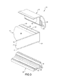
- FIG. 3 is a partial exploded view of the embodiment of FIG. 2 .
- FIGS. 4A, 4B and 4C are partial cross-sectional views illustrating the embodiment of FIG. 2 in various stages during an assembly process in accordance with the present disclosure.
- FIG. 5 is a partial cross-section view similar to FIG. 2 of another example embodiment of a tonneau cover for a truck bed in accordance with the present disclosure.
- FIG. 6 is a partial exploded view similar to FIG. 3 of the representative embodiment of FIG. 5 .
- FIGS. 1 through 6 illustrate various example embodiments of the present tonneau cover 10 having alternative structures.
- the embodiments will be described herein using common reference numerals to identify common elements, although the corresponding elements in the various embodiments may not be identical. It should be understood, however, that the present description should not be regarded as limiting the invention to any singular configuration and that alternative configurations, not illustrated, are further within the scope of the present teachings.
- a tonneau cover 10 for covering a truck bed or cargo box 11 is provided.
- the truck bed or cargo box 11 can be part of a pickup truck 13 as shown.
- the tonneau cover 10 can include a plurality of rigid panel sections 12 foldable between a deployed arrangement covering the truck bed 11 and a folded arrangement wherein the panel sections 12 are stacked, allowing access to the truck bed 11 .
- the tonneau cover 10 can include at least one rigid section 12 .
- This rigid section 12 can include a rigid panel 14 having a bottom face 16 adapted to or positioned to face the truck bed 11 when the tonneau cover 10 is in the deployed arrangement.
- the rigid panel 14 can have a top face 18 opposite the bottom face 16 , and an edge 20 between the top face 18 and the bottom face 16 .
- the top face 18 can include a top margin 22 adjacent the edge 20 .
- the bottom face 16 can include a bottom margin 24 adjacent the edge 20 .
- top face 18 and bottom face 16 can be provided by top and bottom outer sheet layers or skins, 19 and 17 , respectively, which can be made of metal or plastic material, that sandwich a central rigid foam core 21 .
- skins 17 , 19 can be made of aluminum or fiberglass reinforced polymer and the core 21 to which they can be laminated, can be made of a rigid polymeric or thermoplastic olefin.
- the tonneau cover 10 can further include a bottom frame member 26 disposed about the edge 20 and having a bottom flange 28 overlying the bottom margin 24 .
- the tonneau cover 10 can also include a top frame member 30 , distinct from the bottom frame member 26 , disposed about the edge 20 and having a top flange 32 overlying the top margin 22 .
- top and bottom it is equally appropriate to use alternative distinguishing language, such as “first” and “second” frame members, or “main” and “secondary” (or “lock strip”) frame members.
- the tonneau cover 10 includes a coupling mechanism 34 connecting the top frame member 30 and the bottom frame member 26 outboard the edge 20 .
- the coupling mechanism 34 can include a coupling element 40 on one of the frame members 30 and a cooperating coupling element 36 on the other of the frame members 26 that cooperate to couple the top frame member 30 and bottom frame member 26 together.
- the coupling elements 36 and 40 can interlock or inter-engage with each other.
- one of the top frame member 30 and bottom frame member 26 can comprise a coupling element in the form of a hook 36
- the other of the top frame member 30 and bottom frame member 26 can comprise a cooperating coupling element in the form of a catch feature 40 , which can be disposed within a receptacle 38 to insure and retain the interlocking arrangement or position.
- the coupling mechanism 34 can thus comprise hook 36 received in receptacle 38 to engage cooperating catch feature 40 .
- catch feature 40 can extend in a direction laterally away from edge 20 and hook 36 can include a flange extending laterally toward edge 20 and engaging the catch feature 40 .
- top frame member 30 and bottom frame member 26 can either or both be formed as a unified one-piece extruded strip.
- both of the top frame member 30 and bottom frame member 26 can be a unified extruded metal strip, such as a unified extruded aluminum strip.
- the bottom frame member 26 can be a unified extruded metal strip
- the top frame member 30 can be a unified extruded strip that is more flexible, such as a thinner or more flexible metal material or a plastic material, which can aid in sealing between the panel 14 and the top frame member 30 .
- the coupling mechanism such as the cooperating hook 36 and catch 40 coupling elements
- the coupling mechanism 34 can be integrally formed as a part of such respective extruded strips.
- the coupling mechanism 34 can include automatic or one-step cooperating coupling elements, such as the cooperating inter-engaging or interlocking hook 36 and catch 40 elements.
- the coupling mechanism 34 can couple the top frame member 30 and bottom frame member 26 together simply by appropriately positioning them with respect to each other, which can include positioning the hook 36 within a receptacle 38 housing the catch 40 .
- the coupling mechanism 34 can include one or more distinct or separate components beyond the top frame member 30 and the bottom frame member 26 .
- the coupling elements of the coupling mechanism 34 can include screws, pins, rivets, or clips, or other elements while cooperating coupling elements 40 can include threaded or non-threaded apertures, or other separate elements or integral features of one of the top frame member 30 or bottom frame member 26 .
- top flange 32 and bottom flange 28 apply a compressive force against opposing sides of the rigid panel 14 when the top frame member 30 and the bottom frame member 26 are coupled together by the coupling mechanism 34 to retain the rigid panel 14 therebetween.
- top frame member 30 and bottom frame member 26 and the coupling mechanism 34 can be positioned, can have a structure, or both, that can exert a compressive force against rigid panel 14 when the rigid panel 14 is retained between the top frame member 30 and bottom frame member 26 with these components assembled together in a collective, mated arrangement.
- tonneau cover 10 can comprise a material 42 disposed along an interface between any combination of top frame member 30 , bottom frame member 26 , and rigid panel 14 .
- the material 42 can be an adhesive, a sealant, or other suitable material.
- the material 42 can be applied as a strip, a bead, a liquid, a solid, or any other suitable means.
- the material 42 can be an adhesive and/or sealant applied in the form of a bead to one or both of the top flange 32 or top margin 22 to provide sealing and/or bonding between the top flange 32 and top margin 22 .
- the material 42 can alternatively or additionally be applied as a bead to one or both of the bottom flange 28 or bottom margin 24 to provide sealing and/or bonding between the bottom flange 28 and the bottom margin 24 .
- the material 42 can alternatively or additionally be applied in the form of a weather-strip or vibration isolation strip as described above with respect to the adhesive and/or sealant bead(s).
- sealing can be partially or completely provided by forming one of the top frame member 30 or bottom frame member 26 of a flexible or resilient material.
- top frame member 30 or panel lock strip of FIGS. 5 and 6 can comprise a unified extruded plastic flexible, resilient member. Such a structure can provide sealing and or vibration dampening instead of or in addition to the bead or strip material 42 described above.
- any of the panel 14 , top frame member 30 , bottom frame member 26 can be partially or fully covered by such a sheet material.
- such a sheet material can cover the top surfaces of the panel 14 and top frame member 30 and can extend into and terminate within a cover retention slot 41 .
- a method of assembling the tonneau cover 10 is further provided.
- the method can include providing a rigid panel 14 having a first or top face 18 , a second or bottom face 16 opposite the first face 18 , and an edge 20 therebetween.
- the first face 18 includes a first margin 22 adjacent the edge 20 and the second face 16 includes a second margin 24 adjacent the edge 20 .
- the method includes disposing a first frame member 30 along at least a portion of the edge 20 of the rigid panel 14 such that a first flange 32 of the first frame member 30 is overlying the first margin 22 .
- a plurality of first frame members 30 can, in some embodiments, be pre-assembled together to form a rectangular frame that is sized to correspond to the dimensions of the rigid panel 14 .
- Such a pre-assembled rectangular frame can be formed, for example, of four first frame members 30 having an identical cross-section.
- two first frame members 30 can be positioned on opposite sides of the rigid panel 14 and interconnected by intermediate frame members having a different configuration.
- an assembled rectangular frame comprising a plurality of the first frame members 30 , these second frame members 26 can be formed in place, by individually or separately serially positioning first frame members 30 adjacent a corresponding side or edge 20 of the panel 14 .
- a complete rectangular frame assembly need not be formed at all.
- a first frame member 30 coupled to a second frame member 26 can be provided along only one edge 20 of the rigid panel 14 .
- a first frame member 30 coupled to a second frame member 26 the first frame members 30 can be provided along only two opposite edges 20 of the rigid panel 14 parallel to each other, without any other frame members along the other set of parallel edges of the panel 14 to complete a rectangular frame.
- other embodiments may include any other possible arrangements.
- the first frame member 30 can, for example, be positioned such that first flange 32 faces generally upwardly.
- the adhesive and/or sealant material 42 can be readily applied upon the generally upwardly-facing first flange 32 .
- the first margin 22 of the rigid panel 14 can then be positioned directly over the first flange 32 and lowered into place against the adhesive and/or sealant material 42 , first flange 32 , or both, without the need for relative lateral movement between the first flange 32 and the first margin 22 or rigid panel 14 . Avoiding such relative lateral movement can facilitate better adhesion or sealing by the material 42 between the components.
- the material 42 can be applied to the second margin 24 of the rigid panel 14 , with the second margin 24 positioned facing generally upwardly.
- the method can further include disposing a second frame member 26 or locking strip, distinct from the first frame member 30 , along at least a portion of the edge 20 of the rigid panel 14 such that the second flange 28 of the second frame member 26 overlays the second margin 24 .
- the second flange 28 of the second frame member 26 can be positioned directly over the bottom or second margin 24 of the rigid panel 14 and lowered into place against the intervening material 42 , bottom or second flange 28 , or both, without the need for relative lateral movement between the second flange 28 or the material 42 , and the second margin 24 of the rigid panel 14 , which also can facilitate better adhesion or sealing by the material 42 between the components.
- these second frame members 26 can be pre-assembled into a rectangular frame assembly, or can be individually or separately serially positioned above and coupled to a corresponding first frame member 30 along the sides of the panel 14 .
- the coupling elements 36 and 40 of the coupling mechanism 34 can inter-engage or interlock to couple the first frame member 30 and the second frame member 26 together.
- the method can include coupling the first frame member 30 and the second frame member 26 together outboard the edge 20 of the rigid panel 14 .
- the coupling elements 36 and 40 can be positioned outboard of the edges 20 of the rigid panel 14 .
- first and second frame members 30 and 26 can be coupled together around opposing sides of the panel 14 .
- a first coupling extension of corner frame members 31 can next be inserted into ends of these opposing coupled frame members 30 , 26 .
- first and second frame members 30 and 26 can be positioned and coupled together along the remaining two sides of the panel 14 and around second coupling extensions of each corner frame member 31 .
- the adhesive and/or sealant material 42 can be applied between the first flange 32 of the first frame member 30 and the first margin 22 prior to the step of disposing the first frame member 30 along at least the portion of the edge 20 of the rigid panel 14 .
- the method can include applying an adhesive and/or sealant 42 between the second flange 28 of the second frame member 26 and the second margin 24 prior to the step of disposing the second frame member 26 along at least the portion of the edge 20 of the rigid panel 14 .
- such adhesive and/or bonding material may be provided at only one of these interfaces, or at neither interface.
- the method as described above with regard to the embodiment of FIGS. 2 through 4C identifies the first frame member as the top frame member 30 and the second frame member as the bottom frame member 26 . This need not be the case.
- the first frame member in the method description above can be bottom frame member 26 and the second frame member can be top frame member 30 .
- the method described above with regard to the embodiment of FIGS. 2 through 4C identifies the first flange and first margin as the top flange 32 and top margin 22 , respectively, and the second flange and second margin as the bottom flange 28 and bottom margin 24 , respectively.
- the first flange and first margin can be the bottom flange 28 and bottom margin 24 , respectively
- the second flange and second margin can be the top flange 32 and top margin 22 , respectively.
- Example embodiments are provided so that those who are skilled in the art can fully understand the tonneau covers for truck beds in accordance with this disclosure. These example embodiments provide numerous specific details such as examples of specific components, shapes, devices, and methods, to provide a thorough understanding of embodiments of the present disclosure. It will be apparent to those skilled in the art that specific details need not be employed, that example embodiments may be embodied in many different forms and that neither should be construed to limit the scope of the disclosure. Similarly, any aspect or combination of aspects illustrated or described in reference to one embodiment may be used in combination with one or more aspects illustrated or described in reference to any other embodiments. In some example embodiments, well-known processes, well-known device structures, and well-known technologies are not described in detail.
- Spatially relative terms such as “inner,” “outer,” “beneath,” “below,” “lower,” “above,” “upper,” and the like, may be used herein for ease of description to describe one element or feature's relationship to another element(s) or feature(s) as illustrated in the figures. Spatially relative terms may be intended to encompass different orientations of the device in use or operation in addition to the orientation depicted in the figures. For example, if the device in the figures is turned over, elements described as “below” or “beneath” other elements or features would then be oriented “above” the other elements or features. Thus, the example term “below” can encompass both an orientation of above and below. The device may be otherwise oriented (rotated 90 degrees or at other orientations) and the spatially relative descriptors used herein interpreted accordingly.
Abstract
Description
Claims (17)
Priority Applications (1)
| Application Number | Priority Date | Filing Date | Title |
|---|---|---|---|
| US15/429,594 US10023034B2 (en) | 2015-06-30 | 2017-02-10 | Tonneau cover |
Applications Claiming Priority (3)
| Application Number | Priority Date | Filing Date | Title |
|---|---|---|---|
| US201562186703P | 2015-06-30 | 2015-06-30 | |
| US14/831,227 US9623737B2 (en) | 2015-06-30 | 2015-08-20 | Tonneau cover |
| US15/429,594 US10023034B2 (en) | 2015-06-30 | 2017-02-10 | Tonneau cover |
Related Parent Applications (1)
| Application Number | Title | Priority Date | Filing Date |
|---|---|---|---|
| US14/831,227 Continuation US9623737B2 (en) | 2015-06-30 | 2015-08-20 | Tonneau cover |
Publications (2)
| Publication Number | Publication Date |
|---|---|
| US20170151864A1 US20170151864A1 (en) | 2017-06-01 |
| US10023034B2 true US10023034B2 (en) | 2018-07-17 |
Family
ID=57683496
Family Applications (2)
| Application Number | Title | Priority Date | Filing Date |
|---|---|---|---|
| US14/831,227 Active US9623737B2 (en) | 2015-06-30 | 2015-08-20 | Tonneau cover |
| US15/429,594 Active US10023034B2 (en) | 2015-06-30 | 2017-02-10 | Tonneau cover |
Family Applications Before (1)
| Application Number | Title | Priority Date | Filing Date |
|---|---|---|---|
| US14/831,227 Active US9623737B2 (en) | 2015-06-30 | 2015-08-20 | Tonneau cover |
Country Status (1)
| Country | Link |
|---|---|
| US (2) | US9623737B2 (en) |
Cited By (4)
| Publication number | Priority date | Publication date | Assignee | Title |
|---|---|---|---|---|
| US10322624B2 (en) * | 2017-09-29 | 2019-06-18 | Tectum Holdings, Inc. | Frame assembly |
| US11299021B2 (en) | 2019-07-17 | 2022-04-12 | Truck Accessories Group, Llc | Multi-panel tonneau cover |
| US11465477B2 (en) | 2018-05-02 | 2022-10-11 | Abc Technologies Inc. | Tonneau cover |
| US11479095B2 (en) | 2018-05-02 | 2022-10-25 | Abc Technologies Inc. | Tonneau cover |
Families Citing this family (9)
| Publication number | Priority date | Publication date | Assignee | Title |
|---|---|---|---|---|
| US9623737B2 (en) * | 2015-06-30 | 2017-04-18 | Extang Corporation | Tonneau cover |
| US10525803B2 (en) | 2017-04-26 | 2020-01-07 | Undercover, Inc. | Cover including a monolithic coating |
| US10245928B1 (en) | 2017-09-29 | 2019-04-02 | Tectum Holdings, Inc. | Tonneau cover with hidden hinges |
| US10315498B2 (en) | 2017-10-05 | 2019-06-11 | Tectum Holdings Inc. | Front and rear latches for tonneau system |
| USD918120S1 (en) * | 2018-04-19 | 2021-05-04 | Hang Shi | Watertight side-rail for tonneau cover |
| AU2019277208A1 (en) | 2018-05-31 | 2020-12-24 | Oakmoore Pty Ltd | A side rail |
| EP3802176A4 (en) * | 2018-05-31 | 2022-03-09 | Oakmoore Pty Ltd | A side rail |
| CN213831307U (en) * | 2020-11-13 | 2021-07-30 | 杭州金日汽车零部件有限公司 | Car cover waterproof rubber strip mounting structure |
| US11724582B2 (en) | 2020-12-03 | 2023-08-15 | Leer Group | Pinch latch assembly |
Citations (11)
| Publication number | Priority date | Publication date | Assignee | Title |
|---|---|---|---|---|
| US5636893A (en) | 1995-04-17 | 1997-06-10 | Wheatley; Donald E. | Folding hard panel tonneau cover with rail attachment |
| US5653491A (en) | 1995-09-15 | 1997-08-05 | Steffens Enterprises, Inc. | Folding cargo bay cover for pickup trucks |
| US6352296B1 (en) | 1998-04-28 | 2002-03-05 | Advance Cover Company | Folding cover for pickup truck bed |
| US20040245799A1 (en) | 2003-02-07 | 2004-12-09 | William Rusu | Hard tonneau cover |
| US20070035151A1 (en) | 2003-02-07 | 2007-02-15 | William Rusu | Hard tonneau cover |
| US20070210609A1 (en) | 2006-09-29 | 2007-09-13 | Israel Maimin | Pick-up truck box cover |
| US7484788B2 (en) | 2006-10-26 | 2009-02-03 | Extang Corporation | Solid fold tonneau system |
| US8262148B2 (en) | 2009-10-30 | 2012-09-11 | Extang Corporation | Tonneau cover system |
| US20130015678A1 (en) | 2011-07-12 | 2013-01-17 | Rugged Liner, Inc. | Rigid tonneau cover and clamp mechanism therefor |
| US20160176448A1 (en) | 2014-12-18 | 2016-06-23 | Laurmark Enterprises, Inc. | Tonneau panel locking feature |
| US9623737B2 (en) * | 2015-06-30 | 2017-04-18 | Extang Corporation | Tonneau cover |
-
2015
- 2015-08-20 US US14/831,227 patent/US9623737B2/en active Active
-
2017
- 2017-02-10 US US15/429,594 patent/US10023034B2/en active Active
Patent Citations (12)
| Publication number | Priority date | Publication date | Assignee | Title |
|---|---|---|---|---|
| US5636893A (en) | 1995-04-17 | 1997-06-10 | Wheatley; Donald E. | Folding hard panel tonneau cover with rail attachment |
| US5653491A (en) | 1995-09-15 | 1997-08-05 | Steffens Enterprises, Inc. | Folding cargo bay cover for pickup trucks |
| US6352296B1 (en) | 1998-04-28 | 2002-03-05 | Advance Cover Company | Folding cover for pickup truck bed |
| US20040245799A1 (en) | 2003-02-07 | 2004-12-09 | William Rusu | Hard tonneau cover |
| US20070035151A1 (en) | 2003-02-07 | 2007-02-15 | William Rusu | Hard tonneau cover |
| US7252322B2 (en) | 2003-02-07 | 2007-08-07 | William Rusu | Hard tonneau cover |
| US20070210609A1 (en) | 2006-09-29 | 2007-09-13 | Israel Maimin | Pick-up truck box cover |
| US7484788B2 (en) | 2006-10-26 | 2009-02-03 | Extang Corporation | Solid fold tonneau system |
| US8262148B2 (en) | 2009-10-30 | 2012-09-11 | Extang Corporation | Tonneau cover system |
| US20130015678A1 (en) | 2011-07-12 | 2013-01-17 | Rugged Liner, Inc. | Rigid tonneau cover and clamp mechanism therefor |
| US20160176448A1 (en) | 2014-12-18 | 2016-06-23 | Laurmark Enterprises, Inc. | Tonneau panel locking feature |
| US9623737B2 (en) * | 2015-06-30 | 2017-04-18 | Extang Corporation | Tonneau cover |
Cited By (4)
| Publication number | Priority date | Publication date | Assignee | Title |
|---|---|---|---|---|
| US10322624B2 (en) * | 2017-09-29 | 2019-06-18 | Tectum Holdings, Inc. | Frame assembly |
| US11465477B2 (en) | 2018-05-02 | 2022-10-11 | Abc Technologies Inc. | Tonneau cover |
| US11479095B2 (en) | 2018-05-02 | 2022-10-25 | Abc Technologies Inc. | Tonneau cover |
| US11299021B2 (en) | 2019-07-17 | 2022-04-12 | Truck Accessories Group, Llc | Multi-panel tonneau cover |
Also Published As
| Publication number | Publication date |
|---|---|
| US20170151864A1 (en) | 2017-06-01 |
| US20170001499A1 (en) | 2017-01-05 |
| US9623737B2 (en) | 2017-04-18 |
Similar Documents
| Publication | Publication Date | Title |
|---|---|---|
| US10023034B2 (en) | Tonneau cover | |
| US20160176448A1 (en) | Tonneau panel locking feature | |
| US9895963B1 (en) | Tonneau cover system with single piece spanning multiple panels | |
| US7484788B2 (en) | Solid fold tonneau system | |
| CA3007552C (en) | Frame assembly | |
| CA2971813C (en) | Foldable tonneau cover with an extruded forward section | |
| US8991134B2 (en) | Reconfigured modular building unit and method | |
| US9221238B2 (en) | Apparatus and method for associating the edge of a composite object with trim | |
| JP4938455B2 (en) | Laminate bonded structure with local reinforcement | |
| US20180354349A1 (en) | Door assembly with split carrier module | |
| US20170036589A1 (en) | Planar structure from a plurality of folding portions | |
| US20140183925A1 (en) | Vehicle seat trim closeout slide system | |
| CA2972514A1 (en) | Sidewall assembly for trailers | |
| US20140242897A1 (en) | One-way exhaust vent | |
| CA2930221C (en) | Tonneau cover | |
| US20190291550A1 (en) | Tonneau cover | |
| US20180118128A1 (en) | Lid assemblies for storage containers including vibration damping substrates | |
| US20080134509A1 (en) | Method of forming a logistics panel for use in a sidewall of a trailer | |
| CA2531536C (en) | Laminate with fill layer | |
| US6634449B2 (en) | Access hatch reinforcement module & method of installing an access hatch to an existing hood for a mobile vehicle | |
| US20150321443A1 (en) | Sandwich panel, container made of such a sandwich panel and method of manufacturing the same | |
| JP6997205B2 (en) | Car foldable interior lining panel | |
| US9790734B1 (en) | Interior reinforcing structure for a door and method of installing an interior reinforcing structure in a door | |
| TWI513606B (en) | Window construction of car sunroof | |
| US20210101646A1 (en) | Tonneau cover bed rail assembly with connector |
Legal Events
| Date | Code | Title | Description |
|---|---|---|---|
| AS | Assignment |
Owner name: EXTANG CORPORATION, MICHIGAN Free format text: ASSIGNMENT OF ASSIGNORS INTEREST;ASSIGNORS:FACCHINELLO, JEROME J.;FABROS, CHARLES A.;SIGNING DATES FROM 20150908 TO 20151015;REEL/FRAME:041224/0922 |
|
| STCF | Information on status: patent grant |
Free format text: PATENTED CASE |
|
| CC | Certificate of correction | ||
| AS | Assignment |
Owner name: WILMINGTON TRUST, NATIONAL ASSOCIATION, AS COLLATE Free format text: PATENT SECURITY AGREEMENT (INDENTURE);ASSIGNOR:EXTANG CORPORATION;REEL/FRAME:049673/0083 Effective date: 20190510 Owner name: JEFFERIES FINANCE LLC, ADMINISTRATIVE AGENT, NEW Y Free format text: FIRST LIEN PATENT SECURITY AGREEMENT SUPPLEMENT;ASSIGNOR:EXTANG CORPORATION;REEL/FRAME:049677/0810 Effective date: 20190607 Owner name: JEFFERIES FINANCE LLC, ADMINISTRATIVE AGENT, NEW Y Free format text: SECOND LIEN PATENT SECURITY AGREEMENT SUPPLEMENT;ASSIGNOR:EXTANG CORPORATION;REEL/FRAME:049677/0851 Effective date: 20190607 |
|
| AS | Assignment |
Owner name: BANK OF AMERICA, N.A., AS COLLATERAL AGENT, TEXAS Free format text: PATENT SECURITY AGREEMENT (ABL);ASSIGNOR:EXTANG CORPORATION;REEL/FRAME:055175/0678 Effective date: 20210129 Owner name: JEFFERIES FINANCE LLC, AS COLLATERAL AGENT, NEW YORK Free format text: PATENT SECURITY AGREEMENT (TL);ASSIGNOR:EXTANG CORPORATION;REEL/FRAME:055270/0428 Effective date: 20210129 |
|
| AS | Assignment |
Owner name: EXTANG CORPORATION, MICHIGAN Free format text: RELEASE OF SECOND LIEN SECURITY INTEREST IN PATENTS;ASSIGNOR:JEFFERIES FINANCE LLC, AS ADMINISTRATIVE AND COLLATERAL AGENT;REEL/FRAME:055189/0699 Effective date: 20210129 Owner name: EXTANG CORPORATION, MICHIGAN Free format text: RELEASE OF FIRST LIEN SECURITY INTEREST IN PATENTS;ASSIGNOR:JEFFERIES FINANCE LLC, AS ADMINISTRATIVE AND COLLATERAL AGENT;REEL/FRAME:055189/0690 Effective date: 20210129 |
|
| AS | Assignment |
Owner name: HUSKY LINERS, INC., KANSAS Free format text: RELEASE BY SECURED PARTY;ASSIGNOR:WILMINGTON TRUST, NATIONAL ASSOCIATION, AS COLLATERAL AGENT;REEL/FRAME:055193/0892 Effective date: 20210129 Owner name: OMIX-ADA, INC., GEORGIA Free format text: RELEASE BY SECURED PARTY;ASSIGNOR:WILMINGTON TRUST, NATIONAL ASSOCIATION, AS COLLATERAL AGENT;REEL/FRAME:055193/0892 Effective date: 20210129 Owner name: LUND MOTION PRODUCTS, INC., GEORGIA Free format text: RELEASE BY SECURED PARTY;ASSIGNOR:WILMINGTON TRUST, NATIONAL ASSOCIATION, AS COLLATERAL AGENT;REEL/FRAME:055193/0892 Effective date: 20210129 Owner name: RETRAX HOLDINGS, LLC, NORTH DAKOTA Free format text: RELEASE BY SECURED PARTY;ASSIGNOR:WILMINGTON TRUST, NATIONAL ASSOCIATION, AS COLLATERAL AGENT;REEL/FRAME:055193/0892 Effective date: 20210129 Owner name: UNDERCOVER, INC., MISSOURI Free format text: RELEASE BY SECURED PARTY;ASSIGNOR:WILMINGTON TRUST, NATIONAL ASSOCIATION, AS COLLATERAL AGENT;REEL/FRAME:055193/0892 Effective date: 20210129 Owner name: ADVANTAGE TRUCK ACCESSORIES INC., MICHIGAN Free format text: RELEASE BY SECURED PARTY;ASSIGNOR:WILMINGTON TRUST, NATIONAL ASSOCIATION, AS COLLATERAL AGENT;REEL/FRAME:055193/0892 Effective date: 20210129 Owner name: EXTANG CORPORATION, MICHIGAN Free format text: RELEASE BY SECURED PARTY;ASSIGNOR:WILMINGTON TRUST, NATIONAL ASSOCIATION, AS COLLATERAL AGENT;REEL/FRAME:055193/0892 Effective date: 20210129 Owner name: BUSHWACKER, INC., GEORGIA Free format text: RELEASE BY SECURED PARTY;ASSIGNOR:WILMINGTON TRUST, NATIONAL ASSOCIATION, AS COLLATERAL AGENT;REEL/FRAME:055193/0892 Effective date: 20210129 Owner name: BEDRUG, INC., TENNESSEE Free format text: RELEASE BY SECURED PARTY;ASSIGNOR:WILMINGTON TRUST, NATIONAL ASSOCIATION, AS COLLATERAL AGENT;REEL/FRAME:055193/0892 Effective date: 20210129 Owner name: LAURMARK ENTERPRISES, INC., MICHIGAN Free format text: RELEASE BY SECURED PARTY;ASSIGNOR:WILMINGTON TRUST, NATIONAL ASSOCIATION, AS COLLATERAL AGENT;REEL/FRAME:055193/0892 Effective date: 20210129 Owner name: RUGGED LINER, INC., MICHIGAN Free format text: RELEASE BY SECURED PARTY;ASSIGNOR:WILMINGTON TRUST, NATIONAL ASSOCIATION, AS COLLATERAL AGENT;REEL/FRAME:055193/0892 Effective date: 20210129 Owner name: TRUXEDO INC., SOUTH DAKOTA Free format text: RELEASE BY SECURED PARTY;ASSIGNOR:WILMINGTON TRUST, NATIONAL ASSOCIATION, AS COLLATERAL AGENT;REEL/FRAME:055193/0892 Effective date: 20210129 Owner name: ROLL-N-LOCK CORPORATION, GEORGIA Free format text: RELEASE BY SECURED PARTY;ASSIGNOR:WILMINGTON TRUST, NATIONAL ASSOCIATION, AS COLLATERAL AGENT;REEL/FRAME:055193/0892 Effective date: 20210129 Owner name: LUND, INC., GEORGIA Free format text: RELEASE BY SECURED PARTY;ASSIGNOR:WILMINGTON TRUST, NATIONAL ASSOCIATION, AS COLLATERAL AGENT;REEL/FRAME:055193/0892 Effective date: 20210129 Owner name: A.R.E. ACCESSORIES LLC, OHIO Free format text: RELEASE BY SECURED PARTY;ASSIGNOR:WILMINGTON TRUST, NATIONAL ASSOCIATION, AS COLLATERAL AGENT;REEL/FRAME:055193/0892 Effective date: 20210129 Owner name: N-FAB, INC., TEXAS Free format text: RELEASE BY SECURED PARTY;ASSIGNOR:WILMINGTON TRUST, NATIONAL ASSOCIATION, AS COLLATERAL AGENT;REEL/FRAME:055193/0892 Effective date: 20210129 |
|
| MAFP | Maintenance fee payment |
Free format text: PAYMENT OF MAINTENANCE FEE, 4TH YEAR, LARGE ENTITY (ORIGINAL EVENT CODE: M1551); ENTITY STATUS OF PATENT OWNER: LARGE ENTITY Year of fee payment: 4 |