US10022082B2 - Apparatus and method for detecting a state of a driver based on biometric signals of the driver - Google Patents
Apparatus and method for detecting a state of a driver based on biometric signals of the driver Download PDFInfo
- Publication number
- US10022082B2 US10022082B2 US15/356,083 US201615356083A US10022082B2 US 10022082 B2 US10022082 B2 US 10022082B2 US 201615356083 A US201615356083 A US 201615356083A US 10022082 B2 US10022082 B2 US 10022082B2
- Authority
- US
- United States
- Prior art keywords
- driver
- biometric signals
- electro
- biometric
- signals
- Prior art date
- Legal status (The legal status is an assumption and is not a legal conclusion. Google has not performed a legal analysis and makes no representation as to the accuracy of the status listed.)
- Active, expires
Links
Images


Classifications
-
- A—HUMAN NECESSITIES
- A61—MEDICAL OR VETERINARY SCIENCE; HYGIENE
- A61B—DIAGNOSIS; SURGERY; IDENTIFICATION
- A61B5/00—Measuring for diagnostic purposes; Identification of persons
- A61B5/72—Signal processing specially adapted for physiological signals or for diagnostic purposes
- A61B5/7235—Details of waveform analysis
- A61B5/7242—Details of waveform analysis using integration
-
- A—HUMAN NECESSITIES
- A61—MEDICAL OR VETERINARY SCIENCE; HYGIENE
- A61B—DIAGNOSIS; SURGERY; IDENTIFICATION
- A61B5/00—Measuring for diagnostic purposes; Identification of persons
- A61B5/16—Devices for psychotechnics; Testing reaction times ; Devices for evaluating the psychological state
- A61B5/18—Devices for psychotechnics; Testing reaction times ; Devices for evaluating the psychological state for vehicle drivers or machine operators
-
- A—HUMAN NECESSITIES
- A61—MEDICAL OR VETERINARY SCIENCE; HYGIENE
- A61B—DIAGNOSIS; SURGERY; IDENTIFICATION
- A61B5/00—Measuring for diagnostic purposes; Identification of persons
- A61B5/0059—Measuring for diagnostic purposes; Identification of persons using light, e.g. diagnosis by transillumination, diascopy, fluorescence
- A61B5/0075—Measuring for diagnostic purposes; Identification of persons using light, e.g. diagnosis by transillumination, diascopy, fluorescence by spectroscopy, i.e. measuring spectra, e.g. Raman spectroscopy, infrared absorption spectroscopy
-
- A—HUMAN NECESSITIES
- A61—MEDICAL OR VETERINARY SCIENCE; HYGIENE
- A61B—DIAGNOSIS; SURGERY; IDENTIFICATION
- A61B5/00—Measuring for diagnostic purposes; Identification of persons
- A61B5/02—Detecting, measuring or recording for evaluating the cardiovascular system, e.g. pulse, heart rate, blood pressure or blood flow
- A61B5/026—Measuring blood flow
- A61B5/0261—Measuring blood flow using optical means, e.g. infrared light
-
- A61B5/04012—
-
- A61B5/0402—
-
- A61B5/0476—
-
- A61B5/0478—
-
- A—HUMAN NECESSITIES
- A61—MEDICAL OR VETERINARY SCIENCE; HYGIENE
- A61B—DIAGNOSIS; SURGERY; IDENTIFICATION
- A61B5/00—Measuring for diagnostic purposes; Identification of persons
- A61B5/145—Measuring characteristics of blood in vivo, e.g. gas concentration or pH-value ; Measuring characteristics of body fluids or tissues, e.g. interstitial fluid or cerebral tissue
- A61B5/1455—Measuring characteristics of blood in vivo, e.g. gas concentration or pH-value ; Measuring characteristics of body fluids or tissues, e.g. interstitial fluid or cerebral tissue using optical sensors, e.g. spectral photometrical oximeters
-
- A—HUMAN NECESSITIES
- A61—MEDICAL OR VETERINARY SCIENCE; HYGIENE
- A61B—DIAGNOSIS; SURGERY; IDENTIFICATION
- A61B5/00—Measuring for diagnostic purposes; Identification of persons
- A61B5/24—Detecting, measuring or recording bioelectric or biomagnetic signals of the body or parts thereof
- A61B5/25—Bioelectric electrodes therefor
- A61B5/279—Bioelectric electrodes therefor specially adapted for particular uses
- A61B5/291—Bioelectric electrodes therefor specially adapted for particular uses for electroencephalography [EEG]
-
- A—HUMAN NECESSITIES
- A61—MEDICAL OR VETERINARY SCIENCE; HYGIENE
- A61B—DIAGNOSIS; SURGERY; IDENTIFICATION
- A61B5/00—Measuring for diagnostic purposes; Identification of persons
- A61B5/24—Detecting, measuring or recording bioelectric or biomagnetic signals of the body or parts thereof
- A61B5/316—Modalities, i.e. specific diagnostic methods
- A61B5/318—Heart-related electrical modalities, e.g. electrocardiography [ECG]
- A61B5/346—Analysis of electrocardiograms
- A61B5/349—Detecting specific parameters of the electrocardiograph cycle
- A61B5/352—Detecting R peaks, e.g. for synchronising diagnostic apparatus; Estimating R-R interval
-
- A—HUMAN NECESSITIES
- A61—MEDICAL OR VETERINARY SCIENCE; HYGIENE
- A61B—DIAGNOSIS; SURGERY; IDENTIFICATION
- A61B5/00—Measuring for diagnostic purposes; Identification of persons
- A61B5/24—Detecting, measuring or recording bioelectric or biomagnetic signals of the body or parts thereof
- A61B5/316—Modalities, i.e. specific diagnostic methods
- A61B5/369—Electroencephalography [EEG]
- A61B5/372—Analysis of electroencephalograms
-
- B—PERFORMING OPERATIONS; TRANSPORTING
- B60—VEHICLES IN GENERAL
- B60K—ARRANGEMENT OR MOUNTING OF PROPULSION UNITS OR OF TRANSMISSIONS IN VEHICLES; ARRANGEMENT OR MOUNTING OF PLURAL DIVERSE PRIME-MOVERS IN VEHICLES; AUXILIARY DRIVES FOR VEHICLES; INSTRUMENTATION OR DASHBOARDS FOR VEHICLES; ARRANGEMENTS IN CONNECTION WITH COOLING, AIR INTAKE, GAS EXHAUST OR FUEL SUPPLY OF PROPULSION UNITS IN VEHICLES
- B60K28/00—Safety devices for propulsion-unit control, specially adapted for, or arranged in, vehicles, e.g. preventing fuel supply or ignition in the event of potentially dangerous conditions
- B60K28/02—Safety devices for propulsion-unit control, specially adapted for, or arranged in, vehicles, e.g. preventing fuel supply or ignition in the event of potentially dangerous conditions responsive to conditions relating to the driver
-
- B—PERFORMING OPERATIONS; TRANSPORTING
- B60—VEHICLES IN GENERAL
- B60W—CONJOINT CONTROL OF VEHICLE SUB-UNITS OF DIFFERENT TYPE OR DIFFERENT FUNCTION; CONTROL SYSTEMS SPECIALLY ADAPTED FOR HYBRID VEHICLES; ROAD VEHICLE DRIVE CONTROL SYSTEMS FOR PURPOSES NOT RELATED TO THE CONTROL OF A PARTICULAR SUB-UNIT
- B60W40/00—Estimation or calculation of non-directly measurable driving parameters for road vehicle drive control systems not related to the control of a particular sub unit, e.g. by using mathematical models
- B60W40/08—Estimation or calculation of non-directly measurable driving parameters for road vehicle drive control systems not related to the control of a particular sub unit, e.g. by using mathematical models related to drivers or passengers
-
- A—HUMAN NECESSITIES
- A61—MEDICAL OR VETERINARY SCIENCE; HYGIENE
- A61B—DIAGNOSIS; SURGERY; IDENTIFICATION
- A61B5/00—Measuring for diagnostic purposes; Identification of persons
- A61B5/145—Measuring characteristics of blood in vivo, e.g. gas concentration or pH-value ; Measuring characteristics of body fluids or tissues, e.g. interstitial fluid or cerebral tissue
- A61B5/1455—Measuring characteristics of blood in vivo, e.g. gas concentration or pH-value ; Measuring characteristics of body fluids or tissues, e.g. interstitial fluid or cerebral tissue using optical sensors, e.g. spectral photometrical oximeters
- A61B5/14551—Measuring characteristics of blood in vivo, e.g. gas concentration or pH-value ; Measuring characteristics of body fluids or tissues, e.g. interstitial fluid or cerebral tissue using optical sensors, e.g. spectral photometrical oximeters for measuring blood gases
- A61B5/14553—Measuring characteristics of blood in vivo, e.g. gas concentration or pH-value ; Measuring characteristics of body fluids or tissues, e.g. interstitial fluid or cerebral tissue using optical sensors, e.g. spectral photometrical oximeters for measuring blood gases specially adapted for cerebral tissue
-
- B—PERFORMING OPERATIONS; TRANSPORTING
- B60—VEHICLES IN GENERAL
- B60W—CONJOINT CONTROL OF VEHICLE SUB-UNITS OF DIFFERENT TYPE OR DIFFERENT FUNCTION; CONTROL SYSTEMS SPECIALLY ADAPTED FOR HYBRID VEHICLES; ROAD VEHICLE DRIVE CONTROL SYSTEMS FOR PURPOSES NOT RELATED TO THE CONTROL OF A PARTICULAR SUB-UNIT
- B60W40/00—Estimation or calculation of non-directly measurable driving parameters for road vehicle drive control systems not related to the control of a particular sub unit, e.g. by using mathematical models
- B60W40/08—Estimation or calculation of non-directly measurable driving parameters for road vehicle drive control systems not related to the control of a particular sub unit, e.g. by using mathematical models related to drivers or passengers
- B60W2040/0872—Driver physiology
Definitions
- the present disclosure relates to an apparatus and a method for detecting a state of a driver based on biometric signals of the driver, and more particularly, to a technology of detecting biometric signals of a driver using a blood flow rate of brain, an electro-encephalography (EEG), and an electro-cardiography (ECG) of the driver.
- EEG electro-encephalography
- ECG electro-cardiography
- an image is analyzed by observing and sensing physical changes of the driver, that is, a motion of an eyelid, a gaze direction of an eye, a nod, and the like using a camera to sense when the driver is drowsy
- the sensed image has a predetermined value or more
- it is determined that the driver is in a state of drowsy driving and warns the drowsy driving of the drowsiness, thereby preventing the drowsy driving.
- Another method is determining whether or not the driver is in the state of drowsy driving by sensing and analyzing various biometric signals of the driver to determine a drowsy or sleeping state of the driver.
- EEG electro-encephalography
- ECG electro-oculography
- ECG electro-cardiography
- a physical state and a mental state of the driver described above may be detected by fine current signals flowing in both hands of the driver using an ECG sensor and a galvanic skin resistance (GSR) sensor, and may be more directly detected by fine current signals which may be detected from a skin around a head of the driver when a brain of the driver is active using an EEG sensor and an EGG sensor.
- GSR galvanic skin resistance
- a drowsy driving situation of the driver or a state in which an attention of the driver is distracted may be sensed by a change in the electro-encephalography and the electro-oculography of the driver.
- biometric signals of the driver are collected using a variety of sensors
- noise when noise is mixed in the collected biometric signals, there is a problem that it is difficult to accurately determine the state of the driver. Therefore, in order to accurately diagnose a drowsy state and an emotion state of the driver and provide feedback on these states to the driver, it is required to collect the biometric signals of the driver from which surrounding environment factors (e.g., noise, etc.) are removed.
- surrounding environment factors e.g., noise, etc.
- An aspect of the present disclosure provides an apparatus and a method for detecting biometric signals of a driver capable of classifying and analyzing the driver into a normal state and a fatigued state using a blood flow rate of a brain, an electro-encephalography (EEG), and an electro-cardiography (ECG) of the driver to thereby quantify a fatigue level of the driver using the analyzed biometric signals.
- EEG electro-encephalography
- ECG electro-cardiography
- an apparatus for detecting a state of a driver based on biometric signals of the driver includes: a biometric signal measuring part configured to measure the biometric signals including a blood flow rate of a brain of the driver using an electro-encephalography (EEG), an electro-cardiography (ECG), and a functional near-infrared spectroscopy (fNIRS) of the driver; a biometric signal integral part configured to integrate the measured biometric signals, to extract characteristics of the respective biometric signals from the measured biometric signals and to then integrate the extracted characteristics, or to classify the extracted characteristics of the biometric signals and to then integrate the classified characteristics; and a driver state detecting part configured to detect the state of the driver based on the integrated biometric signals.
- EEG electro-encephalography
- ECG electro-cardiography
- fNIRS functional near-infrared spectroscopy
- the biometric signal measuring part may include: an electro-encephalography measuring apparatus configured to measure the electro-encephalography occurring from the brain; an emitter configured to generate near-field infrared ray to measure the blood flow rate of the brain; and a detector configured to detect the near-field infrared ray reflected after the emitter generates the near-field infrared ray and to obtain electrical signals.
- characteristics of the electro-encephalography may be extracted by extracting characteristics of a relative power level (RPL) using electrodes attached to a scalp of the driver.
- RPL relative power level
- characteristics of the electro-cardiography may be extracted by extracting a component of R among components of P, Q, R, S, and T of the electro-cardiography and calculating a heart rate using the extracted component of R.
- the blood flow rate of the brain of the driver may be measured by measuring a reflection amount by a detector, converting light intensity into oxyhemoglobin and specific oxyhemoglobin concentrations using an absorption rate of light, and using the oxyhemoglobin and specific oxyhemoglobin concentrations.
- the driver state detecting part may calculate a driving condition level by applying the same weight to values of the electro-encephalography, the electro-cardiography, and the blood flow rate of the brain.
- a method for detecting a state of a driver based on biometric signals of the driver includes: measuring the biometric signals including a blood flow rate of a brain of the driver using an electro-encephalography (EEG), an electro-cardiography (ECG), and a functional near-infrared spectroscopy (fNIRS) of the driver; integrating the measured biometric signals, extracting characteristics of the respective biometric signals from the measured biometric signals and then integrating the extracted characteristics, or classifying the extracted characteristics of the biometric signals and then integrating the classified characteristics; and detecting the state of the driver based on the integrated biometric signals.
- EEG electro-encephalography
- ECG electro-cardiography
- fNIRS functional near-infrared spectroscopy
- characteristics of the electro-encephalography may be extracted by extracting characteristics of a relative power level (RPL) using electrodes attached to a scalp of the driver.
- RPL relative power level
- characteristics of the electro-cardiography may be extracted by extracting a component of R among components of P, Q, R, S, and T of the electro-cardiography and calculating a heart rate using the extracted component of R.
- the blood flow rate of the brain of the driver may be measured by measuring a reflection amount by a detector, converting light intensity into oxyhemoglobin and specific oxyhemoglobin concentrations using an absorption rate of light, and using the oxyhemoglobin and specific oxyhemoglobin concentrations.
- a driving condition level may be calculated by applying the same weight to values of the electro-encephalography, the electro-cardiography, and the blood flow rate of the brain.
- FIG. 1 is a configuration diagram, illustrating an apparatus for detecting a state of a driver based on biometric signals of the driver.
- FIG. 2 is a diagram illustrating a biometric signal measuring part within the apparatus for detecting a state of a driver.
- FIGS. 4A to 4C are diagrams illustrating a method for integrating multi-modality biometric signals of the biometric signal integral part within the apparatus for detecting a state of a driver.
- FIG. 5 is a diagram illustrating a method for extracting characteristics of an electroencephalography by the biometric signal integral part within the apparatus for detecting a state of a driver.
- FIG. 6 is a diagram illustrating a method for extracting characteristics of an electrocardiography by the biometric signal integral part within the apparatus for detecting a state of a driver.
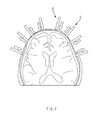
- FIG. 7 is a diagram illustrating a method for extracting characteristics of a functional near-infrared spectroscopy by the biometric signal integral part within the apparatus for detecting a state of a driver.
- FIG. 8 is a block diagram illustrating a computing system that executes the method for detecting a state of a driver based on biometric signals of the driver according to an exemplary embodiment of the present disclosure.
- an expression ‘and/or’ is used as a meaning including at least one of components listed before and after the expression.
- an expression ‘connected to/coupled to’ is used as a meaning including a case in which one component is directly connected to another component or is indirectly connected through another component.
- a singular form includes a plural form in the present specification.
- components, steps, operations, and elements mentioned by ‘comprise’ or ‘comprising’ used in the present specification mean the existence or addition of one or more other components, steps, operations, and elements.
- FIG. 1 is a configuration diagram illustrating an apparatus for detecting a state of a driver based on biometric signals of the driver.
- the biometric signal measuring part 100 measures the biometric signals including a blood flow rate of a brain of the driver using an electro-encephalography (EEG), an electro-cardiography (ECG), and a functional near-infrared spectroscopy (fNIRS) of the driver.
- EEG electro-encephalography
- ECG electro-cardiography
- fNIRS functional near-infrared spectroscopy
- the electro-encephalography which is a flow of electricity occurring when a signal is transferred between brain nerves in a nervous system of the driver, is an important indicator of measuring activity of a brain because it differently exhibits depending on a state of mind and body of the driver.
- the above-mentioned electro-encephalography may be measured by electrodes attached to a scalp of the driver, as a neurophysiological measuring method for electrical activity of the brain.
- the ECG which is an indicator analyzing electrical activity of a heart of a human for a defined time, plays an important role in determining a ratio and a constant period of heart beat, a size and a location of the heart, whether or not the heart is damaged, or the like.
- the ECG may be measured by electrodes attached to a skin of the driver and an external equipment connected to a body of the driver.
- the biometric signals measured using a biometric signal measuring apparatus configure data packets according to a data packet structure programmed in a main control unit (MCU) of hardware, and are transmitted to a personal computer (PC) at a rate of 250 Kbit per second through a Zigbee communication network.
- Software installed in the personal computer (PC) may receive the data packets of the biometric signals and output the biometric signals to a screen through a conversion algorithm, and the biometric signals may be stored in the main control unit (MCU) in a matrix structure in which channel and time forms are combined.
- the biometric signal integral part 110 integrates biometric signal data measured by the biometric signal measuring part 100 to utilize the integrated biometric signal data, simultaneously measures the respective biometric signals (the electro-encephalography (EEG), the electro-cardiography (ECG), the blood flow rate of brain, etc.) and then each extracts characteristics that best represent properties of the respective biometric signals, and integrates the extracted characteristics into one to generate data having high reliability.
- the respective biometric signals the electro-encephalography (EEG), the electro-cardiography (ECG), the blood flow rate of brain, etc.
- a final output value of the various kinds of classifiers may be integrated into one.
- the driver state detecting part 120 detects a state of the driver based on the integrated biometric signals.
- FIG. 2 is a diagram illustrating a biometric signal measuring part within the apparatus for detecting a state of a driver.
- the biometric signals measured using a biometric signal measuring apparatus configure data packets according to a data packet structure programmed in a main control unit (MCU) of hardware, and are transmitted to a personal computer (PC) at a rate of 250 Kbit per second through a Zigbee communication network.
- Software installed in the personal computer (PC) may receive the data packets of the biometric signals and output the biometric signals a screen through a conversion algorithm, and the biometric signals may be stored in the main control unit (MCU) in a matrix structure in which channel and time forms are combined.
- the biometric signal measuring part 100 includes an electro-encephalography measuring apparatus 200 , a detector 210 , and an emitter 220 in order to measure an electro-encephalography.
- the electro-encephalography measuring apparatus 200 measures (EEG measures) electrical signals occurring from the brain on the scalp.
- the above-mentioned detector 210 may be referred to as a near-field infrared detector or a photon detector.
- the emitter 220 is a near-field infrared generation apparatus for measuring the blood flow rate of the brain.
- the emitter 220 may include a light emitting diode (LED).
- FIG. 3 is a diagram illustrating a biometric signal integral part within the apparatus for detecting a state of a driver.
- the biometric signal integral part may measure the biometric signals using multi-modality A which measures various kinds of biometric signals at a time or simultaneously.
- the biometric signal integral part may integrate the biometric signals measured by the biometric signal measuring part, extract characteristics of the biometric signals from the biometric signals measured by the biometric signal measuring part and then integrate the extracted characteristics, or classify the extracted characteristics of the biometric signals and then integrate the classified characteristics.
- FIGS. 4A to 4C are diagrams illustrating a method for integrating multi-modality biometric signals of the biometric signal integral part within the apparatus for detecting a state of a driver according to an exemplary embodiment of the present disclosure.
- the biometric signal integral part may immediately integrate X the biometric signals (raw data) measured by the biometric signal measuring part.
- the biometric signal integral part may extract characteristics of the biometric signals from the biometric signals measured by the biometric signal measuring part and may then integrate Y the extracted characteristics of the biometric signals.
- the biometric signal integral part may classify the extracted characteristics of the biometric signals and may then integrate Z the classified biometric signals.
- FIG. 5 is a diagram illustrating a method for extracting characteristics of an electroencephalography by the biometric signal integral part within the apparatus for detecting a state of a driver according to an exemplary embodiment of the present disclosure.
- characteristics of the electroencephalography may be extracted by extracting relative power level (RPL) characteristics using electrodes attached to the scalp of the driver, converting time-series data into frequency data using Fourier transform, extracting an alpha wave (8 Hz to 13 Hz) and a beta wave (13 Hz to 30 Hz) after the conversion into the frequency data, and performing normalization by dividing the alpha wave and the beta wave with a power value of 1 Hz to 50 Hz.
- RPL relative power level
- FIG. 5 illustrates a comparison of the EEG between a normal driver group (a normal group) and a driver group (an abnormal group or a fatigued group) that becomes artificially fatigued, and as illustrated in FIG. 5 , an RPL value of the alpha wave is more significant in the driver group that becomes artificially fatigued than in the normal driver group.
- FIG. 5 is a diagram viewed from the top of a head of the driver, wherein the top of the head of the driver may be referred to as a frontal lobe, a bottom thereof may be referred to as an occipital lobe, and left and right sides may be referred to as a temporal lobe.
- the alpha wave significantly shows in the temporal lobe B of the abnormal group (is shown by strong or dark color), and the beta wave shows to be lower in the frontal lobe C of the abnormal group.
- FIG. 6 is a diagram illustrating a method for extracting characteristics of an electrocardiography by the biometric signal integral part within the apparatus for detecting a state of a driver.
- characteristics of the electrocardiography may be extracted by extracting a component of R among components of P, Q, R, S, and T of the electrocardiography and calculating a heart rate using the extracted component of R.
- the heart rate may be calculated by measuring the electrocardiography of the driver, calculating the component of R for 1 minute, and using the calculated component of R.
- FIG. 7 is a diagram illustrating method for extracting characteristics of functional Near-Infrared spectroscopy by the biometric signal integral part within the apparatus for detecting a state of a driver.
- oxyhemoglobin concentration (HbO) and specific oxyhemoglobin concentration (HbR) may be detected by measuring a reflection amount by the detector, converting light intensity into the oxyhemoglobin concentration and the specific oxyhemoglobin concentration using an absorption rate of light such as modified Beer-Lambert Law (mBLL), and using oxyhemoglobin and specific oxyhemoglobin as characteristics, and the blood flow rate of the brain of the driver may be measured using the oxyhemoglobin concentration and the specific oxyhemoglobin concentration.
- mBLL modified Beer-Lambert Law
- the emitter D generates near-field infrared ray
- the detector E measures the near-field infrared ray which is reflected or scattered.
- a value of the measured near-field infrared ray is the light intensity, and the oxyhemoglobin concentration and the specific oxyhemoglobin concentration (HbO/HbR) of the brain may be measured using Modified Beer-Lambert Law (mBLL).
- mBLL Modified Beer-Lambert Law
- the driver state detecting part within the apparatus for detecting a state of a driver will describe a method for extracting a driving condition level of the driver.
- values of the electro-encephalography (the alpha wave, the beta wave), the electro-cardiography (the heart rate), the blood flow rate of the brain (the oxyhemoglobin concentration) are calculated using the following Equation 1.
- norm(x) is an equation that maps three signals having magnitudes of different ranges to a value from 0 to 1, and x means characteristics extracted from the respective signals, which means the alpha wave and the beta wave in the electro-encephalography, means the heart rate in the electro-cardiography, and means the oxyhemoglobin concentration (HbO) in the blood flow rate of the brain.
- the driving condition level (DCL) is calculated by applying the same weight to the values of the electro-encephalography (the alpha wave, the beta wave), the electro-cardiography (the heart rate), the blood flow rate of the brain (the oxyhemoglobin concentration), which is as in the following Equation 2.
- DCL norm ⁇ ( Beta ⁇ ⁇ Wave Alpha ⁇ ⁇ Wave ) + norm ⁇ ( Oxyhemoglobin ⁇ ⁇ Concentration ) + norm ⁇ ( Heart ⁇ ⁇ Rate ) ⁇ ⁇ ( 0 ⁇ norm ⁇ ( Beta ⁇ ⁇ Wave Alpha ⁇ ⁇ Wave ) ⁇ 1.0 ⁇ norm ( Oxyhemoglobin ⁇ ⁇ Concentration ) ⁇ 1 , 0 ⁇ norm ⁇ ( Heart ⁇ ⁇ Rate ) ⁇ 1.0 ⁇ DCL ⁇ 3 ) [ Equation ⁇ ⁇ 2 ]
- FIG. 8 is a block diagram illustrating a computing system that executes the method for detecting a state of a driver based on biometric signals of the driver according to an exemplary embodiment of the present disclosure.
- a computing system 1000 may include at least one processor 1100 , a memory 1300 , a user interface input device 1400 , a user interface output device 1500 , a storage 1600 , and a network interface 1700 which are connected through a bus 1200 .
- the processor 1100 may be a central processing unit (CPU) or a semiconductor device executing processes for instructions which are stored in the memory 1300 and/or the storage 1600 .
- the memory 1300 and the storage 1600 may include various kinds of volatile or non-volatile storing media.
- the memory 1300 may include a read only memory (ROM) and a random access memory (RAM).
- the software module may be resided on a storing medium (i.e., the memory 1300 and/or the storage 1600 ) such as a random access memory (RAM) memory, a flash memory, a read only memory (ROM) memory, an erasable programmable read only memory (EPROM) memory, an electrically erasable programmable read only memory (EEPROM) memory, a register, a hard disk, a removable disk, or a compact disc-read only memory (CD-ROM).
- RAM random access memory
- ROM read only memory
- EPROM erasable programmable read only memory
- EEPROM electrically erasable programmable read only memory
- An illustrative storing medium may be coupled to the processor 1100 and the processor 1100 may read information from the storing medium and write the information into the storing medium.
- the storing medium may also be integral with the processor 1100 .
- the processor and the storing medium may also be resided within an application specific integrated circuit (ASIC).
- ASIC application specific integrated circuit
- the ASIC may also be resided within a user terminal.
- the processor and the storing medium may also be resided within the user terminal as an individual component.
- the apparatus and the method for detecting biometric signals of a driver may classify and analyze the driver into the normal state and the fatigued state using the blood flow rate of brain, the electro-encephalography (EEG), and the electro-cardiography (ECG) of the driver to thereby quantify the fatigue level of the driver using the analyzed biometric signals.
- EEG electro-encephalography
- ECG electro-cardiography
Landscapes
- Health & Medical Sciences (AREA)
- Life Sciences & Earth Sciences (AREA)
- Engineering & Computer Science (AREA)
- Physics & Mathematics (AREA)
- Heart & Thoracic Surgery (AREA)
- Medical Informatics (AREA)
- Biophysics (AREA)
- Pathology (AREA)
- Veterinary Medicine (AREA)
- Biomedical Technology (AREA)
- Public Health (AREA)
- Animal Behavior & Ethology (AREA)
- General Health & Medical Sciences (AREA)
- Surgery (AREA)
- Molecular Biology (AREA)
- Cardiology (AREA)
- Psychiatry (AREA)
- Psychology (AREA)
- Physiology (AREA)
- Child & Adolescent Psychology (AREA)
- Educational Technology (AREA)
- Hospice & Palliative Care (AREA)
- Developmental Disabilities (AREA)
- Hematology (AREA)
- Social Psychology (AREA)
- Spectroscopy & Molecular Physics (AREA)
- Mechanical Engineering (AREA)
- Transportation (AREA)
- Automation & Control Theory (AREA)
- Mathematical Physics (AREA)
- Signal Processing (AREA)
- Computer Vision & Pattern Recognition (AREA)
- Chemical & Material Sciences (AREA)
- Combustion & Propulsion (AREA)
- Artificial Intelligence (AREA)
- Optics & Photonics (AREA)
- Measuring Pulse, Heart Rate, Blood Pressure Or Blood Flow (AREA)
- Measurement Of The Respiration, Hearing Ability, Form, And Blood Characteristics Of Living Organisms (AREA)
- Measurement And Recording Of Electrical Phenomena And Electrical Characteristics Of The Living Body (AREA)
Abstract
Description
Claims (11)
Applications Claiming Priority (2)
| Application Number | Priority Date | Filing Date | Title |
|---|---|---|---|
| KR1020160080410A KR20180001367A (en) | 2016-06-27 | 2016-06-27 | Apparatus and Method for detecting state of driver based on biometric signals of driver |
| KR10-2016-0080410 | 2016-06-27 |
Publications (2)
| Publication Number | Publication Date |
|---|---|
| US20170367635A1 US20170367635A1 (en) | 2017-12-28 |
| US10022082B2 true US10022082B2 (en) | 2018-07-17 |
Family
ID=60579777
Family Applications (1)
| Application Number | Title | Priority Date | Filing Date |
|---|---|---|---|
| US15/356,083 Active 2037-02-10 US10022082B2 (en) | 2016-06-27 | 2016-11-18 | Apparatus and method for detecting a state of a driver based on biometric signals of the driver |
Country Status (4)
| Country | Link |
|---|---|
| US (1) | US10022082B2 (en) |
| KR (1) | KR20180001367A (en) |
| CN (1) | CN107536617A (en) |
| DE (1) | DE102016123159A1 (en) |
Families Citing this family (23)
| Publication number | Priority date | Publication date | Assignee | Title |
|---|---|---|---|---|
| US10922567B2 (en) | 2010-06-07 | 2021-02-16 | Affectiva, Inc. | Cognitive state based vehicle manipulation using near-infrared image processing |
| US10379535B2 (en) | 2017-10-24 | 2019-08-13 | Lear Corporation | Drowsiness sensing system |
| US10836403B2 (en) | 2017-12-04 | 2020-11-17 | Lear Corporation | Distractedness sensing system |
| US10210409B1 (en) * | 2018-02-07 | 2019-02-19 | Lear Corporation | Seating system with occupant stimulation and sensing |
| WO2019185303A1 (en) * | 2018-03-28 | 2019-10-03 | Robert Bosch Gmbh | In-vehicle system for estimating a scene inside a vehicle cabin |
| US10867218B2 (en) | 2018-04-26 | 2020-12-15 | Lear Corporation | Biometric sensor fusion to classify vehicle passenger state |
| CN108742614B (en) * | 2018-06-11 | 2021-03-30 | 上海交通大学 | A method for detecting muscle fatigue by combining surface electromyography and near-infrared spectroscopy |
| CN109044379A (en) * | 2018-06-26 | 2018-12-21 | 深圳市元征科技股份有限公司 | A kind of fatigue driving judgment method, system, equipment and computer storage medium |
| CN109710065B (en) * | 2018-12-18 | 2021-12-28 | 苏州大学 | Method for recognizing walking regulation intention based on brain hemoglobin information |
| CN109620205B (en) * | 2018-12-26 | 2022-10-28 | 上海联影智能医疗科技有限公司 | Electrocardiogram data classification method and device, computer equipment and storage medium |
| US12059980B2 (en) | 2019-06-21 | 2024-08-13 | Lear Corporation | Seat system and method of control |
| KR20210009595A (en) * | 2019-07-17 | 2021-01-27 | 주식회사 이엠텍 | Electroencephalogram having nir irradiation part |
| US11524691B2 (en) | 2019-07-29 | 2022-12-13 | Lear Corporation | System and method for controlling an interior environmental condition in a vehicle |
| CN110507319B (en) * | 2019-09-04 | 2022-04-15 | 杭州回车电子科技有限公司 | Fatigue degree detection method and equipment |
| CN110742602B (en) * | 2019-10-15 | 2021-02-19 | 武汉理工大学 | An aggressive driving state recognition method based on EEG and vehicle driving data |
| US11813060B2 (en) * | 2020-06-29 | 2023-11-14 | Lear Corporation | System and method for biometric evoked response monitoring and feedback |
| KR20220013202A (en) * | 2020-07-24 | 2022-02-04 | 현대자동차주식회사 | Apparatus for detecting stress level of a driver and method thereof |
| KR20220055209A (en) * | 2020-10-26 | 2022-05-03 | 현대자동차주식회사 | Vehicle and method for controlling thereof |
| CN112190235B (en) * | 2020-12-08 | 2021-03-16 | 四川大学 | A fNIRS data processing method based on deceptive behavior in different situations |
| CN113261974A (en) * | 2021-06-07 | 2021-08-17 | 吉林大学 | Sports fatigue monitoring method based on multiple physiological signals |
| CN116350190B (en) * | 2023-05-29 | 2023-08-18 | 中国第一汽车股份有限公司 | Driving capability determining method, electronic equipment and storage medium |
| KR102756465B1 (en) * | 2023-11-01 | 2025-01-21 | 주식회사 현대이디에스 | Sleep scoring method to assess sleep quality |
| KR102731082B1 (en) * | 2023-12-20 | 2024-11-15 | 주식회사 엔서 | Measuring Apparatus for Measuring Biometric Information, Including Blood Pressure, Non-invasively |
Citations (16)
| Publication number | Priority date | Publication date | Assignee | Title |
|---|---|---|---|---|
| JP2004110546A (en) | 2002-09-19 | 2004-04-08 | Denso Corp | Display device, audio device, and actuator control device |
| JP2006280512A (en) | 2005-03-31 | 2006-10-19 | National Institute Of Information & Communication Technology | Method and apparatus for presenting danger signal to vehicle operator |
| US20070010754A1 (en) | 2003-03-20 | 2007-01-11 | Klaus-Robert Muller | Method for initiating occupant-assisted measures inside a vehicle |
| US20100109881A1 (en) * | 2008-11-05 | 2010-05-06 | Azim Eskandarian | Unobtrusive driver drowsiness detection system and method |
| US20120101690A1 (en) * | 2010-03-12 | 2012-04-26 | Tata Consultancy Services Limited | System for vehicle security, personalization and cardiac activity monitoring of a driver |
| KR20120068625A (en) | 2010-12-17 | 2012-06-27 | 대구대학교 산학협력단 | Acceleration and decelerati on system of driving simulator system for disabled using eeg sensor and cont rol method of thereof |
| KR20140022312A (en) | 2012-08-14 | 2014-02-24 | 엘지전자 주식회사 | Device for measuring vital signs of drivers |
| US8725311B1 (en) * | 2011-03-14 | 2014-05-13 | American Vehicular Sciences, LLC | Driver health and fatigue monitoring system and method |
| KR20140096609A (en) | 2013-01-28 | 2014-08-06 | 주식회사 라이프사이언스테크놀로지 | Method for Service of Driver Identfy and Bio Signal Information of Driver |
| JP2014167438A (en) | 2013-02-28 | 2014-09-11 | Denso Corp | Information notification device |
| KR20140127977A (en) | 2013-04-26 | 2014-11-05 | 주식회사 라이프사이언스테크놀로지 | Apparatus for Judgment of Drowsy Driving using Bio Signal |
| KR20150012104A (en) | 2013-07-24 | 2015-02-03 | 현대자동차주식회사 | Apparatus and method for determining drowsy state |
| KR20150078476A (en) | 2013-12-30 | 2015-07-08 | 광운대학교 산학협력단 | Bio-signal monitoring system for drivers in vehicle, method, system and apparatus for monitoring bio-signal |
| US20150265201A1 (en) * | 2014-03-18 | 2015-09-24 | J. Kimo Arbas | System and method to detect alertness of machine operator |
| KR20160018134A (en) | 2014-08-08 | 2016-02-17 | 최상식 | Head wearable type apparatus and method for managing state of user |
| US9873437B2 (en) * | 2011-02-18 | 2018-01-23 | Honda Motor Co., Ltd. | Coordinated vehicle response system and method for driver behavior |
Family Cites Families (7)
| Publication number | Priority date | Publication date | Assignee | Title |
|---|---|---|---|---|
| CN101375796B (en) * | 2008-09-18 | 2010-06-02 | 浙江工业大学 | Fatigue driving real-time detection system |
| EP2237237B1 (en) * | 2009-03-30 | 2013-03-20 | Tobii Technology AB | Eye closure detection using structured illumination |
| CN102715902A (en) * | 2012-06-15 | 2012-10-10 | 天津大学 | Emotion monitoring method for special people |
| CN104665849B (en) * | 2014-12-11 | 2017-03-01 | 西南交通大学 | A kind of high ferro dispatcher based on the interaction of many physiological signals multi-model stress detection method |
| KR20160080410A (en) | 2014-12-29 | 2016-07-08 | 주식회사 레이언스 | Thin film thickness measurement sensor module and thin film deposition apparatus including the same |
| CN105559760B (en) * | 2015-12-10 | 2018-10-19 | 塔普翊海(上海)智能科技有限公司 | The personal mode identification method of helmet |
| CN105438174B (en) * | 2016-01-02 | 2016-11-16 | 刘更新 | Taximan's state automatic early-warning platform |
-
2016
- 2016-06-27 KR KR1020160080410A patent/KR20180001367A/en not_active Ceased
- 2016-11-18 US US15/356,083 patent/US10022082B2/en active Active
- 2016-11-30 DE DE102016123159.2A patent/DE102016123159A1/en active Pending
- 2016-11-30 CN CN201611081026.9A patent/CN107536617A/en not_active Withdrawn
Patent Citations (16)
| Publication number | Priority date | Publication date | Assignee | Title |
|---|---|---|---|---|
| JP2004110546A (en) | 2002-09-19 | 2004-04-08 | Denso Corp | Display device, audio device, and actuator control device |
| US20070010754A1 (en) | 2003-03-20 | 2007-01-11 | Klaus-Robert Muller | Method for initiating occupant-assisted measures inside a vehicle |
| JP2006280512A (en) | 2005-03-31 | 2006-10-19 | National Institute Of Information & Communication Technology | Method and apparatus for presenting danger signal to vehicle operator |
| US20100109881A1 (en) * | 2008-11-05 | 2010-05-06 | Azim Eskandarian | Unobtrusive driver drowsiness detection system and method |
| US20120101690A1 (en) * | 2010-03-12 | 2012-04-26 | Tata Consultancy Services Limited | System for vehicle security, personalization and cardiac activity monitoring of a driver |
| KR20120068625A (en) | 2010-12-17 | 2012-06-27 | 대구대학교 산학협력단 | Acceleration and decelerati on system of driving simulator system for disabled using eeg sensor and cont rol method of thereof |
| US9873437B2 (en) * | 2011-02-18 | 2018-01-23 | Honda Motor Co., Ltd. | Coordinated vehicle response system and method for driver behavior |
| US8725311B1 (en) * | 2011-03-14 | 2014-05-13 | American Vehicular Sciences, LLC | Driver health and fatigue monitoring system and method |
| KR20140022312A (en) | 2012-08-14 | 2014-02-24 | 엘지전자 주식회사 | Device for measuring vital signs of drivers |
| KR20140096609A (en) | 2013-01-28 | 2014-08-06 | 주식회사 라이프사이언스테크놀로지 | Method for Service of Driver Identfy and Bio Signal Information of Driver |
| JP2014167438A (en) | 2013-02-28 | 2014-09-11 | Denso Corp | Information notification device |
| KR20140127977A (en) | 2013-04-26 | 2014-11-05 | 주식회사 라이프사이언스테크놀로지 | Apparatus for Judgment of Drowsy Driving using Bio Signal |
| KR20150012104A (en) | 2013-07-24 | 2015-02-03 | 현대자동차주식회사 | Apparatus and method for determining drowsy state |
| KR20150078476A (en) | 2013-12-30 | 2015-07-08 | 광운대학교 산학협력단 | Bio-signal monitoring system for drivers in vehicle, method, system and apparatus for monitoring bio-signal |
| US20150265201A1 (en) * | 2014-03-18 | 2015-09-24 | J. Kimo Arbas | System and method to detect alertness of machine operator |
| KR20160018134A (en) | 2014-08-08 | 2016-02-17 | 최상식 | Head wearable type apparatus and method for managing state of user |
Also Published As
| Publication number | Publication date |
|---|---|
| DE102016123159A1 (en) | 2017-12-28 |
| CN107536617A (en) | 2018-01-05 |
| KR20180001367A (en) | 2018-01-04 |
| US20170367635A1 (en) | 2017-12-28 |
Similar Documents
| Publication | Publication Date | Title |
|---|---|---|
| US10022082B2 (en) | Apparatus and method for detecting a state of a driver based on biometric signals of the driver | |
| Zhang et al. | A systematic survey of driving fatigue monitoring | |
| Murugan et al. | Detection and analysis: Driver state with electrocardiogram (ECG) | |
| US11172835B2 (en) | Method and system for monitoring sleep | |
| Mohanavelu et al. | Machine learning-based approach for identifying mental workload of pilots | |
| Kartsch et al. | A sensor fusion approach for drowsiness detection in wearable ultra-low-power systems | |
| Chen et al. | Automatic detection of alertness/drowsiness from physiological signals using wavelet-based nonlinear features and machine learning | |
| Pratama et al. | A review on driver drowsiness based on image, bio-signal, and driver behavior | |
| Patel et al. | Applying neural network analysis on heart rate variability data to assess driver fatigue | |
| Zhao et al. | Real-time assessment of the cross-task mental workload using physiological measures during anomaly detection | |
| US20210022670A1 (en) | Systems and methods for diagnosing sleep | |
| Vandana et al. | A review of EEG signal analysis for diagnosis of neurological disorders using machine learning | |
| CN102149320A (en) | Method and system for concentration detection | |
| KR101768332B1 (en) | Method and system for real-time depression detection | |
| Kartsch et al. | A wearable EEG-based drowsiness detection system with blink duration and alpha waves analysis | |
| CN112244765B (en) | Method, device and system for detecting brain temporary abnormal state | |
| Kesedžić et al. | Classification of cognitive load based on neurophysiological features from functional near-infrared spectroscopy and electrocardiography signals on n-back task | |
| CN117136027A (en) | Method and system for extracting heart rate from RGB images | |
| Mazlan et al. | Investigation of different classifiers for stress level classification using PCA-based machine learning method | |
| Son et al. | Human performance assessment using fNIR | |
| Kartsch et al. | Ultra low-power drowsiness detection system with BioWolf | |
| Peya et al. | ASD detection using Higuchi’s fractal dimension from EEG | |
| Sadoun et al. | Cognitive Stress Detection during Physical Activity using Simultaneous, Mobile EEG and ECG signals | |
| Patil et al. | Stress detection by measuring heart rate variability | |
| JP2022030619A (en) | Information processing systems, information processing methods and programs |
Legal Events
| Date | Code | Title | Description |
|---|---|---|---|
| AS | Assignment |
Owner name: GWANGJU INSTITUTE OF SCIENCE AND TECHNOLOGY, KOREA Free format text: ASSIGNMENT OF ASSIGNORS INTEREST;ASSIGNORS:HUR, NAM WOONG;JEON, SEUL KI;KIM, HYUN SANG;AND OTHERS;SIGNING DATES FROM 20161014 TO 20161018;REEL/FRAME:043320/0797 Owner name: HYUNDAI MOTOR COMPANY, KOREA, REPUBLIC OF Free format text: ASSIGNMENT OF ASSIGNORS INTEREST;ASSIGNORS:HUR, NAM WOONG;JEON, SEUL KI;KIM, HYUN SANG;AND OTHERS;SIGNING DATES FROM 20161014 TO 20161018;REEL/FRAME:043320/0797 Owner name: KIA MOTORS CORPORATION, KOREA, REPUBLIC OF Free format text: ASSIGNMENT OF ASSIGNORS INTEREST;ASSIGNORS:HUR, NAM WOONG;JEON, SEUL KI;KIM, HYUN SANG;AND OTHERS;SIGNING DATES FROM 20161014 TO 20161018;REEL/FRAME:043320/0797 |
|
| STCF | Information on status: patent grant |
Free format text: PATENTED CASE |
|
| MAFP | Maintenance fee payment |
Free format text: PAYMENT OF MAINTENANCE FEE, 4TH YEAR, LARGE ENTITY (ORIGINAL EVENT CODE: M1551); ENTITY STATUS OF PATENT OWNER: LARGE ENTITY Year of fee payment: 4 |
|
| MAFP | Maintenance fee payment |
Free format text: PAYMENT OF MAINTENANCE FEE, 8TH YEAR, LARGE ENTITY (ORIGINAL EVENT CODE: M1552); ENTITY STATUS OF PATENT OWNER: LARGE ENTITY Year of fee payment: 8 |