US1001647A - Speed-regulator for electric motors. - Google Patents
Speed-regulator for electric motors. Download PDFInfo
- Publication number
- US1001647A US1001647A US58804110A US1910588041A US1001647A US 1001647 A US1001647 A US 1001647A US 58804110 A US58804110 A US 58804110A US 1910588041 A US1910588041 A US 1910588041A US 1001647 A US1001647 A US 1001647A
- Authority
- US
- United States
- Prior art keywords
- bar
- arm
- armature
- regulator
- sliding
- Prior art date
- Legal status (The legal status is an assumption and is not a legal conclusion. Google has not performed a legal analysis and makes no representation as to the accuracy of the status listed.)
- Expired - Lifetime
Links
Images
Classifications
-
- H—ELECTRICITY
- H01—ELECTRIC ELEMENTS
- H01H—ELECTRIC SWITCHES; RELAYS; SELECTORS; EMERGENCY PROTECTIVE DEVICES
- H01H3/00—Mechanisms for operating contacts
- H01H3/32—Driving mechanisms, i.e. for transmitting driving force to the contacts
- H01H3/50—Driving mechanisms, i.e. for transmitting driving force to the contacts with indexing or locating means, e.g. indexing by ball and spring
- H01H3/503—Driving mechanisms, i.e. for transmitting driving force to the contacts with indexing or locating means, e.g. indexing by ball and spring making use of electromagnets
Definitions
- This invention consists of a speed regulator for electric motors having novel means for holding it electromagnetically at any position of the contact-arm.
- our invention consists in providing an electromagnet which is energized by the circuit-current of the motor, and in conjunction therewith a sliding-bar which is connected with the contactarm of the rheostat, said sliding-bar having a series of notches corresponding to the several stops or points of the rheostat in position for several engagement with a tooth element when the contact-arm is on the corresponding step or-point; the notches being held in engagement with said tooth element by the attraction of the magnet and being released therefrom to permit the contact-arm to be re turned to the starting-point whenever the current ceases, as by opening the mainswitch of the circuit.
- the sliding-bar is not directly attracted by the magnet, but is actuated by the medium of a secondary bar which is directly attracted by the magnet and is operatively connected to the first bar by resilient means such as a spring.
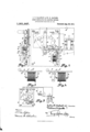
- Figure 1 is a front elevation of a rheostat constructed in accordance with the most improved form of our invention, and connected to a series motor; 2 is a side elevation of the front plate thereof, partly in section on the plane 2; Figs. 3 and 4 show other forms or embodiments of the essential elements which may be used in place of the form used in Fig. 1, and Fig. 5 is a diagrammatic view showing the method of connection for shunt-motors.
- the rheostat as shown is of ordinary con struction having a base-plate or front-plate a of suitable insulating material such as slate, marble, porcelain, etc, secured by screw 7) to the rheostat proper.
- a post 0 which forms a pivot for the contact-arm (Z, which latter swings 'over an are limited by stop-pins e and is provided with resilient contact-strips f and 9 making contact respectively with an arcuate plate 71. and a series of disks or but tons 2' between which are connected the sev eral lengths of resistance-wire, as commonly used in this type of apparatus.
- a coiled torsion-spring j is mounted in the hub of the arm (Z, and being connected at one end to the pin 0 and at the other end to the hub of the arm (Z, acts to swing said arm into the starting position, shown in dotted lines in Fig. 1, when released.
- the usual terminal posts 7r together with the leads Z of an electric circuit divided by a cutout switch m, and having the armature 0c of an electric motor in circuit therewith.
- the rheostat is of the ordinary and usual type, forming no part of our invention.
- an electromagnet which consists of a coil n having a central core 0 and an L-shaped yoke 79 connected at one end with the end of the core 0. Adjacent to this magnet is arranged an armature Z which is pivoted on a pin a.
- a sliding bar 9 Disposed to reciprocate in a direction at right angles to the arm (Z is a sliding bar 9, which is connected thereto by a link 9 which is pivoted to the arm (Z upon a pin (Z Mounted above the bar q is a slotted post It carrying an adjustable edge bit 1" which may be adjusted and clamped in position by a setscrew T and this bit is adapted to engage in one of a series of notches Q2 on the upper side of the arm
- the notches are preferably V-shaped, having their righthand surfaces of the same angle as the corresponding face of the edge of the bit 1, and sufficiently steep to enable the bar to be held in engagement by means to be described.
- This means consists of a leafor bar-spring .2 which is secured to the armature Z by screws 2 said spring pressing the bar 9 upwar lly against the edge of the bit 1" as shown, whenever the magnet coil a is energized so as to attract the armature Z.
- the arm 1 is loosely guided so as to have a free vertical movement sufficient to enable the notches g to engage with or clear the edge of the bit r by means of a slotted post Q3, in the slot 9* of which the bar ⁇ I freely travels, and a pin g which is placed below the opposite end of the bar.
- the magnet-coil n is inserted between one of the terminals and the rheostat-coils, as shown, by the leads 8, the opposite terminal 70 being permanently connected to the plate 72. and to the switch in through the motor 50 by leads Z or in any other preferred manner. hen the current is thrown on, the magnet will attract the armature Z, and cause the spring 2 to press the arm Q against the bit 7. As the arm (Z is moved over toward the right by successive steps, the edge of the bit engages the successive notches g and the strength of the magnet increases with the current, thus balancing the increasing force of the spring 7'.
- the angle of the notches 9 and tooth 79 is such that the attraction of the magnet is sufficient to hold the armature in whatever notch it may engage in against the force of the spring j, but as soon as the circuit is broken, as by opening the switch m, the attraction of the magnet ceases, and the armature, being no longer held thereby, is released and allows the arm to be swung back to the starting-point by the spring
- Fig. 3 a somewhat simpler arrangement is shown, the pole-sh oes 25 being in this case directly connected with the sliding bar Q which acts as its armature.
- Fig. 4- the arrangement is similar to the Fig. 3, except that the tooth t is omitted and an independent tooth a mounted upon a separate member a substituted therefor. This leaves a small but constant air-break in the magnetic circuit which prevents the bar 9 from possible sticking from residual magnetism.
- Fig. 5 illustrates the method of connection, as commonly used for shunt-motors.
- three terminal-posts 70 are provided, two for the armature and one for the field-current, the former being connected by leads Z to the contact-strip h and the extreme right-hand contact-button 6, while the magnet-coil a is connected by leads .9 to the third contact-post Z7 and to the contact-button i in connection with the resistance-wire at the other end of the resistance, as shown.
- the motor is represented by an armature 1) and field w, the former being connected in the usual manner by leads Z through the switch m to the first two terminal posts 70, and the latter by lead y to the third terminal post it.
- a contact-arm means for resiliently moving it into the starting position, an electromagnet, a sliding-bar guided to reciprocate in. an endwise direction and having a plurality of notches on its upper side, an intermediate member connecting said bar with said arm, and a toothed member with which said notches are adapted to engage in the respective positions of said arm; said electromagnet being operatively connected with said arm and adapted when energized to hold said member in engagement with said notches.
- a contact-arm means for returning it when released to the starting position
- a sliding bar guided to reciprocate endwise and having some freedom of transverse movement
- a link connecting said bar with said arm
- a fixed member opposite said bar said bar and fixed member having a plurality of oblique inter-engaging surfaces which are adapted to become engaged when said bar is moved laterally to one side and to become disengaged when the bar is moved laterally to the other side, and an electromagnet adapted when energized to move said bar laterally to the engaging side.
- a movable contactmember a fixed element, a member adapted to slide over said fixed element, means connecting said last-named member with said contact-member, said sliding member and fixed element having interengaging surfaces oblique to the direction of movement of said sliding-member at points corresponding to difierent steps of the regulation, means adapted to return said movable contactmember to its starting position when released and to overcome the action of said interengaging surfaces when not otherwise held in engagement, an electromagnet, a pivoted armature for said electromagnet and a spring mounted on said armature and adapted when said armature is attracted to said magnet to press said sliding member against said fixed element.
- a regulator the combination with a pivoted contact-arm, a sliding-bar guided to slide endwise and having a plurality of notches in one side and a certain lateral movement, a link connecting said bar with said arm, an edged bit on one side of said bar and adapted to engage in any of said notches, an electromagnet connected in circuit with the regulator, a pivoted armature for said electromagnet, and means yieldingly connecting said armature with said bar in such manner that when said armature is attracted said bar is pressed against said bit.
- a regulator the combination with a pivoted contact-arm, a sliding-bar guided to slide endwise and having a plurality of notches in one side and a certain lateral movement, a link connecting said bar with said arm, an edged bit on one side of said bar and adapted to engage in any of said notches, an electromagnet connected in circuit with the regulator, a pivoted armature for said electromagnet, and a spring mounted on said armature and acting to press said bar laterally against said bit when said armature is attracted by said magnet.
Landscapes
- Physics & Mathematics (AREA)
- Electromagnetism (AREA)
- Mechanical Control Devices (AREA)
Description
J. T. KALWEIT & W. H. GAULKE.
SPEED REGULATOR FOR ELECTRIC MOTORS.
APPLICATION FILED OUT. 20, 1910.
1 ,OO1,647., Patented Aug. 29, 1911.
iiiiii Hi iiiii iiiiiii rim lllllll mu mmn Ill llllllll ll Ii iii;
Iii
Ill lllllllllllll UNITED STATES PATENT OFFTCE.
JULIUS T. KALIVEIT AND WILLIAM: H. GAULKE, OF MILFTAUKEE, WISCONSIN, ASSIGN- ORS TO INDEPENDENT ELECTRIC MANUFACTURING COMPANY, A CORPORATION OF WISCONSIN.
SPEED-REGULATOR FOR ELECTRIC MOTORS.
Specification of Letters Patent.
Application filed October 20, 1910.
To all whom it may concern;
Be it known that we, JULIUs T. Knnwnrr and TVILLIAM H. GAULKE, both of Milwaukee, Wisconsin, have invented a Speed- Regulator for Electric Motors, of which the following is a specification.
This invention consists of a speed regulator for electric motors having novel means for holding it electromagnetically at any position of the contact-arm.
In general, our invention consists in providing an electromagnet which is energized by the circuit-current of the motor, and in conjunction therewith a sliding-bar which is connected with the contactarm of the rheostat, said sliding-bar having a series of notches corresponding to the several stops or points of the rheostat in position for several engagement with a tooth element when the contact-arm is on the corresponding step or-point; the notches being held in engagement with said tooth element by the attraction of the magnet and being released therefrom to permit the contact-arm to be re turned to the starting-point whenever the current ceases, as by opening the mainswitch of the circuit.
In the preferred form of our invention, the sliding-bar is not directly attracted by the magnet, but is actuated by the medium of a secondary bar which is directly attracted by the magnet and is operatively connected to the first bar by resilient means such as a spring.
Our invention further consists in the constructions and combinations which will be hereinafter described and specifically set forth in the claims.
For the better understanding of our invention, we have illustrated the same in various embodiments in the accompanying drawings, wherein Figure 1 is a front elevation of a rheostat constructed in accordance with the most improved form of our invention, and connected to a series motor; 2 is a side elevation of the front plate thereof, partly in section on the plane 2; Figs. 3 and 4 show other forms or embodiments of the essential elements which may be used in place of the form used in Fig. 1, and Fig. 5 is a diagrammatic view showing the method of connection for shunt-motors.
The reference letters refer each to the same part in each figure of the drawings.
Patented Aug. 29, 1911.
Serial No. 588.041.
The rheostat as shown is of ordinary con struction having a base-plate or front-plate a of suitable insulating material such as slate, marble, porcelain, etc, secured by screw 7) to the rheostat proper. On this plate is mounted a post 0 which forms a pivot for the contact-arm (Z, which latter swings 'over an are limited by stop-pins e and is provided with resilient contact-strips f and 9 making contact respectively with an arcuate plate 71. and a series of disks or but tons 2' between which are connected the sev eral lengths of resistance-wire, as commonly used in this type of apparatus. A coiled torsion-spring j is mounted in the hub of the arm (Z, and being connected at one end to the pin 0 and at the other end to the hub of the arm (Z, acts to swing said arm into the starting position, shown in dotted lines in Fig. 1, when released. We have also shown for purposes of illustration the usual terminal posts 7r: together with the leads Z of an electric circuit divided by a cutout switch m, and having the armature 0c of an electric motor in circuit therewith. As thus far described the rheostat is of the ordinary and usual type, forming no part of our invention.
At one side of the arm (Z is mounted an electromagnet which consists of a coil n having a central core 0 and an L-shaped yoke 79 connected at one end with the end of the core 0. Adjacent to this magnet is arranged an armature Z which is pivoted on a pin a. Disposed to reciprocate in a direction at right angles to the arm (Z is a sliding bar 9, which is connected thereto by a link 9 which is pivoted to the arm (Z upon a pin (Z Mounted above the bar q is a slotted post It carrying an adjustable edge bit 1" which may be adjusted and clamped in position by a setscrew T and this bit is adapted to engage in one of a series of notches Q2 on the upper side of the arm The notches are preferably V-shaped, having their righthand surfaces of the same angle as the corresponding face of the edge of the bit 1, and sufficiently steep to enable the bar to be held in engagement by means to be described. This means consists of a leafor bar-spring .2 which is secured to the armature Z by screws 2 said spring pressing the bar 9 upwar lly against the edge of the bit 1" as shown, whenever the magnet coil a is energized so as to attract the armature Z.
The arm 1 is loosely guided so as to have a free vertical movement sufficient to enable the notches g to engage with or clear the edge of the bit r by means of a slotted post Q3, in the slot 9* of which the bar {I freely travels, and a pin g which is placed below the opposite end of the bar.
The magnet-coil n is inserted between one of the terminals and the rheostat-coils, as shown, by the leads 8, the opposite terminal 70 being permanently connected to the plate 72. and to the switch in through the motor 50 by leads Z or in any other preferred manner. hen the current is thrown on, the magnet will attract the armature Z, and cause the spring 2 to press the arm Q against the bit 7. As the arm (Z is moved over toward the right by successive steps, the edge of the bit engages the successive notches g and the strength of the magnet increases with the current, thus balancing the increasing force of the spring 7'. The angle of the notches 9 and tooth 79 is such that the attraction of the magnet is sufficient to hold the armature in whatever notch it may engage in against the force of the spring j, but as soon as the circuit is broken, as by opening the switch m, the attraction of the magnet ceases, and the armature, being no longer held thereby, is released and allows the arm to be swung back to the starting-point by the spring In Fig. 3 a somewhat simpler arrangement is shown, the pole-sh oes 25 being in this case directly connected with the sliding bar Q which acts as its armature. The position of the bar 1 is reversed so that the notches come on the under side, and the magnet coil 91 is mounted on a core having two poleshoes 2,, one of which has a tooth t, which takes the place of the bit r. In this case the guiding-post g and pin 1 are dispensed with and a single pin 79 substituted there for. It will be seen that this acts in a similar manner with the form shown in Fig. 1, the electromagnet in this case holding the bar-armature 9 directly in engagement with the tooth t.
In Fig. 4- the arrangement is similar to the Fig. 3, except that the tooth t is omitted and an independent tooth a mounted upon a separate member a substituted therefor. This leaves a small but constant air-break in the magnetic circuit which prevents the bar 9 from possible sticking from residual magnetism.
Fig. 5 illustrates the method of connection, as commonly used for shunt-motors. In this case three terminal-posts 70 are provided, two for the armature and one for the field-current, the former being connected by leads Z to the contact-strip h and the extreme right-hand contact-button 6, while the magnet-coil a is connected by leads .9 to the third contact-post Z7 and to the contact-button i in connection with the resistance-wire at the other end of the resistance, as shown. The motor is represented by an armature 1) and field w, the former being connected in the usual manner by leads Z through the switch m to the first two terminal posts 70, and the latter by lead y to the third terminal post it.
We wish it understood that our invention is not limited to the use of all the above described features and constructions, for some may be omitted and others may be varied or modified in various ways, as will readily ocour to those skilled in the art.
Having thus described our invention, what we claim as new and desire to secure by Letters Patent is:
1. In a regulator, the combination of a contact-arm, means for resiliently moving it into the starting position, an electromagnet, a sliding-bar guided to reciprocate in. an endwise direction and having a plurality of notches on its upper side, an intermediate member connecting said bar with said arm, and a toothed member with which said notches are adapted to engage in the respective positions of said arm; said electromagnet being operatively connected with said arm and adapted when energized to hold said member in engagement with said notches.
2. In a regulator, the combination of a contact-arm, means for returning it when released to the starting position, a sliding bar guided to reciprocate endwise and having some freedom of transverse movement, a link connecting said bar with said arm, a fixed member opposite said bar, said bar and fixed member having a plurality of oblique inter-engaging surfaces which are adapted to become engaged when said bar is moved laterally to one side and to become disengaged when the bar is moved laterally to the other side, and an electromagnet adapted when energized to move said bar laterally to the engaging side.
3. The combination of a movable contactmember, a fixed element, a member adapted to slide over said fixed element, a link con necting said last-named membe with said contact-member, said sliding member and fixed element having interengaging surfaces oblique to the direction of movement of said sliding-member at points corresponding to different steps of the regulation, means adapted to return said movable contactmember to its starting position when released and to overcome the action of said interengaging surfaces when not otherwise held in engagement, and an electromagnet arranged to hold said interengaging surfaces in engagement, the weight of said sliding member acting to withdraw it from engagement with said fixed element.
4. The combination of a movable contactmember, a fixed element, a member adapted to slide over said fixed element, means connecting said last-named member with said contact-member, said sliding member and fixed element having interengaging surfaces oblique to the direction of movement of said sliding-member at points corresponding to different steps of the regulation, means adapted to return said movable contact-member to its starting position when released and to overcome the action of said interengaging surfaces when not otherwise held in engagement, an electromagnet, an armature for said magnet, and a spring connected with said armature and actuated thereby to press said sliding-member against said fixed element when said electromagnet is energized.
5. The combination of a movable contactmember, a fixed element, a member adapted to slide over said fixed element, means connecting said last-named member with said contact-member, said sliding member and fixed element having interengaging surfaces oblique to the direction of movement of said sliding-member at points corresponding to difierent steps of the regulation, means adapted to return said movable contactmember to its starting position when released and to overcome the action of said interengaging surfaces when not otherwise held in engagement, an electromagnet, a pivoted armature for said electromagnet and a spring mounted on said armature and adapted when said armature is attracted to said magnet to press said sliding member against said fixed element.
6. In a regulator, the combination with a pivoted contact-arm, a sliding-bar guided to slide endwise and having a plurality of notches in one side and a certain lateral movement, a link connecting said bar with said arm, an edged bit on one side of said bar and adapted to engage in any of said notches, an electromagnet connected in circuit with the regulator, a pivoted armature for said electromagnet, and means yieldingly connecting said armature with said bar in such manner that when said armature is attracted said bar is pressed against said bit.
7. In a regulator, the combination with a pivoted contact-arm, a sliding-bar guided to slide endwise and having a plurality of notches in one side and a certain lateral movement, a link connecting said bar with said arm, an edged bit on one side of said bar and adapted to engage in any of said notches, an electromagnet connected in circuit with the regulator, a pivoted armature for said electromagnet, and a spring mounted on said armature and acting to press said bar laterally against said bit when said armature is attracted by said magnet.
In witness whereof we have hereunto set our hands in the presence of two witnesses.
JUL. 'I. KALWVEII. WM. H. GAULKE. Witnesses:
FRANK KRAEMER, HERBERT FEERIOK.
Copies of this patent may be obtained for five cents each, by addressing the Commissioner of Patents, Washington, D. C.
Priority Applications (1)
| Application Number | Priority Date | Filing Date | Title |
|---|---|---|---|
| US58804110A US1001647A (en) | 1910-10-20 | 1910-10-20 | Speed-regulator for electric motors. |
Applications Claiming Priority (1)
| Application Number | Priority Date | Filing Date | Title |
|---|---|---|---|
| US58804110A US1001647A (en) | 1910-10-20 | 1910-10-20 | Speed-regulator for electric motors. |
Publications (1)
| Publication Number | Publication Date |
|---|---|
| US1001647A true US1001647A (en) | 1911-08-29 |
Family
ID=3069972
Family Applications (1)
| Application Number | Title | Priority Date | Filing Date |
|---|---|---|---|
| US58804110A Expired - Lifetime US1001647A (en) | 1910-10-20 | 1910-10-20 | Speed-regulator for electric motors. |
Country Status (1)
| Country | Link |
|---|---|
| US (1) | US1001647A (en) |
-
1910
- 1910-10-20 US US58804110A patent/US1001647A/en not_active Expired - Lifetime
Similar Documents
| Publication | Publication Date | Title |
|---|---|---|
| US983976A (en) | Motor-controlling device. | |
| US1001647A (en) | Speed-regulator for electric motors. | |
| US1582987A (en) | Remote-control electric switch | |
| US820119A (en) | Automatic electric circuit changer or switch. | |
| US731375A (en) | Electric controller for electric motors. | |
| US497144A (en) | Pedal switch foe electric motors | |
| US589582A (en) | Thur w | |
| US1208576A (en) | Electric switch. | |
| US518404A (en) | Electric starting-switch | |
| US603524A (en) | coachman | |
| US910478A (en) | Rheostat. | |
| US664986A (en) | Electric switch. | |
| US650582A (en) | Rheostat-switch. | |
| US1019425A (en) | Time and current limit relay. | |
| US663207A (en) | Means for starting or stopping electric motors. | |
| US704447A (en) | Protective operating device for electric motors. | |
| US1234542A (en) | Feed-through switch. | |
| US516651A (en) | Automatic speed-regulator for electric motors | |
| US1008811A (en) | Starter and regulator for compound motors. | |
| US1769674A (en) | Relay | |
| US519715A (en) | Hand regulator or switch for motors | |
| US549464A (en) | Electrical dental engine | |
| US1066677A (en) | Electromagnet-switch. | |
| US482420A (en) | Adjustable thermostat | |
| US264982A (en) | weston |