US10015617B2 - Method and apparatus for an ultrasonic emitter system floor audio unit - Google Patents
Method and apparatus for an ultrasonic emitter system floor audio unit Download PDFInfo
- Publication number
- US10015617B2 US10015617B2 US15/451,626 US201715451626A US10015617B2 US 10015617 B2 US10015617 B2 US 10015617B2 US 201715451626 A US201715451626 A US 201715451626A US 10015617 B2 US10015617 B2 US 10015617B2
- Authority
- US
- United States
- Prior art keywords
- listener
- ultrasonic
- audio
- location
- operable
- Prior art date
- Legal status (The legal status is an assumption and is not a legal conclusion. Google has not performed a legal analysis and makes no representation as to the accuracy of the status listed.)
- Active
Links
- 238000000034 method Methods 0.000 title claims abstract description 33
- 230000001953 sensory effect Effects 0.000 claims abstract 7
- 230000008569 process Effects 0.000 claims description 16
- 230000000007 visual effect Effects 0.000 claims description 10
- 238000012545 processing Methods 0.000 claims description 9
- 239000010408 film Substances 0.000 description 25
- 239000000463 material Substances 0.000 description 18
- 230000001681 protective effect Effects 0.000 description 18
- 239000004020 conductor Substances 0.000 description 16
- 230000006870 function Effects 0.000 description 16
- 239000012811 non-conductive material Substances 0.000 description 12
- 210000005069 ears Anatomy 0.000 description 11
- 230000003287 optical effect Effects 0.000 description 9
- 239000003550 marker Substances 0.000 description 7
- 230000005236 sound signal Effects 0.000 description 7
- 238000004804 winding Methods 0.000 description 5
- 229910052782 aluminium Inorganic materials 0.000 description 4
- XAGFODPZIPBFFR-UHFFFAOYSA-N aluminium Chemical compound [Al] XAGFODPZIPBFFR-UHFFFAOYSA-N 0.000 description 4
- 238000004590 computer program Methods 0.000 description 4
- 230000007246 mechanism Effects 0.000 description 4
- 239000004033 plastic Substances 0.000 description 4
- OKTJSMMVPCPJKN-UHFFFAOYSA-N Carbon Chemical compound [C] OKTJSMMVPCPJKN-UHFFFAOYSA-N 0.000 description 3
- 239000011554 ferrofluid Substances 0.000 description 3
- 239000011521 glass Substances 0.000 description 3
- 229910021389 graphene Inorganic materials 0.000 description 3
- 230000008901 benefit Effects 0.000 description 2
- 238000013461 design Methods 0.000 description 2
- 230000000694 effects Effects 0.000 description 2
- 238000005516 engineering process Methods 0.000 description 2
- 239000010409 thin film Substances 0.000 description 2
- 238000012546 transfer Methods 0.000 description 2
- 241000217377 Amblema plicata Species 0.000 description 1
- 229920002799 BoPET Polymers 0.000 description 1
- 239000005041 Mylar™ Substances 0.000 description 1
- -1 Polypropylene Polymers 0.000 description 1
- 239000004743 Polypropylene Substances 0.000 description 1
- 229920009405 Polyvinylidenefluoride (PVDF) Film Polymers 0.000 description 1
- 238000013459 approach Methods 0.000 description 1
- 230000002238 attenuated effect Effects 0.000 description 1
- 238000006243 chemical reaction Methods 0.000 description 1
- 239000002131 composite material Substances 0.000 description 1
- 235000009508 confectionery Nutrition 0.000 description 1
- 238000010276 construction Methods 0.000 description 1
- 239000002537 cosmetic Substances 0.000 description 1
- 230000001419 dependent effect Effects 0.000 description 1
- 238000001514 detection method Methods 0.000 description 1
- 239000004744 fabric Substances 0.000 description 1
- 238000010348 incorporation Methods 0.000 description 1
- 230000010365 information processing Effects 0.000 description 1
- 230000010354 integration Effects 0.000 description 1
- 230000003993 interaction Effects 0.000 description 1
- 229910052751 metal Inorganic materials 0.000 description 1
- 239000002184 metal Substances 0.000 description 1
- 230000003278 mimic effect Effects 0.000 description 1
- 238000012986 modification Methods 0.000 description 1
- 230000004048 modification Effects 0.000 description 1
- 229920003223 poly(pyromellitimide-1,4-diphenyl ether) Polymers 0.000 description 1
- 229920001155 polypropylene Polymers 0.000 description 1
- 230000001902 propagating effect Effects 0.000 description 1
- 230000004044 response Effects 0.000 description 1
- 229920006395 saturated elastomer Polymers 0.000 description 1
Images


Classifications
-
- H—ELECTRICITY
- H04—ELECTRIC COMMUNICATION TECHNIQUE
- H04S—STEREOPHONIC SYSTEMS
- H04S7/00—Indicating arrangements; Control arrangements, e.g. balance control
- H04S7/30—Control circuits for electronic adaptation of the sound field
- H04S7/302—Electronic adaptation of stereophonic sound system to listener position or orientation
- H04S7/303—Tracking of listener position or orientation
-
- G—PHYSICS
- G06—COMPUTING; CALCULATING OR COUNTING
- G06F—ELECTRIC DIGITAL DATA PROCESSING
- G06F3/00—Input arrangements for transferring data to be processed into a form capable of being handled by the computer; Output arrangements for transferring data from processing unit to output unit, e.g. interface arrangements
- G06F3/01—Input arrangements or combined input and output arrangements for interaction between user and computer
- G06F3/03—Arrangements for converting the position or the displacement of a member into a coded form
-
- G—PHYSICS
- G10—MUSICAL INSTRUMENTS; ACOUSTICS
- G10K—SOUND-PRODUCING DEVICES; METHODS OR DEVICES FOR PROTECTING AGAINST, OR FOR DAMPING, NOISE OR OTHER ACOUSTIC WAVES IN GENERAL; ACOUSTICS NOT OTHERWISE PROVIDED FOR
- G10K11/00—Methods or devices for transmitting, conducting or directing sound in general; Methods or devices for protecting against, or for damping, noise or other acoustic waves in general
- G10K11/18—Methods or devices for transmitting, conducting or directing sound
- G10K11/26—Sound-focusing or directing, e.g. scanning
- G10K11/35—Sound-focusing or directing, e.g. scanning using mechanical steering of transducers or their beams
- G10K11/352—Sound-focusing or directing, e.g. scanning using mechanical steering of transducers or their beams by moving the transducer
-
- G—PHYSICS
- G10—MUSICAL INSTRUMENTS; ACOUSTICS
- G10K—SOUND-PRODUCING DEVICES; METHODS OR DEVICES FOR PROTECTING AGAINST, OR FOR DAMPING, NOISE OR OTHER ACOUSTIC WAVES IN GENERAL; ACOUSTICS NOT OTHERWISE PROVIDED FOR
- G10K15/00—Acoustics not otherwise provided for
- G10K15/02—Synthesis of acoustic waves
-
- H—ELECTRICITY
- H04—ELECTRIC COMMUNICATION TECHNIQUE
- H04B—TRANSMISSION
- H04B11/00—Transmission systems employing sonic, ultrasonic or infrasonic waves
-
- H—ELECTRICITY
- H04—ELECTRIC COMMUNICATION TECHNIQUE
- H04R—LOUDSPEAKERS, MICROPHONES, GRAMOPHONE PICK-UPS OR LIKE ACOUSTIC ELECTROMECHANICAL TRANSDUCERS; DEAF-AID SETS; PUBLIC ADDRESS SYSTEMS
- H04R5/00—Stereophonic arrangements
- H04R5/02—Spatial or constructional arrangements of loudspeakers
-
- H—ELECTRICITY
- H04—ELECTRIC COMMUNICATION TECHNIQUE
- H04R—LOUDSPEAKERS, MICROPHONES, GRAMOPHONE PICK-UPS OR LIKE ACOUSTIC ELECTROMECHANICAL TRANSDUCERS; DEAF-AID SETS; PUBLIC ADDRESS SYSTEMS
- H04R5/00—Stereophonic arrangements
- H04R5/04—Circuit arrangements, e.g. for selective connection of amplifier inputs/outputs to loudspeakers, for loudspeaker detection, or for adaptation of settings to personal preferences or hearing impairments
-
- H—ELECTRICITY
- H04—ELECTRIC COMMUNICATION TECHNIQUE
- H04S—STEREOPHONIC SYSTEMS
- H04S5/00—Pseudo-stereo systems, e.g. in which additional channel signals are derived from monophonic signals by means of phase shifting, time delay or reverberation
- H04S5/005—Pseudo-stereo systems, e.g. in which additional channel signals are derived from monophonic signals by means of phase shifting, time delay or reverberation of the pseudo five- or more-channel type, e.g. virtual surround
-
- H—ELECTRICITY
- H04—ELECTRIC COMMUNICATION TECHNIQUE
- H04S—STEREOPHONIC SYSTEMS
- H04S7/00—Indicating arrangements; Control arrangements, e.g. balance control
- H04S7/30—Control circuits for electronic adaptation of the sound field
- H04S7/301—Automatic calibration of stereophonic sound system, e.g. with test microphone
-
- H—ELECTRICITY
- H04—ELECTRIC COMMUNICATION TECHNIQUE
- H04R—LOUDSPEAKERS, MICROPHONES, GRAMOPHONE PICK-UPS OR LIKE ACOUSTIC ELECTROMECHANICAL TRANSDUCERS; DEAF-AID SETS; PUBLIC ADDRESS SYSTEMS
- H04R2205/00—Details of stereophonic arrangements covered by H04R5/00 but not provided for in any of its subgroups
- H04R2205/024—Positioning of loudspeaker enclosures for spatial sound reproduction
-
- H—ELECTRICITY
- H04—ELECTRIC COMMUNICATION TECHNIQUE
- H04R—LOUDSPEAKERS, MICROPHONES, GRAMOPHONE PICK-UPS OR LIKE ACOUSTIC ELECTROMECHANICAL TRANSDUCERS; DEAF-AID SETS; PUBLIC ADDRESS SYSTEMS
- H04R2217/00—Details of magnetostrictive, piezoelectric, or electrostrictive transducers covered by H04R15/00 or H04R17/00 but not provided for in any of their subgroups
- H04R2217/03—Parametric transducers where sound is generated or captured by the acoustic demodulation of amplitude modulated ultrasonic waves
-
- H—ELECTRICITY
- H04—ELECTRIC COMMUNICATION TECHNIQUE
- H04S—STEREOPHONIC SYSTEMS
- H04S2400/00—Details of stereophonic systems covered by H04S but not provided for in its groups
- H04S2400/05—Generation or adaptation of centre channel in multi-channel audio systems
Definitions
- aspects of the present application relate to audio systems, particularly systems that may generate directional sound utilizing ultrasonic emitters. More specifically, various implementations in accordance with the present disclosure relate to systems and methods for ultrasonic emitter system floor audio units.
- FIG. 1 illustrates an example ultrasonic system that is operable to generate ultrasonic signals, in accordance with an example embodiment of the present disclosure.
- FIG. 2 illustrates an example circuit for an ultrasonic device that is operable to generate ultrasonic signals, in accordance with an example embodiment of the present disclosure.
- FIG. 3 illustrates an example system that utilizes an ultrasonic emitter comprising a film with a conductive layer to generate ultrasonic signals in an electrostatic arrangement, in accordance with an example embodiment of the present disclosure.
- FIG. 4 illustrates an example configuration of an ultrasonic emitter comprising a film with a conductive layer to generate ultrasonic signals in an electrostatic arrangement, in accordance with an example embodiment of the present disclosure.
- FIG. 5A illustrates an example transformer coupled to an ultrasonic emitter that utilizes a film with a conductive layer with a conductive layer, in accordance with an example embodiment of the present disclosure.
- FIG. 5B illustrates an example self-bias circuit for use in ultrasonic emitters, in accordance with various example embodiments of the present disclosure.
- FIG. 6A illustrates an example ultrasonic emitter system floor audio unit, in accordance with an example embodiment of the present disclosure.
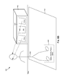
- FIG. 6B illustrates an example use scenario of a listener standing at the optimal standing position in front an ultrasonic emitter system floor audio unit that projects sound upwards, in accordance with an example embodiment of the present disclosure.
- FIG. 6C illustrates an example ultrasonic emitter system floor audio unit comprising integrated sensors, in accordance with an example embodiment of the present disclosure.
- FIG. 6D illustrates an example ultrasonic emitter system floor audio unit comprising an integrated camera, in accordance with an example embodiment of the present disclosure.
- FIG. 7 is a flow chart illustrating an example process for generating hypersound audio from an ultrasonic emitter system floor audio unit, in accordance with various example embodiments of the present disclosure.
- FIG. 8 is a flow chart illustrating an example process for generating hypersound audio from an ultrasonic emitter system floor audio unit, in accordance with various example embodiments of the present disclosure.
- FIG. 9 is a flow chart illustrating an example process for hypersound audio from an ultrasonic emitter system floor audio unit, in accordance with various example embodiments of the present disclosure.
- circuits and circuitry refer to physical electronic components (“hardware”) and any software and/or firmware (“code”) which may configure the hardware, be executed by the hardware, and or otherwise be associated with the hardware.
- a particular processor and memory may comprise a first “circuit” when executing a first plurality of lines of code and may comprise a second “circuit” when executing a second plurality of lines of code.
- and/or means any one or more of the items in the list joined by “and/or”.
- x and/or y means any element of the three-element set ⁇ (x), (y), (x, y) ⁇ .
- x and/or y means “one or both of x and y.”
- x, y, and/or z means any element of the seven-element set ⁇ (x), (y), (z), (x, y), (x, z), (y, z), (x, y, z) ⁇ .
- x, y and/or z means “one or more of x, y and z.”
- block and “module” refer to functions than can be performed by one or more circuits.
- example means serving as a non-limiting example, instance, or illustration.
- circuitry is “operable” to perform a function whenever the circuitry comprises the necessary hardware and code (if any is necessary) to perform the function, regardless of whether performance of the function is disabled or not enabled (e.g., by a user-configurable setting, factory trim, etc.).
- FIG. 1 illustrates an example ultrasonic system that is operable to generate ultrasonic signals, in accordance with an example embodiment of the present disclosure. Shown in FIG. 1 is an ultrasonic system 100 , which may comprise an audio source 102 and pair of ultrasonic emitters 104 a and 104 b.
- the audio source 102 may comprise suitable circuitry operable to receive, generate, and/or process audio signals for output to one or more conventional speakers and/or directional ultrasonic emitters.
- the audio source 102 may be operable to receive, generate, and/or process audio signals for output to the ultrasonic emitters 104 a and 104 b , which may be coupled to the audio source 102 via links 103 a and 103 b .
- the system is assumed to be a HyperSound System (HSS) that uses ultrasonic emitters for projecting directional ultrasonic signals as described, for example, in U.S. Pat. Nos.
- HSS HyperSound System
- the audio source 102 may be, for example, a dedicated audio receiver/processor, a multi-function set-top-box (e.g., a cable television set-top-box or Direct Broadcast Satellite set-top box), a computer (e.g., Windows, MAC, or Linux based) with sound processing and output capabilities, or the like.
- Each of the links 103 a and 103 b may be a wired, wireless, and/or optical link.
- Links 103 a , 103 b may carry an electrical and/or optical representation of an audio-band signal.
- Each of the ultrasonic emitters 104 a and 104 b may be operable to receive an audio-band signal from its respective one of links 103 a and 103 b and convert the audio-band to ultrasonic waves transmitted in a highly-focused air beam (shown as air beams 106 a and 106 b ).
- audio source 102 may comprise suitable circuitry for providing ultrasonic modulation, and links 103 a and 103 b may carry an electrical and/or optical representation of an ultrasonic signal.
- the propagation of the ultrasonic signal in air may effectively demodulate the ultrasonic signals with respect to the listener; thus, an active demodulation device may not be required.
- the corresponding demodulated audio-band signal may be audible to the listener 110 that is within the air-beams, namely 106 a and 106 b .
- the corresponding demodulated audio-band signals may be greatly attenuated to the listener 112 .
- the emitters 104 a and 104 b may be mounted in any desired location. For example, they may be mounted to either side of a television as conventional left and right channels speakers are typically mounted. As another example, the speakers may be mounted in an apparatus that places them close to the listeners ears (e.g., mounted to a chair that the listener sits in) to achieve sound quality similar to headphones but without having headphones actually touching the listeners head.
- aspects of this disclosure improve the ability of the system shown in FIG. 1 to create a three-dimensional sound effect whereby, although the audio-band signal is emitted from only the two emitters 104 a and 104 b , the listener 110 perceives various sounds in the audio as emanating from various locations in the 3D space around him/her (i.e., virtual surround sound).
- the exemplary system that is illustrated in FIG. 1 may also be operable to generate a three-dimensional sound and may comprise one or more ultrasonic emitters that comprise glass, aluminum, graphene, ferro-fluid, and/or other material, which may be operable to generate a ultrasonic output.
- FIG. 2 illustrates an example circuit for an ultrasonic device that is operable to generate ultrasonic signals, in accordance with an example embodiment of the present disclosure. Shown in FIG. 2 is an ultrasonic device 200 .
- the ultrasonic device 200 may comprise suitable circuitry for generating and/or outputting ultrasonic signals.
- the ultrasonic device 200 may comprise an audio source 202 , processing circuits 204 a and 204 b , ultrasonic generators/emitters 208 a and 208 b , an audio processing circuit 210 , and speaker 212 .
- the audio source 202 may comprise, for example, memory for storing audio files and circuitry for reading the audio files and generating electrical and/or optical audio-band signals.
- the audio source 202 may comprise, for example, circuitry for receiving and processing audio signals (e.g., circuitry for demodulating, decoding, etc. to recover an audio band signal from a modulated carrier) that were transmitted over a wired, wireless, or optical link.
- the audio source 202 may, for example, reside in the receiver 102 of FIG. 1 .
- the audio source 202 outputs a left channel audio signal 203 a and a right channel audio signal 203 b , each of which may be an optical and/or electrical audio-band signal.
- the processing circuits 204 a and 204 b may be operable to process the signal 203 (e.g., perform frequency-dependent amplitude, frequency, and/or phase adjustment) to generate signals 205 a and 205 b .
- the signals 205 a and 205 b may result in a three-dimensional sound effect that the user perceives as more realistic/natural.
- the circuits 204 a and 204 b may be configured to apply a transfer function that may mimic the free space propagation loss that the ultrasonic signals would experience if propagating in free space—as is the manner in which the listener is used to hearing such sounds.
- the circuits 204 a and 204 b may first determine the distance from the emitters 208 a and 208 b to the listener. This distance may be determined in any suitable way. In an example implementation, the distance may be determined by infrared, laser, or other distance measuring sensors integrated into the emitters 208 a and 208 b and/or a receiver, a set-top box, etc. that houses the circuits 202 , 204 , and 210 . In an example implementation, the distance may be input by a user or installer of the system (e.g., via a graphical user interface). Alternatively, the transfer function may represent the frequency response of the emitter.
- the ultrasonic generators/emitters 208 a and 208 b are operable to receive the electrical and/or optical audio band signal 207 a and 207 b and convert them to ultrasonic beams, as described above with respect to FIG. 1 , for example.
- Each of the ultrasonic generators/emitters 208 a and 208 b may comprise a glass, aluminum, ferro-fluid, graphene and/or other type of emitter, which is operable to generate ultrasonic signals.
- circuitry 204 a and 204 b may comprise ultrasonic modulation and links 205 a and 205 b may carry an electrical and/or optical representation of an ultrasonic signal.
- the system of FIG. 2 also comprises a conventional speaker 212 , for use as center channel speaker, which outputs sound wave 214 corresponding to center channel audio.
- the center channel audio frequencies may be below 250-300 Hz.
- the sound wave 214 experiences free space path loss as non-directional audio waves conventionally do.
- the different propagation characteristics of the ultrasonic beams 106 and the sound wave 214 there may cause an unnatural phase and/or time delay between the left and right channel audio arriving via emitters 208 and the center channel audio arriving via speaker 212 .
- the circuitry 210 , 204 a , and 204 b may be operable to process the left, right, and center channel audio such that the center channel arrives at the proper time and/or phase relative to the left and right channels, as would be the case if all three channels were transmitted via conventional speakers.
- FIG. 3 illustrates an example system that utilizes an ultrasonic emitter comprising a film with a conductive layer to generate ultrasonic signals in an electrostatic arrangement, in accordance with an example embodiment of the present disclosure. Shown in FIG. 3 is an ultrasonic emitter 300 which may utilize a film to generate ultrasonic signals.
- the ultrasonic emitter 300 may comprise a conductive backplate 302 , a faceplate, and a protective screen 326 .
- the reference numerals 314 a - 314 i are utilized to define the perimeter of the chamber 316 .
- the ultrasonic emitter 300 described herein may also be referred to as an electrostatic transducer.
- U.S. Pat. Nos. 4,246,449 and 4,081,626 disclose example electrostatic transducers.
- the backplate 302 may comprise suitably rigid material that may be operable to provide a stable support for the emitter structure 300 .
- the backplate 302 may comprise an electrically conductive material.
- the backplate 302 may be coupled to a first electrical lead that may be utilized to bias the ultrasonic emitter 300 .
- the backplate 302 may comprise an aluminum backplate.
- the backplate 302 may comprise a plurality of cavities 308 .
- the cavities 308 may also be referred to as grooves or channels. Notwithstanding, the cavities 308 may be etched or otherwise placed within a front surface of the backplate 302 .
- the peaks 314 a and 314 b resulting from cavities 308 may be utilized to support the faceplate.
- the enclosed structure formed by the peaks 314 a , 314 b , the ridges 314 c , 314 d , 314 e , the bottom of the cavities 314 f , 314 g , 314 h , 314 i and the non-conducting material 312 comprises a chamber 316 .
- the faceplate may comprise a film with a conductive layer or diaphragm that resonates to generate the ultrasonic signal from the ultrasonic emitter 300 .
- the film or diaphragm may comprise, for example, a Mylar or Kapton electrostatic film, Polypropylene film, Polyvinylidene Fluoride (PVDF) film and/or other film or diaphragm suitable for generating ultrasonic signals.
- the faceplate comprising the film or diaphragm may comprise an outer conductive material 310 and a non-conductive material 312 .
- the resonating faceplate 310 comprising the film may be operable to function as a diaphragm that is displaced in order to propagate the corresponding ultrasonic waves.
- the faceplate comprising the film diaphragm may be coupled to a second electrical lead (via the conductive material 310 ) that may be utilized to bias the ultrasonic emitter 300 .
- the non-conductive material 312 may isolate the conductive material 310 from the conductive backplate 302 . In this regard, the non-conductive material 312 may prevent an electrical short from occurring between the faceplate 310 comprising the film and the backplate 302 .
- the conductive material 310 and the non-conductive material 312 are illustrated separately, the disclosure is not limited in this way.
- the conductive material 310 and the non-conductive material 312 together may form an inseparable thin film.
- the geometry and dimension of the ultrasonic emitter 300 and the volume of the chamber 316 may comprise example factors that may affect performance of the emitter. For example, the greater the volume of the chamber 316 , the lower the resonant frequency.
- the number of ridges within the chamber 316 may also affect performance of the emitter. Although three ridges, namely, 314 c , 314 d , 314 e are shown between the peaks 314 a , 314 b , the disclosure is not limited in this regard.
- the angle 320 may be 90 degrees to provide optimal reflection of sonic or ultrasonic waves. An angle of approximately 90 degrees and an optimal number of ridges between the peaks 314 a , 314 b may cause an increase in the resonant frequency of the ultrasonic emitter 300 , which in turn causes an increase in the ultrasonic output of the emitter.
- the protective screen 326 may comprise a suitable material that may protect the ultrasonic emitter 300 or, for example, in particular, the faceplate 310 from damage.
- the material that is utilized for the protective screen 326 may be selected so that it may enhance the ultrasonic output.
- the protective screen 326 may comprise a plastic screen.
- the plastic screen may, for example, function as an impedance matching element that increases the ultrasonic output.
- the plastic screen may double the ultrasonic output power.
- the protective screen 326 may be cosmetic and may also be necessary for standards approval such as Underwriters Laboratory (UL) approval.
- UL Underwriters Laboratory
- FIG. 4 illustrates an example configuration of an ultrasonic emitter comprising a film with a conductive layer to generate ultrasonic signals in an electrostatic arrangement, in accordance with an example embodiment of the present disclosure. Shown in FIG. 4 is an ultrasonic emitter 400 that utilizes a film with a conductive layer to generate ultrasonic signals.
- the ultrasonic emitter 400 may be substantially similar to the ultrasonic emitter 300 , which is shown and described with respect to, for example, FIG. 3 .
- the ultrasonic emitter 400 may comprise, for example, a conductive backplate 402 , and a faceplate.
- the ultrasonic emitter 400 may also comprise a plurality of ridges such as a ridge 414 e , a chamber 416 , and a plurality of cavities 408 on the backplate 402 .
- the structure of the ultrasonic emitter 400 may be substantially similar to the structure of the emitter 300 , which is shown and described with respect to, for example, FIG. 3 .
- the backplate 402 , the peaks 414 a , 414 b , the ridge 414 e , the faceplate, the chamber 416 , and the plurality of cavities 408 may be similar to the corresponding components, namely, the backplate 302 , the peaks 314 a , 314 b , the ridge 314 e , the faceplate, the chamber 316 , and the plurality of cavities 308 , respectively, which are shown and described with respect to, for example, FIG. 3 .
- the faceplate may comprise a film with a conductive layer or diaphragm that resonates to generate the ultrasonic signal from the ultrasonic emitter 400 .
- the faceplate comprising the film or diaphragm may comprise a conductive material 410 and a non-conductive material 412 .
- the design and/or construction of the ultrasonic emitter 400 may be adjusted based on performance criteria or parameters.
- the greater the volume of the faceplate or film for the ultrasonic emitter 400 and/or the greater the volume of the chamber 416 for the ultrasonic emitter 400 the lower the resonant frequency.
- FIG. 4 Various example dimensions are illustrated in FIG. 4 , which may be utilized by the ultrasonic emitter 400 .
- the thin design of the ultrasonic emitter 400 provides greater flexibility.
- the dimension D may represent the difference between the height of the peak 414 b and the height of the ridge 414 e .
- dimension D may be approximately 13 microns or about 0.0005 inch.
- the ultrasonic emitter 400 may be designed such that when the faceplate and the non-conductive material 412 resonates, which are supported by the peaks 414 a , 414 b , the faceplate and the non-conductive material 412 does not touch the ridges such as the ridge 414 e , which are within the chamber 416 .
- the dimension C may represent the distance between the supports or peaks 414 a and 414 b . In an example embodiment of the disclosure, the dimension C may be approximately 0.12 inch.
- the dimensions A, B, and C may be selected so that they are a functionality of the wavelength, ⁇ .
- the dimensions A, B, C may be chosen so as to achieve a resonant frequency that is approximately equivalent to the natural resonant frequency of the film that is utilized for the faceplate, which comprises a film or diaphragm.
- the thickness of the faceplate which comprises a film or diaphragm, may be related to the wavelength of the carrier frequency, f c .
- the thickness of the faceplate comprising the film or diaphragm may be selected so that it provides suitable headroom for the bias voltage. For example, a thickness with 1 ⁇ 2 mil (0.0005 inch) may provide better headroom voltage comparing to a thickness with 1 ⁇ 4 mil.
- the number of ridges between the peaks 414 a , 414 b may affect the resonant frequency of the ultrasonic emitter 400 .
- an optimal number of ridges between the peaks 414 a , 414 b increases the resonant frequency of the ultrasonic emitter 400 .
- the resultant increase in the resonant frequency of the ultrasonic emitter 400 causes an increase in the ultrasonic output of the emitter.
- FIG. 5A illustrates an example transformer coupled to an ultrasonic emitter that utilizes a film with a conductive layer with a conductive layer, in accordance with an example embodiment of the present disclosure. Shown in FIG. 5A is circuitry 500 and an example ultrasonic emitter 501 .
- the circuitry 500 comprises an amplifier 532 , a transformer 534 , and a self-bias circuit 536 .
- the ultrasonic emitter 501 may comprise a conductive backplate 502 and a faceplate.
- the faceplate may comprise, for example, a conductive material 510 and a non-conductive material 512 .
- the conductive material 510 and non-conductive material 512 are illustrated as separate elements, the disclosure is not limited in this way.
- the conductive material 510 and the non-conductive material 512 such that, for example, the conductive material 510 and the non-conductive material 512 together comprise an inseparable thin film.
- the ultrasonic emitter (transducer) 501 may be substantially similar to the ultrasonic emitter 300 , which is shown and described with respect to, for example, FIG. 3 . Accordingly, the backplate 502 and the faceplate may be similar to the corresponding components, namely, the backplate 302 and the faceplate, respectively, which are shown and described with respect to, for example, FIG. 3 .
- the amplifier 532 may comprise, for example, a class D switching amplifier.
- the amplifier 532 and/or the transformer 534 may, for example, reside in the audio receiver/processor 102 of FIG. 1 , or reside in the processing circuit 204 a or 204 b of FIG. 2 .
- the transformer 534 may comprise primary and secondary windings.
- the primary windings of the transformer 534 may be electrically coupled to the amplifier 532 .
- the secondary windings of the transformer 534 may be electrically coupled to the self-bias circuit 536 .
- the self-bias circuit 536 may in turn be coupled to the ultrasonic emitter 501 .
- the transformer 534 may receive an input signal V P from the amplifier 532 via the primary windings of the transformer 534 .
- the input signal V P may be coupled with a DC bias produced by, for example, the self-bias circuit 536 , such that, for example, and an output signal V S from the secondary winding of the transformer 534 may comprise an ultrasonic signal combined with a biasing voltage of, for example, approximately 100-300 volts DC.
- a first output of the self-bias circuit 536 may be electrically coupled to the conductive material 510 of the ultrasonic emitter 501
- a second output of the self-bias circuit 536 may be electrically coupled to the backplate 502 of the ultrasonic emitter 501 .
- the output signal V S may be applied between the conductive material 510 and the backplate 502 .
- FIG. 5B illustrates an example self-bias circuit for use in ultrasonic emitters, in accordance with various example embodiments of the present disclosure. Shown in FIG. 5B is an example self-bias circuit 550 .
- the self-bias circuit 550 is an example embodiment of the self bias circuit 536 , which is shown and described with respect to FIG. 5A .
- a first output of the self-bias circuit 536 may be electrically coupled to the conductive material 510 ( FIG. 5A ) of the ultrasonic emitter 501
- a second output of the self-bias circuit 536 may be electrically coupled to the backplate 502 ( FIG. 5A ) of the ultrasonic emitter 501 ( FIG. 5A ).
- the output signal V S may be applied between the conductive material 510 ( FIG. 5A ) and the backplate 502 ( FIG. 5A ).
- FIG. 6A illustrates an example ultrasonic emitter system floor audio unit, in accordance with an example implementation of the present disclosure. Shown in FIG. 6A is an ultrasonic emitter system floor audio unit 600 .
- the ultrasonic emitter system floor audio unit 600 may comprise an enclosure 602 , a pair of ultrasonic generators/emitters 604 a and 604 b , a sub-woofer 606 , a controller 608 , and a protective material or component 610 .
- the enclosure 602 may function as a housing that encases and protects the components of the ultrasonic emitter system floor audio unit 600 .
- the enclosure 602 may comprise a rigid material such as a plastic, metal and/or a composite material. The dimensions of the enclosure 602 may be kept at a minimum so as to enable the ultrasonic emitter system floor audio unit 600 to be utilized in many applications, especially applications in which space may be a premium.
- the height of the enclosure 602 may be minimized so that the enclosure 602 has a very low profile.
- the enclosure 602 may be placed on a floor or near to a floor, for example, in or proximate to a booth or a kiosk (or otherwise be integrated into a booth or kiosk at or near the floor).
- the ultrasonic emitter system floor audio unit 600 (and various components thereof) may be configurable to account for such placement, such as to ensure that output signals are projected based on that placement and/or positioning of listeners' relative to the ultrasonic emitter system floor audio unit 600 .
- the enclosure 602 may comprise a mounting mechanism (not shown) for the ultrasonic generators/emitters 604 a and 604 b , which enables the ultrasonic generators/emitters 604 a and 604 b to be angled or tilted in one or more planes so that ultrasonic beams may be directed towards a head of a listener.
- the dotted arrows illustrates an example plane in which the ultrasonic generators/emitters 604 a and 604 b may be angled or tilted to project output (e.g., ultrasonic beams or hypersound audio) from the floor up towards a head of a listener.
- the ultrasonic generators/emitters 604 a and 604 b may be operable to receive electrical and/or optical audio band signals and convert them to ultrasonic beams, as described above.
- the ultrasonic generators/emitters 604 a and 604 b may be substantially similar to the ultrasonic generators/emitters 208 a and 208 b , which are illustrated in and described above with respect to FIG. 2 , for example.
- Each of the ultrasonic generators/emitters 604 a and 604 b may comprise a glass, aluminum, ferro-fluid, graphene and/or other type of emitter, which is operable to generate ultrasonic signals.
- the ultrasonic generators/emitters 604 a and 604 b may be affixed to motorized mounts within the enclosure 602 . These motorized mounts may be used, for example, in order to adjust the angle of the ultrasonic generators/emitters 604 a and 604 b so that they may optimally direct and project the audio (e.g., 3D hypersound audio) towards the ear of the listener.
- the audio e.g., 3D hypersound audio
- the sub-woofer 606 may be operable to receive audio band signals from the controller 608 and convert them to low frequency sub-woofer audio.
- the sub-woofer 606 may be encased in the enclosure of the ultrasonic emitter system floor audio unit 600 .
- the controller 608 may comprise suitable circuitry for enabling the ultrasonic emitter system floor audio unit 600 to receive power, and electrically and/or optically received audio band signals and convert them to ultrasonic beams.
- the controller 608 may also comprise an amplifier that may be utilized to amplify the received audio band signals and generate corresponding audio signals from the sub-woofer 606 .
- the controller 608 may also be operable to control other functions and/or operations in (or of) the ultrasonic emitter system floor audio unit 600 .
- the controller 608 may be operable to control movement of the mounting mechanism for the ultrasonic generators/emitters 604 a and 604 b , which enables the ultrasonic generators/emitters 604 a and 604 b to be angled or tilted.
- the controller 608 may tilt or angle the ultrasonic generators/emitters 604 a and 604 b so that ultrasonic beams may be directed upwards from the floor towards a head of a listener that is standing in front of the ultrasonic emitter system floor audio unit 600 .
- the controller may apply or modify beamforming to steer output of the ultrasonic generators/emitters 604 a and 604 b so that ultrasonic beams may be directed upwards from the floor towards a head of listener that is standing in front of the ultrasonic emitter system floor audio unit 600 .
- the protective material or component 610 may comprise suitable material that may be operable to protect at least the ultrasonic generators/emitters 604 a and 604 b and at the same time enable the corresponding ultrasonic signals to be emitted from the ultrasonic generators/emitters 604 a and 604 b .
- the protective material or component 610 may comprise a protective cloth or sheath.
- the protective material or component 610 may comprise a protective grill that is placed in front of the ultrasonic generators/emitters 604 a and 604 b , and optionally, in front of the sub-woofer 606 . In some implementations, the protective grill may be placed so that it covers the entire front of the enclosure 602 facing the ultrasonic generators/emitters 604 a and 604 b.
- the ultrasonic emitter system floor audio unit 600 may be located on or near to a floor (e.g., at a residence, in or proximate to a retail display or booth, kiosk, etc.).
- the ultrasonic generators/emitters 604 a and 604 b in emitter system floor audio unit 600 may be adjusted or tilted so that they project hypersound (ultrasonic beams) upwards to create a sweet spot or optimal position of 3D audio a few feet out towards a listener that may be standing in front of the ultrasonic emitter system floor audio unit 600 .
- the ultrasonic emitter system floor audio unit 600 may be operable to project ultrasonic beams upwards from the ground in order to create a 3D audio environment for a listener standing in the right position in front of the ultrasonic emitter system floor audio unit 600 .
- the ultrasonic emitter system floor audio unit 600 and/or various components thereof may be controlled or adjusted to account for the placement of the enclosure 602 on or near the floor and/or the positioning of the listeners' (e.g., generally being upward from the enclosure 602 , and/or the particular positioning of each listener).
- floor audio units e.g., the floor audio unit 600
- the floor audio units may be designed and/or constructed such that they may be integrated directly into floor (rather than being built as stand-alone devices or components).
- the floor audio units may be designed and/or constructed such that they may be integrated into flat or very then objects (e.g., floor mats) so that they may be laid (as part of the objects into which they are integrated) on the floor thus allowing users to walk or step over them.
- speakers particularly the ultrasonic generators/emitters
- speakers may be designed and/or built to be thin as to allow integration into the floors and/or into thin objects laid on the floors, while still providing any required directional emissions (e.g., off the vertical, as they likely would be positioned flat on the floors) by other suitable means or techniques.
- FIG. 6B illustrates an example use scenario of a listener standing at the optimal standing position in front an ultrasonic emitter system floor audio unit that projects sound upwards, in accordance with an example implementation of the present disclosure.
- Shown in FIG. 6B is a particular space 620 , in which the ultrasonic emitter system floor audio unit 600 (as described in FIG. 6A ) may be placed, particularly on the floor or near it.
- Also shown in FIG. 6B are a floor mat 622 and a listener 624 .
- the floor mat 622 comprises an optimal standing position marker 626 .
- the ultrasonic emitter system floor audio unit 600 comprises the enclosure 602 , the ultrasonic generators/emitters 604 a and 604 b , the sub-woofer 606 , the controller 608 , and the protective material or component 610 .
- the enclosure 602 , the ultrasonic generators/emitters 604 a and 604 b , the sub-woofer 606 , the controller 608 , and the protective material or component 610 are described with respect to FIG. 6A , for example.
- the floor mat 622 may be placed or painted on the floor and comprises the optimal standing position marker 626 .
- the optimal standing position marker 626 comprises a visible marking that functions as a visual aid that may be utilized by the listener 624 to align themselves with the ultrasonic generators/emitters 604 a and 604 b for optimal reception of the 3D hypersound audio that is projected upwards from floor.
- the listener 624 may stand within the region defined by the optimal standing position marker 626 in order to optimally listen to the upwardly projecting 3D hypersound audio that is generated from the ultrasonic generators/emitters 604 a and 604 b.
- markers may be utilized.
- two markers may be utilized, and the listener 624 may stand with each foot on one of the markers.
- the optimal positioning may be pre-determined, thus allowing determining the optimal standing position marker 626 . Nonetheless, in other implementations, rather than simply pre-determining a particular optimal standing positioning, the positioning of the would-be listener may be determined, and the generation and/or outputting functions (or related components) may be adjusted to account for that positioning such as to ensure optimal experience at the determined position. Further, in some implementations, ultrasonic emitter system floor audio units in accordance with the present disclosure may be configured to concurrently optimize listening experience of multiple listeners, such as by determining positioning of each listener, and generating output beams that are particularly adjusted and/or optimized for each listener.
- FIG. 6C illustrates an example ultrasonic emitter system floor audio unit comprising integrated sensors, in accordance with an example implementation of the present disclosure. Shown in FIG. 6C is an ultrasonic emitter system floor audio unit 640 .
- the ultrasonic emitter system floor audio unit 640 may comprise an enclosure 602 , ultrasonic generators/emitters 604 a and 604 b , a sub-woofer 606 , a controller 608 , a protective material or component 610 , and a plurality of sensors S 1 , S 2 , S 3 , S 4 , S 5 , S 6 , and S 7 .
- the ultrasonic emitter system floor audio unit 640 comprising the enclosure 602 , the ultrasonic generators/emitters 604 a and 604 b , the sub-woofer 606 , the controller 608 , and the protective material or component 610 are illustrated in and described with respect to FIG. 6A , for example.
- the enclosure 602 may also function as a housing that encases and protects the components of the ultrasonic emitter system floor audio unit 640 .
- the enclosure 602 may also serve as a support for the plurality of sensors S 1 , S 2 , S 3 , S 4 , S 5 , S 6 , and S 7 .
- the sensors S 1 , S 2 , S 3 , S 4 , S 5 , S 6 , and S 7 may be mounted on the face and/or on the top of the enclosure 602 . Sensors that are mounted on the top of the enclosure 602 may be placed towards the front of the enclosure 602 .
- Each of the plurality of sensors S 1 , S 2 , S 3 , S 4 , S 5 , S 6 , and S 7 may comprise suitable logic, circuitry, interfaces and/or code that may be operable to emit electromagnetic signals and/or sonic signals that may be utilized to determine the height of the listener.
- the sensors S 1 , S 2 , S 3 , S 4 , S 5 , S 6 , and S 7 may comprise transducers that may be utilized to determine the height of the listener.
- the ultrasonic generators/emitters 604 a and 604 b may be angled or tilted so that they may direct and project the 3D hypersound audio towards the ear of the listener.
- the listener 624 may optimally listen to the upwardly projecting 3D hypersound audio that is generated from the ultrasonic generators/emitters 604 a and 604 b.
- the controller 608 may comprise suitable logic, circuitry, interfaces and/or code that may be operable to control operation of the sensors S 1 , S 2 , S 3 , S 4 , S 5 , S 6 , and S 7 .
- the controller 608 may be operable to configure the sensors to transmit and/or receive signals that may be utilized to determine the height of the listener.
- the controller 608 may determine the height of the listener based on, for example, changes in frequency (Doppler), and/or phase of the transmitted and received signals.
- Doppler changes in frequency
- the controller 608 may be operable to control the one or more motorized mounts in the enclosure 602 in order to optimally adjust the angle of the ultrasonic generators/emitters 604 a and 604 b so that they may direct and project the 3D hypersound audio towards the head and ears of the listener based on the determined height of the listener.
- one or more the sensors S 1 , S 2 , S 3 , S 4 , S 5 , S 6 , and S 7 may comprise a directional microphone that may be utilized to capture audio from the listener.
- pre-recorded audio instructions may be played requesting the listener to utter a random or predefined phrase or sound.
- the controller 608 may adjust and/or process the corresponding sound that is received from the listener. Based on the processing, the controller 608 may determine the location of the mouth of the listener. Alternatively (or additionally), the audio requested from the listener might be an indication or utterance of the listener's height.
- the controller 608 may be operable to control the one or more motorized mounts in the enclosure 602 in order to optimally adjust the angle of the ultrasonic generators/emitters 604 a and 604 b so that they may direct and project the 3D hypersound audio towards the ears of the listener based on the determined location of the mouth of the listener or based on the height of the individual.
- the ultrasonic generators/emitters 604 a and 604 b may then project 3D hypersound audio from the floor up towards the head of the listener.
- FIG. 6D illustrates an example ultrasonic emitter system floor audio unit comprising an integrated camera, in accordance with an example implementation of the present disclosure. Shown to FIG. 6D is an ultrasonic emitter system floor audio unit 660 .
- the ultrasonic emitter system floor audio unit 660 may comprise an enclosure 602 , ultrasonic generators/emitters 604 a and 604 b , a sub-woofer 606 , a controller 608 , a protective material or component 610 , and an integrated camera 612 .
- the ultrasonic emitter system floor audio unit 660 may comprise the sensors S 1 , S 2 , S 5 , which may or may not be optional components.
- one of the sensors S 1 , S 2 , S 5 may comprise a proximity sensor and another may comprise a microphone.
- the ultrasonic emitter system floor audio unit 660 comprising the enclosure 602 , the ultrasonic generators/emitters 604 a and 604 b , the sub-woofer 606 , the controller 608 , and the protective material or component 610 are illustrated in and described with respect to FIG. 6A , for example.
- the sensors S 1 , S 2 , S 5 are illustrated in and described with respect to FIG. 6C , for example.
- the enclosure 602 may also function as a housing that encases and protects the components of the ultrasonic emitter system floor audio unit 660 .
- the enclosure 602 may also comprise an integrated camera 612 .
- the integrated camera 612 may be mounted on the face or top of the enclosure 602 where it may be able to capture and detect the face or head of the listener.
- the sensors S 1 , S 5 may comprise proximity sensors and the sensor S 2 may comprise a microphone.
- the proximity sensors S 1 , S 5 may each comprise a transducer that may be utilized to determine the height of the listener. Based on the height of the listener, the angle of ultrasonic generators/emitters 604 a and 604 b may be adjusted so that they may direct and project the 3D hypersound audio up towards the ears of the listener.
- the integrated camera 612 may be operable to capture an image of the listener and utilize a face recognition algorithm to determine a location of the head of the listener. Information identifying the location of the head of the listener may be communicated to the controller 608 .
- the controller 608 may comprise suitable logic, circuitry, interfaces and/or code that may be operable to control operation of the sensors S 1 , S 2 , S 5 , and the integrated camera 612 .
- the controller 608 may be operable to acquire and process data from the proximity sensors S 1 , S 5 in order to determine the height of the listener.
- the controller 608 may also be operable to receive and process the information from the integrated camera 612 , which identifies the location of the head of the listener.
- the controller 608 may be operable to combine the information identifying the height of the listener with the information identifying the location of the head of the listener to get a more accurate location of the head of the listener.
- the controller 608 may be operable to control the one or more motorized mounts in the enclosure 602 in order to optimally adjust the angle of the ultrasonic generators/emitters 604 a and 604 b so that they may direct and project the 3D hypersound audio towards the ear of the listener based on the combined information identifying the height of the listener and the information identifying the location of the head of the listener.
- the ultrasonic generators/emitters 604 a and 604 b may then project 3D hypersound audio from the floor up towards the head of the listener.
- the controller 608 may be operable to control the one or more motorized mounts in the enclosure 602 in order to optimally adjust the angle of the ultrasonic generators/emitters 604 a and 604 b so that they may direct and project the 3D hypersound audio towards the ears of the listener based on the information from the integrated camera identifying the head and ears of the listener.
- the ultrasonic generators/emitters 604 a and 604 b may then project 3D hypersound audio from the floor up towards the head and ears of the listener.
- FIG. 7 is a flow chart illustrating an example process for generating hypersound audio from an ultrasonic emitter system floor audio unit, in accordance with various example embodiments of the present disclosure. Shown in FIG. 7 is a sequence 700 of example steps for operating an ultrasonic emitter system floor audio unit using predetermined listening position markers.
- step 702 the user is positioned in an optimal location where ultrasonic generators/emitters may be received by the listener. This may be done by use of pre-determined listening position markers (e.g., the optimal standing position marker 626 ).
- the ultrasonic generators/emitters project 3D hypersound audio from the floor up towards the head of the listener. This may comprise making any required adjustments (e.g., to angle of ultrasonic generators/emitters, beamforming applied, etc.) based on the pre-determined positioning markers.
- FIG. 8 is a flow chart illustrating an example process for generating hypersound audio from an ultrasonic emitter system floor audio unit, in accordance with various example embodiments of the present disclosure. Shown in FIG. 8 is sequence 800 of example steps for operating an ultrasonic emitter system floor audio unit based on determination of listeners' positions.
- one or more sensors may be configured to acquire information which may be utilized to determine the location of the head of a listener.
- step 804 information may be acquired from the one or more sensors and/or camera (e.g., one or more of sensors S 1 , S 2 , S 3 , S 4 , S 5 , S 6 , and S 7 , and/or camera 612 ).
- sensors S 1 , S 2 , S 3 , S 4 , S 5 , S 6 , and S 7 e.g., one or more of sensors S 1 , S 2 , S 3 , S 4 , S 5 , S 6 , and S 7 , and/or camera 612 ).
- step 806 the acquired information from the one or more sensors and/or camera may be processed (e.g., via the controller 608 ).
- the location of the head of the listener may be determined (e.g., via the controller 608 ) based on the processed information.
- the ultrasonic generators/emitters may be adjusted (e.g., by the controller 608 , such as, for example, by controlling a movement mechanism or beamforming associated with the ultrasonic generators/emitters) so that they project up towards the head and ears of the listener based on the determined location of the head of the listener.
- step 812 the ultrasonic generators/emitters project 3D hypersound audio from the floor up towards the head and ears of the listener, providing optimal listening experience.
- FIG. 9 is a flow chart illustrating an example process for hypersound audio from an ultrasonic emitter system floor audio unit, in accordance with various example embodiments of the present disclosure. Shown in FIG. 9 is a sequence 900 of example steps for example steps for operating an ultrasonic emitter system floor audio unit based on interactions with listeners.
- the listener may be detected when the listener is within a particular proximity of the ultrasonic emitter system floor audio unit may be detected.
- the detection may be performed using suitable sensors (proximity, microphones, etc.), cameras, etc., which may be configured to detect listeners when in particular proximity of the ultrasonic emitter system floor audio unit.
- an audio prompt may be generated and/or played, instructing the listener to stand in a particular location.
- an audio prompt may be generated and/or played, instructing the listener to speak.
- the location of the head of the listener may be determined (e.g., via the controller 608 ) based on the source of the listener's voice utilizing one or more directional microphones.
- the ultrasonic generators/emitters may be adjusted (e.g., by the controller 608 , such as, for example, by controlling a movement mechanism or beamforming associated with the ultrasonic generators/emitters) so that they project up towards the head and ears of the listener based on the determined location of the head of the listener.
- step 912 the ultrasonic generators/emitters project 3D hypersound audio from the floor up towards the head and ears of the listener.
- inventions of the disclosure may provide a non-transitory computer readable medium and/or storage medium, and/or a non-transitory machine readable medium and/or storage medium, having stored thereon, a machine code and/or a computer program having at least one code section executable by a machine and/or a computer, thereby causing the machine and/or computer to perform the steps as described herein.
- the present disclosure may be realized in hardware, software, or a combination of hardware and software.
- the present disclosure may be realized in a centralized fashion in at least one computer system, or in a distributed fashion where different units are spread across several interconnected computer systems. Any kind of computer system or other apparatus adapted for carrying out the methods described herein is suited.
- a typical combination of hardware and software may be a general-purpose computer system with a computer program that, when being loaded and executed, controls the computer system such that it carries out the methods described herein.
- the present disclosure may also be embedded in a computer program product, which comprises all the features enabling the implementation of the methods described herein, and which when loaded in a computer system is able to carry out these methods.
- Computer program in the present context means any expression, in any language, code or notation, of a set of instructions intended to cause a system having an information processing capability to perform a particular function either directly or after either or both of the following: a) conversion to another language, code or notation; b) reproduction in a different material form.
Abstract
Description
Claims (25)
Priority Applications (6)
| Application Number | Priority Date | Filing Date | Title |
|---|---|---|---|
| US15/451,626 US10015617B2 (en) | 2013-11-22 | 2017-03-07 | Method and apparatus for an ultrasonic emitter system floor audio unit |
| US16/026,435 US10321257B2 (en) | 2013-11-22 | 2018-07-03 | Method and apparatus for an ultrasonic emitter system floor audio unit |
| US16/438,053 US10757526B2 (en) | 2013-11-22 | 2019-06-11 | Method and apparatus for an ultrasonic emitter system floor audio unit |
| US17/001,971 US11153705B2 (en) | 2013-11-22 | 2020-08-25 | Method and apparatus for an ultrasonic emitter system floor audio unit |
| US17/504,037 US11665497B2 (en) | 2013-11-22 | 2021-10-18 | Method and apparatus for an ultrasonic emitter system floor audio unit |
| US18/200,945 US20230300555A1 (en) | 2013-11-22 | 2023-05-23 | Method and apparatus for an ultrasonic emitter system floor audio unit |
Applications Claiming Priority (3)
| Application Number | Priority Date | Filing Date | Title |
|---|---|---|---|
| US201361907797P | 2013-11-22 | 2013-11-22 | |
| US14/550,688 US9591426B2 (en) | 2013-11-22 | 2014-11-21 | Method and apparatus for an ultrasonic emitter system floor audio unit |
| US15/451,626 US10015617B2 (en) | 2013-11-22 | 2017-03-07 | Method and apparatus for an ultrasonic emitter system floor audio unit |
Related Parent Applications (2)
| Application Number | Title | Priority Date | Filing Date |
|---|---|---|---|
| US14/550,688 Continuation US9591426B2 (en) | 2013-11-22 | 2014-11-21 | Method and apparatus for an ultrasonic emitter system floor audio unit |
| US14/550,688 Division US9591426B2 (en) | 2013-11-22 | 2014-11-21 | Method and apparatus for an ultrasonic emitter system floor audio unit |
Related Child Applications (1)
| Application Number | Title | Priority Date | Filing Date |
|---|---|---|---|
| US16/026,435 Continuation US10321257B2 (en) | 2013-11-22 | 2018-07-03 | Method and apparatus for an ultrasonic emitter system floor audio unit |
Publications (2)
| Publication Number | Publication Date |
|---|---|
| US20170245090A1 US20170245090A1 (en) | 2017-08-24 |
| US10015617B2 true US10015617B2 (en) | 2018-07-03 |
Family
ID=53180264
Family Applications (7)
| Application Number | Title | Priority Date | Filing Date |
|---|---|---|---|
| US14/550,688 Active 2034-12-17 US9591426B2 (en) | 2013-11-22 | 2014-11-21 | Method and apparatus for an ultrasonic emitter system floor audio unit |
| US15/451,626 Active US10015617B2 (en) | 2013-11-22 | 2017-03-07 | Method and apparatus for an ultrasonic emitter system floor audio unit |
| US16/026,435 Active US10321257B2 (en) | 2013-11-22 | 2018-07-03 | Method and apparatus for an ultrasonic emitter system floor audio unit |
| US16/438,053 Active US10757526B2 (en) | 2013-11-22 | 2019-06-11 | Method and apparatus for an ultrasonic emitter system floor audio unit |
| US17/001,971 Active US11153705B2 (en) | 2013-11-22 | 2020-08-25 | Method and apparatus for an ultrasonic emitter system floor audio unit |
| US17/504,037 Active US11665497B2 (en) | 2013-11-22 | 2021-10-18 | Method and apparatus for an ultrasonic emitter system floor audio unit |
| US18/200,945 Pending US20230300555A1 (en) | 2013-11-22 | 2023-05-23 | Method and apparatus for an ultrasonic emitter system floor audio unit |
Family Applications Before (1)
| Application Number | Title | Priority Date | Filing Date |
|---|---|---|---|
| US14/550,688 Active 2034-12-17 US9591426B2 (en) | 2013-11-22 | 2014-11-21 | Method and apparatus for an ultrasonic emitter system floor audio unit |
Family Applications After (5)
| Application Number | Title | Priority Date | Filing Date |
|---|---|---|---|
| US16/026,435 Active US10321257B2 (en) | 2013-11-22 | 2018-07-03 | Method and apparatus for an ultrasonic emitter system floor audio unit |
| US16/438,053 Active US10757526B2 (en) | 2013-11-22 | 2019-06-11 | Method and apparatus for an ultrasonic emitter system floor audio unit |
| US17/001,971 Active US11153705B2 (en) | 2013-11-22 | 2020-08-25 | Method and apparatus for an ultrasonic emitter system floor audio unit |
| US17/504,037 Active US11665497B2 (en) | 2013-11-22 | 2021-10-18 | Method and apparatus for an ultrasonic emitter system floor audio unit |
| US18/200,945 Pending US20230300555A1 (en) | 2013-11-22 | 2023-05-23 | Method and apparatus for an ultrasonic emitter system floor audio unit |
Country Status (2)
| Country | Link |
|---|---|
| US (7) | US9591426B2 (en) |
| WO (1) | WO2015077713A1 (en) |
Families Citing this family (7)
| Publication number | Priority date | Publication date | Assignee | Title |
|---|---|---|---|---|
| US20160094914A1 (en) * | 2014-09-30 | 2016-03-31 | Alcatel-Lucent Usa Inc. | Systems and methods for localizing audio streams via acoustic large scale speaker arrays |
| US9973859B2 (en) * | 2015-02-17 | 2018-05-15 | Frank Joseph Pompei | Amplifiers for parametric loudspeakers |
| EP3457719B1 (en) * | 2016-06-03 | 2020-11-25 | Huawei Technologies Co., Ltd. | Ultrasonic wave-based voice signal transmission system and method |
| CN109996167B (en) | 2017-12-31 | 2020-09-11 | 华为技术有限公司 | Method for cooperatively playing audio file by multiple terminals and terminal |
| US11256878B1 (en) * | 2020-12-04 | 2022-02-22 | Zaps Labs, Inc. | Directed sound transmission systems and methods |
| US20220176165A1 (en) * | 2020-12-04 | 2022-06-09 | Zaps Labs Inc. | Therapeutic sound and directed sound transmission systems and methods |
| US20220295174A1 (en) | 2021-03-10 | 2022-09-15 | Fresenius Medical Care Holdings, Inc. | Dialysis system having a directional alarm system |
Citations (9)
| Publication number | Priority date | Publication date | Assignee | Title |
|---|---|---|---|---|
| US6229899B1 (en) * | 1996-07-17 | 2001-05-08 | American Technology Corporation | Method and device for developing a virtual speaker distant from the sound source |
| US20040247140A1 (en) | 2001-05-07 | 2004-12-09 | Norris Elwood G. | Parametric virtual speaker and surround-sound system |
| US20080095401A1 (en) | 2006-10-19 | 2008-04-24 | Polycom, Inc. | Ultrasonic camera tracking system and associated methods |
| US20110211035A1 (en) | 2009-08-31 | 2011-09-01 | Fujitsu Limited | Voice communication apparatus and voice communication method |
| US20120076306A1 (en) | 2009-06-05 | 2012-03-29 | Koninklijke Philips Electronics N.V. | Surround sound system and method therefor |
| US20120081504A1 (en) | 2010-09-30 | 2012-04-05 | Alcatel-Lucent Usa, Incorporated | Audio source locator and tracker, a method of directing a camera to view an audio source and a video conferencing terminal |
| US20120224456A1 (en) * | 2011-03-03 | 2012-09-06 | Qualcomm Incorporated | Systems, methods, apparatus, and computer-readable media for source localization using audible sound and ultrasound |
| US20120322542A1 (en) | 2011-06-16 | 2012-12-20 | Igt | Methods and apparatus for providing an adaptive gaming machine display |
| US20130322674A1 (en) | 2012-05-31 | 2013-12-05 | Verizon Patent And Licensing Inc. | Method and system for directing sound to a select user within a premises |
Family Cites Families (4)
| Publication number | Priority date | Publication date | Assignee | Title |
|---|---|---|---|---|
| US5991693A (en) * | 1996-02-23 | 1999-11-23 | Mindcraft Technologies, Inc. | Wireless I/O apparatus and method of computer-assisted instruction |
| US8206266B2 (en) * | 2009-08-05 | 2012-06-26 | David Hall | Sensor, control and virtual reality system for a trampoline |
| KR101890622B1 (en) * | 2011-11-22 | 2018-08-22 | 엘지전자 주식회사 | An apparatus for processing a three-dimensional image and calibration method of the same |
| US9596555B2 (en) * | 2012-09-27 | 2017-03-14 | Intel Corporation | Camera driven audio spatialization |
-
2014
- 2014-11-21 US US14/550,688 patent/US9591426B2/en active Active
- 2014-11-24 WO PCT/US2014/067136 patent/WO2015077713A1/en active Application Filing
-
2017
- 2017-03-07 US US15/451,626 patent/US10015617B2/en active Active
-
2018
- 2018-07-03 US US16/026,435 patent/US10321257B2/en active Active
-
2019
- 2019-06-11 US US16/438,053 patent/US10757526B2/en active Active
-
2020
- 2020-08-25 US US17/001,971 patent/US11153705B2/en active Active
-
2021
- 2021-10-18 US US17/504,037 patent/US11665497B2/en active Active
-
2023
- 2023-05-23 US US18/200,945 patent/US20230300555A1/en active Pending
Patent Citations (9)
| Publication number | Priority date | Publication date | Assignee | Title |
|---|---|---|---|---|
| US6229899B1 (en) * | 1996-07-17 | 2001-05-08 | American Technology Corporation | Method and device for developing a virtual speaker distant from the sound source |
| US20040247140A1 (en) | 2001-05-07 | 2004-12-09 | Norris Elwood G. | Parametric virtual speaker and surround-sound system |
| US20080095401A1 (en) | 2006-10-19 | 2008-04-24 | Polycom, Inc. | Ultrasonic camera tracking system and associated methods |
| US20120076306A1 (en) | 2009-06-05 | 2012-03-29 | Koninklijke Philips Electronics N.V. | Surround sound system and method therefor |
| US20110211035A1 (en) | 2009-08-31 | 2011-09-01 | Fujitsu Limited | Voice communication apparatus and voice communication method |
| US20120081504A1 (en) | 2010-09-30 | 2012-04-05 | Alcatel-Lucent Usa, Incorporated | Audio source locator and tracker, a method of directing a camera to view an audio source and a video conferencing terminal |
| US20120224456A1 (en) * | 2011-03-03 | 2012-09-06 | Qualcomm Incorporated | Systems, methods, apparatus, and computer-readable media for source localization using audible sound and ultrasound |
| US20120322542A1 (en) | 2011-06-16 | 2012-12-20 | Igt | Methods and apparatus for providing an adaptive gaming machine display |
| US20130322674A1 (en) | 2012-05-31 | 2013-12-05 | Verizon Patent And Licensing Inc. | Method and system for directing sound to a select user within a premises |
Non-Patent Citations (1)
| Title |
|---|
| International Search Report and Written Opinion for PCT/US14/67136, dated Mar. 3, 2015, 11 pages. |
Also Published As
| Publication number | Publication date |
|---|---|
| US20210084430A1 (en) | 2021-03-18 |
| US20180317038A1 (en) | 2018-11-01 |
| US20230300555A1 (en) | 2023-09-21 |
| US10321257B2 (en) | 2019-06-11 |
| US20190297448A1 (en) | 2019-09-26 |
| US20150181361A1 (en) | 2015-06-25 |
| US10757526B2 (en) | 2020-08-25 |
| US11665497B2 (en) | 2023-05-30 |
| US20170245090A1 (en) | 2017-08-24 |
| US11153705B2 (en) | 2021-10-19 |
| US20220038839A1 (en) | 2022-02-03 |
| WO2015077713A1 (en) | 2015-05-28 |
| US9591426B2 (en) | 2017-03-07 |
Similar Documents
| Publication | Publication Date | Title |
|---|---|---|
| US11665497B2 (en) | Method and apparatus for an ultrasonic emitter system floor audio unit | |
| CN106941645B (en) | System and method for sound reproduction of a large audience | |
| US10694313B2 (en) | Audio communication system and method | |
| US9036841B2 (en) | Speaker system and method of operation therefor | |
| JP5488732B1 (en) | Sound playback device | |
| WO2018149275A1 (en) | Method and apparatus for adjusting audio output by speaker | |
| US7424118B2 (en) | Moving object equipped with ultra-directional speaker | |
| US9258665B2 (en) | Apparatus, systems and methods for controllable sound regions in a media room | |
| US11095976B2 (en) | Sound system with automatically adjustable relative driver orientation | |
| US20160165336A1 (en) | Directional sound modification | |
| WO2006131894A2 (en) | A method of and system for automatically identifying the functional positions of the loudspeakers of an audio-visual system | |
| CN112672251A (en) | Control method and system of loudspeaker, storage medium and loudspeaker | |
| CN117319874A (en) | Sound effect control method, device, equipment and storage medium of sound equipment | |
| CN112153538B (en) | Display device, panoramic sound implementation method thereof and nonvolatile storage medium | |
| KR102144810B1 (en) | Sound radiation and interactive communication system using point source acoustic array figured in sphere or truncated sphere | |
| JP2012253707A (en) | Stereoscopic video display device and sound reproduction device | |
| KR101450095B1 (en) | Real-time location tracking ultrasound device using automatic volume control system | |
| KR102077236B1 (en) | Method and apparatus for outputting sound through teum speaker | |
| RU2575883C2 (en) | Acoustic system and operation method thereof | |
| WO2023055270A1 (en) | An acoustic system and method for controlling acoustic energy emitted from two parametric acoustic transducer arrays | |
| RADIATORS | REVIEWS OF ACOUSTICAL PATENTS | |
| CN117579797A (en) | Projection device and system, and projection method | |
| Kelloniemi et al. | Plane Wave Loudspeaker with Signal Processing Enhancements |
Legal Events
| Date | Code | Title | Description |
|---|---|---|---|
| AS | Assignment |
Owner name: VOYETRA TURTLE BEACH, INC., NEW YORK Free format text: ASSIGNMENT OF ASSIGNORS INTEREST;ASSIGNOR:STARK, JUERGEN;REEL/FRAME:041488/0771 Effective date: 20141121 |
|
| AS | Assignment |
Owner name: CRYSTAL FINANCIAL LLC, AS AGENT, MASSACHUSETTS Free format text: SECURITY INTEREST;ASSIGNOR:VOYETRA TURTLE BEACH, INC.;REEL/FRAME:045573/0653 Effective date: 20180305 |
|
| AS | Assignment |
Owner name: BANK OF AMERICA, N.A., AS AGENT, CALIFORNIA Free format text: SECURITY INTEREST;ASSIGNORS:TURTLE BEACH CORPORATION;VOYETRA TURTLE BEACH, INC.;REEL/FRAME:045776/0648 Effective date: 20180305 |
|
| STCF | Information on status: patent grant |
Free format text: PATENTED CASE |
|
| AS | Assignment |
Owner name: VOYETRA TURTLE BEACH, INC., NEW YORK Free format text: TERMINATION AND RELEASE OF INTELLECTUAL PROPERTY SECURITY AGREEMENTS;ASSIGNOR:CRYSTAL FINANCIAL LLC;REEL/FRAME:047954/0518 Effective date: 20181217 |
|
| MAFP | Maintenance fee payment |
Free format text: PAYMENT OF MAINTENANCE FEE, 4TH YR, SMALL ENTITY (ORIGINAL EVENT CODE: M2551); ENTITY STATUS OF PATENT OWNER: SMALL ENTITY Year of fee payment: 4 |
|
| AS | Assignment |
Owner name: BLUE TORCH FINANCE LLC, AS THE COLLATERAL AGENT, NEW YORK Free format text: SECURITY INTEREST;ASSIGNORS:VOYETRA TURTLE BEACH, INC.;TURTLE BEACH CORPORATION;PERFORMANCE DESIGNED PRODUCTS LLC;REEL/FRAME:066797/0517 Effective date: 20240313 |