US10015588B1 - Beamforming optimization for receiving audio signals - Google Patents
Beamforming optimization for receiving audio signals Download PDFInfo
- Publication number
- US10015588B1 US10015588B1 US15/384,598 US201615384598A US10015588B1 US 10015588 B1 US10015588 B1 US 10015588B1 US 201615384598 A US201615384598 A US 201615384598A US 10015588 B1 US10015588 B1 US 10015588B1
- Authority
- US
- United States
- Prior art keywords
- audio signal
- steering direction
- computing device
- inputs
- beam width
- Prior art date
- Legal status (The legal status is an assumption and is not a legal conclusion. Google has not performed a legal analysis and makes no representation as to the accuracy of the status listed.)
- Active
Links
Images


Classifications
-
- H—ELECTRICITY
- H04—ELECTRIC COMMUNICATION TECHNIQUE
- H04R—LOUDSPEAKERS, MICROPHONES, GRAMOPHONE PICK-UPS OR LIKE ACOUSTIC ELECTROMECHANICAL TRANSDUCERS; ELECTRIC HEARING AIDS; PUBLIC ADDRESS SYSTEMS
- H04R1/00—Details of transducers, loudspeakers or microphones
- H04R1/20—Arrangements for obtaining desired frequency or directional characteristics
- H04R1/32—Arrangements for obtaining desired frequency or directional characteristics for obtaining desired directional characteristic only
- H04R1/40—Arrangements for obtaining desired frequency or directional characteristics for obtaining desired directional characteristic only by combining a number of identical transducers
- H04R1/406—Arrangements for obtaining desired frequency or directional characteristics for obtaining desired directional characteristic only by combining a number of identical transducers microphones
-
- G—PHYSICS
- G10—MUSICAL INSTRUMENTS; ACOUSTICS
- G10L—SPEECH ANALYSIS TECHNIQUES OR SPEECH SYNTHESIS; SPEECH RECOGNITION; SPEECH OR VOICE PROCESSING TECHNIQUES; SPEECH OR AUDIO CODING OR DECODING
- G10L15/00—Speech recognition
- G10L15/22—Procedures used during a speech recognition process, e.g. man-machine dialogue
-
- H—ELECTRICITY
- H04—ELECTRIC COMMUNICATION TECHNIQUE
- H04R—LOUDSPEAKERS, MICROPHONES, GRAMOPHONE PICK-UPS OR LIKE ACOUSTIC ELECTROMECHANICAL TRANSDUCERS; ELECTRIC HEARING AIDS; PUBLIC ADDRESS SYSTEMS
- H04R3/00—Circuits for transducers
- H04R3/005—Circuits for transducers for combining the signals of two or more microphones
-
- H—ELECTRICITY
- H04—ELECTRIC COMMUNICATION TECHNIQUE
- H04R—LOUDSPEAKERS, MICROPHONES, GRAMOPHONE PICK-UPS OR LIKE ACOUSTIC ELECTROMECHANICAL TRANSDUCERS; ELECTRIC HEARING AIDS; PUBLIC ADDRESS SYSTEMS
- H04R3/00—Circuits for transducers
- H04R3/04—Circuits for transducers for correcting frequency response
-
- G—PHYSICS
- G10—MUSICAL INSTRUMENTS; ACOUSTICS
- G10L—SPEECH ANALYSIS TECHNIQUES OR SPEECH SYNTHESIS; SPEECH RECOGNITION; SPEECH OR VOICE PROCESSING TECHNIQUES; SPEECH OR AUDIO CODING OR DECODING
- G10L15/00—Speech recognition
- G10L15/22—Procedures used during a speech recognition process, e.g. man-machine dialogue
- G10L2015/223—Execution procedure of a spoken command
-
- G—PHYSICS
- G10—MUSICAL INSTRUMENTS; ACOUSTICS
- G10L—SPEECH ANALYSIS TECHNIQUES OR SPEECH SYNTHESIS; SPEECH RECOGNITION; SPEECH OR VOICE PROCESSING TECHNIQUES; SPEECH OR AUDIO CODING OR DECODING
- G10L21/00—Speech or voice signal processing techniques to produce another audible or non-audible signal, e.g. visual or tactile, in order to modify its quality or its intelligibility
- G10L21/02—Speech enhancement, e.g. noise reduction or echo cancellation
- G10L21/0208—Noise filtering
- G10L21/0216—Noise filtering characterised by the method used for estimating noise
- G10L2021/02161—Number of inputs available containing the signal or the noise to be suppressed
- G10L2021/02166—Microphone arrays; Beamforming
-
- H—ELECTRICITY
- H04—ELECTRIC COMMUNICATION TECHNIQUE
- H04R—LOUDSPEAKERS, MICROPHONES, GRAMOPHONE PICK-UPS OR LIKE ACOUSTIC ELECTROMECHANICAL TRANSDUCERS; ELECTRIC HEARING AIDS; PUBLIC ADDRESS SYSTEMS
- H04R2201/00—Details of transducers, loudspeakers or microphones covered by H04R1/00 but not provided for in any of its subgroups
- H04R2201/40—Details of arrangements for obtaining desired directional characteristic by combining a number of identical transducers covered by H04R1/40 but not provided for in any of its subgroups
- H04R2201/401—2D or 3D arrays of transducers
-
- H—ELECTRICITY
- H04—ELECTRIC COMMUNICATION TECHNIQUE
- H04R—LOUDSPEAKERS, MICROPHONES, GRAMOPHONE PICK-UPS OR LIKE ACOUSTIC ELECTROMECHANICAL TRANSDUCERS; ELECTRIC HEARING AIDS; PUBLIC ADDRESS SYSTEMS
- H04R2201/00—Details of transducers, loudspeakers or microphones covered by H04R1/00 but not provided for in any of its subgroups
- H04R2201/40—Details of arrangements for obtaining desired directional characteristic by combining a number of identical transducers covered by H04R1/40 but not provided for in any of its subgroups
- H04R2201/403—Linear arrays of transducers
-
- H—ELECTRICITY
- H04—ELECTRIC COMMUNICATION TECHNIQUE
- H04R—LOUDSPEAKERS, MICROPHONES, GRAMOPHONE PICK-UPS OR LIKE ACOUSTIC ELECTROMECHANICAL TRANSDUCERS; ELECTRIC HEARING AIDS; PUBLIC ADDRESS SYSTEMS
- H04R2430/00—Signal processing covered by H04R, not provided for in its groups
- H04R2430/20—Processing of the output signals of the acoustic transducers of an array for obtaining a desired directivity characteristic
- H04R2430/23—Direction finding using a sum-delay beam-former
Definitions
- Beamforming may include a signal processing technique implemented by systems and devices with sensor arrays (e.g., microphones, antennas, etc.) for directional signal transmission and/or reception.
- An example of BF is adaptive beamforming, which may include processing inputs from a sensor array to determine a direction of arrival (DOA) of a signal of interest (also referred to herein as a target signal) and making efforts to cancel signal interference (e.g., noise, background talking, reverberation, etc.).
- DOA direction of arrival
- An objective of beamforming may include achieving good, or high-quality, band-pass spatial filtering (BPSF), which may include completely blocking any type of interference that may obfuscate the target signal for applications using the target signal.
- BPSF band-pass spatial filtering
- FIGS. 1A-1C is are diagrams of an example overview of an implementation described herein;
- FIG. 2 is a diagram of an example environment in which systems and/or methods described herein may be implemented
- FIG. 3 is a diagram of an example implementation of beamforming in accordance with the optimization techniques described herein;
- FIG. 4 is a diagram of an example implementation for creating an optimization object and optimization solution in accordance with the optimization techniques described herein;
- FIG. 5 is a diagram of an example beam pattern in accordance with the optimization techniques described herein;
- FIG. 6 is a diagram of some of the components of a computing device
- FIG. 7 is a diagram of an example process for beamforming in accordance with the optimization techniques described herein.
- FIG. 8 is a block diagram of example components of a device.
- Beamforming may include a signal processing technique to extract a particular signal (referred to herein as a target signal) from inputs from an array of sensors (e.g., microphones, antennas, etc.).
- BF may include a technique referred to as beam steering, which may involve determining the direction of arrival (DOA) of a particular signal and weighting different signals, associated with the different sensors, based on the DOA of the signal.
- DOA direction of arrival
- beam steering may include: 1) receiving inputs from an array of sensors; 2) assuming or guessing that a signal came from a particular DOA; 3) synchronizing the inputs of each sensor by adjusting the inputs based on the travel time (e.g., speed of sound) and relative position of each sensor; 3) summing the synchronized (or in-phase) inputs (e.g., calculating the mean output of the signal array); and 4) determining whether the summed inputs are consistent with a target signal (e.g., a signal within a particular frequency range, with an adequate gain, etc.).
- a target signal e.g., a signal within a particular frequency range, with an adequate gain, etc.
- the assumed DOA may be wrong, interference (competing signals, reverberation, noise, etc.) may attenuate or obfuscate the target signal.
- the sensor inputs may interact more constructively, such that the signal-to-noise ratio (SNR) of the combined signals increases and the target signal becomes more pronounced.
- SNR signal-to-noise ratio
- the beam steering technique may be repeated using different DOAs (e.g., until a SNR threshold is satisfied, a pre-selected quantity of iterations is exhausted, a pre-selected duration has expired, etc.).
- the DOA corresponding to the strongest signal may be designated as the steering direction for that signal.
- the level of precision with which the determined beam steering direction is the actual or precise DOA may depend on factors, including the number of iterations performed, the incremental angular change of each iteration, etc.
- MVDR minimum variance distortion response
- MVDR may include placing a null value in all directions except for the steering direction.
- the steering direction i.e., the estimated direction from whence the signal was received
- MVDR may increase the quality of the target signal by causing interference to be nulled.
- MVDR may cause the target signal to be inadvertently attenuated as the target signal (or portions thereof) are nulled (which is sometimes referred to as “self-nulling”.
- whether MVDR increases or decreases the quality of the signal extracted from the sensor array may depend on whether the steering direction is accurate.
- DL may include an attempt to expand an area around the determined DOA.
- DL may include modifying a mathematical matrix, corresponding to the estimated DOA, to include a broader area, such that the self-nulling of MVDR might not become a problem.
- DL may be a relatively blunt technique to prevent self-nulling since, even when the steering direction is off and DL helps prevent self-nulling, DL may also prevent the nulling of interference, such as noise and reverberation that adversely affect the quality of the target signal.
- DL may include other limitations, such as: 1) not providing a way of standardizing beam width from one target signal to another since the beam width of DL is often based on signal-specific variables such as frequency and time; 2) imposing an undesirable tradeoff between beam transition (which may refer to a degree of precision (or specificity) with which a signal is extracted in accordance with a designated beam width) and signal interference; and 3) inconsistent beam patterns that vary based on signal frequency, time, etc.
- beam transition which may refer to a degree of precision (or specificity) with which a signal is extracted in accordance with a designated beam width
- signal interference and 3) inconsistent beam patterns that vary based on signal frequency, time, etc.
- a directionally specific signal i.e., a signal received from a particular direction
- a computing device e.g., a set-top-box, a media console system, a user equipment (UE), an Internet-of-Things (IoT) device, etc.
- UE user equipment
- IoT Internet-of-Things
- the microphones may relay the audio inputs to a beamforming system capable of extracting audio signals received by the array of microphones, in a manner that addresses one or more of the limitations described above with respect to, for example, MVDR and DL.
- the beamforming system may apply pre-selected beam widths and transition slopes to create beam patterns (also referred to herein as optimization objects) that better ensure target signals are isolated from signal interference with a high degree of precision.
- the beamforming system may standardize beam patterns (also referred to herein as optimization solutions) so that, for example, each target signal may be extracted with a desired level of quality regardless of the time or frequency corresponding to the target signal.
- beam patterns also referred to herein as optimization solutions
- the techniques described herein may also be applicable to scenarios involving other inputs, for example, antenna signals.
- FIGS. 1A-1C illustrate an example overview of an implementation described herein.
- a computing device e.g., a set-top box, a media console, a user equipment (UE) device, etc.
- UE user equipment
- the computing device may include a beamforming system and a sensor array (e.g., microphones, antennas, etc.).
- the computing device may be in an area where a user is speaking (e.g., providing audio commands to the computing device).
- the sensor array may detect the soundwaves and provide a corresponding input to the beamforming system.
- the beamforming system may analyze the input from the sensor array and determine a beam pattern for extracting a directionally specific signal corresponding to the voice of the user.
- the beam pattern (also referred to herein as an optimization object) may include a steering direction that corresponds to the DOA of the audio commands from the user, a signal gain representing the strength of the signal received, a beam width defined by a first vector and a second vector, and transition slopes on either side of the beam width vectors.
- the vectors may include a column vector expressed as an angular shift measured from angle of the steering direction.
- the transition slopes may be based on a pre-selected slope, which may be based (at least in part) on a mathematical constant that ensures that the slope is steep.
- the beamforming system may extract a signal, from the sensor array input, based on the beam pattern.
- the first and second vectors may enable the beamforming system to abruptly define clean boundaries for excluding (e.g., nulling) signals, interference, etc., from the target signal (e.g., the voice of the user). Additionally, as the transition slopes may be determined based on a pre-selected constant, the transition slopes may be relatively steep thereby helping to exclude signal interference that might otherwise be included in the extracted signal.
- FIG. 1C is a diagram of an example of beamforming with good beam-pass spatial filtering (BPSF) and poor BPSF.
- the beamforming with poor BPSF includes a reduced gain, a broader beam width, and gentle transition slopes, which may be an example of beamforming using diagonal loading (DL).
- the beamforming with good BPSF example may include an elevated gain, a narrower beam width, and steep transition slopes.
- the techniques described herein may be used to conduct beamforming in a manner consistent with the good BPSF example.
- FIG. 2 is a diagram of an example environment 200 in which systems and/or methods described herein may be implemented.
- Environment 200 may include computing device 210 , sound system 220 , network 230 , and one or more users.
- environment 200 may include additional devices and/or networks; fewer devices and/or networks; different devices and/or networks; or differently arranged devices and/or networks than illustrated in FIG. 2 .
- environment 200 may include devices that facilitate or enable communication between various components shown in environment 200 , such as routers, modems, gateways, switches, hubs, etc.
- one or more of the devices of environment 200 may perform one or more functions described as being performed by another device of environment 200 .
- the devices of environment 200 may interconnect with each other, and/or other devices, via wired connections, wireless connections, or a combination of wired and wireless connections.
- one or more devices of environment 200 may be physically integrated in, and/or may be physically attached to, one or more other devices of environment 200 . Also, while “direct” connections are shown in FIG. 2 between certain devices, some devices may communicate with each other via one or more additional devices and/or networks.
- Computing device 210 may include one or more computing and/or communication devices, such as a set-top-box, a medial console system, a user equipment (UE), an Internet-of-Things (IoT) device, etc.
- Computing device 210 may include an array of sensors, such as antennas, microphones, etc.
- Computing device 210 may also include a beamforming system that enables computing device 210 to perform one or more of the operations described herein.
- computing device 210 may determine a beam pattern (also referred to herein as an optimization solution) for extracting a signal based on the DOA of the signal.
- the beam pattern may include a steering direction, a gain, a pre-selected beam width, and steep transition slopes on either side of the beam width.
- the beam width and the transition slopes may be designated (or controlled) by pre-selected mathematical constant so as to limit competing signals, noise, and interference from obfuscating the target signal.
- the beam pattern may correspond to an audible signal (e.g., soundwaves) originating from a particular user, a communication device (e.g., a UE) operated by the user, sound system 220 (e.g., a stereo system, a home entertainment system), etc.
- the audio signals may include audio commands from a user.
- Network 230 may include one or more devices that facilitate or enable communications between various devices shown in environment 200 (e.g., computing devices 210 and network 230 ). Examples of network 230 may include routers, modems, gateways, switches, hubs, etc. Network 230 may be arranged and configured to interconnect the computing device 210 and network 230 in one or more ways, in addition to providing a connection between the data center and network 230 .
- FIG. 3 is a diagram of an example implementation of beamforming in accordance with the optimization techniques described herein. Five blocks are shown in the example: Analysis Filter-Bank, Beamingforming Optimization Object, Optimization Solution, Sensor Weight Vector, and Synthesis Filter-Bank.
- Analysis Filter-Bank receives signals from an array and outputs processed signals.
- the processing is converting time-domain signals to time-frequency domain signals.
- inputs to BeamingForming Optimization Object are a set of frequency-band signals at that time.
- BeamingForming Optimization Object uses array inputs and pre-selected beam-width and beam-transition to form optimization object with a pre-selected DOA range (e.g., 360 degrees around the sensor array of computing device 210 ) and/or according to a range of frequencies (e.g., audio signal frequencies, radio signal frequencies, or a combination thereof).
- DOA range e.g., 360 degrees around the sensor array of computing device 210
- frequencies e.g., audio signal frequencies, radio signal frequencies, or a combination thereof.
- Optimization solution is derived from the Optimization Solution block, which outputs a weight vector to Sensor Weight Vector block, where the outputs from Analysis Filter-Band are filtered via the weight vector and forms inputs of Synthesis Filter-Bank, which are a set of frequency signals of desired target signal.
- Synthesis Filter-Bank converts the set of frequency signals in that time to time-only signal at the time.
- the analysis bank may implement known technologies corresponding to techniques, such as DFT filter-bank, etc.
- FIG. 4 is a diagram of an example implementation for creating an optimization object and optimization solution in accordance with the optimization techniques described herein.
- An optimization object and optimization solution may also be referred to herein as a beam pattern that is created using one or more of the optimization techniques described herein.
- a beam width may be applied to a steering direction for the target signal.
- the beam width may be expressed as steering vectors (e.g., a left-most steering direction and a right-most steering direction) that are positioned at equal angular distances from the steering direction determined by a DOA algorithm or pre-selected range.
- the beam width may include one steering vector positioned at ⁇ 2.5 degrees and another steering vector positioned at 2.5 degrees, for a total beam width of 5 degrees.
- additional vectors may be used to help define the beam width.
- the steering vectors used to define the other conditions may also be expressed by the steering direction matrix, which may be significant since amplitude variations may exist in different practical devices.
- transition parameters may be used to determine transition slopes for the signal.
- the steering direction, beam width, and transition slope may be combined to create an optimization object.
- the optimization object may be an expression that includes the steering direction, beam width, and beam transition.
- J(f, n) W ( f,n ) H R ( f,n ) W ( f,n )+ ⁇ ( f,n,E ,slop) W ( f,n ) H W ( f,n )
- W(f, n) H may represent a complex transpose operation (( . . . ) H ) applied to a column weight vector ([w 1 (f, n) w 2 (f, n) . . .
- R(f, n) may represent a M ⁇ M matrix (with M representing a number of sensors), and W(f, n) H W(f, n) may represent white noise gain.
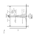
- FIG. 5 is a diagram of an example beam pattern 500 in accordance with the optimization techniques described herein.
- beam pattern 500 may include a steering direction with a beam width defined by a boundary steering vector on each side of the beam steering direction.
- beam pattern 500 may also include steep transition slopes that may help enable signal interference to be canceled or ignored during the beamforming process. For instance, as shown in FIG. 5 , the steep transition slopes create large portions of interference (of the 360-degree signal input) to be excluded from the extracted signal. In some implementations, nulling such large portions of interference may help maximize the gain of the target signal that is ultimately extracted from the sensor array inputs.
- the optimization object may be used to create an optimization solution.
- R(f, n) may represent a M ⁇ M matrix (with M representing a number of sensors), ⁇ (f, n, E, slop) may represent a function based on frequency, time, power of sensor input, and a slope constant, and W(f, n) H W(f, n) may represent white noise gain, and ⁇ may represent a raw vector with MM elements.
- I M is an identity matrix with dimension M (e.g., an identity matrix that is a M by M square matrix with ones on the main diagonal and zeros elsewhere.
- ⁇ (v) may represent a function and v is the first column and first raw of ⁇ without the offset to control both beam width and beam transition as specified herein (e.g., regardless of variable such as frequency and time).
- the optimization solution may include a modification of the optimization object to ensure that beam width and beam transition may be uniform across different frequency. Said another way, the optimization object may ensure a pre-specified beam width and beam transition, and the optimization solution may ensure that the pre-specified beam width and beam transition is consistent across different frequencies.
- a weighted vector W(f, n) is obtained. Output from the analysis filter bank is then filtered via the weighted vector and filtered outputs are expected to be the target signal in frequency domain at that time, which is input to Synthesis Filter-Band.
- Outputs of Sensor Weight Vector are optimized output in frequency domain at that time. Optimal means that they are target signal in bands of frequencies at that time.
- the outputs are inputs to Synthesis Filter-Bank. Synthesis Filter-Bank converts signals in the band of frequencies to a time-only signal via a known technology, for example, a DFT synthesis filter-bank.
- the output from the synthesis filter bank may be provided to another component of computing device 210 (or to another device altogether) to be interpreted, stored, and/or processed for other potential uses. For instance, if computing device 210 can interpret and implement audio commands from a user, the output from the synthesis filter bank may be a digital version of the audio command that is sent to an audio signal interpretation component of computing device 210 .
- FIG. 6 is a diagram of some of the components of computing device 210 .
- computing device 210 may include a sensor array, a beamforming system, and a signal interpretation system.
- computing device 210 may include additional and/or alternative components.
- the sensor array, beamforming system, and signal interpretation system may be implemented as circuitry, which may include hardware, software, and/or a combination thereof. The function of the beamforming system and signal interpretation system are described herein with reference to FIGS. 3, 4, and 7 .
- the sensor array includes four microphones that are arranged in a pattern—three microphones that are equidistance from one another along a circular perimeter and one microphone in the center.
- different types of sensors may be implemented, a different number of sensors may be implemented, and/or the sensors may be arranged in a different manner (e.g., in a line, on a sphere, on different surfaces, etc.).
- each of these variables e.g., sensor type, sensor number, sensor arrangement, etc.
- FIG. 7 is a diagram of an example process 700 for beamforming in accordance with the optimization techniques described herein.
- process 700 may be implemented by computing device 210 .
- Process 700 may be discussed below in terms of microphones and soundwaves. However, process 700 may also be applicable to other types of sensors and signals, such as an array of antennas capable of receiving radio waves.
- process 700 may include receiving an input from a signal array (block 710 ).
- computing device 210 may include an array of sensors (e.g., microphones, antennas, etc.) that may detect signals and inputs of those signals to a beamforming system of computing device 210 .
- Process 700 may also include determining a steering direction for a target signal from the inputs (block 720 ).
- a DOA analysis module may receive inputs from the Analysis Filter-Bank and may process the inputs in order to: 1) identify a recognizable signal from the inputs; 2) determine a DOA for signal; and 3) determine a steering direction based on the DOA.
- the DOA analysis module may analyze the inputs for signals in various frequency ranges and potential DOAs. In some implementations, multiple signals, corresponding to similar or different frequency ranges may be identified and processed.
- DOA may not be estimated.
- a space of 360 degrees is divided into several sub-spaces.
- the space may be divided into 9 sub-spaces, in which each has beam-width 40 degrees and steering directions are at the centers of each segment, respectively.
- Blocks 730 , 740 , and 750 may be repeated 9 times, and one from 9 outputs that are more voice-like or in terms of other standards, for example, maximum energy output, may be finally chosen.
- Many devices use this kind of applications.
- cell phones may have two microphones such that one is in front and another is in the back of the device.
- Steering direction may be specified as 0 degrees from the front of the device with a specified beam-width, such as 30 degrees.
- Process 700 may also include creating an optimization object and optimization solution for the target signal (block 730 ).
- a beamforming system may create an optimization object (or beamforming pattern) for the target signal, which may include the steering direction for the target signal, a beam width that is applied to the steering direction, and a steep transition slope that is applied to the beam width.
- the beamforming system may also create an optimization solution for the target signal, which may include taking the optimization object and standardizing the beam width and the transition slope, such that the same beam width and transition slope is applied to any target signal regardless of, for example, the frequency and/or reception time corresponding to the target signal.
- Process 700 may also include determining a sensor weight vector for the target signal (block 740 ).
- the beamforming system of computing device 210 may determine an appropriate weight vector for the inputs from the sensor array. As mentioned above regarding FIG. 3 , this may include assigning a weight to the input from each sensor, according to how well the sensor is positioned to receive the target signal.
- each sensor may depend on different factors, such as: 1) where each sensor is located relative the steering direction, 2) whether the sensor appears to be functioning properly, 3) whether the sensor is superior to other sensors in the array (e.g., more sensitive, 4) whether the sensor is better capable of receiving a particular type of signal (e.g., frequency), 5) whether the sensor corresponds to more advanced model or version, etc.), 7) whether the sensor appears to be receiving a greater portion of interference (e.g., the receiver is closer to another source of sound, device reverberation, etc.), etc.
- the weight associated with each sensor input may be based on the gain or input power with which the target signal was received.
- Process 700 may also include synthesizing an output for the target signal (block 750 ).
- computing device 210 may synthesize a unified output signal, representing the target signal, based on a combination of the input signals, optimization object and solutions for each input signal, and the weight assigned to each signal.
- synthesizing the target signal in this manner may maximize the level of quality (e.g., signal to noise ratio, overall gain, etc.) with which the target signal is extracted from the sensor array inputs.
- the synthesized output may be sent to a signal interpretation component (e.g., a component for recognizing, interpreting, and implementing audio commands from a user).
- FIG. 8 is a diagram of example components of a device 800 .
- Each of the devices illustrated in FIGS. 1A, 2, and 6 may include one or more devices 800 .
- Device 800 may include bus 810 , processor 820 , memory 830 , input component 840 , output component 850 , and communication interface 860 .
- device 800 may include additional, fewer, different, or differently arranged components.
- a component may be implemented by circuitry, which may include hardware circuitry, software logic, and/or some combination thereof.
- Bus 810 may include one or more communication paths that permit communication among the components of device 800 .
- Processor 820 may include a processor, microprocessor, or processing logic that may interpret and execute instructions.
- Memory 830 may include any type of dynamic storage device that may store information and instructions for execution by processor 820 , and/or any type of non-volatile storage device that may store information for use by processor 820 .
- Input component 840 may include a mechanism that permits an operator to input information to device 800 , such as a keyboard, a keypad, a button, a switch, etc.
- Output component 850 may include a mechanism that outputs information to the operator, such as a display, a speaker, one or more light emitting diodes (LEDs), etc.
- LEDs light emitting diodes
- Communication interface 860 may include any transceiver-like mechanism that enables device 800 to communicate with other devices and/or systems.
- communication interface 860 may include an Ethernet interface, an optical interface, a coaxial interface, or the like.
- Communication interface 860 may include a wireless communication device, such as an infrared (IR) receiver, a cellular radio, a Bluetooth radio, or the like.
- the wireless communication device may be coupled to an external device, such as a remote control, a wireless keyboard, a mobile telephone, etc.
- device 800 may include more than one communication interface 860 .
- device 800 may include an optical interface and an Ethernet interface.
- Device 800 may perform certain operations described above. Device 800 may perform these operations in response to processor 820 executing software instructions stored in a computer-readable medium, such as memory 830 .
- a computer-readable medium may be defined as a non-transitory memory device.
- a memory device may include space within a single physical memory device or spread across multiple physical memory devices.
- the software instructions may be read into memory 830 from another computer-readable medium or from another device.
- the software instructions stored in memory 830 may cause processor 820 to perform processes described herein.
- hardwired circuitry may be used in place of or in combination with software instructions to implement processes described herein. Thus, implementations described herein are not limited to any specific combination of hardware circuitry and software.
- logic may include hardware, such as an application-specific integrated circuit (ASIC) or a field-programmable gate array (FPGA), or a combination of hardware and software.
- ASIC application-specific integrated circuit
- FPGA field-programmable gate array
Landscapes
- Engineering & Computer Science (AREA)
- Health & Medical Sciences (AREA)
- Physics & Mathematics (AREA)
- Acoustics & Sound (AREA)
- Otolaryngology (AREA)
- Signal Processing (AREA)
- Human Computer Interaction (AREA)
- Audiology, Speech & Language Pathology (AREA)
- Multimedia (AREA)
- General Health & Medical Sciences (AREA)
- Computational Linguistics (AREA)
- Circuit For Audible Band Transducer (AREA)
- Measurement Of Velocity Or Position Using Acoustic Or Ultrasonic Waves (AREA)
Abstract
Description
A(f,δ)H W(f,n)=Δ
where A(f, δ) is a steering matrix consisting of column vectors of: a(f, δi) 1«i« MM (number of columns), δ is any steering direction angle or center angle, f is signal frequency, n is signal time, ( . . . )H is a complex transpose operation, W(f, n) is a column weight vector, and Δ is a column vector. In some implementations, the steering vectors used to define the other conditions, such as amplitude variations, may also be expressed by the steering direction matrix, which may be significant since amplitude variations may exist in different practical devices. As shown, transition parameters may be used to determine transition slopes for the signal.
J(f,n)=W(f,n)H R(f,n)W(f,n)+ε(f,n,E,slop)W(f,n)H W(f,n)
where W(f, n)H may represent a complex transpose operation (( . . . )H) applied to a column weight vector ([w1(f, n) w2(f, n) . . . wM(f, n)]H), R(f, n) may represent a M×M matrix (with M representing a number of sensors), and W(f, n)HW(f, n) may represent white noise gain. Additionally, ε(f, n, E, slop) may be expressed as:
ε(f,n,E,slop)=c(slop)*b(f)*E(n)
where c(slop) may represent a proportion of slop, b(f) may represent a function of frequency that equalizes the beam width for all frequencies (by, for example, setting b(f)=f2), and E(n) may represent a level of microphone input power at time n.
J(f,n)=W(f,n)H [R(f,n)+ε(f,n,E,slop)I M ]W(f,n)−2λH(A(f,δ)H W(f,n)−Δ)
where W(f, n)H may represent a complex transpose operation (( . . . )H) applied to a column weight vector ([w1(f, n) w2(f, n) . . . wM(f, n)]H, R(f, n) may represent a M×M matrix (with M representing a number of sensors), ε(f, n, E, slop) may represent a function based on frequency, time, power of sensor input, and a slope constant, and W(f, n)HW(f, n) may represent white noise gain, and λ may represent a raw vector with MM elements. IM is an identity matrix with dimension M (e.g., an identity matrix that is a M by M square matrix with ones on the main diagonal and zeros elsewhere. Taking the derivative of the foregoing expression with respect to W, may result in:
2R 1(f,n)W−2A(f,δ)λ=O M
where OM may be a column vector with all zeros as elements and R1(f, n)=R(f, n)+ε(f, n, E, slop)IM. Working from the foregoing derivative, W(f, n) may be expressed as: W(f, n)=R1 −1(f, n)A(f, n)λ, where λ=[A(f, δ)HR1 −1(f, n)A(f, δ)]−1Δ=Γ−1Δ. The expression: Γ=A(f, δ)HR1 −1(f, n)A(f, δ) may include an MM by MM matrix to which it may be useful to add a offset, as in:
Γ=A(f,δ)H R 1 −1(f,n)A(f,δ)+σ(v)
Claims (20)
Priority Applications (1)
| Application Number | Priority Date | Filing Date | Title |
|---|---|---|---|
| US15/384,598 US10015588B1 (en) | 2016-12-20 | 2016-12-20 | Beamforming optimization for receiving audio signals |
Applications Claiming Priority (1)
| Application Number | Priority Date | Filing Date | Title |
|---|---|---|---|
| US15/384,598 US10015588B1 (en) | 2016-12-20 | 2016-12-20 | Beamforming optimization for receiving audio signals |
Publications (2)
| Publication Number | Publication Date |
|---|---|
| US20180176679A1 US20180176679A1 (en) | 2018-06-21 |
| US10015588B1 true US10015588B1 (en) | 2018-07-03 |
Family
ID=62562183
Family Applications (1)
| Application Number | Title | Priority Date | Filing Date |
|---|---|---|---|
| US15/384,598 Active US10015588B1 (en) | 2016-12-20 | 2016-12-20 | Beamforming optimization for receiving audio signals |
Country Status (1)
| Country | Link |
|---|---|
| US (1) | US10015588B1 (en) |
Families Citing this family (12)
| Publication number | Priority date | Publication date | Assignee | Title |
|---|---|---|---|---|
| CN107071636B (en) * | 2016-12-29 | 2019-12-31 | 北京小鸟听听科技有限公司 | Dereverberation control method and device for equipment with microphone |
| KR102812754B1 (en) * | 2019-10-15 | 2025-05-23 | 삼성전자주식회사 | Communication device and data receiving method thereof |
| CN110827846B (en) * | 2019-11-14 | 2022-05-10 | 深圳市友杰智新科技有限公司 | Speech noise reduction method and device adopting weighted superposition synthesis beam |
| CN113393856B (en) * | 2020-03-11 | 2024-01-16 | 华为技术有限公司 | Sound pickup methods, devices and electronic equipment |
| IL273499A (en) * | 2020-03-22 | 2021-09-30 | Qualcomm Inc | Radio frequency sensing for control of a media system |
| CN115605953B (en) | 2020-05-08 | 2026-03-17 | 微软技术许可有限责任公司 | Systems and methods for data enhancement in multi-microphone signal processing |
| CN113571038B (en) * | 2021-07-14 | 2024-06-25 | 北京小米移动软件有限公司 | Voice dialogue method, device, electronic device and storage medium |
| CN113782046B (en) * | 2021-09-09 | 2024-09-17 | 清华大学 | Microphone array sound pickup method and system for long-distance speech recognition |
| US12242010B2 (en) | 2022-03-29 | 2025-03-04 | Halliburton Energy Services, Inc. | Hydrophone gain design for array noise tool |
| US12331631B2 (en) | 2022-03-29 | 2025-06-17 | Halliburton Energy Services, Inc. | Acoustic noise source localization based on cross-correlation functions across a hydrophone array |
| CN116962937A (en) * | 2022-04-14 | 2023-10-27 | 华为技术有限公司 | Wearable devices, sound pickup methods and devices |
| CN116301195B (en) * | 2023-05-16 | 2023-09-05 | 湖南工商大学 | Function beam optimization method and device |
Citations (3)
| Publication number | Priority date | Publication date | Assignee | Title |
|---|---|---|---|---|
| US20050195988A1 (en) * | 2004-03-02 | 2005-09-08 | Microsoft Corporation | System and method for beamforming using a microphone array |
| US20120093344A1 (en) * | 2009-04-09 | 2012-04-19 | Ntnu Technology Transfer As | Optimal modal beamformer for sensor arrays |
| US20170280235A1 (en) * | 2016-03-24 | 2017-09-28 | Intel Corporation | Creating an audio envelope based on angular information |
-
2016
- 2016-12-20 US US15/384,598 patent/US10015588B1/en active Active
Patent Citations (3)
| Publication number | Priority date | Publication date | Assignee | Title |
|---|---|---|---|---|
| US20050195988A1 (en) * | 2004-03-02 | 2005-09-08 | Microsoft Corporation | System and method for beamforming using a microphone array |
| US20120093344A1 (en) * | 2009-04-09 | 2012-04-19 | Ntnu Technology Transfer As | Optimal modal beamformer for sensor arrays |
| US20170280235A1 (en) * | 2016-03-24 | 2017-09-28 | Intel Corporation | Creating an audio envelope based on angular information |
Also Published As
| Publication number | Publication date |
|---|---|
| US20180176679A1 (en) | 2018-06-21 |
Similar Documents
| Publication | Publication Date | Title |
|---|---|---|
| US10015588B1 (en) | Beamforming optimization for receiving audio signals | |
| US12361935B2 (en) | Audio recognition method, method, apparatus for positioning target audio, and device | |
| US10327221B1 (en) | Super-resolution technique for time-of-arrival estimation | |
| CN107018470B (en) | A kind of voice recording method and system based on annular microphone array | |
| US7099821B2 (en) | Separation of target acoustic signals in a multi-transducer arrangement | |
| Salvati et al. | Incoherent frequency fusion for broadband steered response power algorithms in noisy environments | |
| US9521486B1 (en) | Frequency based beamforming | |
| CN107889001B (en) | Expandable microphone array and establishing method thereof | |
| RU2716022C1 (en) | Configuration of settings for beam formation for wireless device of radio transceiver | |
| Kiong et al. | Minimum variance distortionless response beamformer with enhanced nulling level control via dynamic mutated artificial immune system | |
| Rahaman | Least mean square (LMS) for smart antenna | |
| WO2021243634A1 (en) | Binaural beamforming microphone array | |
| EP4331126A1 (en) | Apparatus, system, and method for adaptive beamforming in wireless networks | |
| US9443531B2 (en) | Single MIC detection in beamformer and noise canceller for speech enhancement | |
| US9646629B2 (en) | Simplified beamformer and noise canceller for speech enhancement | |
| JP2022547493A (en) | Wind noise detection | |
| WO2020118290A1 (en) | System and method for acoustic localization of multiple sources using spatial pre-filtering | |
| Chai | Advanced techniques in adaptive beamforming for enhanced doa estimation | |
| Malla et al. | Design and analysis of direction of arrival using hybrid expectation-maximization and MUSIC for wireless communication | |
| Abohamra et al. | Direction of Arrival algorithms for user identification in cellular networks | |
| CN115866483A (en) | Beam forming method and device for audio signal | |
| CN117153180A (en) | Sound signal processing method, device, storage medium and electronic equipment | |
| CN108692718A (en) | Steady navigation anti-interference method based on blind wave beam and its system | |
| Chen et al. | Robust adaptive beamforming based on matched spectrum processing with little prior information | |
| Shang et al. | The analysis of interference suppression capability of mvdr algorithm based on microphone array |
Legal Events
| Date | Code | Title | Description |
|---|---|---|---|
| AS | Assignment |
Owner name: VERIZON PATENT AND LICENSING, INC., NEW JERSEY Free format text: ASSIGNMENT OF ASSIGNORS INTEREST;ASSIGNORS:LU, YOUHONG;KALLURI, RAVI;WALTERS, ANDREW;AND OTHERS;SIGNING DATES FROM 20161212 TO 20161216;REEL/FRAME:040689/0745 |
|
| STCF | Information on status: patent grant |
Free format text: PATENTED CASE |
|
| MAFP | Maintenance fee payment |
Free format text: PAYMENT OF MAINTENANCE FEE, 4TH YEAR, LARGE ENTITY (ORIGINAL EVENT CODE: M1551); ENTITY STATUS OF PATENT OWNER: LARGE ENTITY Year of fee payment: 4 |
|
| MAFP | Maintenance fee payment |
Free format text: PAYMENT OF MAINTENANCE FEE, 8TH YEAR, LARGE ENTITY (ORIGINAL EVENT CODE: M1552); ENTITY STATUS OF PATENT OWNER: LARGE ENTITY Year of fee payment: 8 |