US10012744B2 - Imaging device using a close proximity tag to configure a wireless local area network (LAN) transceiver - Google Patents
Imaging device using a close proximity tag to configure a wireless local area network (LAN) transceiver Download PDFInfo
- Publication number
- US10012744B2 US10012744B2 US15/018,362 US201615018362A US10012744B2 US 10012744 B2 US10012744 B2 US 10012744B2 US 201615018362 A US201615018362 A US 201615018362A US 10012744 B2 US10012744 B2 US 10012744B2
- Authority
- US
- United States
- Prior art keywords
- wap
- imaging device
- tag
- close proximity
- reader
- Prior art date
- Legal status (The legal status is an assumption and is not a legal conclusion. Google has not performed a legal analysis and makes no representation as to the accuracy of the status listed.)
- Expired - Fee Related
Links
- 238000003384 imaging method Methods 0.000 title claims abstract description 154
- 238000004891 communication Methods 0.000 claims abstract description 52
- 239000011159 matrix material Substances 0.000 claims abstract description 36
- 230000005855 radiation Effects 0.000 claims description 68
- 238000000034 method Methods 0.000 claims description 40
- 230000003287 optical effect Effects 0.000 claims description 12
- 230000005540 biological transmission Effects 0.000 claims description 7
- 238000004146 energy storage Methods 0.000 claims description 7
- 230000005670 electromagnetic radiation Effects 0.000 claims description 5
- 239000003990 capacitor Substances 0.000 claims description 4
- 238000005516 engineering process Methods 0.000 abstract description 15
- 230000006870 function Effects 0.000 description 21
- 230000033001 locomotion Effects 0.000 description 11
- 239000000463 material Substances 0.000 description 11
- 238000010586 diagram Methods 0.000 description 10
- 230000008569 process Effects 0.000 description 9
- 230000005674 electromagnetic induction Effects 0.000 description 5
- 230000006698 induction Effects 0.000 description 5
- XQPRBTXUXXVTKB-UHFFFAOYSA-M caesium iodide Chemical compound [I-].[Cs+] XQPRBTXUXXVTKB-UHFFFAOYSA-M 0.000 description 4
- 238000001514 detection method Methods 0.000 description 3
- 238000012545 processing Methods 0.000 description 3
- 230000004044 response Effects 0.000 description 3
- 238000003860 storage Methods 0.000 description 3
- 229920001621 AMOLED Polymers 0.000 description 2
- 238000003491 array Methods 0.000 description 2
- QWUZMTJBRUASOW-UHFFFAOYSA-N cadmium tellanylidenezinc Chemical compound [Zn].[Cd].[Te] QWUZMTJBRUASOW-UHFFFAOYSA-N 0.000 description 2
- 238000006243 chemical reaction Methods 0.000 description 2
- 238000013479 data entry Methods 0.000 description 2
- 238000013461 design Methods 0.000 description 2
- 238000002059 diagnostic imaging Methods 0.000 description 2
- 239000011521 glass Substances 0.000 description 2
- 230000007246 mechanism Effects 0.000 description 2
- YFDLHELOZYVNJE-UHFFFAOYSA-L mercury diiodide Chemical compound I[Hg]I YFDLHELOZYVNJE-UHFFFAOYSA-L 0.000 description 2
- 230000002093 peripheral effect Effects 0.000 description 2
- 238000010079 rubber tapping Methods 0.000 description 2
- 239000011669 selenium Substances 0.000 description 2
- 229910052688 Gadolinium Inorganic materials 0.000 description 1
- BUGBHKTXTAQXES-UHFFFAOYSA-N Selenium Chemical compound [Se] BUGBHKTXTAQXES-UHFFFAOYSA-N 0.000 description 1
- 239000000853 adhesive Substances 0.000 description 1
- 230000001070 adhesive effect Effects 0.000 description 1
- 238000013459 approach Methods 0.000 description 1
- 229910052790 beryllium Inorganic materials 0.000 description 1
- ATBAMAFKBVZNFJ-UHFFFAOYSA-N beryllium atom Chemical compound [Be] ATBAMAFKBVZNFJ-UHFFFAOYSA-N 0.000 description 1
- 230000033228 biological regulation Effects 0.000 description 1
- 229910052797 bismuth Inorganic materials 0.000 description 1
- JCXGWMGPZLAOME-UHFFFAOYSA-N bismuth atom Chemical compound [Bi] JCXGWMGPZLAOME-UHFFFAOYSA-N 0.000 description 1
- 230000004397 blinking Effects 0.000 description 1
- 229910052793 cadmium Inorganic materials 0.000 description 1
- BDOSMKKIYDKNTQ-UHFFFAOYSA-N cadmium atom Chemical compound [Cd] BDOSMKKIYDKNTQ-UHFFFAOYSA-N 0.000 description 1
- 230000001413 cellular effect Effects 0.000 description 1
- 238000010276 construction Methods 0.000 description 1
- 239000002826 coolant Substances 0.000 description 1
- 238000013481 data capture Methods 0.000 description 1
- 238000009826 distribution Methods 0.000 description 1
- 230000005672 electromagnetic field Effects 0.000 description 1
- UIWYJDYFSGRHKR-UHFFFAOYSA-N gadolinium atom Chemical compound [Gd] UIWYJDYFSGRHKR-UHFFFAOYSA-N 0.000 description 1
- XMBWDFGMSWQBCA-UHFFFAOYSA-N hydrogen iodide Chemical compound I XMBWDFGMSWQBCA-UHFFFAOYSA-N 0.000 description 1
- 238000007689 inspection Methods 0.000 description 1
- 230000010354 integration Effects 0.000 description 1
- 230000003993 interaction Effects 0.000 description 1
- RQQRAHKHDFPBMC-UHFFFAOYSA-L lead(ii) iodide Chemical compound I[Pb]I RQQRAHKHDFPBMC-UHFFFAOYSA-L 0.000 description 1
- 239000004973 liquid crystal related substance Substances 0.000 description 1
- 230000007774 longterm Effects 0.000 description 1
- 238000004519 manufacturing process Methods 0.000 description 1
- 238000013178 mathematical model Methods 0.000 description 1
- 229960003671 mercuric iodide Drugs 0.000 description 1
- 229910052751 metal Inorganic materials 0.000 description 1
- 239000002184 metal Substances 0.000 description 1
- 238000012986 modification Methods 0.000 description 1
- 230000004048 modification Effects 0.000 description 1
- 230000006855 networking Effects 0.000 description 1
- 230000008520 organization Effects 0.000 description 1
- 229910052702 rhenium Inorganic materials 0.000 description 1
- WUAPFZMCVAUBPE-UHFFFAOYSA-N rhenium atom Chemical compound [Re] WUAPFZMCVAUBPE-UHFFFAOYSA-N 0.000 description 1
- 229910052711 selenium Inorganic materials 0.000 description 1
- 238000001228 spectrum Methods 0.000 description 1
- 239000000758 substrate Substances 0.000 description 1
- 229910052716 thallium Inorganic materials 0.000 description 1
- BKVIYDNLLOSFOA-UHFFFAOYSA-N thallium Chemical compound [Tl] BKVIYDNLLOSFOA-UHFFFAOYSA-N 0.000 description 1
- 238000012546 transfer Methods 0.000 description 1
- 230000001960 triggered effect Effects 0.000 description 1
- KOECRLKKXSXCPB-UHFFFAOYSA-K triiodobismuthane Chemical compound I[Bi](I)I KOECRLKKXSXCPB-UHFFFAOYSA-K 0.000 description 1
- PBYZMCDFOULPGH-UHFFFAOYSA-N tungstate Chemical compound [O-][W]([O-])(=O)=O PBYZMCDFOULPGH-UHFFFAOYSA-N 0.000 description 1
- WFKWXMTUELFFGS-UHFFFAOYSA-N tungsten Chemical compound [W] WFKWXMTUELFFGS-UHFFFAOYSA-N 0.000 description 1
- 229910052721 tungsten Inorganic materials 0.000 description 1
- 239000010937 tungsten Substances 0.000 description 1
- 230000000007 visual effect Effects 0.000 description 1
- 238000004804 winding Methods 0.000 description 1
Images


Classifications
-
- G—PHYSICS
- G01—MEASURING; TESTING
- G01T—MEASUREMENT OF NUCLEAR OR X-RADIATION
- G01T7/00—Details of radiation-measuring instruments
-
- A—HUMAN NECESSITIES
- A61—MEDICAL OR VETERINARY SCIENCE; HYGIENE
- A61B—DIAGNOSIS; SURGERY; IDENTIFICATION
- A61B6/00—Apparatus or devices for radiation diagnosis; Apparatus or devices for radiation diagnosis combined with radiation therapy equipment
- A61B6/56—Details of data transmission or power supply, e.g. use of slip rings
- A61B6/563—Details of data transmission or power supply, e.g. use of slip rings involving image data transmission via a network
-
- G—PHYSICS
- G01—MEASURING; TESTING
- G01T—MEASUREMENT OF NUCLEAR OR X-RADIATION
- G01T1/00—Measuring X-radiation, gamma radiation, corpuscular radiation, or cosmic radiation
- G01T1/16—Measuring radiation intensity
- G01T1/17—Circuit arrangements not adapted to a particular type of detector
-
- G—PHYSICS
- G01—MEASURING; TESTING
- G01T—MEASUREMENT OF NUCLEAR OR X-RADIATION
- G01T1/00—Measuring X-radiation, gamma radiation, corpuscular radiation, or cosmic radiation
- G01T1/16—Measuring radiation intensity
- G01T1/20—Measuring radiation intensity with scintillation detectors
-
- H—ELECTRICITY
- H04—ELECTRIC COMMUNICATION TECHNIQUE
- H04W—WIRELESS COMMUNICATION NETWORKS
- H04W12/00—Security arrangements; Authentication; Protecting privacy or anonymity
- H04W12/04—Key management, e.g. using generic bootstrapping architecture [GBA]
-
- H—ELECTRICITY
- H04—ELECTRIC COMMUNICATION TECHNIQUE
- H04W—WIRELESS COMMUNICATION NETWORKS
- H04W12/00—Security arrangements; Authentication; Protecting privacy or anonymity
- H04W12/50—Secure pairing of devices
-
- H04W4/008—
-
- H—ELECTRICITY
- H04—ELECTRIC COMMUNICATION TECHNIQUE
- H04W—WIRELESS COMMUNICATION NETWORKS
- H04W4/00—Services specially adapted for wireless communication networks; Facilities therefor
- H04W4/80—Services using short range communication, e.g. near-field communication [NFC], radio-frequency identification [RFID] or low energy communication
-
- H04W76/021—
-
- H—ELECTRICITY
- H04—ELECTRIC COMMUNICATION TECHNIQUE
- H04W—WIRELESS COMMUNICATION NETWORKS
- H04W76/00—Connection management
- H04W76/10—Connection setup
- H04W76/11—Allocation or use of connection identifiers
-
- H—ELECTRICITY
- H04—ELECTRIC COMMUNICATION TECHNIQUE
- H04W—WIRELESS COMMUNICATION NETWORKS
- H04W24/00—Supervisory, monitoring or testing arrangements
- H04W24/02—Arrangements for optimising operational condition
-
- H—ELECTRICITY
- H04—ELECTRIC COMMUNICATION TECHNIQUE
- H04W—WIRELESS COMMUNICATION NETWORKS
- H04W84/00—Network topologies
- H04W84/02—Hierarchically pre-organised networks, e.g. paging networks, cellular networks, WLAN [Wireless Local Area Network] or WLL [Wireless Local Loop]
- H04W84/10—Small scale networks; Flat hierarchical networks
- H04W84/12—WLAN [Wireless Local Area Networks]
Definitions
- An x-ray system typically includes an x-ray tube and a detector.
- the power and signals for the x-ray tube can be provided by a tube generator.
- the x-ray tube emits radiation, such as x-rays, toward an object.
- the object is positioned between the x-ray tube and the detector.
- the radiation typically passes through the object and impinges on the detector.
- internal structures of the object cause spatial variances in the radiation received at the detector.
- the detector then generates data based on the detected radiation, and the system translates the radiation variances into an image, which may be used to evaluate the internal structure of the object, such as a patient in a medical imaging procedure or an inanimate object in an inspection scan.
- the radiation detector can include a conversion element that converts an incoming radiation beam into electrical signals, which can be used to generate data about the radiation beam, which in turn can be used to characterize an object being inspected (e.g., the patient or inanimate object).
- the conversion element includes a scintillator that converts a radiation beam into light, and a sensor that generates electrical signals in response to the light.
- the detector can also include processing circuitry that processes the electrical signals to generate data about the radiation beam.
- the radiation detector can be portable to allow images to be taken of the object in different positions or at different angles.
- the portable radiation detector can communicate with the rest of the imaging system, which can include the radiation source (e.g., x-ray tube) and image signal generator, via a wired or optical link (e.g., cable) or a wireless link (e.g., WiFi transceiver).
- the radiation detector may also be used or shared by various radiation sources (e.g., x-ray tube) or workstations (e.g., computer) in various locations (e.g., rooms). As such, the radiation detector may be reconfigured each time the detector is used with a different radiation source, workstation, or location.
- the technology (devices, systems, and methods) described herein provides solutions to configure an imaging device (e.g., radiation detector) to a workstation or a radiation source.
- An imaging device e.g., radiation detector
- a cable can be directly coupled via a cable to a workstation used to control an imaging system, process image data, or store image data.
- a cable can be problematic.
- the length of the cable can limit the range or the position that the imaging device can be used, the cable can get lost or misplaced, the cable can cause a tripping hazard, or the cable or cable connectors can wear out or become damaged.
- An imaging device that includes a wireless transceiver e.g., a wireless local area network [LAN] transceiver
- WAP wireless access point
- WiFi wireless protocol
- a service cable (or network cable) may still be needed to initially configure the wireless transceiver to communicate with the workstation, and the remaining data communication can occur between the wireless LAN transceiver and the WAP.
- the service cable may be eliminated entirely for configuring the wireless transceiver by using a close proximity tag.
- the imaging device includes an imaging matrix of pixel detector elements, a wireless LAN transceiver, a tag reader, and a controller.
- Each pixel detector element is configured to detect photon energy.
- the wireless LAN transceiver is configured to transmit imaging matrix data to at least one WAP.
- the tag reader is configured to read WAP configuration data from a close proximity tag (i.e., a first close proximity tag).
- the controller is coupled to the imaging matrix, the wireless LAN transceiver, and the tag reader.
- the controller is configured to initialize the wireless LAN transceiver for communication with a specified WAP using the WAP configuration data.
- the at least one WAP includes the specified WAP.
- the tag reader can include a near field communication (NFC) reader, a radio-frequency identification (RFID) reader, an optical reader, and a barcode reader
- the close proximity tag can include a NFC tag, a RFID microchip, a scannable image, or a barcode.
- the WAP configuration data can include a service set identifier (SSID), an Internet Protocol address (IP address), a passphrase, a country code, or a channel.
- the wireless LAN transceiver is configured to communicate using a WiFi, Institute of Electrical and Electronics Engineers (IEEE) 802.11 standard, Bluetooth, or IEEE 802.15 wireless communication standard.
- IEEE Institute of Electrical and Electronics Engineers
- the tag reader is configured to read a control function code from the close proximity tag or a second close proximity tag.
- the control function code can include an image device setting or a reset to default settings command.
- the imaging device is an radiation detector
- the imaging matrix is an radiation imaging matrix
- each pixel detector element is an radiation pixel detector element configured to detect radiation.
- the radiation imaging matrix can include a scintillator layer.
- the imaging device includes an energy storage component, such as a battery or a capacitor, configured to provide power to the imaging device.
- the imaging device can also include an indicator configured to provide an indication that the specified WAP is configured for communication with the imaging device.
- the indicator can include a speaker, a light, a light emitting diode (LED), or a display.
- the imaging device includes a motion sensor configured to detect motion of the imaging device and the detected motion is used to wake up at least a portion of circuitry of the imaging device.
- the motion sensor can include a motion detector, an accelerometer, a gyrometer, a gyroscope, or a rotation sensor.
- Another example provides a method of configuring an imaging device for communication with a WAP using a close proximity tag.
- the method includes the operation of retrieving WAP configuration data from a close proximity tag (i.e., a first close proximity tag) by a tag reader on an imaging device.
- the tag reader on the imaging device is placed with a detectable range (e.g., within one meter) of the close proximity tag.
- the next operation of the method can include configuring a wireless LAN transceiver to communicate with a WAP associated with the WAP configuration data.
- the method can further include communicating with the WAP via the wireless LAN transceiver.
- the communication includes transmission of image data from the imaging device.
- the imaging device can be a radiation detector that is configured to detect radiation and the image data can include an image generated from x-rays.
- the communication with the WAP via the wireless LAN transceiver can use at least one wireless communication standard, such as WiFi, IEEE 802.11 standard, Bluetooth, and IEEE 802.15 standard.
- the WAP configuration data includes a SSID, an IP address, a passphrase, a country code, or a channel.
- the tag reader can include a near field communication (NFC) reader, a radio-frequency identification (RFID) reader, an optical reader, and a barcode reader
- the close proximity tag can include a NFC tag, a RFID microchip, a scannable image, or a barcode.
- the method can further include generating an indication when the wireless LAN transceiver is configured to communicate with the WAP.
- the indicator can include a speaker, a light, a LED, or a display.
- the method can further include retrieving embedded control function code from the second close proximity tag by the tag reader on the imaging device.
- the tag reader on the imaging device is placed within a detectable range of the second close proximity tag.
- the method can further include performing a control function on the imaging device based on the embedded control function code, such as an imagge device setting or a reset to default settings command.
- the method can further include programming the close proximity tag with the WAP configuration data using a tag programmer.
- the tag programmer is placed within a detectable range of the close proximity tag.
- the next operation of the method can include positioning the close proximity tag within a communication range of the WAP.
- a radiation detector includes a radiation imaging matrix of radiation pixel detector elements, a WiFi transceiver, an NFC reader, and a controller. Each radiation pixel detector element is configured to detect radiation.
- the WiFi transceiver is configured to transmit radiation imaging matrix data to at least one WAP.
- the NFC reader is configured to read WAP configuration data from a NFC tag.
- the controller is coupled to the radiation imaging matrix, the WiFi transceiver, and the NFC reader, and the controller is configured to initialize the WiFi transceiver for communication with a specified WAP using the WAP configuration data.
- the at least one WAP includes the specified WAP.
- FIG. 1 illustrates a block diagram of an example x-ray tube.
- FIG. 2 illustrates a side view of layers in an example x-ray detector element of and x-ray imaging matrix in an x-ray detector.
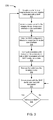
- FIG. 3 illustrates a flowchart for configuring an imaging device for communication with a WAP using a service cable.
- FIG. 4 illustrates a block diagram of an example imaging device with a tag reader.
- FIG. 5 illustrates a block diagram of an example x-ray detector with a near field communication (NFC) reader.
- NFC near field communication
- FIG. 6A illustrates a block diagram of an example x-ray system that includes an x-ray detector communicating with a workstation via a wireless access point (WAP) and the workstation includes an NFC tag and has a wired or optical connection to the x-ray tube.
- WAP wireless access point
- FIG. 6B illustrates a block diagram of an example x-ray system that includes an x-ray detector communicating with a workstation via a WAP and the workstation includes an NFC tag and has a wireless connection to the x-ray tube.
- FIG. 7 illustrates a block diagram of an example x-ray system that includes an x-ray detector communicating with a workstation that includes a barcode via a WAP.
- FIG. 8 illustrates a flowchart for configuring an imaging device for communication with a WAP using a close proximity tag.
- FIG. 9 illustrates a block diagram of an example x-ray detector that can be configured to multiple workstations where each workstation is associated with a WAP.
- FIG. 10 illustrates a flowchart for programming a close proximity tag with WAP configuration data.
- FIG. 11 illustrates a flowchart for performing a control function on an imaging device using a close proximity tag.
- FIG. 12 is flowchart illustrating an example of a method of configuring an imaging device for communication with a WAP using a close proximity tag.
- FIG. 13 illustrates a block diagram of an example imaging device with a wireless personal area networks (PAN) transceiver and a wireless local area network (LAN) transceiver.
- PAN personal area networks
- LAN wireless local area network
- Disclosed embodiments relate generally to an imaging device that includes a wireless LAN (e.g., WiFi) transceiver and a tag reader (e.g., NFC reader) and methods for configuring the wireless LAN transceiver and the imaging device using close proximity tags and the tag reader.
- Example embodiments illustrate mechanisms and methods to configure the wireless LAN transceiver and the imaging device without using a service cable.
- FIG. 1 is a block diagram of an example rotary or rotating anode type x-ray tube 100 with a rotatable disc-shaped anode 122 .
- the x-ray tube 100 includes a housing 102 and an x-ray insert 110 within the housing 102 .
- the housing 102 encloses the insert 110 .
- a coolant or air may fill the space or cavity between the housing 102 and the insert 110 .
- a cathode 112 and an anode assembly 120 are positioned within an evacuated enclosure, also referred to as the insert 110 .
- the anode assembly 120 includes the anode 122 , a bearing assembly 130 , and a rotor 128 mechanically coupled to the bearing assembly 130 .
- the anode 122 is spaced apart from and oppositely disposed to the cathode 112 .
- the anode 122 and cathode 112 are connected in an electrical circuit that allows for the application of a high voltage potential between the anode 122 and the cathode 112 .
- the cathode 112 includes an electron emitter 116 that is connected to an appropriate power source (not shown).
- the insert 110 is evacuated to create a vacuum.
- the insert 110 encloses the vacuum.
- an electrical current is passed through the electron emitter 116 of the cathode 112 to cause electrons “e” to be emitted from the cathode 112 by thermionic emission.
- the application of a high voltage differential between the anode 122 and the cathode 112 then causes the electrons “e” to accelerate from the cathode electron emitter toward a focal spot on a focal track 124 that is positioned on the anode 122 .
- the focal track 124 may be composed for example of tungsten (W) and rhenium (Re) or other materials having a high atomic (“high Z”) number. As the electrons “e” accelerate, they gain a substantial amount of kinetic energy, and upon striking the rotating focal track 124 some of this kinetic energy is converted into x-rays “x”.
- the focal track 124 is oriented so that emitted x-rays “x” are visible to an x-ray tube window 104 .
- the x-ray tube window 104 includes an x-ray transmissive material, such as beryllium (Be), so the x-rays “x” emitted from the focal track 124 pass through the x-ray tube window 104 in order to strike an intended object (not shown) and then the detector to produce an x-ray image (not shown).
- FIG. 1 illustrates a single window 104 on the housing 102 (e.g., with a glass insert that allows radiation to pass through the glass of the insert). In other examples, a separate window may be included on both the insert 110 (e.g., a metal insert) and the housing 102 , or a window may be included on just the insert 110 .
- a disc-shaped anode target is rotated at high speeds, typically using an induction motor that includes a rotor 128 and a stator 106 .
- the induction motor is an alternating current (AC) electric motor in which the electric current in the rotor 128 needed to produce torque is obtained by electromagnetic induction from a magnetic field of stator winding.
- the rotor 128 rotates a hub of the bearing assembly 130 that is mechanically coupled to the anode 122 , which rotates the anode 122 .
- the x-ray tube uses a stationary track.
- the radiation detector includes a matrix or array of pixel detector elements.
- the pixel detector elements e.g., x-ray detector element or detector element
- a detector element may include a photoconductor material which can convert x-ray photons directly to electrical charges (electron-hole pairs) in a direct detection scheme.
- Suitable photoconductor material include and are not limited to mercuric iodide (HgI 2 ), lead iodide (PbI 2 ), bismuth iodide (BiI 3 ), cadmium zinc telluride (CdZnTe), or amorphous selenium (a-Se).
- a detector element may comprise a scintillator material which converts x-ray photons to light and a photosensitive element coupled to the scintillator material to convert the light to electrical charges (i.e., indirect detection scheme), as illustrated in FIG. 2 .
- the x-ray imaging matrix 212 may include other layers, sections shown may include multiple layers (e.g., detector circuitry 426 includes multiple processing layers), or the layers may be in a different order.
- Suitable scintillator materials include and are not limited to gadolinium oxisulfide (Gd 2 O 2 S:Tb), cadmium tungstate (CdWO 4 ), bismuth germanate (Bi 4 Ge 3 O 12 or BGO), cesium iodide (CsI), or cesium iodide thallium (CsI:Tl)).
- Suitable photosensitive element may include a photodiode, a photogate, or phototransistors. Other circuitry for pixel detector elements may also be used.
- the x-ray tube and radiation detector can be components in an imaging system that are located in an x-ray room.
- a healthcare provider e.g., hospital
- a radiation detector e.g., wireless flat panel wireless portable x-ray detector
- Each x-ray source can have a workstation associated with the x-ray source and each workstation can be coupled to a wireless access point (WAP) associated with the workstation.
- WAP wireless access point
- the radiation detector can include a wireless local area network (LAN) transceiver (e.g., WiFi transceiver) that communicates with the WAP.
- LAN wireless local area network
- a wireless transceiver is a device that is configured to transmit or receive wireless signals via an air interface.
- a LAN is a computer network that interconnects computers within a limited area such as a residence, school, laboratory, or office building. Local refers to the range of the area network.
- the embodiments described can also apply to other area networks, such as wide area networks (WANs) and personal area networks (PANs).
- the WAN is a telecommunications network or computer network that extends over a large geographical distance
- PAN personal digital assistants.
- LAN refers to a LAN and smaller area networks, such as PANs.
- LAN can refer to a LAN and larger area networks, such as a WAN.
- a wireless LAN is a wireless computer network that links two or more devices using a wireless distribution method (e.g., spread-spectrum or orthogonal frequency-division multiplexing [OFDM] radio) within the LAN.
- Many WLANs are based on Institute of Electrical and Electronics Engineers (IEEE) 802.11 standards (e.g., 802.11ac, 802.11ad), which is commonly known to industry groups as WiFi (Wi-Fi).
- IEEE Institute of Electrical and Electronics Engineers
- 802.11ac 802.11ad
- WiFi Wi-Fi
- a WLAN may also use another technology besides WiFi.
- a wireless PAN is a PAN carried over wireless network technologies such as Bluetooth, Wireless Universal Serial Bus (USB), or ZigBee.
- Bluetooth is a wireless technology standard for exchanging data over short distances (e.g., using short-wavelength ultra-high frequency [UHF] radio waves in the industrial, scientific and medical [ISM] radio band from 2.4 to 2.485 gigahertz [GHz]).
- Wireless USB is a short-range, high-bandwidth wireless radio communication protocol which can increase the availability of general USB-based technologies.
- ZigBee is an IEEE 802.15.4-based specification for a suite of high-level communication protocols.
- a wireless WAN is a WAN carried over a wireless network using mobile telecommunication cellular network technologies such as such as the third generation partnership project (3GPP) long term evolution (LTE) (e.g., Release 11 or 12), High Speed Packet Access (HSPA), or IEEE 802.16 standard (e.g., 802.16e, 802.16m), which is commonly known to industry groups as WiMAX (Worldwide interoperability for Microwave Access).
- 3GPP third generation partnership project
- LTE long term evolution
- HSPA High Speed Packet Access
- IEEE 802.16 standard e.g., 802.16e, 802.16m
- WiMAX Worldwide interoperability for Microwave Access
- the WAP (or receptor) is a networking hardware device that allows wireless devices to connect to a wired network using a wireless protocol (e.g., WiFi).
- the WAP may be an external device associated with a workstation or integrated into a workstation (e.g., laptop computer).
- x-ray rooms are lined with a shielding material (e.g., lead) that blocks electromagnetic radiation, such as x-radiation radiation or x-ray electromagnetic radiation, from leaving the room and exposing those outside the room unnecessarily to the radiation.
- X-radiation is a form of electromagnetic radiation that has a wavelength ranging from 0.01 to 10 nanometers (nm), corresponding to frequencies in the range 30 petahertz to 30 exahertz (3 ⁇ 10 16 Hz to 3 ⁇ 10 19 Hz) and energies in the range 100 electronvolts (eV) to 100 kiloelectronvolts (keV).
- each workstation in an x-ray room may have its own WAP or a group of workstations in an x-ray room may have their own WAP.
- Each WAP can have a different configuration from other WAPs, which needs to be known or identified by the radiation detector (e.g., the portable radiation detector) before the radiation detector can be used with the workstation in communication with the WAP.
- a cable e.g., service cable or network cable
- a radiation detector e.g., panel or flat panel
- the workstation sends configuration information to the portable detector, as illustrated in the flowchart 300 shown in FIG. 3 .
- a cable can be coupled from a imaging device (e.g., radiation detector) to a workstation associated with a WAP 302 .
- a user accesses a control panel (e.g., web page) for the imaging device using a user interface (e.g., graphical user interface [GUI] or web browser) on a display of the workstation 304 .
- GUI graphical user interface
- a wireless LAN transceiver is configured to communicate with a WAP associated with the WAP configuration data 308 .
- the cable is removed from the imaging device 310 .
- the wireless LAN transceiver communicates with the WAP 312 , which can include imaging data, until another WAP is selected.
- the process 300 of using the cable 302 is repeated.
- the WAP configuration data can include information used to configure a wireless LAN transceiver for a specified WAP.
- the WAP configuration data can include a service set identifier (SSID), an Internet Protocol address (IP address), a passphrase, a country code, a channel, and other similar configuration data.
- WAPs Access points
- WAPs wireless network interface card
- NIC wireless network interface card
- BSS basic service set
- IP Internet Protocol
- a passphrase is a sequence of words, text, letters, numbers, or special characters used to control access to a network, computer system, program, or data.
- ASCII American Standard Code for Information Interchange
- the country code can be used to set the allowable channels (e.g., RF frequencies), allowed users, and maximum power levels within the allowed frequency ranges.
- WLAN standards e.g., WiFi
- a close proximity tag e.g., NFC tag
- the WAP configuration data can be embedded in the close proximity tag.
- the WAP configuration data on the close proximity tag can then be read by a tag reader (e.g., NFC reader) located on the imaging device, which is used to configure the WLAN transceiver.
- FIG. 4 illustrates an imaging device 200 that includes a housing 208 , an imaging matrix 210 of pixel detector elements, a wireless LAN transceiver 220 that allows wireless communication with a WAP, a tag reader 230 that reads a close proximity tag, and a controller 240 that controls the imaging device or coordinates communication between imaging device modules (e.g., wireless LAN transceiver and tag reader).
- the LAN transceiver includes multiple transceivers for different communication protocols (e.g., WPAN transceiver for Bluetooth and WLAN transceiver for WiFi).
- the wireless LAN transceiver 220 can include a single antenna or multiple antennas 224 .
- the tag reader 230 is configured to read or capture information on a close proximity tag when the tag reader is within a close distance, a detectable range, or close proximity to the close proximity tag. When the reader is farther than the close proximity distance or the detectable range from the tag, the tag reader is unable to read or capture information on the close proximity tag.
- the detectable range is less than 10 centimeters (cm). In another example, the detectable range is less than 1 m. In another example, the detectable range is less than 10 m.
- the close proximity tag can be placed in a convenient location in a room (e.g., an x-ray room). The close proximity tag may be included in a label with adhesive allowing the tag to be attached to the convenient location.
- “tapping” a tag refers to putting a device that includes the tag reader in close proximity (e.g., the detectable range) to the close proximity tag.
- the close proximity tag is an unpowered tag that does not include a power source to power the tag.
- the automatic identification and data capture (AIDC) technology includes the close proximity tag, tag reader, and tag programmer.
- AIDC includes the devices, systems, and methods of automatically identifying objects, collecting data about them, and entering that data directly into computer systems (e.g., without human involvement in the data entry).
- the close proximity tag can include a near field communication (NFC) tag that can be read by a NFC reader, a radio-frequency identification (RFID) microchip that can be read by a RFID reader, a scannable image that includes information that can be read by an optical reader, a barcode that can be read by a barcode reader, or a magnetic stripe that can be read by a magnetic reading head.
- NFC near field communication
- RFID radio-frequency identification
- NFC is a set of close-range wireless communication protocols for very short-range radio transmissions.
- NFC enable two electronic devices (e.g., a portable device or a tag) to establish communication by bringing them within a detectable range (i.e., close proximity) of each other, such as 10 cm (approximately 4 inches [in]).
- NFC employs electromagnetic induction between two loop antenna when NFC devices (e.g., a NFC reader and a NFC tag) exchange information.
- NFC can operate within a globally available unlicensed radio frequency ISM band of approximately 13.56 megahertz (MHz) on an International Organization for Standardization (ISO) and the International Electrotechnical Commission (IEC) (ISO/IEC) 18000-3 air interface at rates ranging from 106 to 424 kilobits per second (kbit/s).
- NFC devices e.g., NFC reader
- NFC card emulation mode enables NFC-enabled devices, such as smartphones, to act like smart cards, which allows users to perform transactions such as payment or ticketing.
- NFC reader/writer mode enables NFC-enabled devices to read information stored on inexpensive NFC tags embedded in labels or smart posters.
- NFC peer-to-peer mode enables two NFC-enabled devices to communicate with each other to exchange information in an adhoc fashion.
- the WAP configuration data can be programmed or written onto the NFC tag.
- Programming of the NFC tag can be performed by a device, such as a smart phone, that includes a NFC writer and a NFC programming application.
- the NFC tag can be read by a NFC reader.
- An NFC module may integrate the NFC reader and NFC writer functions.
- An NFC tag is a passive device, which operates without its own power supply and is reliant on an active device (e.g., NFC reader or NFC writer) to come into range before the NFC tag is activated.
- the NFC tag can include an induction coil and a tiny microchip (e.g., non-volatile random-access memory [NVRAM] or flash memory) that can electrically store and recall information.
- NVRAM non-volatile random-access memory
- RFID is a wireless use of electromagnetic fields to transfer data, which can be used for automatically identifying and tracking tags attached to objects.
- the RFID tag or microchip can include electronically stored information. Some tags can be powered by electromagnetic induction from magnetic fields produced near the RFID reader.
- the RFID tag includes an induction coil and a microchip. While NFC and RFID technologies have some similarities, RFID waves can have longer ranges (e.g., up to 100 m) than the NFC range (e.g., up to 20 cm) and the RFID tags may be larger, bulker, and more expensive than NFC tags (i.e., NFC tags may be smaller, thinner, and cheaper than the RFID tags).
- the RFID reader may consume more power than the NFC reader to induce sufficient current in the induction coils of the tag.
- NFC technology allows two-way communication, while RFID may only provide one-way reading or programming technology. In a configuration, NFC technology is an extension of RFID technology.
- Barcodes can be printed on labels or tags (e.g., paper) using a barcode printer.
- a barcode reader (or barcode scanner) is an electronic device that can read and output printed barcodes to a computer.
- the barcode reader includes a light source (e.g., laser), a lens, and a light sensor translating optical impulses from the barcode into an electrical signal or digital code.
- a light source e.g., laser
- the barcode reader includes a light source (e.g., laser), a lens, and a light sensor translating optical impulses from the barcode into an electrical signal or digital code.
- the controller 240 is a circuit that interfaces with various modules (e.g., wireless LAN transceiver 220 and tag reader 230 ) of the imaging device and other peripheral devices and can manage the operation of the imaging device.
- the processor can include a microprocessor, a field-programmable gate array (FPGA), or a state machine.
- the microprocessor is a computer processor that incorporates the functions of a central processing unit (CPU) with instruction code on a single IC.
- the FPGA is an integrated circuit (IC) designed to be configured by a customer or a designer after manufacturing.
- the state machine corresponds to a mathematical model of computation used to design sequential logic circuits, which uses one of a finite number of states in operation.
- the controller 240 is integrated with imaging matrix 210 , the wireless LAN transceiver 220 , or tag reader 230 .
- the controller function is provided by a combination of the imaging matrix, the wireless LAN transceiver, and tag reader.
- the imaging device 200 includes an indicator 250 that alerts or notifies a user that the WLAN transceiver has been configured with the WAP configuration data.
- the indicator can be coupled to the controller 240 , the tag reader 230 , or the wireless LAN transceiver 220 . Because the wireless LAN transceiver is automatically configured with the WAP configuration data using the close proximity tag, a user may not know if the wireless LAN transceiver is configured with the new WAP configuration data (e.g., that the tag reader was close enough to read the tag) or still has the old WAP configuration data prior to capturing imaging data.
- the workstation can display an indication or imaging device identifier (ID) showing that the imaging device is configured to communicate with the workstation, such as a pop up window or blinking screen.
- the imaging device includes an indicator, such as a speaker, a light, a light emitting diode (LED), or a display (e.g., liquid crystal display [LCD], organic light-emitting diode [OLED] display, or active-matrix OLED [AMOLED] display).
- LCD liquid crystal display
- OLED organic light-emitting diode
- AMOLED active-matrix OLED
- a speaker may produce a specified sound, a specified color LED illuminates, a specified sequence of LEDs illuminates, or a display displays the configured WAP or some other status or indicator indicating that the wireless LAN transceiver is configured with the new WAP configuration data.
- the speaker may produce a different sound if the tag reader attempts to read a close proximity tag and is unable to extract the WAP configuration data or is unable to configure the wireless LAN transceiver with the new WAP configuration data.
- the LED may illuminate a different color or other visual indicator if the tag reader attempts to read a close proximity tag and is unable to extract the WAP configuration data or is unable to configure the wireless LAN transceiver with the new WAP configuration data.
- the indicator can provide a quick notification to a user of the status of the wireless LAN transceiver's configuration.
- the imaging device 200 includes energy storage 260 that provides electrical power to the components and circuitry of the imaging device.
- the energy storage device can include a battery (e.g., rechargeable battery) or capacitor (e.g., super capacitor).
- the energy storage device can be charged via a cable, docketing station or contacts, or via electromagnetic induction.
- the imaging device 200 can include a motion sensor and a timer.
- the operations of tag reader e.g., reading or scanning
- a tag reader may consume unnecessary energy (e.g., drain on the battery) even when the tag reader is not in use, such as searching for a close proximity tag.
- the imaging device is being moved to a close proximity tag when a tag reader is needed to read the WAP configuration data from the tag, so motion of the imaging device can be associated with a tag reader being powered on.
- a motion sensor can reduce the energy expenditure of the imaging device by having the tag reader (or other devices or transmitting devices with minimal use) being put into sleep mode after a specified time without movement of the imaging device (as determined by a timer).
- the motion sensor can include an accelerometer, a gyrometer, a gyroscope, a magnetometer, a barometer, a rotation sensor, or a combination of these sensors.
- the tag reader may also be powered on and off with separate power switch (e.g., on/off switch) on the housing of the imaging device when the tag reader is not in use or not needed, or the tag reader can be powered on and off with a power switch also used for the imaging device.
- separate power switch e.g., on/off switch
- the imaging device 200 (or panel) illustrated in FIG. 4 can eliminate the need for a network service or a cable to configure the imaging device for sharing, thus making the act of sharing imaging devices (e.g., wireless portable detectors) relatively easy.
- the imaging device can remove the need for user interaction with the workstation directly in configuring the wireless LAN transceiver and reduce the errors associated with human data entry.
- FIG. 5 illustrates an imaging device or x-ray detector 202 (or x-ray panel), which can be used for medical imaging.
- X-ray detector 202 includes a housing 208 , an x-ray imaging matrix 212 of x-ray pixel detector elements, a WiFi transceiver 222 that allows wireless communication with a WAP, a NFC reader 232 that reads a NFC tag, and a controller 240 that controls the x-ray detector or coordinates communication between x-ray detector modules (e.g., WiFi transceiver and NFC reader).
- the x-ray imaging matrix 212 ( FIG. 2 ) includes a scintillator layer.
- the WiFi transceiver 222 includes at least one antenna 224 .
- the x-ray detector 202 may also include an indicator 250 or a battery 262 .
- FIGS. 6A and 6B illustrate the x-ray detector 202 scanning an NFC tag 270 associated with a workstation 280 or 282 , which can be used to configure a WiFi transceiver ( 222 in FIG. 5 ) of the x-ray detector with the WAP 284 or 286 of the workstation.
- the NFC tag is located within 10 m of the workstation.
- the WiFi transceiver can communicate with the workstation, a tube generator 292 , or a x-ray tube 290 via the WAP.
- the WAP 284 or 286 may include a single antenna or multiple antennas.
- the workstation 280 or 282 can also be used to capture and collect image data.
- FIG. 6A shows a wired or optical link or connection between the workstation 280 and the tube generator and the x-ray tube.
- FIG. 6B shows a wireless link between the workstation 282 , the tube generator and the x-ray tube, and the x-ray detector 202 .
- the tube generator 292 or the x-ray tube 290 may include a wireless LAN transceiver (e.g., WiFi transceiver) with at least one antenna 296 .
- the x-ray detector 202 may communicate to the tube generator and the x-ray tube directly or via the workstation 282 .
- FIG. 7 illustrates the x-ray detector 204 with a barcode reader 234 , as the tag reader, scanning a QR code (i.e., 2D barcode 278 ), as the close proximity tag, which is associated with the workstation 280 .
- the barcode reader and barcode can be used to configure a WiFi transceiver 222 of the x-ray detector with the WAP 284 of the workstation.
- various technologies can be used for the tag reader, the close proximity tag, and the wireless LAN transceiver.
- FIG. 8 illustrates a flowchart 320 for configuring an imaging device for communication with a WAP using a close proximity tag.
- the imaging device that includes a tag reader can be positioned a detectable range of a close proximity tag associated with a WAP 322 .
- the tag reader can read the WAP configuration data from the close proximity tag 324 .
- the wireless LAN transceiver can be configured to communicate with a WAP associated with the WAP configuration data 326 .
- the imaging device may reboot as part of the reconfiguration of the wireless LAN transceiver.
- the user or imaging device can verify that the wireless LAN transceiver is reconfigured with the new WAP configuration data 328 .
- the imaging device can generate an indication (e.g., audible sound, light emission, or display readout) that the wireless LAN transceiver is not configured with the new data.
- the user can reposition the imaging device closer or in a different position to the close proximity tag 322 , or the tag reader can rescan or reread the close proximity tag 324 until the wireless LAN transceiver is reconfigured or a timeout error or flag is generated, which may require further diagnostics by a user or technician.
- the imaging device can generate an indication (e.g., sound, light, or display) that the wireless LAN transceiver is configured properly 330 . Then the wireless LAN transceiver can communicate with the WAP 332 until a new WAP is selected 334 .
- the imaging device can be moved to another close proximity tag 322 and the process repeats.
- FIG. 9 illustrates an implementation of the configuration of workstations 282 A-C and WAPs using NFC tags 270 A-C.
- the diagram shown in FIG. 9 illustrates three x-ray rooms 402 A-C where each x-ray room includes a x-ray tube 290 A-C, a tube generator 292 A-C, and a workstation 282 A-C.
- the x-ray detector 202 may be used with any of the x-ray systems (e.g., x-ray tubes 290 A-C and tube generators 292 A-C) in the x-ray rooms.
- Each x-ray room may include walls 404 A-C and a door 406 A-C that are lined with a shielding material (e.g., lead) that blocks electromagnetic radiation, such as x-rays and RF signals, so the WAP for each x-ray system may be located within the room.
- a shielding material e.g., lead
- Each NFC tag 270 A-C includes the WAP configuration data for the WAP associated with the workstation 282 A-C.
- the close proximity tags 344 can be programmed with a tag programmer 342 (e.g., NFC writer) or a tag printer (e.g., barcode printer), as illustrated in FIG. 10 .
- the tag programmer 342 can program the close proximity tag with the WAP configuration data 348 . Then, the close proximity tag can be placed near the WAP (or a convenient or conspicuous place near the workstation associated with the WAP) 350 .
- the close proximity tags 344 can also be used to quickly perform a control function, such as resetting the image device to default settings (or factory settings) or changing a setting or group of settings on the image device.
- the tag programmer 342 can program the close proximity tag with the control function code 354 . Then, the close proximity tag can be placed in an accessible location 356 .
- the flowchart shown in FIG. 12 illustrates a method 500 of configuring an imaging device for communication with a WAP using a close proximity tag.
- the method may be executed as instructions on a machine or computer circuitry, where the instructions are included on at least one computer readable medium or at least one non-transitory machine readable storage medium.
- the method includes the step of retrieving WAP configuration data from a close proximity tag by a tag reader on an imaging device, wherein the tag reader on the imaging device is placed within a detectable range of the close proximity tag, as in step 510 .
- the next step of the method includes configuring a wireless LAN transceiver to communicate with a WAP associated with the WAP configuration data, as in step 520 .
- FIG. 13 illustrates an imaging device 206 that can configure the wireless LAN transceiver 220 (e.g., configured for WiFi) for wireless communication with a WAP using a wireless PAN transceiver 226 (e.g., configured for Bluetooth).
- the imaging device 206 includes a housing 208 , an imaging matrix 210 of pixel detector elements, a wireless LAN transceiver 220 that allows wireless communication with the WAP, a wireless PAN transceiver 226 that that allows wireless communication with a PAN WAP (not shown) or a corresponding wireless PAN (not shown; e.g., in a workstation), and a controller 240 that controls the imaging device or coordinates communication between imaging device modules (e.g., wireless LAN transceiver and wireless PAN transceiver).
- the wireless PAN transceiver 226 includes at least one antenna 228 .
- the imaging device 206 may also include an indicator 250 or energy storage 260 .
- a wireless PAN transceiver 226 can have a short effective transmission range (e.g., less than 10 m) similar to a tag reader. Thus, the wireless PAN transceiver may perform a similar function to a tag reader as previously discussed.
- the wireless PAN transceiver of the imaging device can be paired with the corresponding wireless PAN or the PAN WAP associated with each workstation or WAP (e.g., in each room). Pairing is a process that allows two devices (e.g., wireless PAN transceivers) to establish a communication link. Conventionally, the pairing process is triggered by either device making specific request to establish a link and a relationship is established by creating a shared secret known as a link key.
- a user may be involved in providing a pairing response or acknowledgment.
- the distance between workstations or electromagnetic shielding between workstations e.g., x-ray rooms
- the distance between workstations or electromagnetic shielding between workstations may only allow one corresponding wireless PAN or one PAN WAP to communicate with the wireless PAN transceiver of the imaging device at a time.
- the WAP configuration data i.e., LAN WAP configuration data
- a component e.g., memory
- the corresponding wireless PAN or the PAN WAP can send the LAN WAP configuration data to the wireless PAN transceiver.
- the imaging device 206 can configured the wireless LAN transceiver 220 for wireless communication with the WAP associated with the workstation.
- the imaging device configures the wireless LAN transceiver for wireless communication with the WAP associated with the other workstation.
- the technology (devices, systems, and methods) described herein can provide an efficient mechanism for configuring a wireless LAN transceiver of an imagining device for wireless communication with a WAP without a physical connection (e.g., wired or optical) to the workstation using a cable and without running a specific configuration application or program.
- Eliminating the cable for configuring the wireless LAN transceiver can reduce or eliminate the issues associated with cables, such as the length of the cable limiting the range or the position that the imaging device can be used, the cable can get lost or misplaced, the cable can cause a tripping hazard, or the cable or cable connectors can get damaged to repeatability of use.
- Circuitry can include hardware, firmware, program code, executable code, computer instructions, and/or software.
- a non-transitory computer readable storage medium can be a computer readable storage medium that does not include a signal.
- modules may be implemented as a hardware circuit comprising custom very-large-scale integration (VLSI) circuits or gate arrays, including but not limited to logic chips, transistors, or other components.
- VLSI very-large-scale integration
- a module may also be implemented in programmable hardware devices, including but not limited to field programmable gate arrays (FPGA), programmable array logic, programmable logic devices or similar devices.
- FPGA field programmable gate arrays
Landscapes
- Engineering & Computer Science (AREA)
- Health & Medical Sciences (AREA)
- Life Sciences & Earth Sciences (AREA)
- Computer Networks & Wireless Communication (AREA)
- Signal Processing (AREA)
- Physics & Mathematics (AREA)
- High Energy & Nuclear Physics (AREA)
- Molecular Biology (AREA)
- General Physics & Mathematics (AREA)
- Spectroscopy & Molecular Physics (AREA)
- Medical Informatics (AREA)
- Computer Security & Cryptography (AREA)
- Biomedical Technology (AREA)
- Nuclear Medicine, Radiotherapy & Molecular Imaging (AREA)
- Optics & Photonics (AREA)
- Pathology (AREA)
- Radiology & Medical Imaging (AREA)
- Biophysics (AREA)
- Heart & Thoracic Surgery (AREA)
- Surgery (AREA)
- Animal Behavior & Ethology (AREA)
- General Health & Medical Sciences (AREA)
- Public Health (AREA)
- Veterinary Medicine (AREA)
- Measurement Of Radiation (AREA)
Abstract
Description
Claims (18)
Priority Applications (2)
| Application Number | Priority Date | Filing Date | Title |
|---|---|---|---|
| US15/018,362 US10012744B2 (en) | 2016-02-08 | 2016-02-08 | Imaging device using a close proximity tag to configure a wireless local area network (LAN) transceiver |
| PCT/US2017/017043 WO2017139397A1 (en) | 2016-02-08 | 2017-02-08 | Imaging device using a close proximity tag to configure a wireless local area network (lan) transceiver |
Applications Claiming Priority (1)
| Application Number | Priority Date | Filing Date | Title |
|---|---|---|---|
| US15/018,362 US10012744B2 (en) | 2016-02-08 | 2016-02-08 | Imaging device using a close proximity tag to configure a wireless local area network (LAN) transceiver |
Publications (2)
| Publication Number | Publication Date |
|---|---|
| US20170227660A1 US20170227660A1 (en) | 2017-08-10 |
| US10012744B2 true US10012744B2 (en) | 2018-07-03 |
Family
ID=58185620
Family Applications (1)
| Application Number | Title | Priority Date | Filing Date |
|---|---|---|---|
| US15/018,362 Expired - Fee Related US10012744B2 (en) | 2016-02-08 | 2016-02-08 | Imaging device using a close proximity tag to configure a wireless local area network (LAN) transceiver |
Country Status (2)
| Country | Link |
|---|---|
| US (1) | US10012744B2 (en) |
| WO (1) | WO2017139397A1 (en) |
Families Citing this family (9)
| Publication number | Priority date | Publication date | Assignee | Title |
|---|---|---|---|---|
| CN107947966B (en) * | 2017-11-07 | 2020-10-02 | 深圳市信锐网科技术有限公司 | Configuration management system and configuration management method |
| KR102557945B1 (en) | 2017-12-01 | 2023-07-21 | 삼성전자주식회사 | X-ray detector and control method for the same |
| FR3075180B1 (en) * | 2017-12-14 | 2020-01-03 | Trixell | PORTABLE DIGITAL RADIOLOGICAL CASSETTE |
| US11026646B2 (en) * | 2018-02-07 | 2021-06-08 | Illinois Tool Works Inc. | Systems and methods for digital X-ray imaging |
| EP3734377A1 (en) * | 2019-05-02 | 2020-11-04 | ABB Schweiz AG | Method for configuring automation apparatus, automation apparatus, and reader apparatus |
| JP7363317B2 (en) * | 2019-05-10 | 2023-10-18 | コニカミノルタ株式会社 | Radiographic imaging equipment, electronic equipment, wireless communication systems and programs |
| US11684334B2 (en) * | 2019-08-27 | 2023-06-27 | GE Precision Healthcare LLC | Methods and systems for protocol management |
| FR3113217B1 (en) * | 2020-07-30 | 2022-10-28 | Oledcomm | Isolation device integrated in wireless optical communication equipment |
| US20230421990A1 (en) * | 2022-06-25 | 2023-12-28 | Lenovo (Singapore) Pte. Ltd | Automated Device Control Session |
Citations (2)
| Publication number | Priority date | Publication date | Assignee | Title |
|---|---|---|---|---|
| US20120057673A1 (en) * | 2010-09-07 | 2012-03-08 | William Eugene Campbell | Multi-Resolution X-Ray Image Capture |
| US8381270B1 (en) * | 2011-09-14 | 2013-02-19 | Google Inc. | Network configuration and authorization |
Family Cites Families (5)
| Publication number | Priority date | Publication date | Assignee | Title |
|---|---|---|---|---|
| JP5680935B2 (en) * | 2009-11-13 | 2015-03-04 | キヤノン株式会社 | Radiation imaging system, control method and program for radiation imaging system |
| JP5511583B2 (en) * | 2010-08-17 | 2014-06-04 | キヤノン株式会社 | Wireless communication apparatus, X-ray sensor, and wireless communication system |
| EP2624741B1 (en) * | 2010-10-07 | 2017-09-20 | Trophy | Association of wireless detector with an imaging apparatus |
| JP5884630B2 (en) * | 2012-05-14 | 2016-03-15 | コニカミノルタ株式会社 | Radiation imaging system |
| JP6164876B2 (en) * | 2013-03-06 | 2017-07-19 | キヤノン株式会社 | X-ray imaging system |
-
2016
- 2016-02-08 US US15/018,362 patent/US10012744B2/en not_active Expired - Fee Related
-
2017
- 2017-02-08 WO PCT/US2017/017043 patent/WO2017139397A1/en active Application Filing
Patent Citations (2)
| Publication number | Priority date | Publication date | Assignee | Title |
|---|---|---|---|---|
| US20120057673A1 (en) * | 2010-09-07 | 2012-03-08 | William Eugene Campbell | Multi-Resolution X-Ray Image Capture |
| US8381270B1 (en) * | 2011-09-14 | 2013-02-19 | Google Inc. | Network configuration and authorization |
Non-Patent Citations (3)
| Title |
|---|
| Chandler, Nathan "What's an NFC tag?" webpage <http://electronics.howstuffworks.com/nfc-tag.htm>, accessed Feb. 5, 2016, published on Mar. 14, 2012, HowStuffWorks.com. |
| IHaveAnEvo1 "How to Set Up NFC Tags," multimedia webpage https://www.youtube.com/watch?v=ZUFMLpJUT70, accessed Feb. 5, 2016, published on Jun. 14, 2013. |
| Pinola, Melanie "What Is NFC and How Can I Use It?," webpage http://lifehacker.com/5943006/what-is-nfc-and-how-can-i-use-it, accessed Feb. 5, 2016, published on Sep. 13, 2012. |
Also Published As
| Publication number | Publication date |
|---|---|
| WO2017139397A1 (en) | 2017-08-17 |
| US20170227660A1 (en) | 2017-08-10 |
Similar Documents
| Publication | Publication Date | Title |
|---|---|---|
| US10012744B2 (en) | Imaging device using a close proximity tag to configure a wireless local area network (LAN) transceiver | |
| JP6367149B2 (en) | Radiography apparatus and electronic cassette | |
| US9661728B2 (en) | Radiographic image photographing system | |
| CN100569182C (en) | Radiation image obtains equipment and radiation image obtains system | |
| CN107257979B (en) | Method and apparatus for energy harvesting from proximity coupling devices | |
| US20080049901A1 (en) | Radiography System and Computer Radiography Program | |
| JP2016184923A (en) | Terminal configurable for use within unknown regulatory domain | |
| CN103479371A (en) | X-ray imaging system, information processing apparatus, and control method thereof | |
| JP2006263339A (en) | Image obtaining apparatus and image obtaining system | |
| JPWO2006101230A1 (en) | Radiographic image acquisition system, cassette, console, radiographic image communication system and program | |
| JPWO2006101233A1 (en) | Radiation imaging system, console, program executed on console | |
| US20180220988A1 (en) | X-ray detector | |
| KR20160024426A (en) | Method of Controlling of Transmission Power and Device therefor | |
| KR20190099184A (en) | X-ray detector, mobile device, workstation, x-ray imaging apparatus and method for pairing of x-ray detector with workstation | |
| EP3492017B1 (en) | X-ray detector and method for controlling the same | |
| US20190166585A1 (en) | Dynamic allocation of multiple wireless interfaces in an imaging device | |
| US10812963B2 (en) | Augmented onboarding of internet-of-things devices | |
| JP5298865B2 (en) | Radiation image generation system | |
| US20230035400A1 (en) | Conditional cell change for emission mitigation | |
| US11246030B2 (en) | Control method for controlling wireless device by means of service set identifier | |
| JP2010057708A (en) | Radiological imaging system | |
| JP2010249572A (en) | System and device for generating radiation image | |
| CN108303724B (en) | Radioactive source detection device | |
| JP2010197679A (en) | Radiation image acquiring system, and radiation image detecting cassette | |
| US20230224867A1 (en) | Technologies for inter-user equipment coordination |
Legal Events
| Date | Code | Title | Description |
|---|---|---|---|
| AS | Assignment |
Owner name: VARIAN MEDICAL SYSTEMS, INC., CALIFORNIA Free format text: ASSIGNMENT OF ASSIGNORS INTEREST;ASSIGNORS:ZHANG, YAO;BATTS, MARK D;GRAY, KEITH DOUGLAS;SIGNING DATES FROM 20160208 TO 20160209;REEL/FRAME:037718/0824 |
|
| AS | Assignment |
Owner name: VAREX IMAGING CORPORATION, UTAH Free format text: ASSIGNMENT OF ASSIGNORS INTEREST;ASSIGNOR:VARIAN MEDICAL SYSTEMS, INC.;REEL/FRAME:041125/0098 Effective date: 20170125 |
|
| AS | Assignment |
Owner name: VAREX IMAGING CORPORATION, UTAH Free format text: CORRECTIVE ASSIGNMENT TO CORRECT THE ASSIGNEE ADDRESS PREVIOUSLY RECORDED ON REEL 041125 FRAME 0098. ASSIGNOR(S) HEREBY CONFIRMS THE ASSIGNMENT;ASSIGNOR:VARIAN MEDICAL SYSTEMS, INC.;REEL/FRAME:041608/0102 Effective date: 20170125 |
|
| STCF | Information on status: patent grant |
Free format text: PATENTED CASE |
|
| AS | Assignment |
Owner name: BANK OF AMERICA, N.A., AS AGENT, CALIFORNIA Free format text: SECURITY INTEREST;ASSIGNOR:VAREX IMAGING CORPORATION;REEL/FRAME:053945/0137 Effective date: 20200930 |
|
| AS | Assignment |
Owner name: WELLS FARGO BANK, NATIONAL ASSOCIATION, AS AGENT, MINNESOTA Free format text: SECURITY INTEREST;ASSIGNOR:VAREX IMAGING CORPORATION;REEL/FRAME:054240/0123 Effective date: 20200930 |
|
| FEPP | Fee payment procedure |
Free format text: MAINTENANCE FEE REMINDER MAILED (ORIGINAL EVENT CODE: REM.); ENTITY STATUS OF PATENT OWNER: LARGE ENTITY |
|
| LAPS | Lapse for failure to pay maintenance fees |
Free format text: PATENT EXPIRED FOR FAILURE TO PAY MAINTENANCE FEES (ORIGINAL EVENT CODE: EXP.); ENTITY STATUS OF PATENT OWNER: LARGE ENTITY |
|
| STCH | Information on status: patent discontinuation |
Free format text: PATENT EXPIRED DUE TO NONPAYMENT OF MAINTENANCE FEES UNDER 37 CFR 1.362 |
|
| FP | Lapsed due to failure to pay maintenance fee |
Effective date: 20220703 |
|
| AS | Assignment |
Owner name: VAREX IMAGING CORPORATION, UTAH Free format text: RELEASE BY SECURED PARTY;ASSIGNOR:BANK OF AMERICA, N.A.;REEL/FRAME:066950/0001 Effective date: 20240326 |