US10012357B2 - Light emitting diode headlight - Google Patents
Light emitting diode headlight Download PDFInfo
- Publication number
- US10012357B2 US10012357B2 US14/975,849 US201514975849A US10012357B2 US 10012357 B2 US10012357 B2 US 10012357B2 US 201514975849 A US201514975849 A US 201514975849A US 10012357 B2 US10012357 B2 US 10012357B2
- Authority
- US
- United States
- Prior art keywords
- lens
- led module
- optical axis
- distance
- led
- Prior art date
- Legal status (The legal status is an assumption and is not a legal conclusion. Google has not performed a legal analysis and makes no representation as to the accuracy of the status listed.)
- Active, expires
Links
Images


Classifications
-
- F—MECHANICAL ENGINEERING; LIGHTING; HEATING; WEAPONS; BLASTING
- F21—LIGHTING
- F21S—NON-PORTABLE LIGHTING DEVICES; SYSTEMS THEREOF; VEHICLE LIGHTING DEVICES SPECIALLY ADAPTED FOR VEHICLE EXTERIORS
- F21S41/00—Illuminating devices specially adapted for vehicle exteriors, e.g. headlamps
- F21S41/10—Illuminating devices specially adapted for vehicle exteriors, e.g. headlamps characterised by the light source
- F21S41/14—Illuminating devices specially adapted for vehicle exteriors, e.g. headlamps characterised by the light source characterised by the type of light source
- F21S41/141—Light emitting diodes [LED]
- F21S41/143—Light emitting diodes [LED] the main emission direction of the LED being parallel to the optical axis of the illuminating device
-
- F—MECHANICAL ENGINEERING; LIGHTING; HEATING; WEAPONS; BLASTING
- F21—LIGHTING
- F21V—FUNCTIONAL FEATURES OR DETAILS OF LIGHTING DEVICES OR SYSTEMS THEREOF; STRUCTURAL COMBINATIONS OF LIGHTING DEVICES WITH OTHER ARTICLES, NOT OTHERWISE PROVIDED FOR
- F21V5/00—Refractors for light sources
- F21V5/04—Refractors for light sources of lens shape
-
- F—MECHANICAL ENGINEERING; LIGHTING; HEATING; WEAPONS; BLASTING
- F21—LIGHTING
- F21S—NON-PORTABLE LIGHTING DEVICES; SYSTEMS THEREOF; VEHICLE LIGHTING DEVICES SPECIALLY ADAPTED FOR VEHICLE EXTERIORS
- F21S41/00—Illuminating devices specially adapted for vehicle exteriors, e.g. headlamps
- F21S41/20—Illuminating devices specially adapted for vehicle exteriors, e.g. headlamps characterised by refractors, transparent cover plates, light guides or filters
- F21S41/25—Projection lenses
- F21S41/255—Lenses with a front view of circular or truncated circular outline
-
- F—MECHANICAL ENGINEERING; LIGHTING; HEATING; WEAPONS; BLASTING
- F21—LIGHTING
- F21S—NON-PORTABLE LIGHTING DEVICES; SYSTEMS THEREOF; VEHICLE LIGHTING DEVICES SPECIALLY ADAPTED FOR VEHICLE EXTERIORS
- F21S41/00—Illuminating devices specially adapted for vehicle exteriors, e.g. headlamps
- F21S41/40—Illuminating devices specially adapted for vehicle exteriors, e.g. headlamps characterised by screens, non-reflecting members, light-shielding members or fixed shades
- F21S41/43—Illuminating devices specially adapted for vehicle exteriors, e.g. headlamps characterised by screens, non-reflecting members, light-shielding members or fixed shades characterised by the shape thereof
-
- F—MECHANICAL ENGINEERING; LIGHTING; HEATING; WEAPONS; BLASTING
- F21—LIGHTING
- F21S—NON-PORTABLE LIGHTING DEVICES; SYSTEMS THEREOF; VEHICLE LIGHTING DEVICES SPECIALLY ADAPTED FOR VEHICLE EXTERIORS
- F21S45/00—Arrangements within vehicle lighting devices specially adapted for vehicle exteriors, for purposes other than emission or distribution of light
- F21S45/40—Cooling of lighting devices
- F21S45/47—Passive cooling, e.g. using fins, thermal conductive elements or openings
- F21S45/48—Passive cooling, e.g. using fins, thermal conductive elements or openings with means for conducting heat from the inside to the outside of the lighting devices, e.g. with fins on the outer surface of the lighting device
Definitions
- Taiwanese Application Serial Number 104102866 filed Jan. 28, 2015
- Taiwanese Application Serial Number 104118968 filed Jun. 11, 2015, which are herein incorporated by reference.
- the present disclosure relates to an LED headlight.
- an elliptical reflector is necessary and functional.
- the elliptical reflector has two focal points. When a light source is located on the first focal point of the elliptical reflector, light beams emitted from the center of the light source can be reflected by the inner curved surface of the elliptical reflector and then pass the second focal point.
- halogen bulbs are short life, low luminous efficacy and high power consumption.
- HID High-Intensity Discharge
- LEDs Light Emitting Diode
- halogen bulbs have been gradually replaced by these light sources in vehicular and automotive headlights.
- LEDs have the advantages of higher luminous efficacy, lower driving voltages and faster response time.
- An aspect of the disclosure provides an LED headlight.
- an LED headlight includes a lens, a heat sink, at least one LED module and a shelter.
- the lens has a focal length and a focal plane, wherein the focal plane extends from a focal point of the lens and is perpendicular to an optical axis passing through the geometrical center of the lens.
- the heat sink is located along the optical axis of the lens, and a distance between the heat sink and the lens is greater than a distance between the focal point and the lens.
- the at least one LED module is located along the optical axis of the lens and in contact with the heat sink, a distance between the LED module and the lens is greater than the distance between the focal point and the lens.
- the shelter is located on the focal plane and configured to isolate part of light beams emitted from the LED module.
- the LED module has a light-emitting surface having a maximum width (L), which satisfies 0.0351F L ⁇ L ⁇ 0.7279F L , wherein L represents the maximum width of the light-emitting surface, F L represents the focal length of the lens.
- a virtual line formed between “a first intersection of an outermost emitted light of the LED module and the focal plane of the lens” and “a second intersection of an object principal plane and the optical axis of the lens”.
- ⁇ represents half of the angle of intersection between the virtual line and the optical axis of the lens
- ⁇ L represents half of the viewing angle of the LED module
- d represents a distance between the focal plane and the LED module.
- the distance between the focal plane and the LED module is smaller than or equal to one fifth of the focal length of the lens.
- the distance (d) between the focal plane and the LED module satisfying: (2F L tan ⁇ L)/2 tan 65° ⁇ d ⁇ (2F L tan ⁇ L)/2 tan 55°.
- half of the viewing angle of the LED module ranges from about 55° to about 65°.
- half of the angle of intersection between the virtual line and the optical axis of the lens is about 20°.
- the focal length of the lens ranges from about 44.5 millimeters to about 57.5 millimeters.
- the lens has a Numerical Aperture ranging from about 0.5 to about 0.55.
- the LED module when the LED module emits light along the optical axis of the lens onto a projected plane, the luminous intensity measured on an intersection of the optical axis of the lens and the projected plane is smaller than or equal to 1700 candelas.
- a luminous intensity measured on the intersection of the optical axis of the lens and the projected plane is greater than or equal to 5100 candelas.
- the light pattern formed onto the projected plane has a cut-off line.
- An included angle between the cut-off line and a horizontal line on the projected plane is about 15°.
- an LED headlight includes a lens, a heat sink, at least one LED module and a shelter.
- the lens has a focal length and a focal plane, wherein the focal plane extends from a focal point of the lens and is perpendicular to an optical axis passing through the geometrical center of the lens.
- the heat sink is located along the optical axis of the lens, and a distance between the heat sink and the lens is greater than a distance between the focal point and the lens.
- the at least one LED module is located along the optical axis of the lens and in contact with the heat sink, a distance between the LED module and the lens is greater than the distance between the focal point and the lens.
- the shelter is located on the focal plane and configured to block part of light beams emitted from the LED module.
- An angle of intersection between the virtual line and the optical axis of the lens is defined.
- a distance (d) between the focal plane and the LED module satisfies: (2F L tan ⁇ L)/2 tan 65° ⁇ d ⁇ (2F L tan ⁇ L)/2 tan 55°, wherein F L represents the focal length of the lens, ⁇ represents half of the angle of intersection between the virtual line and the optical axis of the lens, d represents a distance between the focal plane of the lens and the LED module, L represents a maximum width of an light-emitting surface on the LED module.
- one or more embodiments equipped with the LED headlight disclosed herein consume lower power.
- the LED module has a light-emitting surface, which directly confronts a corresponding lens; thereby omitting the reflector can further reduce the volume of the entire LED headlight.
- FIG. 1 illustrates a perspective view of an LED headlight according to one embodiment of this disclosure
- FIG. 2 illustrates a side view of an LED headlight according to another embodiment of this disclosure
- FIG. 3 illustrates key components of an LED headlight according to another embodiment of this disclosure
- FIG. 4 illustrates a light pattern of an LED headlight according to another embodiment of this disclosure.
- FIG. 5 illustrates a light pattern of an LED headlight according to still another embodiment of this disclosure.
- the wording on the “substantially”, “around”, “about” or “approximately” shall mean twenty percent more or less of a given value, preferably within 10 percent more or less of the given value, and more preferably less than five percent of more or less of the given value. If not explicitly stated in the text, the value to which it refers are regarded as approximations, namely as “substantially”, “about”, “approximately” or “nearly” indicated.
- LED headlight in which the LED module emits light beams directly onto a corresponding lens. Therefore, the following embodiments enable smaller LED headlight volume without using any reflector.
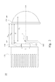
- FIG. 1 illustrates a perspective view of an LED headlight 100 according to one embodiment of this disclosure
- FIG. 2 illustrates a side schematic view of an LED headlight 100 in FIG. 1 (i.e., FIG. 2 shows the main parts' profiles, not the actual proportions or shapes depicted).
- the LED headlight 100 includes at least one LED module 110 , a heat sink 120 , a lens 130 and a shelter 140 .
- the lens 130 has an optical axis OA, a focal length F L , a focal point f, a focal plane FP and an object principal plane PP, wherein the focal length F L is a distance between the object principal plane PP of the lens 130 and the focal point f of the lens 130 , and the focal plane FP extends from the focal point f of the lens 130 and is perpendicular to an optical axis OA passing through a geometrical center of the lens 130 .
- the heat sink 120 is located along the optical axis OA, and a distance D HL between the heat sink 120 and the lens 130 is greater than a distance d′ between the focal point f and the lens 130 .
- the LED module 110 is installed along the optical axis OA of the lens 130 , and positioned in contact with the heat sink 120 .
- a distance D LL between the LED module 110 and the lens 130 is greater than the distance d′ between the focal point f and the lens 130 .
- the LED module 110 has a light-emitting surface 112 .
- the shelter 140 is located along the focal plane FP, and is used to selectively block light beams emitted from the LED module. When the shelter 140 blocks light beams emitted from the LED module, the light emitted from the LED headlight 100 is irradiated to a surface (such as the ground) so as to form a cut-off line thereon.
- the cut-off line is a line projected on the surface to make a distinction between a bright zone and a dark zone of the light pattern, and used to avoid the harm of the glare to the passerby.
- the light beams emitted from the light-emitting surface 112 confronts onto the lens 130 directly, and any light reflecting component (e.g., a reflector) is not necessary to apply within the LED headlight 100 . Therefore, the total volume of the LED headlight 100 in this embodiment can become relatively smaller to fit the future market requirement of vehicle headlights.
- any light reflecting component e.g., a reflector
- FIG. 3 illustrates key components of the LED headlight 100 according to another embodiment of this disclosure, wherein the shelter 140 and heat sink 120 as illustrated in FIG. 1 and FIG. 2 are omitted.
- the light-emitting surface 112 of the LED module 110 is equipped with a maximum width L.
- the maximum width L can be a distance between two opposite sides of the light-emitting surface 112 , and the maximum width L and the focal length F L of the lens 130 satisfy the formula: 0.0351F L ⁇ L ⁇ 0.7279F L .
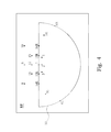
- FIG. 4 illustrates a light pattern of an LED headlight 100 according to another embodiment of this disclosure.
- the light emitted from the light-emitting surface 112 of the LED module 110 is refracted by the lens 130 along a distance D PR and onto the projection surface RP so as to obtain a light pattern S 1 (e.g., an approximately semicircular pattern) as illustrated in FIG. 4 .
- the LED module 110 has a circular light-emitting surface, which is driven by 33 volt, 450 mA to emit along the distance D PR (25 meters) and onto the projection surface RP.
- Table 1 lists measurement results on the projection surface RP in this embodiment and compared with ECE's regulatory requirements (for motorcycle), wherein the measured point 7 is located at an intersection of the optical axis OA of the lens 130 and the projection surface RP, and its luminous intensity requirement is smaller than or equal to 1700 candelas.
- FIG. 5 illustrates a light profile of the LED headlight 100 according to still another embodiment of this disclosure.
- This embodiment is different from the embodiment of FIG. 4 that the light beams emitted from the LED module 110 is refracted by the lens 130 onto the projection surface RP so as to obtain a light pattern S 2 , which has a cut-off line CL.
- the cut-off line CL is a line on the projection surface to make a distinction between a bright zone and a dark zone of the light pattern S 2
- the cut-off line CL is formed mainly by using the shelter 140 to block part of light emitted from the LED module (referring to FIG. 1 and FIG. 2 ).
- the embodiment of FIG. 1 illustrates a light profile of the LED headlight 100 according to still another embodiment of this disclosure.
- the cut-off line CL is a line on the projection surface to make a distinction between a bright zone and a dark zone of the light pattern S 2
- the cut-off line CL is formed mainly by using the shelter 140 to block part of light e
- the horizontal line HL and the vertical line VL divides the projection plane RP into four quadrants, the cutoff line CL is in the first quadrant, and an included angle ⁇ i is formed between the cut-off line CL and the horizontal line HL so as to avoid the harm of the glare (generated by the LED headlight 100 ) to the passerby.
- the angle ⁇ i between the cut-off line CL and the horizontal line HL is, but not being limited to, about 15°.
- table 2 lists measurement results on the projection surface RP in this embodiment and compared with ECE's regulatory requirements (for automobiles).
- the LED module 110 is driven by 35 volt, 1 A to emit along the distance D PR (25 meters) and onto the projection surface RP, wherein the measured point 50V is located at an intersection of the optical axis OA of the lens 130 and the projection surface RP, and its luminous intensity requirement is smaller than or equal to 5100 candelas.
- a first intersection A 1 is formed of the focal plane FP and the emitted light along the (outermost) viewing angle (2 ⁇ L ) of the LED module 110
- a second intersection A 2 is formed of the object principal plane PP of the lens 130 and the optical axis OA.
- a virtual line B is formed between first intersection A 1 and the second intersection A 2 .
- an angle (2 ⁇ ) is formed between the virtual line B and the optical axis OA of the lens 130 .
- the angle (2 ⁇ ) is also referred as “angle of intersection”, and half of the “angle of intersection” is ⁇ .
- a distance between the focal plane FP and the LED module 110 is “d”, and half of the (full) viewing angle of the LED module 110 is ⁇ L .
- the (full) viewing angle (2 ⁇ L ) of the LED module 110 is an angle of intersection between the outermost emitted light of the LED module 110 and the optical axis OA of the lens 130 .
- the LED headlight 100 can be designed in accordance with the equation (1).
- a distance d between the focal plane FP and the LED module 110 also satisfies the following equation (2): 0 ⁇ d ⁇ F L /5 (2)
- the maximum width L of the light-emitting surface 112 of the LED module 110 is affirmative by inputting the focal length F L of the lens 130 , half of the “angle of intersection” ⁇ , and half of the (full) viewing angle ⁇ L into the equation (3) so as to simplify the design process of the LED headlight 100 in compliance with ECE regulations.
- the LED headlight 100 in this embodiment is able to become smaller because the distance “d” between the focal plane FP and the LED module 110 is equal to or less than F L /5(d ⁇ F L /5).
- the distance “d” between the focal plane FP and the LED module 110 is equal to or less than F L /5 (d ⁇ F L /5).
- ⁇ L tan ⁇ 1 [(2 F L tan ⁇ - L )/2 d] (5)
- ⁇ L tan ⁇ 1 [(2 F L tan ⁇ - L )/2 d] (5)
- ⁇ L tan ⁇ 1 [(2 F L tan ⁇ - L )/2 d] (5)
- the distance “d” between the focal plane FP and the LED module 110 can be defined via the focal length F L , the maximum width L of the light-emitting surface 112 , and the characteristics of Lambertian light source, thereby enabling the present embodiment forming a broad and soft light pattern without any surface treatments upon the lens 130 .
- the focal length F L of the lens 130 ranges from about 44.5 millimeters to about 57.5 millimeters, and the lens 130 has a Numerical Aperture ranging from about 0.5 to about 0.55.
- one or more embodiments equipped with the LED headlight 100 are able to consume lower power.
- one or more embodiments equipped with the LED headlight 100 do not necessitate any reflector inside so that there is more space to utilize.
Landscapes
- Engineering & Computer Science (AREA)
- General Engineering & Computer Science (AREA)
- Physics & Mathematics (AREA)
- Microelectronics & Electronic Packaging (AREA)
- Optics & Photonics (AREA)
- Non-Portable Lighting Devices Or Systems Thereof (AREA)
- Led Device Packages (AREA)
Abstract
Description
2F L tan θ=L+2d tan θL
Wherein θ represents half of the angle of intersection between the virtual line and the optical axis of the lens, θL represents half of the viewing angle of the LED module; d represents a distance between the focal plane and the LED module.
| TABLE 1 | ||
| Measured | ECE's Light intensity | Light intensity |
| points | requirements (candelas) | (candelas) measured |
| 1 | 2000~13750 | 7136 |
| 2 | ≥2450 | 8680 |
| 3 | 2000~13750 | 7198 |
| 7 | ≤1700 | 944 |
| 4L | 4R | ≤900 | 258 | 262 |
| 5L | 5R | ≥550 | 646 | 603 |
| |
6R | ≥150 | 307 | 298 |
| 8 + 9 + 10 | ≥150 | 309 |
| 11 + 12 + 13 | ≥300 | 500 |
| |
14R | ≥50 | 619 | 475 |
| |
15R | 100-900 | 828 | 778 |
| TABLE 2 | ||
| Measured | ECE's Light intensity | Light intensity |
| points | requirements (candelas) | (candelas) measured |
| B50L | ≤350 | 342 |
| BR | ≤1750 | 1373 |
| 75R | ≥10100 | 11430 |
| 75L | ≤10600 | 6368 |
| 50L | ≤13200 | 7971 |
| 50R | ≥10100 | 12000 |
| 50V | ≥5100 | 11145 |
| 25L | ≥1700 | 1895 |
| 25R | ≥1700 | 4450 |
| 1 + 2 + 3 | ≥190 | 878 |
| 4 + 5 + 6 | ≥375 | 1664 |
| 7 | ≥65 | 375 |
| 8 | ≥125 | 1361 |
2F L tan θ=L+2d tan θL (1)
The equation (1) can be obtained from two triangles at two sides of the focal plane FP in
0≤d≤F L/5 (2)
2F L tan θ−(2F L/5)tan θL ≤L≤2F L tan θ (3)
(2F L tan θ-L)/2 tan 65°≤d≤(2F L tan θ-L)/2 tan 55° (4)
θL=tan−1[(2F L tan θ-L)/2d] (5)
When the
Claims (10)
2F L tan θ=L+2d tan θL
(2F L tan θ−L)/2 tan 65°≤d≤(2F L tan θ−L)/2 tan 55°.
(2F L tan θ−L)/2 tan 65°≤d≤(2F L tan θ−L)/2 tan 55°
Applications Claiming Priority (6)
| Application Number | Priority Date | Filing Date | Title |
|---|---|---|---|
| TW104102866 | 2015-01-28 | ||
| TW104102866 | 2015-01-28 | ||
| TW104102866A | 2015-01-28 | ||
| TW104118968A TWI554713B (en) | 2015-01-28 | 2015-06-11 | Light emitting diode headlight |
| TW104118968A | 2015-06-11 | ||
| TW104118968 | 2015-06-11 |
Publications (2)
| Publication Number | Publication Date |
|---|---|
| US20160215944A1 US20160215944A1 (en) | 2016-07-28 |
| US10012357B2 true US10012357B2 (en) | 2018-07-03 |
Family
ID=55237538
Family Applications (1)
| Application Number | Title | Priority Date | Filing Date |
|---|---|---|---|
| US14/975,849 Active 2036-09-13 US10012357B2 (en) | 2015-01-28 | 2015-12-20 | Light emitting diode headlight |
Country Status (3)
| Country | Link |
|---|---|
| US (1) | US10012357B2 (en) |
| EP (1) | EP3051201A1 (en) |
| TW (1) | TWI554713B (en) |
Citations (20)
| Publication number | Priority date | Publication date | Assignee | Title |
|---|---|---|---|---|
| US5902039A (en) | 1996-11-14 | 1999-05-11 | Stanley Electric Co., Ltd. | Projector type headlamp |
| US20030107901A1 (en) | 2001-10-15 | 2003-06-12 | Honda Giken Kogyo Kabushiki Kaisha | Projector headlamp |
| US20050018443A1 (en) * | 2003-07-24 | 2005-01-27 | Hironori Tsukamoto | Lamp unit for forming a cut-off line and vehicular headlamp using the same |
| TWI258550B (en) | 2005-10-12 | 2006-07-21 | Automotive Res & Testing Ct | Miniature LED lighting module for LED headlight set |
| TW200726668A (en) | 2006-01-10 | 2007-07-16 | Chungchou Inst Of Technology | A fog lamp |
| TW200838739A (en) | 2007-03-16 | 2008-10-01 | Chungchou Inst Of Technology | Optical system for vehicles forward lighting and a dipped headlight module for the same |
| JP2009064629A (en) | 2007-09-05 | 2009-03-26 | Koito Mfg Co Ltd | Vehicle headlamp |
| JP2009134964A (en) | 2007-11-29 | 2009-06-18 | Stanley Electric Co Ltd | Vehicle headlamp |
| TW200938413A (en) | 2008-03-07 | 2009-09-16 | Chungchou Inst Of Technology | LED vehicle lamp complied with the regulations of four light pattern modes of adaptive front-lighting system |
| US20100046243A1 (en) | 2008-08-20 | 2010-02-25 | Yasushi Yatsuda | Vehicle Lighting Unit and Vehicle Light |
| US8092059B2 (en) * | 2009-06-04 | 2012-01-10 | Stanley Electric Co., Ltd. | Vehicular lighting fixture |
| US20120140505A1 (en) * | 2010-12-02 | 2012-06-07 | Koito Manufacturing Co., Ltd. | Vehicular headlamp |
| US20120275168A1 (en) * | 2011-04-29 | 2012-11-01 | Hella Kgaa Hueck & Co. | Projection headlight with recessed light beam producing section |
| EP2522897A2 (en) | 2011-05-10 | 2012-11-14 | Koito Manufacturing Co., Ltd. | Vehicle headlamp |
| US20130003402A1 (en) * | 2011-06-30 | 2013-01-03 | Phoenix Optronics Corp. | Method of using lens imaging to control angle subtended by multiple hotspots of a vehicle light |
| US8506146B2 (en) | 2010-01-14 | 2013-08-13 | Koito Manufacturing Co., Ltd. | Vehicle head lamp |
| CN103883957A (en) | 2012-12-21 | 2014-06-25 | 欧司朗有限公司 | Vehicle Lighting Device |
| US20140175978A1 (en) * | 2011-09-01 | 2014-06-26 | Koito Manufacturing Co.,Ltd. | Automotive headlamp apparatus |
| TW201432187A (en) | 2013-02-01 | 2014-08-16 | Univ Kun Shan | Light-emitting member of LED vehicle lamp and optical lens thereof |
| US20160238210A1 (en) * | 2013-09-26 | 2016-08-18 | Koito Manufacturing Co., Ltd. | Vehicle lamp control system |
-
2015
- 2015-06-11 TW TW104118968A patent/TWI554713B/en active
- 2015-12-20 US US14/975,849 patent/US10012357B2/en active Active
-
2016
- 2016-01-26 EP EP16152683.5A patent/EP3051201A1/en not_active Withdrawn
Patent Citations (23)
| Publication number | Priority date | Publication date | Assignee | Title |
|---|---|---|---|---|
| US5902039A (en) | 1996-11-14 | 1999-05-11 | Stanley Electric Co., Ltd. | Projector type headlamp |
| US20030107901A1 (en) | 2001-10-15 | 2003-06-12 | Honda Giken Kogyo Kabushiki Kaisha | Projector headlamp |
| US20050018443A1 (en) * | 2003-07-24 | 2005-01-27 | Hironori Tsukamoto | Lamp unit for forming a cut-off line and vehicular headlamp using the same |
| TWI258550B (en) | 2005-10-12 | 2006-07-21 | Automotive Res & Testing Ct | Miniature LED lighting module for LED headlight set |
| TW200726668A (en) | 2006-01-10 | 2007-07-16 | Chungchou Inst Of Technology | A fog lamp |
| TWI296585B (en) | 2006-01-10 | 2008-05-11 | Chungchou Inst Of Technology | A fog lamp |
| TW200838739A (en) | 2007-03-16 | 2008-10-01 | Chungchou Inst Of Technology | Optical system for vehicles forward lighting and a dipped headlight module for the same |
| JP2009064629A (en) | 2007-09-05 | 2009-03-26 | Koito Mfg Co Ltd | Vehicle headlamp |
| DE102008046107A1 (en) | 2007-09-05 | 2009-04-02 | Koito Manufacturing Co., Ltd. | vehicle light |
| JP2009134964A (en) | 2007-11-29 | 2009-06-18 | Stanley Electric Co Ltd | Vehicle headlamp |
| TW200938413A (en) | 2008-03-07 | 2009-09-16 | Chungchou Inst Of Technology | LED vehicle lamp complied with the regulations of four light pattern modes of adaptive front-lighting system |
| US20100046243A1 (en) | 2008-08-20 | 2010-02-25 | Yasushi Yatsuda | Vehicle Lighting Unit and Vehicle Light |
| US8092059B2 (en) * | 2009-06-04 | 2012-01-10 | Stanley Electric Co., Ltd. | Vehicular lighting fixture |
| US8506146B2 (en) | 2010-01-14 | 2013-08-13 | Koito Manufacturing Co., Ltd. | Vehicle head lamp |
| US20120140505A1 (en) * | 2010-12-02 | 2012-06-07 | Koito Manufacturing Co., Ltd. | Vehicular headlamp |
| US20120275168A1 (en) * | 2011-04-29 | 2012-11-01 | Hella Kgaa Hueck & Co. | Projection headlight with recessed light beam producing section |
| EP2522897A2 (en) | 2011-05-10 | 2012-11-14 | Koito Manufacturing Co., Ltd. | Vehicle headlamp |
| US20130003402A1 (en) * | 2011-06-30 | 2013-01-03 | Phoenix Optronics Corp. | Method of using lens imaging to control angle subtended by multiple hotspots of a vehicle light |
| US20140175978A1 (en) * | 2011-09-01 | 2014-06-26 | Koito Manufacturing Co.,Ltd. | Automotive headlamp apparatus |
| CN103883957A (en) | 2012-12-21 | 2014-06-25 | 欧司朗有限公司 | Vehicle Lighting Device |
| DE102012224345A1 (en) | 2012-12-21 | 2014-06-26 | Osram Gmbh | Vehicle lighting device |
| TW201432187A (en) | 2013-02-01 | 2014-08-16 | Univ Kun Shan | Light-emitting member of LED vehicle lamp and optical lens thereof |
| US20160238210A1 (en) * | 2013-09-26 | 2016-08-18 | Koito Manufacturing Co., Ltd. | Vehicle lamp control system |
Also Published As
| Publication number | Publication date |
|---|---|
| TWI554713B (en) | 2016-10-21 |
| US20160215944A1 (en) | 2016-07-28 |
| CN105841062A (en) | 2016-08-10 |
| EP3051201A1 (en) | 2016-08-03 |
| TW201627594A (en) | 2016-08-01 |
Similar Documents
| Publication | Publication Date | Title |
|---|---|---|
| US10359169B2 (en) | Lamp unit and vehicle headlamp | |
| US9803821B2 (en) | Vehicle-mounted headlamp | |
| US10260694B2 (en) | Headlight for vehicle and vehicle using the same | |
| KR101925849B1 (en) | Vehicle lighting unit | |
| TWI650256B (en) | Smart headlight | |
| CN104235719B (en) | Lamps apparatus for vehicle | |
| US8888344B2 (en) | Vehicle lamp unit | |
| US10144339B2 (en) | Vehicle lamp device and light cut-off structure thereof | |
| JP2013030728A (en) | Light source module | |
| KR20130010836A (en) | Vehicular headlamp | |
| CN104100899B (en) | Embody many array LED chips and its head lamp of dead line | |
| KR20220014690A (en) | Lamp for vehicle | |
| JP6030864B2 (en) | Lamp unit and projection lens | |
| CN104421795B (en) | Lamps apparatus for vehicle | |
| CN101619823A (en) | LED street lamp | |
| US20190154225A1 (en) | Vehicle headlight | |
| US10012357B2 (en) | Light emitting diode headlight | |
| JP2014235836A (en) | Vehicle lighting appliance | |
| JP5630622B2 (en) | Vehicle lighting | |
| TW201425815A (en) | Lighting emitting diode automobile lamp | |
| JP5298395B2 (en) | Vehicle headlamp | |
| JP2016115583A (en) | Vehicular lighting unit | |
| JP6492675B2 (en) | Vehicle lighting | |
| JP2013048107A (en) | Vehicle headlight | |
| KR102250659B1 (en) | Optical lens for vehicles and vehicle lamp using the same |
Legal Events
| Date | Code | Title | Description |
|---|---|---|---|
| AS | Assignment |
Owner name: LEXTAR ELECTRONICS CORPORATION, TAIWAN Free format text: ASSIGNMENT OF ASSIGNORS INTEREST;ASSIGNORS:LIN, SHIH-KAI;LIN, YU-MIN;REEL/FRAME:037336/0188 Effective date: 20151019 |
|
| STCF | Information on status: patent grant |
Free format text: PATENTED CASE |
|
| MAFP | Maintenance fee payment |
Free format text: PAYMENT OF MAINTENANCE FEE, 4TH YEAR, LARGE ENTITY (ORIGINAL EVENT CODE: M1551); ENTITY STATUS OF PATENT OWNER: LARGE ENTITY Year of fee payment: 4 |
|
| MAFP | Maintenance fee payment |
Free format text: PAYMENT OF MAINTENANCE FEE, 8TH YEAR, LARGE ENTITY (ORIGINAL EVENT CODE: M1552); ENTITY STATUS OF PATENT OWNER: LARGE ENTITY Year of fee payment: 8 |