US10001646B2 - Head-up display - Google Patents
Head-up display Download PDFInfo
- Publication number
- US10001646B2 US10001646B2 US14/710,941 US201514710941A US10001646B2 US 10001646 B2 US10001646 B2 US 10001646B2 US 201514710941 A US201514710941 A US 201514710941A US 10001646 B2 US10001646 B2 US 10001646B2
- Authority
- US
- United States
- Prior art keywords
- concave mirror
- angle
- scanner
- incidence
- display light
- Prior art date
- Legal status (The legal status is an assumption and is not a legal conclusion. Google has not performed a legal analysis and makes no representation as to the accuracy of the status listed.)
- Active, expires
Links
Images


Classifications
-
- G—PHYSICS
- G02—OPTICS
- G02B—OPTICAL ELEMENTS, SYSTEMS OR APPARATUS
- G02B27/00—Optical systems or apparatus not provided for by any of the groups G02B1/00 - G02B26/00, G02B30/00
- G02B27/01—Head-up displays
-
- G—PHYSICS
- G02—OPTICS
- G02B—OPTICAL ELEMENTS, SYSTEMS OR APPARATUS
- G02B26/00—Optical devices or arrangements for the control of light using movable or deformable optical elements
- G02B26/08—Optical devices or arrangements for the control of light using movable or deformable optical elements for controlling the direction of light
- G02B26/10—Scanning systems
-
- G—PHYSICS
- G02—OPTICS
- G02B—OPTICAL ELEMENTS, SYSTEMS OR APPARATUS
- G02B27/00—Optical systems or apparatus not provided for by any of the groups G02B1/00 - G02B26/00, G02B30/00
- G02B27/01—Head-up displays
- G02B27/0101—Head-up displays characterised by optical features
-
- G—PHYSICS
- G02—OPTICS
- G02B—OPTICAL ELEMENTS, SYSTEMS OR APPARATUS
- G02B27/00—Optical systems or apparatus not provided for by any of the groups G02B1/00 - G02B26/00, G02B30/00
- G02B27/01—Head-up displays
- G02B27/0101—Head-up displays characterised by optical features
- G02B2027/011—Head-up displays characterised by optical features comprising device for correcting geometrical aberrations, distortion
-
- G—PHYSICS
- G02—OPTICS
- G02B—OPTICAL ELEMENTS, SYSTEMS OR APPARATUS
- G02B27/00—Optical systems or apparatus not provided for by any of the groups G02B1/00 - G02B26/00, G02B30/00
- G02B27/01—Head-up displays
- G02B27/0101—Head-up displays characterised by optical features
- G02B2027/014—Head-up displays characterised by optical features comprising information/image processing systems
Definitions
- the present disclosure relates to a head-up display that projects display light to a projection member.
- a head-up display when an image displayed by a display unit is expanded by a concave mirror and the like so as to be displayed, it is understood that by producing an image with the display unit such that distortions in the image are offset, an image with reduced distortion may be provided to a user (refer to, e.g., JP 5050862B).
- the present disclosure relates to a head-up display that projects display light to a projection member.
- the head-up display includes a beam generator that emits a beam of light as the display light, a scanner including a moveable reflective surface, the scanner receiving the display light from the beam generator and scanning the display light, an optical actuator that integrally rotates the beam generator and the scanner to change a scanner angle of incidence of the display light at the scanner, a screen that receives the display light from the scanner and reflects the display light, a concave mirror that receives the display light from the screen and reflects and expands the display light to the projection member, a concave mirror actuator that changes, based on external instructions, a concave mirror angle of incidence of the display light at the concave mirror by rotating the concave mirror, and a controller including a CPU and a memory.
- the display light travels between the beam generator, the scanner, the screen, the concave mirror, and the projection member substantially along a common plane.
- the controller is programmed to drive, based on the concave mirror angle of incidence, the optical actuator to change the scanner angle of incidence such that display light distortions generated at the concave mirror are offset by display light distortions generated at the scanner.
- FIG. 1 is a side view of the schematic structure of a head-up display according to an aspect of the present disclosure.
- FIG. 2 is a block diagram of the schematic structure of the head-up display of FIG. 1 .
- FIGS. 3A and 3B are views of an overview of image distortion generated by a scanner.
- FIGS. 4A, 4B, 4C, and 4D show an overview of image distortion generated by a concave mirror.
- FIGS. 5A and 5B show first details of image distortion generated by the scanner of FIG. 3 .
- FIGS. 6A and 6B show second details of image distortion generated by the scanner of FIG. 3 .
- FIGS. 7A and 7B show first details of image distortion generated by the concave mirror of FIG. 4 .
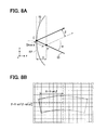
- FIGS. 8A and 8B show second details of image distortion generated by the concave mirror of FIG. 4 .
- FIGS. 9A and 9B show first details of image distortion generated by the scanner of FIG. 3 according to a modified embodiment of the present disclosure.
- FIG. 10 shows second details of image distortion generated by the scanner of FIG. 3 according to the modified embodiment of the present disclosure.
- FIG. 11 shows the relationship between change in an angle of incidence at the scanner of FIG. 3 and an angle of emergence of the concave mirror of FIG. 4 .
- a head-up display 1 may be, e.g., mounted in a vehicle.
- the head-up display 1 includes a controller 10 , a concave mirror 15 , a screen 18 , a concave mirror actuator 33 , a drawing unit 40 , and an optical actuator 43 .
- the optical axis 31 is a schematic representation of the center of the optical path taken by an image displayed from the screen 18 .
- the drawing unit 40 includes a beam generator 41 , a scanner 42 , and the optical actuator 43 .
- the beam generator 41 generates a beam of light as, e.g., a laser, and illuminates the beam onto the scanner 42 .
- the scanner 42 may be a MEMS (Micro Electro-Mechanical System) type micro mirror device which, using a beam input thereto at a given angle of incidence (i.e., a scanner angle of incidence), scans the beam along two orthogonal axes by moving a moveable reflective surface.
- a MEMS Micro Electro-Mechanical System
- the scanner 42 would scan the beam in two dimensions: a top-down direction in FIG. 1 , as well as in a direction into and out of the plane of FIG. 1 . In other words, the scanning occurs along a direction orthogonal to the plane of FIG. 1 .
- the optical actuator 43 is a motor or the like that changes an angle of the drawing unit 40 . Accordingly, the optical actuator 43 drives the drawing unit 40 to change the angle of incidence of the beam with respect to the scanner 42 .
- the drawing unit 40 outputs an image as display light, which visually forms an image on a surface (diffusion region) of the screen 18 .
- This image is reflected and expanded by the concave mirror 15 and projected onto a windshield (projection member) 21 of a vehicle.
- the concave mirror 15 is a typical concave mirror as would be understood by a person of ordinary skill in the art.
- the image arrives at a viewpoint 25 of a driver (passenger).
- the viewpoint 25 is positioned within an eye zone 23 .
- the driver is able to see the image as a virtual image (virtual display image) 27 positioned at a point beyond the windshield 21 .
- the eye zone 23 is an area where the driver is able to visually recognize the image. Further, the position of the viewpoint 25 can be adjusted according to the angle of the concave mirror 15 .
- the angle of the concave mirror 15 is changed by the concave mirror actuator 33 .
- the concave mirror actuator 33 may include a motor, such as a stepper motor, and a gear assembly driven by the motor.
- the viewpoint 25 of the driver will move upward to position A shown in FIG. 1 .
- the viewpoint 25 of the driver will move downward to position B shown in FIG. 1 .
- the position of the viewpoint 25 may be adjusted according to the viewing position (sitting height) of the driver.
- the beam is preferably set to be emitted, scanned, and reflected along a common plane (a y-z plane).
- optical axes 61 , 62 , 63 , and 64 illustrated in FIG. 1 are preferably set to be coplanar.
- optical axes 61 , 62 , 63 , and 64 are not necessarily exactly coplanar, and only need to be coplanar insofar as image distortions in the direction into and out of the plane of FIG. 1 are minimized so as to avoid causing discomfort to a human observer, i.e., such that a human observer is unable to clearly discern whether these distortions exist.
- image distortions in a direction along the plane (i.e., the y-z plane) of FIG. 1 may be isolated and reduced in accordance with the preferred embodiments of the present disclosure as will be explained below.
- FIG. 2 illustrates an exemplary configuration of electrical connections in the head-up display 1 .
- the concave mirror actuator 33 includes an angle detector 13 that detects the angle of the concave mirror 15 .
- the angle detector 13 may be an encoder which sends the detected angle as a signal to the controller 10 .
- the controller 10 includes a computer having a CPU 11 and a memory 12 .
- the memory 12 may be ROM, RAM, or the like.
- the controller 10 operates the drawing unit 40 to display an image on the screen 18 .
- the controller 10 when the controller 10 receives external instructions, such as user instructions to change the viewing position of the image by raising or lowering the viewpoint 25 , the controller 10 operates the concave mirror actuator 33 , based on the external instructions, to change the angle of the concave mirror 15 .
- the controller 10 drives and operates the optical actuator 43 to an appropriate angle. That is, the controller 10 drives and operates the optical actuator 43 to satisfy Equation (7) which will be discussed below.
- FIGS. 3A, 3B and 4A-4D illustrate a relationship between image distortions generated at the scanner 42 and image distortions generated at the concave mirror 15 .
- a beam incident light
- the angle between the incident light and the emergent light is 2 ⁇ .
- Half of this angle, ⁇ is defined as the angle of incidence.
- FIGS. 4A-4D illustrate a distortion cancelling mechanism based on the above described phenomenon.
- This distortion cancelling mechanism is used in the present embodiment as will be discussed further below.
- FIG. 4A shows a configuration where the angle of incidence ⁇ into the scanner 42 is 0 degrees. As such, no distortions are present in the image scanned onto the screen 18 .
- FIG. 4B when the scanned light is reflected to the concave mirror 15 and is expanded thereby, substantially all of the image distortions generated by the concave mirror 15 remain in the resulting virtual image 27 .
- FIG. 4C shows a configuration where the angle of incidence ⁇ into the scanner 42 is 37 degrees.
- upward image distortions are present in the image scanned on the screen 18 .
- FIG. 4D when the scanned light is reflected to the concave mirror 15 and is expanded thereby, image distortions generated by the concave mirror 15 are substantially cancelled out with image distortions generated by the scanner 42 .
- the virtual image 27 exhibits substantially no image distortions.
- angles of incidence ⁇ of 0 degrees and 37 degrees are intended to be non-limiting examples, and are arbitrarily chosen to illustrate a distortion canceling mechanism used in the present embodiment.
- FIG. 5A illustrates a configuration with an angle of incidence ⁇ .
- FIG. 5B scanning in the horizontal direction (i.e, an x direction) will be considered.
- an angle between the incident light and the emergent light in the horizontal direction is a horizontal scanning angle ⁇ .
- FIG. 5B shows that if the distance to the screen 18 is normalized to a unit distance and represented as cos ⁇ then the horizontal dimension of imaged area is cos ⁇ *tan ⁇ .
- the dashed arrow in FIG. 6A shows that the vertical dimension of the imaged area is sin ⁇ .
- the actual vertical dimension of the imaged area is extended. Specifically, the vertical dimension of the imaged area increases with the horizontal scanning angle ⁇ . In this case the actual vertical dimension of the imaged area is sin ⁇ /cos ⁇ .
- an amount of warp (distortion) ⁇ generated by the scanner 42 increases as the angle of incidence ⁇ increases.
- the amount of warp ⁇ is defined as the change in the vertical dimension of the imaged area, which is sin ⁇ /cos ⁇ minus sin ⁇ , divided by the horizontal dimension of the imaged area, which is cos ⁇ *tan ⁇ . Simplified, the amount of warp ⁇ is expressed in equation (1):
- the beam having been scanned by the scanner 42 , strikes an area of the concave mirror 15 .
- a point C near the center of the concave mirror 15 is where the optical axis 63 of the scanned light strikes the concave mirror 15
- a point P at a distal portion of the concave mirror 15 is the edge of the scanned light striking the concave mirror 15 .
- the scanned light spans, on one side of the point C, between the points C and P.
- FIG. 7B shows a schematic view of the concave mirror 15 .
- the horizontal direction (x direction) is the left to right direction in FIG. 7B .
- point O is defined as the center of curvature of the concave mirror 15 .
- an angle ⁇ is defined as the angle between a line connecting points O and P, and a line connecting points O and C.
- a distance H between point P and the horizontal center of the scanned light is expressed as R*sin ⁇ .
- the scanned light has a width of 2H in the horizontal direction at the concave mirror 15 .
- an offset height D is defined between the points P and C. In other words, the height D is measured from the point P to a reference plane RP tangential to the concave mirror 15 at the point C, as shown in FIG. 7B .
- the horizontal direction (x direction) is the direction into and out of the plane of paper.
- the optical axis 63 of the scanned light passes through a point P′.
- the point P′ is a projection of the point P onto the optical axis 63 , such that the point P′ is also offset from the point C by the height D.
- the height D is also a distance between the point P′ and the reference plane RP.
- the optical axis 63 of the scanned light passes through the point P′ earlier than the point C, by a distance difference of D/cos ⁇ .
- an optical path gap ⁇ exists between a hypothetical reflection of the scanned light at the point P′ (shown as a dashed line) and the reflection of the scanned light at the point C (shown as a solid line).
- This optical path gap ⁇ manifests as image distortions in the virtual image 27 .
- the scanned light is not actually reflected at the point P′.
- the point P′ is a geometric representation used in measuring the amount of image distortion caused by the offset height D between the points P and C.
- the optical path gap ⁇ is measured between the reflections at the points P′ and C, the optical path gap ⁇ ultimately manifests due to the offset height D between the points P and C.
- representation of the optical path gap ⁇ is described in detail.
- optical path gap ⁇ Given this approximation and the relationship between the optical path gap ⁇ and the height D shown in FIG. 8A , the optical path gap ⁇ can be expressed in equation (5):
- the amount of warp ⁇ generated by the concave mirror 15 increases as the angle of incidence ⁇ at the concave mirror 15 increases.
- the amount of warp ⁇ in this case is measured in the downward direction, and is equal to the optical path gap ⁇ divided by the horizontal dimension of the imaged area, H (i.e., R*sin ⁇ ).
- the amount of warp ⁇ generated by the concave mirror 15 and the amount of warp ⁇ generated by the scanner 42 may be set to be equal in magnitude and opposite in direction.
- the amount of curved distortion in the virtual image 27 may be minimized.
- the angle of incidence ⁇ is set to satisfy equation (7): tan ⁇ (1 ⁇ cos ⁇ )/sin ⁇ sin ⁇ H/R (7)
- the terms ⁇ , H, and R are known constants as explained above.
- the angle of incidence ⁇ at the concave mirror is detected by the angle detector 13 and sent to the controller 10 . Accordingly, the controller 10 is programmed to drive the optical actuator 43 to change the angle of incidence ⁇ at the scanner 42 based on the above equation (7) (i.e., based on the angle of incidence ⁇ at the concave mirror 15 ), such that display light distortions generated at the concave mirror 15 are offset by display light distortions generated at the scanner 42 .
- the optical actuator 43 adjusts the angle of incidence ⁇ at the scanner 42 with respect to the angle of incidence ⁇ at the concave mirror 15 to cancel out of the distortions generated at the concave mirror 15 with the distortions generated at the scanner 42 in the opposite direction. Accordingly, distortion of the display light can be suppressed.
- all distortions generated by the concave mirror 15 and the scanner 42 are considered and preferably suppressed.
- a default viewpoint 25 distortions in the virtual image 27 may already be minimized or otherwise at a low level.
- the amount of image distortion at a default viewpoint 25 may be measured, e.g., at the time of manufacturing. Then, this default amount of image distortion may be corrected by software means or other optical means as would be understood by a skilled artisan.
- the default viewpoint 25 may be set in accordance with, e.g., an average driver sitting height.
- a user may wish to change the default viewpoint due to, e.g., the user being taller than average, or simply due to the user's personal preference.
- the controller 10 controls the concave mirror driver 33 to adjust the angle of incidence ⁇ at the concave mirror 15 by rotating the concave mirror 15 .
- the default angle of incidence ⁇ at the concave mirror 15 is disturbed, and new distortions will be generated at the concave mirror 15 .
- these new distortions are preferably isolated and reduced.
- the default viewpoint 25 refers to a configuration where a default concave mirror angle of incidence at the concave mirror 15 is ⁇ and a default scanner angle of incidence at the scanner 42 is ⁇ .
- the controller 10 operates the optical actuator 43 to change the angle of incidence ⁇ .
- the angle of incidence ⁇ is changed by a second angle change ⁇ such that image distortions caused by the first angle change ⁇ cancels out with image distortions caused by the second angle change ⁇ .
- FIGS. 9A, 9B, and 10 illustrate a case where the angle of incidence at the scanner 42 is ⁇ + ⁇ .
- the angle of incidence into the scanner 42 is adjusted by ⁇ .
- a difference A in the amount of warp ⁇ , which is caused by changing the angle of incidence at the scanner 42 from “ ⁇ ” to “ ⁇ + ⁇ ”, is calculated by subtracting equation (8) from equation (9), and is expressed in equation (10): (tan( ⁇ + ⁇ ) ⁇ tan ⁇ ) ⁇ (1 ⁇ cos ⁇ )/sin ⁇ (10)
- the image distortions caused by changing the angle of incidence at the scanner 42 from ⁇ to ⁇ + ⁇ are set to cancel out with the image distortions caused by changing the angle of incidence at the concave mirror 15 from ⁇ to ⁇ + ⁇ (i.e., the right side of equation 14).
- the terms ⁇ , H, and R are constants as discussed in the first embodiment.
- the terms ⁇ , ⁇ , and ⁇ are known as discussed above.
- the only unknown term is ⁇ , which may be computed by the controller 10 .
- the controller 10 then operates the optical actuator 43 such that the angle of incidence at the scanner 42 is changed to ⁇ + ⁇ that satisfies the equation (14). As a result, new distortions caused by changing the angle of incidence ⁇ at the concave mirror 15 are minimized.
- the change in angle ⁇ may be set to be proportional to the change in angle ⁇ , in order to simplify computations by the controller 10 .
- FIG. 11 illustrates a configuration where the change in angle ⁇ is set to be equal to the change in angle ⁇ .
- the controller 10 operates the optical actuator 43 to change the angle of incidence ⁇ at the scanner 42 by ⁇ , such that ⁇ equals ⁇ .
- a change in the angle of emergence ⁇ implies an equal change in the angle incidence ⁇ .
- the angle of incidence ⁇ at the concave mirror 15 changes by ⁇ , where ⁇ , ⁇ , and ⁇ are all equal.
- a link mechanism (not illustrated) may be used to control the angle of incidence ⁇ at the scanner 42 .
- the angles of incidence ⁇ and ⁇ , at the default viewpoint 25 are set to satisfy equation (15) above.
- a link mechanism may mechanically link the concave mirror 15 and the scanner 42 together, such that a change in the angle of incidence ⁇ at the concave mirror 15 results in a change in the angle of incidence ⁇ at the scanner 42 , where ⁇ equals ⁇ .
- the controller 10 only needs to drive the concave mirror actuator 33 to rotate the concave mirror 15 , and any new distortions caused by the rotation is automatically canceled by the link mechanism. As a result, the controller 10 does not need to specifically control the optical actuator 43 , and computations by the controller 10 are further simplified.
- equation (15) is derived when ⁇ is set to equal ⁇ . It is contemplated that any predictable relationship between ⁇ and ⁇ may be applied, such that ⁇ is proportional to ⁇ . Then, equation (15) above may be re-derived in view of this predictable relationship. As a result, computations by the controller 10 may be simplified.
- screen 18 may be a diffuse reflection type screen, or a transmission type screen.
- 35 USC 112(f) or 35 USC 112(6) is expressly defined as being invoked for a limitation in the claim only when the exact phrase “means for” or the exact phrase “step for” is recited at the beginning of such limitation in the claim; if such exact phrase is not used in a limitation in the claim, then 35 USC(f) or 35 USC 112(6) is not invoked.
Landscapes
- Physics & Mathematics (AREA)
- General Physics & Mathematics (AREA)
- Optics & Photonics (AREA)
- Fittings On The Vehicle Exterior For Carrying Loads, And Devices For Holding Or Mounting Articles (AREA)
- Instrument Panels (AREA)
- Mechanical Optical Scanning Systems (AREA)
Abstract
Description
D=R·(1−cos β) (2)
cos β=(1−sin2 β)1/2≈1−sin2 β/2 (3)
D=R·sin2 β/2 (4)
γ=δ/(R·sin γ)≈sin α·sin β=sin α·H/R (6)
tan θ·(1−cos ϕ)/sin ϕ≈sin α·H/R (7)
sin θ·(1/cos ϕ−1)/(cos θ·tan ϕ)=tan θ·(1−cos ϕ)/sin ϕ (8)
tan(θ+Δθ)·(1−cos ϕ)/sin ϕ (9)
(tan(θ+Δθ)−tan θ)·(1−cos ϕ)/sin ϕ (10)
A=(Δθ/cos2 θ)·(1−cos ϕ)/sin ϕ (11)
sin(α+Δα)·H/R (12)
(sin(α+Δα)−sin α)·H/R=Δα·cos α·H/R (13)
Δθ·(1−cos ϕ)/sin ϕ/cos2 θ=Δα·cos α·H/R (14)
(1−cos ϕ)/sin ϕ/cos2 θ=cos α·H/R (15)
Claims (2)
tan θ·(1−cos ϕ)/sin ϕ≈sin α·H/R.
Applications Claiming Priority (2)
| Application Number | Priority Date | Filing Date | Title |
|---|---|---|---|
| JP2014-100432 | 2014-05-14 | ||
| JP2014100432 | 2014-05-14 |
Publications (2)
| Publication Number | Publication Date |
|---|---|
| US20150331239A1 US20150331239A1 (en) | 2015-11-19 |
| US10001646B2 true US10001646B2 (en) | 2018-06-19 |
Family
ID=54538374
Family Applications (1)
| Application Number | Title | Priority Date | Filing Date |
|---|---|---|---|
| US14/710,941 Active 2036-01-02 US10001646B2 (en) | 2014-05-14 | 2015-05-13 | Head-up display |
Country Status (2)
| Country | Link |
|---|---|
| US (1) | US10001646B2 (en) |
| JP (1) | JP6428477B2 (en) |
Cited By (1)
| Publication number | Priority date | Publication date | Assignee | Title |
|---|---|---|---|---|
| US10527919B2 (en) * | 2017-05-31 | 2020-01-07 | Panasonic Intellectual Property Management Co., Ltd. | Display device |
Families Citing this family (17)
| Publication number | Priority date | Publication date | Assignee | Title |
|---|---|---|---|---|
| DE112015004377T5 (en) * | 2014-09-26 | 2017-06-08 | Yazaki Corporation | HEAD-UP DISPLAY DEVICE |
| DE102016203185A1 (en) * | 2015-03-11 | 2016-09-15 | Hyundai Mobis Co., Ltd. | Head-up display and control method for it |
| US10989929B2 (en) * | 2016-02-05 | 2021-04-27 | Maxell, Ltd. | Head-up display apparatus |
| JP2017159745A (en) * | 2016-03-08 | 2017-09-14 | パイオニア株式会社 | Image displaying device, image displaying method and program |
| US10274726B2 (en) * | 2016-04-13 | 2019-04-30 | Panasonic Automotive Systems Company Of America, Division Of Panasonic Corporation Of North America | Dynamic eyebox correction for automotive head-up display |
| JP2018025693A (en) * | 2016-08-10 | 2018-02-15 | パナソニックIpマネジメント株式会社 | Display device |
| DE102016117851A1 (en) * | 2016-09-22 | 2018-03-22 | Valeo Schalter Und Sensoren Gmbh | Transmitting device for an optical detection device, optical detection device, motor vehicle and method |
| CN107870421A (en) * | 2016-09-27 | 2018-04-03 | 上海蔚兰动力科技有限公司 | Adjustable reflector for head-up display device and head-up display device including same |
| JP6845988B2 (en) * | 2017-01-26 | 2021-03-24 | 日本精機株式会社 | Head-up display |
| JP6760188B2 (en) * | 2017-04-05 | 2020-09-23 | 株式会社デンソー | Head-up display device |
| KR101934294B1 (en) * | 2017-09-05 | 2019-01-02 | 엘지전자 주식회사 | Display device and vehicle comprising the same |
| JP7140504B2 (en) * | 2018-02-14 | 2022-09-21 | 矢崎総業株式会社 | projection display |
| CN110365952B (en) | 2018-04-11 | 2022-05-31 | 京东方科技集团股份有限公司 | Visual angle testing method and system for projection display device |
| WO2019225571A1 (en) * | 2018-05-23 | 2019-11-28 | 日本精機株式会社 | Head-up display device |
| CN109683325A (en) * | 2019-02-03 | 2019-04-26 | 尤祥铭 | It is a kind of to look squarely tool of reading and writing |
| JP2023003234A (en) * | 2021-06-23 | 2023-01-11 | 株式会社デンソー | head-up display device |
| WO2025230057A1 (en) * | 2024-04-30 | 2025-11-06 | 엘지전자 주식회사 | Head-up display |
Citations (5)
| Publication number | Priority date | Publication date | Assignee | Title |
|---|---|---|---|---|
| JPH1130764A (en) | 1997-07-11 | 1999-02-02 | Shimadzu Corp | Display device |
| US20050157398A1 (en) | 2004-01-15 | 2005-07-21 | Toshiyuki Nagaoka | Head-up display mounted in vehicles, vehicles provided with the same and method of manufacturing the vehicles |
| US7535613B2 (en) * | 2006-04-21 | 2009-05-19 | Hb Electronics Co., Ltd. | Scanning laser display apparatus using laser diode array directed to and corresponding with condensing means of plane mirrors |
| JP2009163122A (en) | 2008-01-09 | 2009-07-23 | Denso Corp | Image forming device |
| US20130050655A1 (en) * | 2011-08-29 | 2013-02-28 | Denso Corporation | Head-up display apparatus, screen member, manufacturing method thereof and image projecting method |
Family Cites Families (5)
| Publication number | Priority date | Publication date | Assignee | Title |
|---|---|---|---|---|
| CN102656501B (en) * | 2009-12-14 | 2014-07-02 | 松下电器产业株式会社 | Transmissive display device |
| EP2728394A4 (en) * | 2011-07-01 | 2015-01-21 | Pioneer Corp | Display device |
| JP2013061554A (en) * | 2011-09-14 | 2013-04-04 | Ricoh Co Ltd | Image forming apparatus, and vehicle with image forming apparatus mounted thereon |
| JP6107153B2 (en) * | 2012-03-28 | 2017-04-05 | 日本精機株式会社 | Vehicle display device |
| JP5772841B2 (en) * | 2013-01-23 | 2015-09-02 | 株式会社デンソー | Vehicle display device |
-
2015
- 2015-05-13 US US14/710,941 patent/US10001646B2/en active Active
- 2015-05-14 JP JP2015099045A patent/JP6428477B2/en active Active
Patent Citations (6)
| Publication number | Priority date | Publication date | Assignee | Title |
|---|---|---|---|---|
| JPH1130764A (en) | 1997-07-11 | 1999-02-02 | Shimadzu Corp | Display device |
| US20050157398A1 (en) | 2004-01-15 | 2005-07-21 | Toshiyuki Nagaoka | Head-up display mounted in vehicles, vehicles provided with the same and method of manufacturing the vehicles |
| US7535613B2 (en) * | 2006-04-21 | 2009-05-19 | Hb Electronics Co., Ltd. | Scanning laser display apparatus using laser diode array directed to and corresponding with condensing means of plane mirrors |
| JP2009163122A (en) | 2008-01-09 | 2009-07-23 | Denso Corp | Image forming device |
| JP5050862B2 (en) | 2008-01-09 | 2012-10-17 | 株式会社デンソー | Image forming apparatus |
| US20130050655A1 (en) * | 2011-08-29 | 2013-02-28 | Denso Corporation | Head-up display apparatus, screen member, manufacturing method thereof and image projecting method |
Cited By (1)
| Publication number | Priority date | Publication date | Assignee | Title |
|---|---|---|---|---|
| US10527919B2 (en) * | 2017-05-31 | 2020-01-07 | Panasonic Intellectual Property Management Co., Ltd. | Display device |
Also Published As
| Publication number | Publication date |
|---|---|
| US20150331239A1 (en) | 2015-11-19 |
| JP6428477B2 (en) | 2018-11-28 |
| JP2015232702A (en) | 2015-12-24 |
Similar Documents
| Publication | Publication Date | Title |
|---|---|---|
| US10001646B2 (en) | Head-up display | |
| US10473929B2 (en) | Image projector | |
| EP3388884B1 (en) | Display apparatus and display unit | |
| EP3088935B1 (en) | Image display apparatus and object apparatus | |
| JP7167500B2 (en) | Mobile devices, image projection devices, head-up displays, laser headlamps, head-mounted displays, object recognition devices, and vehicles | |
| JP5594272B2 (en) | Head-up display device | |
| EP2944986B1 (en) | Image display apparatus and image display system | |
| JP7029605B2 (en) | Head-up display | |
| CN108369342B (en) | Optical scanning equipment, image display equipment and vehicles | |
| CN110709753A (en) | Display device and method for projecting display information in a vehicle | |
| JP6874659B2 (en) | Vehicle display device and vehicle display system | |
| JP6888785B2 (en) | In-vehicle display device | |
| JP6830182B2 (en) | Image projection device | |
| WO2022210362A1 (en) | Image projection device | |
| US20200409144A1 (en) | Virtual-image display device | |
| WO2018105585A1 (en) | Head-up display | |
| US11867902B2 (en) | Display device, head-up display, moving body, and light guide panel | |
| WO2018186149A1 (en) | Head-up display system, and mobile object provided with head-up display system | |
| US20250020924A1 (en) | Head-up display device | |
| EP4414770A1 (en) | Image projecting device and image projecting method | |
| CN119836592A (en) | Head-up display device | |
| CN117806000A (en) | Vehicle display device | |
| JP5753590B2 (en) | Head-up display and control method | |
| EP4664185A1 (en) | Image projection device | |
| US12379587B2 (en) | Light deflector, image projection apparatus, laser headlamp, head-mounted display, distance measurement apparatus, and mobile object |
Legal Events
| Date | Code | Title | Description |
|---|---|---|---|
| AS | Assignment |
Owner name: DENSO CORPORATION, JAPAN Free format text: ASSIGNMENT OF ASSIGNORS INTEREST;ASSIGNORS:ANDO, HIROSHI;SAKAI, MAKOTO;SIGNING DATES FROM 20150513 TO 20150514;REEL/FRAME:035732/0824 |
|
| STCF | Information on status: patent grant |
Free format text: PATENTED CASE |
|
| MAFP | Maintenance fee payment |
Free format text: PAYMENT OF MAINTENANCE FEE, 4TH YEAR, LARGE ENTITY (ORIGINAL EVENT CODE: M1551); ENTITY STATUS OF PATENT OWNER: LARGE ENTITY Year of fee payment: 4 |
|
| FEPP | Fee payment procedure |
Free format text: MAINTENANCE FEE REMINDER MAILED (ORIGINAL EVENT CODE: REM.); ENTITY STATUS OF PATENT OWNER: LARGE ENTITY |