US1000055A - Track-sander. - Google Patents
Track-sander. Download PDFInfo
- Publication number
- US1000055A US1000055A US60206111A US1911602061A US1000055A US 1000055 A US1000055 A US 1000055A US 60206111 A US60206111 A US 60206111A US 1911602061 A US1911602061 A US 1911602061A US 1000055 A US1000055 A US 1000055A
- Authority
- US
- United States
- Prior art keywords
- sand
- inlet
- box
- blast
- track
- Prior art date
- Legal status (The legal status is an assumption and is not a legal conclusion. Google has not performed a legal analysis and makes no representation as to the accuracy of the status listed.)
- Expired - Lifetime
Links
- 239000004576 sand Substances 0.000 description 23
- 244000035744 Hura crepitans Species 0.000 description 11
- 238000005266 casting Methods 0.000 description 8
- 230000015572 biosynthetic process Effects 0.000 description 2
- 230000000903 blocking effect Effects 0.000 description 2
- 238000005755 formation reaction Methods 0.000 description 2
- 210000002445 nipple Anatomy 0.000 description 2
- 230000000284 resting effect Effects 0.000 description 2
- 241000282326 Felis catus Species 0.000 description 1
- 102000012152 Securin Human genes 0.000 description 1
- 108010061477 Securin Proteins 0.000 description 1
- 238000010276 construction Methods 0.000 description 1
- 230000003292 diminished effect Effects 0.000 description 1
- 239000012530 fluid Substances 0.000 description 1
- 230000003137 locomotive effect Effects 0.000 description 1
- 230000001141 propulsive effect Effects 0.000 description 1
- 230000001105 regulatory effect Effects 0.000 description 1
Images
Classifications
-
- B—PERFORMING OPERATIONS; TRANSPORTING
- B61—RAILWAYS
- B61C—LOCOMOTIVES; MOTOR RAILCARS
- B61C15/00—Maintaining or augmenting the starting or braking power by auxiliary devices and measures; Preventing wheel slippage; Controlling distribution of tractive effort between driving wheels
- B61C15/08—Preventing wheel slippage
- B61C15/10—Preventing wheel slippage by depositing sand or like friction increasing materials
- B61C15/102—Preventing wheel slippage by depositing sand or like friction increasing materials with sanding equipment of mechanical or fluid type, e.g. by means of steam
Definitions
- My invention relates more particularly to track sanders ot the type shown in United States Patent No. 959596 in which a supply of free dry air mingled with the sand to facilitate expulsion of same from the sand box by the air blast.
- 'llhe'prcsent .improvements comprise first arranging a simple casting presenting base flanges for securing it in place and, so as to be in closeoperative relation witl t fthe commingling chamber formed thereiyif. th'esand inlet thereto, the free air inlet,' tl blast oritice and the discharge outlet chan'iber and the relation being such blast. orifice is in immediate ,1 the sand and free air in the cl '1 real-"of the discharge outlet of such sand and free. airys rangement of means for supper the body of sand above the, point wherefit H s drawn from the heap on its way i the discharge outlet; an.
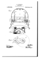
- Figure 1 is a vertic: a. locomotive sand box ments a pplicd theret vhich-I transverse section "of bowing my improve- !ig. 2 is an enlarged detail vertical sectiol oi? the casting,embody ing the commingli i chamber; air inlets, and discharge outlet; and Fig. 3 is a plan view of such eastintg.
- men-v tioned consists in arranging means for supj portingthe body of sandabove and immediately adjacent the point; where it is drawn from the heap and in the present case I have shown a. supportor bracket preferably in 6!, inlet 6 at the bottom of one end, preferably I -ot hood formation overhanging such inlet,
- an extensive semi-annular horizontal slot or opening is formed between the edge of the circular hooded end and the fioor of the sand box and such slot or opening can be of such a diminished height as to be less in width than the interior passageway and so prevent all possibility of large objects, such as pebbles, &c., that might be in the sand, en-
- an air and sand commingler device in the form of a single casting presentin a comminglin chamber, a sand inlet, a free air inlet distinct from the sand inlet, a passage the outer portion of which is adapted to receive a blast supply )ipe and the inner portion constituting a blast orifice, and a discharge outlet, with means for securing the device in place.
- an air and sand commingler device of hollow arch form having a base portion and terminating in a horizontal plane above the floor level so as to present a'hollow hooded portion the horizontal edge of which surrounds an inlet opening facing the floor of the sand box and communicating with the sand box through the space between such horizontal edge of the hooded portion and the floor of the box.
- a commingler device in the form of a single casting presenting bzise flanges for securin it in place and providing a conimingling e amber for sand and free air, an inlet for sand and a-free air orifice at one end, a discharge outlet and blast orifice at the opposite end, the
- blast orifice being located above and in line with the discharge outlet, and tapped nipple formations surrounding said orifices with which the free air and blast supply .mingler devices one located at each discharge outlet and presenting a commin ling chamber, a sand inlet, a free air inlet, a lastorifice, and a discharge outlet communicating with the sand box outlet, a free air stand pipe for each free air inlet, a main motive fluid supply and branch connections therefrom to the blast orifice of each of the commingler devices.
- a track sander the combination with a sand box and a commingler device having a hooded end portion with a sand inlet thereto facing the floor of the box: and communicating. with the box through the space between the edge of such hooded end por tion and the floor of the box,of a ledge or bracket located above said hooded end portion and projecting in a horizontal plane beyond the edge of same to support the body of sand above said ledge. 4
- a track sander the combination with a sand box, a commingler device having a sand inlet thereto and an air sup 1y con nected with said cominingler, of a at plate perforated to accommodate said supply pipe and resting on said commingler device to su port the sand above said inlet.
- a track sander In a track sander, the combination with a sand box, a commingler device having a sand inlet thereto and an air supply pipe connected with said colnmingler, of a disk centrally perforated to fit said supply pipe and resting on said comminglerdevice to support the sand above said inlet.
Landscapes
- Engineering & Computer Science (AREA)
- Transportation (AREA)
- Mechanical Engineering (AREA)
- Nozzles (AREA)
Description
S. S. UNDERWOOD.
TRACK SANDER.
APPLIOATIOH rum) JAN.11,1911.
1,000,055, Patanted Aug. 8, 1911.
'l'o all whom itmay concern.
Be it known that I, (bonny Salt-r11 Uxonnwo'on, "a citizen of the United States of America, residing in Montreal. Province of Quebec. Canada, have invented certain new and useful Improvements in 'lrack-Samlers; and 1' do hereby declare that the following is :rfull, clear, and exact description of the same. Y
My invention relates more particularly to track sanders ot the type shown in United States Patent No. 959596 in which a supply of free dry air mingled with the sand to facilitate expulsion of same from the sand box by the air blast. I
'llhe'prcsent .improvements comprise first arranging a simple casting presenting base flanges for securing it in place and, so as to be in closeoperative relation witl t fthe commingling chamber formed thereiyif. th'esand inlet thereto, the free air inlet,' tl blast oritice and the discharge outlet chan'iber and the relation being such blast. orifice is in immediate ,1 the sand and free air in the cl '1 real-"of the discharge outlet of such sand and free. airys rangement of means for supper the body of sand above the, point wherefit H s drawn from the heap on its way i the discharge outlet; an. third, the 'spe al (firm of the casting, which embodies e Fcdmmingling chamber with itsinlcts' an outlet; to facili- I tate its construction ant eady application to the' ordinary locomot sa-nd boxes at present iinllse;
For full comprehensidn, however of the: "t be had to the-ac invent-ion reference nu companying drawings i Figure 1 is a vertic: a. locomotive sand box ments a pplicd theret vhich-I transverse section "of bowing my improve- !ig. 2 is an enlarged detail vertical sectiol oi? the casting,embody ing the commingli i chamber; air inlets, and discharge outlet; and Fig. 3 is a plan view of such eastintg.
In applying m improvements to alocomotive sand box a of the well known form as shown in Fig. 1. I place my improved commingler device or casting so as to coininunicate with the discharge outlets b from the floor 1 of such box and dispose the compressed airor olast supply connections and free air supply referably as shown and hereafter describe t Y 5 The commingler device as stated com? Sb'ccificationuf Letters Patent.
to and electric can "fi te nsure? OFFICE TRACK-SANDER;
Patented Aug. 8, 1911} "'A' mtnkm filed January 11, 1911. Serial No. 602,061.
prises a single integral casting 2 preferably of arched tubular form with a base 3 pierced at 4 to allow of it's being readily secured in place by screw bolts 5, and presenting a. sand ciding with the axis ofthc disch'argeloutlet such orifice leading through a boss or nipple formatn'm 12 tapped to receive the airpressure or blast supply pipe 13.
In the present instance; where asgi beforc mentioned the device is shown as applied to the well known form ofjloeomotive sandbox a commingler device is arranged in .con'nec tion with each discharc end fits over and comnnnii'cates with the outletb-of the box and will be notedt tli iit the I blast orifice 11 of "the coinminglenis most advantageously arranged above and in vertical line with the coinciding axes. of the colmningler andsand box outlets and while :inrear of the outletis yet in advance of apd Y lll'ClUSU proxlnnty tothe comnfingled sand and free air with the decidedly improved resultthat thc'dried sand at the outset of its, c
t'avel issubjeeted to the maximum suction and propulsive effect of the blast.
The present application of my improvements shows of course two blast supply branch connections 13 leading from a common source 14', and independent free air supply pipes 9' with-slitted upper ends and regulating caps 16, but itj is obvious that such arrangement of free airand pressure supply connections may .be varied to suit different applications of the connningler devices.
A. further improvement as before men-v tioned consists in arranging means for supj portingthe body of sandabove and immediately adjacent the point; where it is drawn from the heap and in the present case I have shown a. supportor bracket preferably in 6!, inlet 6 at the bottom of one end, preferably I -ot hood formation overhanging such inlet,
I L foutltl of-thesand box the comnnnglerbei'ng =bolt ed to the floor i of the box in such positionifthat its-discharge y the form of a disk 17 centrally perforated to enable it to be fitted over the free air supply pipe and rest upon the boss 8 of the comlningler casting, so that it supports the body of sand above it and naturally avoids all chance of caking or blocking at the point where it is drawn from themain heap and discharged by the blast.
It is to be noted that by making the hooded sand inlet end as shown, an extensive semi-annular horizontal slot or opening is formed between the edge of the circular hooded end and the fioor of the sand box and such slot or opening can be of such a diminished height as to be less in width than the interior passageway and so prevent all possibility of large objects, such as pebbles, &c., that might be in the sand, en-
tering the interior or blocking any single restricted circular inlet such 'as found in most sanders.
I claim:
1. In a track sander, an air and sand commingler device in the form of a single casting presentin a comminglin chamber, a sand inlet, a free air inlet distinct from the sand inlet, a passage the outer portion of which is adapted to receive a blast supply )ipe and the inner portion constituting a blast orifice, and a discharge outlet, with means for securing the device in place.
'2. In a track sander, an air and sand commingler device of hollow arch form having a base portion and terminating in a horizontal plane above the floor level so as to present a'hollow hooded portion the horizontal edge of which surrounds an inlet opening facing the floor of the sand box and communicating with the sand box through the space between such horizontal edge of the hooded portion and the floor of the box.
3, In a track sander, a commingler device in the form of a single casting presenting bzise flanges for securin it in place and providing a conimingling e amber for sand and free air, an inlet for sand and a-free air orifice at one end, a discharge outlet and blast orifice at the opposite end, the
blast orifice being located above and in line with the discharge outlet, and tapped nipple formations surrounding said orifices with which the free air and blast supply .mingler devices one located at each discharge outlet and presenting a commin ling chamber, a sand inlet, a free air inlet, a lastorifice, and a discharge outlet communicating with the sand box outlet, a free air stand pipe for each free air inlet, a main motive fluid supply and branch connections therefrom to the blast orifice of each of the commingler devices.
5. In a track sander, the combination with a sand box and a commingler device having a hooded end portion with a sand inlet thereto facing the floor of the box: and communicating. with the box through the space between the edge of such hooded end por tion and the floor of the box,of a ledge or bracket located above said hooded end portion and projecting in a horizontal plane beyond the edge of same to support the body of sand above said ledge. 4
6. In a track sander, the combination with a sand box, a commingler device having a sand inlet thereto and an air sup 1y con nected with said cominingler, of a at plate perforated to accommodate said supply pipe and resting on said commingler device to su port the sand above said inlet.
In a track sander, the combination with a sand box, a commingler device having a sand inlet thereto and an air supply pipe connected with said colnmingler, of a disk centrally perforated to fit said supply pipe and resting on said comminglerdevice to support the sand above said inlet.
In testimony whereof, I have signed my' name to this specification, in the presence of two subscribing witnesses.
SIDNEY SMITH UNDERWOOI).
" Witnesses FRED J. SEARS, JOHN A. QKEEFE.
Priority Applications (1)
| Application Number | Priority Date | Filing Date | Title |
|---|---|---|---|
| US60206111A US1000055A (en) | 1911-01-11 | 1911-01-11 | Track-sander. |
Applications Claiming Priority (1)
| Application Number | Priority Date | Filing Date | Title |
|---|---|---|---|
| US60206111A US1000055A (en) | 1911-01-11 | 1911-01-11 | Track-sander. |
Publications (1)
| Publication Number | Publication Date |
|---|---|
| US1000055A true US1000055A (en) | 1911-08-08 |
Family
ID=3068382
Family Applications (1)
| Application Number | Title | Priority Date | Filing Date |
|---|---|---|---|
| US60206111A Expired - Lifetime US1000055A (en) | 1911-01-11 | 1911-01-11 | Track-sander. |
Country Status (1)
| Country | Link |
|---|---|
| US (1) | US1000055A (en) |
-
1911
- 1911-01-11 US US60206111A patent/US1000055A/en not_active Expired - Lifetime
Similar Documents
| Publication | Publication Date | Title |
|---|---|---|
| US1000055A (en) | Track-sander. | |
| US791397A (en) | Elbow-terminal for ventilation-piping. | |
| US968332A (en) | Air-treating machine. | |
| US914783A (en) | Sand-blast machine. | |
| US941457A (en) | Locomotive track-sander. | |
| US773909A (en) | Track-sander. | |
| US959596A (en) | Track-sander. | |
| US971481A (en) | Apparatus for cleaning gas. | |
| US824461A (en) | Track-sanding device. | |
| US1029284A (en) | Track-sander. | |
| US666718A (en) | Fountain-spittoon. | |
| US912167A (en) | Jet-condenser. | |
| US671651A (en) | Track-sanding apparatus for locomotives. | |
| US1527297A (en) | Felting machine | |
| US1019278A (en) | Steam-valve separator. | |
| US1234436A (en) | Sand-distributing device. | |
| US790933A (en) | Means for purifying air. | |
| US719395A (en) | Washer for sand-blast apparatus. | |
| US951207A (en) | Trap for sander devices. | |
| US1155910A (en) | Sanding device for locomotives. | |
| US1162107A (en) | Pulp-vat for paper-making machines. | |
| US507581A (en) | Franklin b | |
| US890310A (en) | Sanding apparatus for trolley-cars and the like. | |
| US942726A (en) | Track-sander. | |
| US914425A (en) | Track-sander. |