TWM651287U - Disc seat mechanism - Google Patents

Disc seat mechanism Download PDF

Info

Publication number
TWM651287U
TWM651287U TW112211703U TW112211703U TWM651287U TW M651287 U TWM651287 U TW M651287U TW 112211703 U TW112211703 U TW 112211703U TW 112211703 U TW112211703 U TW 112211703U TW M651287 U TWM651287 U TW M651287U
Authority
TW
Taiwan
Prior art keywords
knob
cover
hole
mounting
edge
Prior art date
Application number
TW112211703U
Other languages
Chinese (zh)
Inventor
鄭中仁
Original Assignee
金上吉塑膠股份有限公司
Priority date (The priority date is an assumption and is not a legal conclusion. Google has not performed a legal analysis and makes no representation as to the accuracy of the date listed.)
Filing date
Publication date
Application filed by 金上吉塑膠股份有限公司 filed Critical 金上吉塑膠股份有限公司
Priority to TW112211703U priority Critical patent/TWM651287U/en
Publication of TWM651287U publication Critical patent/TWM651287U/en

Links

Images

Landscapes

  • Vehicle Step Arrangements And Article Storage (AREA)

Abstract

一種盤座機構,包含一個盤體單元、一個安裝單元,以及一個復位單元。該盤體單元包括一個界定出一安裝孔的盤孔緣。該安裝單元包括一個由該盤孔緣往下延伸的安裝座、一個軸向上下且能相對安裝座轉動地插設在該安裝座中的旋鈕,以及一個設置在該旋鈕上的頂蓋。該旋鈕能被操作而鎖定或解鎖。鎖定時,該旋鈕撐頂該頂蓋,使該頂蓋無法往下移動並遮蓋住該安裝孔。解鎖時,該頂蓋低於該盤孔緣,該安裝孔露出。該復位單元連接於該安裝座與該旋鈕間,並能提供該旋鈕趨向鎖定的驅動力。本新型具有不操作時可自動鎖定的安全功效。A disk base mechanism includes a disk body unit, an installation unit, and a reset unit. The tray unit includes a tray hole rim defining a mounting hole. The mounting unit includes a mounting seat extending downward from the edge of the plate hole, a knob inserted into the mounting seat axially up and down and rotatable relative to the mounting seat, and a top cover disposed on the knob. The knob can be operated to lock or unlock. When locked, the knob supports the top cover so that the top cover cannot move downward and covers the installation hole. When unlocked, the top cover is lower than the edge of the plate hole, and the mounting hole is exposed. The reset unit is connected between the mounting base and the knob, and can provide a driving force for the knob to lock. This new model has the safety function of automatically locking when not in operation.

Description

盤座機構Tray mechanism

本新型是有關於一種嬰幼兒用品,特別是指一種學步車的盤座機構。The present invention relates to an infant product, in particular to a tray seat mechanism of a walker.

參閱圖1至3,申請人先前曾申請過一種如圖1至3所示的盤座機構,用以與其他元件/機構相配合構成一台適用於供一幼兒使用的學步車。Referring to Figures 1 to 3, the applicant has previously applied for a tray mechanism as shown in Figures 1 to 3, which is used in conjunction with other components/mechanisms to form a walker suitable for use by a young child.

該盤座機構包括一個盤體單元11,以及數個連接該盤體單元11的安裝單元12。該等安裝單元12適用於分別供數個物件13卡嵌設置。由於該等安裝單元12的結構彼此相同,且該等物件13的卡嵌結構彼此相同,故在下面的說明中將以其中一個的該安裝單元12與其中一個該物件13作為代表。The tray base mechanism includes a tray unit 11 and several mounting units 12 connected to the tray unit 11 . The installation units 12 are suitable for respectively mounting several objects 13 therein. Since the structures of the installation units 12 are the same as each other, and the engaging structures of the objects 13 are the same, one of the installation units 12 and one of the objects 13 will be used as representatives in the following description.

該安裝單元12包括一個一體由該盤體單元11往下延伸的安裝座14、一個插設在該安裝座14中的旋鈕15、一個設置在該旋鈕15中的彈簧16,以及一個設置在該彈簧16上的頂蓋17。The mounting unit 12 includes a mounting base 14 integrally extending downward from the tray unit 11 , a knob 15 inserted in the mounting base 14 , a spring 16 disposed in the knob 15 , and a spring 16 disposed in the knob 15 . Top cover 17 on spring 16.

該安裝座14形成有數個限位槽141。每一該限位槽141弧向延伸且側向開放。該等限位槽141可分別供該物件13的兩卡塊131(因對稱關係,圖1中僅示其一)卡入或脫離。The mounting base 14 is formed with a plurality of limiting grooves 141 . Each limiting groove 141 extends in an arc direction and is open laterally. The limiting grooves 141 can respectively allow the two blocking blocks 131 of the object 13 (due to the symmetry, only one is shown in FIG. 1 ) to be clipped in or out.

該旋鈕15包括一個撐抵在該安裝座14上的鈕環部151、一個由該鈕環部151往下延伸並往下突伸出該安裝座14的鈕體部152、一個由該鈕環部151往上延伸且環繞該彈簧16的環體部153,以及數個由該鈕環部151往上延伸且彼此弧向間隔排列在該環體部153外的突塊部154。每一該突塊部154頂端形成有一定位凸點155。The knob 15 includes a button ring portion 151 that is supported on the mounting base 14 , a button body portion 152 that extends downward from the button ring portion 151 and protrudes downward from the mounting base 14 , The ring portion 151 extends upward and surrounds the ring body portion 153 of the spring 16 , and a plurality of protruding block portions 154 extend upward from the button ring portion 151 and are arranged arcuately spaced apart from each other outside the ring body portion 153 . A positioning protrusion 155 is formed on the top of each protrusion 154 .

該頂蓋17包括一個橫向延伸且呈圓盤狀的蓋頂部171,以及一個由該蓋體部往下延伸且呈環狀的蓋底部172。該蓋底部172形成有數個形狀與該等突塊部154對應而能分別容納該等突塊部154的凹口173,以及數個定位缺口174。The top cover 17 includes a laterally extending and disk-shaped cover top 171 , and an annular cover bottom 172 extending downward from the cover body. The cover bottom 172 is formed with a plurality of notches 173 having shapes corresponding to the protruding portions 154 and capable of receiving the protruding portions 154 respectively, and a plurality of positioning notches 174 .

該旋鈕15的該鈕體部152可被一使用者以手轉動操作而鎖定或解鎖。鎖定時,該旋鈕15的該等突塊部154與該頂蓋17的該等凹口173錯位而為對準。該等突塊部154如圖3所示地相配合撐頂該蓋底部172,使得該頂蓋17無法相對該安裝座14被往下壓。此時,該頂蓋17遮蔽住該安裝座14的該等限位槽141。轉動該旋鈕15使該等突塊部154對準該等凹口173時可解鎖。解鎖時,該頂蓋17可相對該安裝座14被往下壓,該等限位槽141可以露出,從而允許對應的該物件13的該等卡塊131卡入。The knob body 152 of the knob 15 can be locked or unlocked by a user's manual rotation operation. When locked, the protrusions 154 of the knob 15 and the notches 173 of the top cover 17 are misaligned and aligned. As shown in FIG. 3 , the protrusions 154 cooperate to support the bottom 172 of the cover, so that the top cover 17 cannot be pressed down relative to the mounting base 14 . At this time, the top cover 17 covers the limiting grooves 141 of the mounting base 14 . The knob 15 can be unlocked by rotating the knob 15 to align the protrusions 154 with the notches 173 . When unlocked, the top cover 17 can be pressed down relative to the mounting base 14, and the limiting grooves 141 can be exposed, thereby allowing the corresponding blocking blocks 131 of the object 13 to be inserted.

此種盤座機構的美中不足之處在於,如若該物件13意外脫離該安裝座14,雖然該彈簧16能將該頂蓋17往上頂撐復位而封閉該安裝座14的內部空間,卻無法帶動該旋鈕15轉動重新鎖定。如此一來,該頂蓋17於幼兒拍打時將會上下移動,而有與該安裝座14相配合夾到幼兒手指的風險,有待改善。The shortcoming of this kind of plate base mechanism is that if the object 13 accidentally detaches from the mounting base 14, although the spring 16 can push the top cover 17 upward and reset it to close the internal space of the mounting base 14, it cannot move the object 13. The knob 15 is turned to re-lock. As a result, the top cover 17 will move up and down when the child pats it, and there is a risk of pinching the child's fingers when mating with the mounting base 14, which needs to be improved.

本新型的目的在於:改善先前技術的至少一個缺點。The object of the present invention is to improve at least one of the shortcomings of the prior art.

本新型盤座機構,包含一個盤體單元、一個安裝單元,以及一個復位單元。The new disk seat mechanism includes a disk body unit, an installation unit, and a reset unit.

該盤體單元包括一個界定出一安裝孔的盤孔緣。該安裝單元包括一個由該盤孔緣往下延伸的安裝座、一個軸向上下且能相對安裝座轉動地插設在該安裝座中的旋鈕,以及一個設置在該旋鈕上並遮蓋該安裝孔的頂蓋。該旋鈕能被操作而沿著彼此相反的一鎖定方向及一解鎖方向被轉動,而在一個鎖定位置與一個解鎖位置間變換。於該鎖定位置,該旋鈕撐頂該頂蓋,該頂蓋無法往下移動並遮蓋住該安裝孔。於該解鎖位置,該頂蓋低於該盤孔緣,且該安裝孔露出。該復位單元連接於該安裝座與該旋鈕間,能提供該旋鈕沿該鎖定方向移動以變換至該鎖定位置的驅動力。The tray unit includes a tray hole rim defining a mounting hole. The mounting unit includes a mounting seat extending downward from the edge of the plate hole, a knob inserted into the mounting seat axially up and down and rotatable relative to the mounting seat, and a knob disposed on the knob and covering the mounting hole. top cover. The knob can be operated to be rotated along a locking direction and an unlocking direction opposite to each other, so as to change between a locking position and an unlocking position. In the locked position, the knob supports the top cover, and the top cover cannot move downward and covers the installation hole. In the unlocked position, the top cover is lower than the edge of the plate hole, and the mounting hole is exposed. The reset unit is connected between the mounting base and the knob, and can provide a driving force for the knob to move along the locking direction to change to the locking position.

本新型的功效在於:該復位單元能提供該旋鈕變換至該鎖定位置的驅動力,在該旋鈕未被操作時能驅使該旋鈕變換至該鎖定位置,從而使得頂蓋無法往下移動,以維持遮蓋住該安裝孔的狀態,故本新型能產生不操作時可安全鎖定的效果,能降低夾住幼兒手指的風險。The function of the present invention is that the reset unit can provide the driving force for the knob to change to the locking position, and can drive the knob to change to the locking position when the knob is not operated, so that the top cover cannot move downward to maintain the function. The installation hole is covered, so the new model can produce a safe locking effect when not in operation, and can reduce the risk of pinching children's fingers.

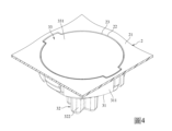
參閱圖4、5、6,本新型盤座機構的一個實施例,包含一個盤體單元2、一個連接該盤體單元2的安裝單元3,以及一個設置在該安裝單元3中的復位單元4。Referring to Figures 4, 5, and 6, an embodiment of the new tray mechanism includes a tray unit 2, a mounting unit 3 connected to the tray unit 2, and a reset unit 4 provided in the mounting unit 3. .

該盤體單元2的外形整體結構舉例來說可如先前技術圖1所示,但由於該盤體單元2的外形可以有多種變化,故在圖式中僅示意與本新型創作重點相關的部位。For example, the overall shape and structure of the tray unit 2 can be as shown in Figure 1 of the prior art. However, since the shape of the tray unit 2 can have many changes, only the parts related to the key points of the invention are shown in the drawing. .

該盤體單元2包括一個頂盤面21。該頂盤面21包括一個盤孔緣22。該盤孔緣22圍繞界定出一安裝孔23。在本新型的其他實施態樣中,該盤體單元2也可以包括數個的所述盤孔緣22,每一該盤孔緣22界定出各別的一個該安裝孔23。於此同時,該盤座機構即對應包括複數個的所述安裝單元3與複數個的所述復位單元4。The tray unit 2 includes a top tray 21 . The top disk surface 21 includes a disk hole rim 22 . The plate hole edge 22 defines a mounting hole 23 therearound. In other embodiments of the present invention, the tray unit 2 may also include a plurality of tray hole edges 22 , and each tray hole edge 22 defines a respective mounting hole 23 . At the same time, the base mechanism corresponds to a plurality of installation units 3 and a plurality of reset units 4 .

參閱圖5、6、7,該安裝單元3包括一個由該盤孔緣22往下延伸的安裝座31、一個軸向上下且能相對安裝座31轉動地插設在該安裝座31中的旋鈕32,以及一個設置在該旋鈕32上並遮蓋該安裝孔23的頂蓋33。Referring to Figures 5, 6, and 7, the mounting unit 3 includes a mounting seat 31 extending downward from the plate hole edge 22, and a knob inserted into the mounting seat 31 so as to be axially up and down and rotatable relative to the mounting seat 31. 32, and a top cover 33 provided on the knob 32 and covering the mounting hole 23.

該安裝座31包括一個呈圓環狀且由該盤孔緣22往下延伸的第一直環部311、一個呈圓環狀且由該第一直環部311的底端徑向往內延伸的橫環部312、一個呈圓環狀且由該橫環部312內側往下延伸的第二直環部313,以及一個呈圓環狀且由該第二直環部313的底端徑向往內延伸的支撐環部314。The mounting base 31 includes a circular ring-shaped first straight ring portion 311 extending downward from the plate hole edge 22 , and a circular ring-shaped first straight ring portion 311 extending radially inward from the bottom end of the first straight ring portion 311 . The transverse ring portion 312, a circular ring-shaped second straight ring portion 313 extending downward from the inside of the transverse ring portion 312, and a circular ring-shaped second straight ring portion 313 extending radially inward from the bottom end of the second straight ring portion 313. Extended support ring 314 .

該第一直環部311一體連接盤孔緣22,並界定出兩個徑向相對且上下延伸的直卡槽311a,以及兩個徑向相對且分別連通該等直卡槽311a的限位槽311b。每一該直卡槽311a的頂端連通該安裝孔23。每一該限位槽311b弧向延伸,其中一端連通各別的一個該直卡槽311a,另外一端則為封閉端。The first straight ring portion 311 is integrally connected to the disk hole edge 22 and defines two radially opposite straight slots 311a extending up and down, and two diametrically opposite limiting slots that are respectively connected to the straight slots 311a. 311b. The top end of each straight slot 311a communicates with the mounting hole 23 . Each limiting groove 311b extends in an arc direction, one end of which is connected to a respective straight blocking groove 311a, and the other end is a closed end.

該第二直環部313包括數個具有些許變形彈性而可用以供該旋鈕32卡設的卡鉤塊段313a,以及數個弧向間隔地位於該等卡鉤塊段313a旁的限位塊段313b。The second straight ring portion 313 includes a plurality of hook block segments 313a with a slight deformation elasticity that can be used for the knob 32 to be locked, and a plurality of limiting blocks located at arcuate intervals beside the hook block segments 313a. Paragraph 313b.

該旋鈕32包括一個呈圓環狀並撐抵在該安裝座31的該支撐環部314上的鈕環部321、一個由該鈕環部321往下突伸出該安裝座31的該支撐環部314的鈕體部322、一個由該鈕環部321徑向往外突伸且弧向延伸的限位部323、數個彼此弧向間隔且由該鈕環部321往上突伸的突塊部324,以及一個位於該等突塊部324內側而被該等突塊部324環繞的環體部325。The knob 32 includes a ring portion 321 that is annular and supports the support ring portion 314 of the mounting base 31 , and a support ring that protrudes downward from the button ring portion 321 out of the mounting base 31 . The button body part 322 of the part 314, a limiting part 323 that protrudes radially outward from the button ring part 321 and extends in an arc direction, and several protrusions that are arcuately spaced from each other and project upward from the button ring part 321. portion 324, and a ring body portion 325 located inside the protruding block portions 324 and surrounded by the protruding block portions 324.

該鈕體部322一體連接該鈕環部321,可供一使用者以手操作轉動而帶動該鈕環部321轉動,並帶動該等突塊部324移動。該限位部323位於該安裝座31其中兩個彼此弧向間隔的限位塊段313b間,被該等限位塊段313b限制移動幅度,進而限制該鈕環部321的轉動角度。The button body part 322 is integrally connected to the button ring part 321 and can be rotated by a user's hand to drive the button ring part 321 to rotate and drive the protruding block parts 324 to move. The limiting portion 323 is located between two limiting block segments 313b that are arcuately spaced from each other in the mounting base 31. The limiting block segments 313b limit the movement range, thereby limiting the rotation angle of the button ring portion 321.

每一該突塊部324包括一個間隔地位於該鈕環部321上方且沿著弧向方向橫向延伸的頂塊緣324a,以及一個由該頂塊緣324a往下傾斜延伸連接該鈕環部321的斜塊緣324b。每一該頂塊緣324a與每一該斜塊緣324b平順延伸無突起。Each protruding block portion 324 includes a top block edge 324a that is spaced above the button ring portion 321 and extends transversely along the arc direction, and a top block edge 324a that extends downward obliquely and connects to the button ring portion 321. The inclined block edge 324b. Each of the top block edges 324a and each of the inclined block edges 324b extend smoothly without protrusions.

該頂蓋33包括一個位於該安裝孔23中而遮蓋封閉住該安裝孔23的蓋頂部331,以及一個由該蓋頂部331的底面中央部位往下延伸並撐抵在該等突塊部324上的蓋底部332。The top cover 33 includes a cover top 331 located in the mounting hole 23 to cover and seal the mounting hole 23 , and a cover top 331 extending downward from the center of the bottom surface of the cover top 331 and supporting the protrusions 324 . The cover bottom 332.

該蓋底部332呈圓環狀,並形成有數個由底端往上凹且可分別對應容納該等突塊部324的凹口333。該等凹口333的形狀與該等突塊部324的形狀對應。The cover bottom 332 is annular, and is formed with a plurality of recesses 333 that are concave upward from the bottom end and can respectively accommodate the protrusions 324 . The shape of the notches 333 corresponds to the shape of the protrusions 324 .

該復位單元4包括一個一體由該鈕環部321往上延伸的第一鉤件41、一個一體由該支撐環部314往上延伸的第二鉤件42,以及一個勾設在該第一鉤件41與該第二鉤件42間的彈性件43。該第一鉤件41與該第二鉤件42弧向間隔。該彈性件43為一彈簧。The reset unit 4 includes a first hook 41 integrally extending upward from the button ring portion 321, a second hook 42 integrally extending upwardly from the support ring portion 314, and a hook hooked on the first hook. The elastic member 43 between the member 41 and the second hook member 42. The first hook member 41 and the second hook member 42 are arcuately spaced apart. The elastic member 43 is a spring.

該旋鈕32能被一使用者以手轉動操作而沿著彼此相反的一鎖定方向D11及一解鎖方向D12轉動,而在一個如圖4、6、7所示的鎖定位置與一個如圖8、9、10所示的解鎖位置間變換。The knob 32 can be rotated by a user's hand to rotate along a locking direction D11 and an unlocking direction D12 that are opposite to each other, and in a locking position as shown in Figures 4, 6 and 7 and in a locking position as shown in Figures 8 and 7. Changes between unlocking positions shown in 9 and 10.

參閱圖4、6、7,於該鎖定位置,該旋鈕32的該等突塊部324的該等頂塊緣324a,撐頂在該頂蓋33的該蓋底部332的底緣,且該等突塊部324與該蓋底部332的該等凹口333在弧向方向上錯位未對準,而無法分別卡入該等凹口333中。由於該頂蓋33的該蓋底部332被該等突塊部324所撐頂限位,因此該頂蓋33無法相對該旋鈕32及該安裝座31往下移動,而維持在如圖7所示的遮蓋住該安裝孔23的狀態,並與該頂盤面21等高、齊平。於此同時,該安裝座31的該等直卡槽311a與該等限位槽311b也被該頂蓋33的該蓋頂部331所遮蓋而未露出。Referring to Figures 4, 6, and 7, in the locked position, the top block edges 324a of the protruding block portions 324 of the knob 32 are supported against the bottom edge of the cover bottom 332 of the top cover 33, and the The protruding block 324 and the notches 333 of the cover bottom 332 are misaligned in the arc direction and cannot be respectively locked into the notches 333 . Since the cover bottom 332 of the top cover 33 is held up and limited by the protrusions 324, the top cover 33 cannot move downward relative to the knob 32 and the mounting base 31, and remains as shown in FIG. 7 The installation hole 23 is covered, and is at the same height and level as the top plate surface 21 . At the same time, the straight slots 311a and the limiting slots 311b of the mounting base 31 are also covered by the cover top 331 of the top cover 33 and are not exposed.

將該旋鈕32沿著圖6中的該解鎖方向D12轉動,可帶動該等突塊部324分別對準該頂蓋33的該蓋底部332的該等凹口333,並帶動位於該旋鈕32的該鈕環部321上的該第一鉤件41,沿著該解鎖方向D12遠離該第二鉤件42,從而拉長該彈性件43使該彈性件43儲存縮短的彈力,並使該旋鈕32變換至該解鎖位置。Rotating the knob 32 along the unlocking direction D12 in FIG. 6 can drive the protrusions 324 to be aligned with the notches 333 of the cover bottom 332 of the top cover 33 , and drive the knob 32 to rotate. The first hook 41 on the button ring portion 321 moves away from the second hook 42 along the unlocking direction D12, thereby elongating the elastic member 43 to store the shortened elastic force and causing the knob 32 to Transform to this unlocked position.

參閱圖8、9、10,於該解鎖位置,該等突塊部324卡入該等凹口333中,該頂蓋33的該蓋頂部331撐抵在該安裝座31的該橫環部312上,並低於該盤孔緣22及該安裝孔23,同時該蓋頂部331如圖8、10所示地不再遮蓋住該等直卡槽311a與該等限位槽311b,而允許本實施例適用於搭配使用的一物件9的兩卡塊91由該等直卡槽311a卡入並旋進該等限位槽311b中而被該安裝座31限位,進而卡嵌設置在該安裝座31上,同時卡抵該頂蓋33的該蓋頂部331,使該蓋頂部331維持在低於該盤孔緣22及該安裝孔23的狀態。Referring to Figures 8, 9, and 10, in the unlocking position, the protrusions 324 are inserted into the notches 333, and the top 331 of the top cover 33 is supported against the transverse ring portion 312 of the mounting base 31. above, and lower than the plate hole edge 22 and the mounting hole 23. At the same time, as shown in Figures 8 and 10, the cover top 331 no longer covers the straight slots 311a and the limiting slots 311b, allowing the The embodiment is suitable for two clamping blocks 91 of an object 9 to be used together. The two clamping blocks 91 are clamped into the straight slots 311a and screwed into the limiting slots 311b to be limited by the mounting base 31, and then are clamped and disposed in the installation. On the base 31 , the cover top 331 of the top cover 33 is engaged at the same time, so that the cover top 331 is maintained lower than the plate hole edge 22 and the mounting hole 23 .

由圖6、9的比較可以看出,當該旋鈕32處於該解鎖位置時,該復位單元4的該彈性件43,於圖9中的長度明顯大於圖6(旋鈕32處於鎖定位置)中的長度,因此該彈性件43儲存有由圖9回復至圖6的彈力。It can be seen from the comparison of Figures 6 and 9 that when the knob 32 is in the unlocking position, the length of the elastic member 43 of the reset unit 4 in Figure 9 is significantly longer than that in Figure 6 (when the knob 32 is in the locked position). length, so the elastic member 43 stores the elastic force to return from Figure 9 to Figure 6 .

於該解鎖位置下,如卡嵌在該安裝座31上的該物件9意外脫落,使得該頂蓋33不再受到該物件9的卡抵,此時即使該旋鈕32未被人工操作轉動以回復至該鎖定位置,該彈性件43也能因為趨向縮短而釋放彈力,帶動該旋鈕32沿該鎖定方向D11轉動而自動變換回復至該鎖定位置,使該頂蓋33受到該旋鈕32的該等突塊部324撐抵而無法往下移動,自動鎖定維持在該頂蓋33遮蓋住該盤孔緣22及該安裝孔23的鎖定狀態。由於該頂蓋33被鎖定無法往下移動,因此本實施例能降低該頂蓋33與該安裝座31相配合夾到幼兒手指的風險。In the unlocking position, if the object 9 embedded in the mounting base 31 accidentally falls off, so that the top cover 33 is no longer blocked by the object 9, even if the knob 32 is not manually turned to return When reaching the locking position, the elastic member 43 can also release elastic force due to the tendency to shorten, driving the knob 32 to rotate along the locking direction D11 and automatically return to the locking position, so that the top cover 33 is subject to the protrusions of the knob 32 . The block portion 324 resists and cannot move downward, and the automatic locking maintains the locked state in which the top cover 33 covers the plate hole edge 22 and the mounting hole 23 . Since the top cover 33 is locked and cannot move downward, this embodiment can reduce the risk of the child's fingers being pinched when the top cover 33 cooperates with the mounting base 31 .

參閱圖5、8、11,本實施例的第二個特點在於:一般正常使用時,當該物件9如圖11所示地卡入且使用者放開該旋鈕32後,該彈性件43也會釋放彈力帶動該旋鈕32沿該鎖定方向D11略微轉動,使得該頂蓋33略微上升,而以該蓋頂部331相配合與該安裝座31夾緊該物件9。也就是說,該復位單元4除了有可以自動鎖定的功效外,還能提高該物件9卡設於該安裝座31中的穩定度。Referring to Figures 5, 8, and 11, the second characteristic of this embodiment is that during normal use, when the object 9 is clicked in as shown in Figure 11 and the user releases the knob 32, the elastic member 43 also The elastic force is released to drive the knob 32 to rotate slightly in the locking direction D11, causing the top cover 33 to rise slightly, and the top 331 of the cover cooperates with the mounting base 31 to clamp the object 9. That is to say, in addition to the automatic locking function, the reset unit 4 can also improve the stability of the object 9 stuck in the mounting base 31 .

此外,每一該突塊部324的該頂塊緣324a與該斜塊緣324b平順延伸無突起,可利於該頂蓋33的該蓋底部332與該等突塊部324相對滑移移動,從而利於本實施例的該旋鈕32於該鎖定位置及該解鎖位置間變換。In addition, the top block edge 324a and the inclined block edge 324b of each protruding block portion 324 extend smoothly without protrusions, which can facilitate the relative sliding movement of the cover bottom 332 of the top cover 33 and the protruding block portions 324, thereby This embodiment is advantageous in that the knob 32 changes between the locked position and the unlocked position.

綜上所述,本新型盤座機構的功效在於:該復位單元4能提供該旋鈕32變換至該鎖定位置的驅動力,在該旋鈕32未被操作時驅使該旋鈕32變換至該鎖定位置,從而使得頂蓋33無法往下移動,以維持遮蓋住該安裝孔23的狀態,產生不操作時可安全鎖定的效果,具有能降低夾住幼兒手指的風險的功效。To sum up, the function of the new disk seat mechanism is that the reset unit 4 can provide the driving force for the knob 32 to change to the locking position, and drive the knob 32 to change to the locking position when the knob 32 is not operated. As a result, the top cover 33 cannot move downward to maintain the state of covering the installation hole 23, thereby producing a safe locking effect when not in operation, and has the effect of reducing the risk of pinching children's fingers.

以上所述者,僅為本新型的實施例而已,不能以此限定本新型的申請專利範圍,且依本新型申請專利範圍及專利說明書簡單等效變化與修飾之態樣,亦應為本新型申請專利範圍所涵蓋。The above are only examples of the present invention and cannot be used to limit the patentable scope of the present invention. Simple equivalent changes and modifications based on the patentable scope of the present invention and the patent specification should also be considered as the present invention. covered by the patent application.

2:盤體單元 21:頂盤面 22:盤孔緣 23:安裝孔 3:安裝單元 31:安裝座 311:第一直環部 311a:直卡槽 311b:限位槽 312:橫環部 313:第二直環部 313a:卡鉤塊段 313b:限位塊段 314:支撐環部 32:旋鈕 321:鈕環部 322:鈕體部 323:限位部 324:突塊部 324a:頂塊緣 324b:斜塊緣 325:環體部 33:頂蓋 331:蓋頂部 332:蓋底部 333:凹口 4:復位單元 41:第一鉤件 42:第二鉤件 43:彈性件 9:物件 91:卡塊 D11:鎖定方向 D12:解鎖方向 2: Disk unit 21:Top surface 22: Plate hole edge 23:Mounting holes 3: Installation unit 31:Mounting seat 311: First direct loop department 311a: Straight card slot 311b: Limit slot 312: Transverse ring part 313:Second straight ring part 313a: hook block section 313b: Limit block section 314: Support ring part 32: Knob 321: Button and ring part 322: Button body 323: Limiting part 324:Protruding part 324a: Top block edge 324b: inclined block edge 325: Ring body part 33:Top cover 331: Cover the top 332: cover bottom 333: Notch 4:Reset unit 41:First hook piece 42:Second hook piece 43: Elastic parts 9:Object 91: card block D11: Lock direction D12:Unlocking direction

本新型其他的特徵及功效,將於參照圖式的實施方式中清楚地呈現,其中: 圖1是一個立體圖,說明一個現有的盤座機構; 圖2是一個不完整的立體分解圖,說明該盤座機構; 圖3是一個不完整且局部剖切的剖視圖,說明該盤座機構; 圖4是一個不完整的立體圖,說明本新型盤座機構的一個實施例,且該實施例的一旋鈕處於一鎖定位置; 圖5是一個不完整的立體分解圖,說明該實施例; 圖6是一個不完整的剖視圖,視角由上往下,說明該實施例的該旋鈕處於該鎖定位置; 圖7是一個不完整的剖視圖,視角側向觀看,說明該實施例的該旋鈕處於該鎖定位置; 圖8是一個不完整且部分分解的立體分解圖,說明該實施例的該旋鈕處於一解鎖位置; 圖9是一個不完整的剖視圖,視角由上往下,說明該實施例的該旋鈕處於該解鎖位置; 圖10是一個不完整的剖視圖,視角側向觀看,說明該實施例的該旋鈕處於該解鎖位置;及 圖11是一個不完整的剖視圖,視角側向觀看,說明一物件卡設在本實施例中。 Other features and functions of the present invention will be clearly presented in the embodiments with reference to the drawings, in which: Figure 1 is a perspective view illustrating an existing tray mechanism; Figure 2 is an incomplete three-dimensional exploded view illustrating the plate seat mechanism; Figure 3 is an incomplete and partially cutaway cross-sectional view illustrating the disc seat mechanism; Figure 4 is an incomplete perspective view illustrating an embodiment of the new plate seat mechanism, and a knob of this embodiment is in a locked position; Figure 5 is an incomplete three-dimensional exploded view illustrating this embodiment; Figure 6 is an incomplete cross-sectional view, viewed from top to bottom, illustrating that the knob of this embodiment is in the locked position; Figure 7 is an incomplete cross-sectional view, viewed from the side, illustrating that the knob of this embodiment is in the locked position; Figure 8 is an incomplete and partially exploded three-dimensional exploded view, illustrating that the knob of this embodiment is in an unlocked position; Figure 9 is an incomplete cross-sectional view, viewed from top to bottom, illustrating that the knob of this embodiment is in the unlocking position; Figure 10 is an incomplete cross-sectional view, viewed from the side, illustrating that the knob of this embodiment is in the unlocking position; and Figure 11 is an incomplete cross-sectional view, viewed from the side, illustrating that an object is stuck in this embodiment.

2:盤體單元 2: Disk unit

21:頂盤面 21:Top surface

22:盤孔緣 22: Plate hole edge

23:安裝孔 23:Mounting holes

3:安裝單元 3: Installation unit

31:安裝座 31:Mounting seat

311:第一直環部 311: First direct loop department

311a:直卡槽 311a: Straight card slot

311b:限位槽 311b: Limit slot

312:橫環部 312: Transverse ring part

313:第二直環部 313:Second straight ring part

313a:卡鉤塊段 313a: hook block section

313b:限位塊段 313b: Limit block section

314:支撐環部 314: Support ring part

32:旋鈕 32: Knob

321:鈕環部 321: Button and ring part

322:鈕體部 322: Button body

323:限位部 323: Limiting part

324:突塊部 324:Protruding part

324a:頂塊緣 324a: Top block edge

324b:斜塊緣 324b: inclined block edge

325:環體部 325: Ring body part

33:頂蓋 33:Top cover

331:蓋頂部 331: Cover the top

332:蓋底部 332: cover bottom

333:凹口 333: Notch

4:復位單元 4:Reset unit

41:第一鉤件 41:First hook piece

42:第二鉤件 42:Second hook piece

43:彈性件 43: Elastic parts

D11:鎖定方向 D11: Lock direction

D12:解鎖方向 D12:Unlocking direction

Claims (5)

一種盤座機構,包含: 一個盤體單元,包括一個界定出一安裝孔的盤孔緣; 一個安裝單元,包括一個由該盤孔緣往下延伸的安裝座、一個軸向上下且能相對安裝座轉動地插設在該安裝座中的旋鈕,以及一個設置在該旋鈕上並遮蓋該安裝孔的頂蓋,該旋鈕能被操作而沿著彼此相反的一鎖定方向及一解鎖方向被轉動,而在一個鎖定位置與一個解鎖位置間變換,於該鎖定位置,該旋鈕撐頂該頂蓋,該頂蓋無法往下移動並遮蓋住該安裝孔,於該解鎖位置,該頂蓋低於該盤孔緣,且該安裝孔露出;及 一個復位單元,連接於該安裝座與該旋鈕間,能提供該旋鈕沿該鎖定方向移動以變換至該鎖定位置的驅動力。 A plate base mechanism includes: A plate unit includes a plate hole rim defining a mounting hole; A mounting unit includes a mounting base extending downward from the edge of the plate hole, a knob inserted into the mounting base axially up and down and rotatable relative to the mounting base, and a knob disposed on the knob and covering the mounting base. The top cover of the hole, the knob can be operated to be rotated along a locking direction and an unlocking direction opposite to each other, and changes between a locking position and an unlocking position, in the locking position, the knob supports the top cover , the top cover cannot move down and cover the installation hole. In the unlocking position, the top cover is lower than the edge of the plate hole, and the installation hole is exposed; and A reset unit is connected between the mounting base and the knob, and can provide a driving force for the knob to move along the locking direction to change to the locking position. 如請求項1所述的盤座機構,其中,該旋鈕包括數個彼此弧向間隔的突塊部,該頂蓋包括一個遮蓋住該安裝孔的蓋頂部,以及一個由該蓋頂部往下延伸並撐抵在該等突塊部上的蓋底部,該蓋底部形成有數個能分別對應容納該等突塊部的凹口,於該鎖定位置,該蓋底部被該等突塊部撐頂限位,該頂蓋無法相對該旋鈕往下移動,該蓋頂部遮蓋住該安裝孔,於該解鎖位置,該等突塊部分別卡入該等凹口。The disk base mechanism of claim 1, wherein the knob includes a plurality of protrusions spaced arcuately from each other, the top cover includes a cover top covering the mounting hole, and a cover extending downward from the cover top. And the bottom of the cover is supported on the protrusions. The bottom of the cover is formed with a plurality of notches that can respectively accommodate the protrusions. In the locking position, the bottom of the cover is supported by the protrusions. position, the top cover cannot move downward relative to the knob, and the top of the cover covers the installation hole. In the unlocking position, the protrusions are respectively locked into the notches. 如請求項2所述的盤座機構,其中,該旋鈕包括一個撐抵在該安裝座上的鈕環部、一個由該鈕環部往下突伸出該安裝座而適用於供一使用者轉動操作的鈕體部,該等突塊部由該鈕環部往上突伸。The disk base mechanism of claim 2, wherein the knob includes a button ring portion that is supported on the mounting base, and a button ring portion protrudes downward from the mounting base and is suitable for a user. The protrusions protrude upward from the button ring part of the button body part for rotation operation. 如請求項3所述的盤座機構,其中,每一該突塊部包括一個間隔地位於該鈕環部上方且沿著弧向方向橫向延伸的頂塊緣,以及一個由該頂塊緣往下傾斜延伸連接該鈕環部的斜塊緣,每一該頂塊緣與每一該斜塊緣平順延伸無突起。The tray seat mechanism according to claim 3, wherein each of the protruding block portions includes a top block edge that is spaced above the button ring portion and extends transversely along the arc direction, and a top block edge that extends from the top block edge to The edge of the inclined block extends downward and is connected to the button ring portion. Each edge of the top block and each edge of the inclined block extend smoothly without protrusions. 如請求項3所述的盤座機構,其中,該安裝座包括一個支撐該鈕環部且供該鈕體部插設的支撐環部,該復位單元包括一個設置在該鈕環部上的第一鉤件、一個設置在該支撐環部上的第二鉤件,以及一個勾設在該第一鉤件與該第二鉤件間的彈性件,該彈性件能恆提供驅動該旋鈕沿該鎖定方向移動以變換至該鎖定位置的彈力。The plate base mechanism according to claim 3, wherein the mounting base includes a support ring portion that supports the button ring portion and is used for the button body portion to be inserted, and the reset unit includes a third ring portion disposed on the button ring portion. A hook, a second hook disposed on the support ring, and an elastic member hooked between the first hook and the second hook. The elastic member can constantly drive the knob along the The elastic force that moves in the locking direction to change to the locking position.
TW112211703U 2023-10-30 2023-10-30 Disc seat mechanism TWM651287U (en)

Priority Applications (1)

Application Number Priority Date Filing Date Title
TW112211703U TWM651287U (en) 2023-10-30 2023-10-30 Disc seat mechanism

Applications Claiming Priority (1)

Application Number Priority Date Filing Date Title
TW112211703U TWM651287U (en) 2023-10-30 2023-10-30 Disc seat mechanism

Publications (1)

Publication Number Publication Date
TWM651287U true TWM651287U (en) 2024-02-01

Family

ID=90823281

Family Applications (1)

Application Number Title Priority Date Filing Date
TW112211703U TWM651287U (en) 2023-10-30 2023-10-30 Disc seat mechanism

Country Status (1)

Country Link
TW (1) TWM651287U (en)

Similar Documents

Publication Publication Date Title
US6170910B1 (en) Child support with canopy pivot and method of use
US9486111B2 (en) Bath safety rail
US6547068B2 (en) Single push-button type storage case for compact discs
EP0878653A2 (en) Child-resistant handle
US4117960A (en) Folding clothes-hanger
WO2012095823A1 (en) A fastener for fixing a mat to a carpet
TWM651287U (en) Disc seat mechanism
US6244779B1 (en) Angularly adjustable coupling
CN215538389U (en) Top toy
JPH0243179Y2 (en)
US4956900A (en) Fastening device
US6314589B1 (en) Toilet lid safety lock
JP3393330B2 (en) Belt connection fastener
US4742700A (en) Linearly operating side-locked padlock
JP3224954U (en) Lock assembly
CN109388176B (en) knob
CN209469123U (en) A door lock rotation self-locking opening structure
JPH0737588Y2 (en) Soft fitting device for undulating and rotating body of toilet bowl
JPS5915362Y2 (en) lighting equipment
JP4331366B2 (en) Stackable chairs
JPH0750573Y2 (en) Lock device
TWM677240U (en) Locking device
JPH0748924Y2 (en) Knob mounting structure with spring on the opening and closing body
CN222109449U (en) Hinged locking buckle and portable folding shoe clip
RU2806399C1 (en) Vacuum suction cup