TWI856445B - Assembly of electrical connectors - Google Patents
Assembly of electrical connectors Download PDFInfo
- Publication number
- TWI856445B TWI856445B TW111146651A TW111146651A TWI856445B TW I856445 B TWI856445 B TW I856445B TW 111146651 A TW111146651 A TW 111146651A TW 111146651 A TW111146651 A TW 111146651A TW I856445 B TWI856445 B TW I856445B
- Authority
- TW
- Taiwan
- Prior art keywords
- electrical connector
- rubber core
- connector assembly
- terminals
- circuit board
- Prior art date
Links
- 238000003032 molecular docking Methods 0.000 claims abstract description 30
- 239000002184 metal Substances 0.000 claims abstract description 26
- 238000006073 displacement reaction Methods 0.000 claims abstract description 8
- 230000005489 elastic deformation Effects 0.000 claims description 15
- 230000002787 reinforcement Effects 0.000 claims description 13
- 210000001503 joint Anatomy 0.000 claims description 12
- 230000008878 coupling Effects 0.000 claims description 5
- 238000010168 coupling process Methods 0.000 claims description 5
- 238000005859 coupling reaction Methods 0.000 claims description 5
- 230000013011 mating Effects 0.000 claims 3
- 230000000717 retained effect Effects 0.000 claims 1
- 238000003466 welding Methods 0.000 description 10
- 238000010586 diagram Methods 0.000 description 6
- 230000004308 accommodation Effects 0.000 description 5
- 230000000694 effects Effects 0.000 description 3
- 238000005516 engineering process Methods 0.000 description 3
- 238000009434 installation Methods 0.000 description 2
- 239000004973 liquid crystal related substance Substances 0.000 description 2
- 230000000712 assembly Effects 0.000 description 1
- 238000000429 assembly Methods 0.000 description 1
- 238000009792 diffusion process Methods 0.000 description 1
- 238000003780 insertion Methods 0.000 description 1
- 230000037431 insertion Effects 0.000 description 1
- 230000003014 reinforcing effect Effects 0.000 description 1
- 229910000679 solder Inorganic materials 0.000 description 1
- 238000006467 substitution reaction Methods 0.000 description 1
Images




Classifications
-
- H—ELECTRICITY
- H01—ELECTRIC ELEMENTS
- H01R—ELECTRICALLY-CONDUCTIVE CONNECTIONS; STRUCTURAL ASSOCIATIONS OF A PLURALITY OF MUTUALLY-INSULATED ELECTRICAL CONNECTING ELEMENTS; COUPLING DEVICES; CURRENT COLLECTORS
- H01R12/00—Structural associations of a plurality of mutually-insulated electrical connecting elements, specially adapted for printed circuits, e.g. printed circuit boards [PCB], flat or ribbon cables, or like generally planar structures, e.g. terminal strips, terminal blocks; Coupling devices specially adapted for printed circuits, flat or ribbon cables, or like generally planar structures; Terminals specially adapted for contact with, or insertion into, printed circuits, flat or ribbon cables, or like generally planar structures
- H01R12/70—Coupling devices
- H01R12/91—Coupling devices allowing relative movement between coupling parts, e.g. floating or self aligning
-
- H—ELECTRICITY
- H01—ELECTRIC ELEMENTS
- H01R—ELECTRICALLY-CONDUCTIVE CONNECTIONS; STRUCTURAL ASSOCIATIONS OF A PLURALITY OF MUTUALLY-INSULATED ELECTRICAL CONNECTING ELEMENTS; COUPLING DEVICES; CURRENT COLLECTORS
- H01R12/00—Structural associations of a plurality of mutually-insulated electrical connecting elements, specially adapted for printed circuits, e.g. printed circuit boards [PCB], flat or ribbon cables, or like generally planar structures, e.g. terminal strips, terminal blocks; Coupling devices specially adapted for printed circuits, flat or ribbon cables, or like generally planar structures; Terminals specially adapted for contact with, or insertion into, printed circuits, flat or ribbon cables, or like generally planar structures
- H01R12/70—Coupling devices
- H01R12/71—Coupling devices for rigid printing circuits or like structures
-
- H—ELECTRICITY
- H01—ELECTRIC ELEMENTS
- H01R—ELECTRICALLY-CONDUCTIVE CONNECTIONS; STRUCTURAL ASSOCIATIONS OF A PLURALITY OF MUTUALLY-INSULATED ELECTRICAL CONNECTING ELEMENTS; COUPLING DEVICES; CURRENT COLLECTORS
- H01R24/00—Two-part coupling devices, or either of their cooperating parts, characterised by their overall structure
Landscapes
- Coupling Device And Connection With Printed Circuit (AREA)
- Details Of Connecting Devices For Male And Female Coupling (AREA)
Abstract
Description
本發明係有關於一種電連接器的技術領域,特別是有關於一種電性連接兩個電路板且在與電路板垂直的方向上可移動地對接以調整兩個電路板的相對位置的電連接器組合。 The present invention relates to the technical field of an electrical connector, and in particular to an electrical connector assembly that electrically connects two circuit boards and can be movably connected in a direction perpendicular to the circuit boards to adjust the relative positions of the two circuit boards.
液晶螢幕包括液晶顯示面板與背光模組,背光模組發出光線穿過液晶顯示面板產生影像。現有的背光模組是以發光二極體作為光源,因此需要電源模組對發光二極體進行供電。現有的電源模組與發光二極體是分別設置在兩個電路板上,因此需要電連接器組合來電性連接兩個電路板,以便達成對背光模組的供電。 The LCD screen includes a liquid crystal display panel and a backlight module. The backlight module emits light that passes through the liquid crystal display panel to produce an image. The existing backlight module uses a light-emitting diode as a light source, so a power module is required to supply power to the light-emitting diode. The existing power module and the light-emitting diode are respectively arranged on two circuit boards, so an electrical connector assembly is required to electrically connect the two circuit boards in order to achieve power supply to the backlight module.
現有的液晶螢幕由於薄型化的要求,因此殼體內的容置空間的高度很小。如何在非常侷限的容置空間內設計出能夠電性連接兩個電路板的電連接器組合而且使兩個電路板保持在相同高度以保持背光模組的擴散膜片安裝後的平整度是目前重要的課題。 Due to the requirement of thinness, the height of the housing space of existing LCD screens is very small. How to design an electrical connector assembly that can electrically connect two circuit boards in a very limited housing space and keep the two circuit boards at the same height to maintain the flatness of the diffusion film of the backlight module after installation is an important issue at present.
本發明的目的在於提供一種電連接器組合,公端電連接器與母端電連接器在與電路板垂直的方向上可移動地對接,以便在組裝時能夠調整兩個電路板的相對位置,而使得兩個電路板於垂直方向保持在預定的相對位置,而利於其他部件的組裝。同時公端電連接器與母端電連接器的對接處在與電路板平行的方向上產生浮動位移,以便補償水平方向組裝的公差。 The purpose of the present invention is to provide an electrical connector assembly, in which the male electrical connector and the female electrical connector are movably connected in a direction perpendicular to the circuit board, so that the relative position of the two circuit boards can be adjusted during assembly, so that the two circuit boards are kept in a predetermined relative position in the vertical direction, which is conducive to the assembly of other components. At the same time, the joint between the male electrical connector and the female electrical connector produces a floating displacement in a direction parallel to the circuit board to compensate for the tolerance of horizontal assembly.
本發明的電連接器組合的一實施例包括一公端電連接器及一母端電連接器。公端電連接器包括一第一膠芯、複數個第一端子及一金屬殼件。第一膠芯設置於第一電路板,第一膠芯具有一對接凹部。複數個第一端子成列地設置於第一膠芯,每個第一端子的一端延伸至對接凹部內。金屬殼件設置於第一膠芯,金屬殼件包括一止擋部。止擋部跨設於對接凹部。母端電連接器包括一第二膠芯、一第三膠芯及多個第二端子。第二膠芯設置於第二電路板。多個第二端子一端對應地固定於第二端子槽。第三膠芯由第二端子支持而可移動地設置於第二膠芯內,而可於與第一電路板和第二電路板平行的一第一方向上產生一第一浮動位移且於一第二方向上產生一第二浮動位移,第一方向垂直於第二方向,第三膠芯包括一對接端部及一止擋凸部,對接端部延伸突出於第二膠芯。複數個第二端子的一端從對接端部露出,止擋凸部設置於對接端部且沿一第三方向凸起,第三方向垂直於第一方向及第二方向。其中公端電連接器的對接凹部沿第三方向與母端電連接器的止擋凸部可移動地對接而於第一方向上形成限位,且第三膠芯的止擋凸部位於對接凹部與止擋部之間且抵接於止擋部,使得於第二方向上形成限位,且第一端子對應地接觸於第二端子。 An embodiment of the electrical connector assembly of the present invention includes a male electrical connector and a female electrical connector. The male electrical connector includes a first rubber core, a plurality of first terminals and a metal shell. The first rubber core is arranged on the first circuit board, and the first rubber core has a docking recess. A plurality of first terminals are arranged in a row on the first rubber core, and one end of each first terminal extends into the docking recess. The metal shell is arranged on the first rubber core, and the metal shell includes a stopper. The stopper is arranged across the docking recess. The female electrical connector includes a second rubber core, a third rubber core and a plurality of second terminals. The second rubber core is arranged on the second circuit board. One end of a plurality of second terminals is correspondingly fixed to the second terminal slot. The third rubber core is supported by the second terminal and is movably disposed in the second rubber core, and can generate a first floating displacement in a first direction parallel to the first circuit board and the second circuit board and a second floating displacement in a second direction, the first direction is perpendicular to the second direction, and the third rubber core includes a butt joint end and a stop convex portion, and the butt joint end extends out of the second rubber core. One end of a plurality of second terminals is exposed from the butt joint end, and the stop convex portion is disposed at the butt joint end and protrudes along a third direction, and the third direction is perpendicular to the first direction and the second direction. The butt joint recess of the male end electrical connector is movably butt jointed with the stop convex portion of the female end electrical connector along the third direction to form a limit in the first direction, and the stop convex portion of the third rubber core is located between the butt joint recess and the stop convex portion and abuts against the stop convex portion, so that a limit is formed in the second direction, and the first terminal correspondingly contacts the second terminal.
本發明的電連接器組合藉由在公端電連接器的第一膠芯設置對接凹部,在母端電連接器的第三膠芯設置對接端部及位於對接端部的止擋凸部,母端電連接器的對接端部與公端電連接器的對接凹部在與兩個電路板垂直的第三方向上可移動地對接,而調整第一電路板與第二電路板的相對位置,以配合其他部件的組裝。同時母端電連接器的第三膠芯可於第一方向及第二方向移動地設置第二膠芯內,使得公端電連接器與母端電連接器對接時,可以補償兩個電路板組裝的公差。 The electrical connector assembly of the present invention is provided with a docking recess on the first rubber core of the male electrical connector, and a docking end and a stop convex portion located at the docking end are provided on the third rubber core of the female electrical connector. The docking end of the female electrical connector and the docking recess of the male electrical connector can be movably docked in a third direction perpendicular to the two circuit boards, thereby adjusting the relative positions of the first circuit board and the second circuit board to match the assembly of other components. At the same time, the third rubber core of the female electrical connector can be movably arranged in the second rubber core in the first direction and the second direction, so that when the male electrical connector and the female electrical connector are docked, the tolerance of the assembly of the two circuit boards can be compensated.
為充分瞭解本發明之目的、特徵及功效,茲藉由下述具體之實施例,並配合所附之圖式,對本發明做一詳細說明,說明如後。 In order to fully understand the purpose, features and effects of the present invention, the present invention is described in detail through the following specific embodiments and the attached drawings. The description is as follows.
於本發明中,係使用「一」或「一個」來描述本文所述的單元、元件和組件。此舉只是為了方便說明,並且對本發明之範疇提供一般性的意義。因此,除非很明顯地另指他意,否則此種描述應理解為包括一個、至少一個,且單數也同時包括複數。 In the present invention, "one" or "an" is used to describe the units, components and assemblies described herein. This is only for the convenience of explanation and to provide a general meaning for the scope of the present invention. Therefore, unless it is obvious that it is otherwise intended, such description should be understood to include one, at least one, and the singular also includes the plural.
於本發明中,用語「包含」、「包括」、「具有」、「含有」或其他任何類似用語意欲涵蓋非排他性的包括物。舉例而言,含有複數要件的一元件、結構、製品或裝置不僅限於本文所列出的此等要件而已,而是可以包括未明確列出但卻是該元件、結構、製品或裝置通常固有的其他要件。除此之外,除非有相反的明確說明,用語「或」是指涵括性的「或」,而不是指排他性的「或」。 In the present invention, the terms "include", "including", "have", "contain" or any other similar terms are intended to cover non-exclusive inclusions. For example, a component, structure, product or device containing multiple elements is not limited to the elements listed herein, but may include other elements that are not explicitly listed but are generally inherent to the component, structure, product or device. In addition, unless expressly stated to the contrary, the term "or" refers to an inclusive "or" rather than an exclusive "or".
請參閱圖1、圖2、圖3,其中圖1是本發明的電連接器組合的一實施例的立體圖,圖2是圖1的電連接器組合的立體分解圖,圖3是圖2的電連接器組合的另一視角的立體分解圖。如圖所示,本實施例的電連接器組合1係用於電性連接一第一電路板P1以及一第二電路板P2,第一電路板P1可以是例如設置光源的電路板,第二電路板P2可以是設置電源模組的電路板,藉由電連接器組合1使第一電路板P1與第二電路板P2電性連接,使得電源模組經由電連接器組合1供電於光源。
Please refer to Figures 1, 2 and 3, wherein Figure 1 is a three-dimensional diagram of an embodiment of the electrical connector assembly of the present invention, Figure 2 is a three-dimensional exploded diagram of the electrical connector assembly of Figure 1, and Figure 3 is a three-dimensional exploded diagram of the electrical connector assembly of Figure 2 from another viewing angle. As shown in the figure, the
本實施例的電連接器組合1包括一公端電連接器10以及一母端電連接器20。公端電連接器10設置於第一電路板P1,母端電連接器20設置於第二電路板P2,藉由公端電連接器10與母端電連接器20對接,使第一電路板P1與第二電路板P2形成電性連接。
The
請參閱圖4及圖5,其中圖4是本發明的電連接器組合的公端電連接器的立體分解圖,圖5是圖4的公端電連接器的另一視角的立體分解圖。公端電連接器10包括一第一膠芯11、多個第一端子12以及一金屬殼件13。第一膠芯11設置於第一電路板P1。第一膠芯11呈長方體,其長邊一側的邊緣形成一對接凹部111,與對接凹部111相對的另一側具有一突緣112,在突緣112的邊緣形成端子讓槽113,第一膠芯11的側面與突緣112的底面抵接承靠於第一電路板P1。
Please refer to Figures 4 and 5, wherein Figure 4 is a three-dimensional exploded view of the male end electrical connector of the electrical connector assembly of the present invention, and Figure 5 is a three-dimensional exploded view of the male end electrical connector of Figure 4 from another viewing angle. The male end
對接凹部111是由兩個於一第一方向L1上相對設置的限位壁1111以及與兩個限位壁1111相鄰且與一第一方向L1平行的一第一對接壁1112構成。第一膠芯11包括多個第一端子槽114,多個第一端子槽114沿第一方向L1排成一列,每個第一端子槽114沿一第二方向L2延伸且開口於第一膠芯11的底部、設有突緣112側面和突緣112的端子讓槽113的槽壁,且每個第一端子槽114具有設置於第一對接壁1112的一第一開口1141。
The
每個第一端子12包括一彈性接觸部121、一彈性變形部122、一第一固持部123及一第一焊接部124。每個第一端子12對應地設置於一個第一端子槽114中。第一固持部123插置於與每個第一端子槽114連通的固持定位槽115而固定於第一膠芯11,彈性接觸部121位於第一端子12的一端而且從第一對接壁1112的第一開口1141突出,彈性變形部122連接於彈性
接觸部121供第一端子12於第二方向L2上產生彈性形變。第一焊接部124從端子讓槽113的槽壁突出,而且以表面安裝技術(SMT)焊接於第一電路板P1的焊墊。
Each
金屬殼件13包括一止擋部131、一結構強化部132以及兩個定位部133。止擋部131與結構強化部132為相鄰且彼此垂直設置的條狀體,而且止擋部131與結構強化部132都沿第一方向L1延伸。其中止擋部131與一第二方向L2垂直,結構強化部132與第二方向L2平行,第二方向L2與第一方向L1垂直。兩個定位部133分別設置在止擋部131與結構強化部132的相對兩側且包覆第一膠芯11的兩個短側邊。金屬殼件13可以強化第一膠芯11的結構而且對第一端子12產生電磁屏蔽的效果。
The
金屬殼件13藉由定位部133的定位孔1331與第一膠芯11的上表面和下表面的突起116結合而在第一方向L1和第二方向L2產生限位,金屬殼件13藉由沿第一方向L1延伸的插片1332插置於第一膠芯11的插槽117而在一第三方向L3上產生限位,第三方向L3垂直於第一方向L1和第二方向L2。如此金屬殼件13與第一膠芯11結合而且在第一方向L1、第二方向L2和第三方向L3都產生限位而定位於第一膠芯11,使得金屬殼件13與第一膠芯11形成一體化的結構。金屬殼件13藉由定位部133的焊接片1333焊接於第一電路板P,同時藉此使第一膠芯11定位在第一電路板P1上。
The
請參閱圖6和圖7,其中圖6是本發明的電連接器組合的母端電連接器的立體分解圖,圖7是圖6的母端電連接器的另一視角的立體分解圖。母端電連接器20包括一金屬殼件21、一第二膠芯22、一第三膠芯23以及多個第二端子24。母端電連接器20設置於第二電路板P2。
Please refer to Figures 6 and 7, wherein Figure 6 is a three-dimensional exploded view of the female end electrical connector of the electrical connector assembly of the present invention, and Figure 7 is a three-dimensional exploded view of the female end electrical connector of Figure 6 from another perspective. The female end
金屬殼件21設置於第二膠芯22。金屬殼件21包括結構強化部211和連接於結構強化部211相對兩側的兩個安裝部212。結構強化部211覆蓋於第二膠芯22的上表面,對第二膠芯22產生強化結構的效果,同時對設置於第二膠芯22的第二端子24產生電磁屏蔽的效果。
The
安裝部212藉由卡合片2121卡合於第二膠芯22的卡合凹部22a而在第一方向L1與第二方向L2產生限位,同時藉由沿第一方向L1延伸的插片2122插置於第二膠芯22的插槽22b而在第三方向L3上產生限位,藉此金屬殼件21與第二膠芯22形成一體化的結構,而且金屬殼件21藉由安裝部212的焊接片2123焊接於第二電路板P2。
The mounting
第二膠芯22為長方體的結構,其在底部和一側形成一凹陷的容置空間221,第二膠芯22還包括複數個第二端子槽222,其成列地設置於構成容置空間221的一後壁而且形成與容置空間221連通的狀態。
The
第三膠芯23為中空的框架狀,其包括一對接端部231、設置於對接端部231且沿第三方向L3突起的止擋凸部232以及與對接端部231相對設置的結合端部233。對接端部231的一側具有一第二對接面231a,第三膠芯23在對接端部231的第二對接面231a設有第三端子槽234而且在對接端部231的底面設有定位槽235。止擋凸部232靠近第二膠芯22的一側設有一止擋面232a。
The
每個第二端子24包括一第二固持部241、一第三固持部242、一第二彈性變形部243以及一第二焊接部244。第二固持部241固設於第二膠芯22的第二端子槽222,第三固持部242固設於第三膠芯23的第三端子槽234,藉此第二端子24藉由其剛性支持第三膠芯23。第三膠芯23的結合端部
233設置於第二膠芯22的容置空間221而且與容置空間221的壁面在第一方向L1與第二方向L2上具有既定的間距,藉由第二端子24的彈性變形使得第二端子24支持的第三膠芯23能夠在第一方向L1與第二方向L2上產生浮動位移。第二彈性變形部243連接第二固持部241與第三固持部242,且第二彈性變形部243位於容置空間221內,第二膠芯22具有一容置凹部223,容置凹部223設置於容置空間221的頂壁,第二端子24的第二彈性變形部243的頂端容置於容置凹部223。第二焊接部244從第二膠芯22的後端突出,且以表面安裝技術焊接於第二電路板P2上。
Each
請參閱圖8、圖9、圖10及圖11,其中圖8為本發明的電連接器組合的公端電連接器與母端電連接器組裝前的側視圖。圖9為本發明的電連接器組合的公端電連接器與母端電連接器組裝後的側視圖。圖10為本發明的電連接器組合的俯視圖。圖11為圖10的沿A-A線的剖視圖。當公端連接器10沿著第三方向L3與母端連接器20對接時,公端連接器10的第一膠芯11的對接凹部111沿第三方向L3與母端電連接器20的止擋凸部232可移動地對接,藉由對接凹部111於第一方向L1上的的兩個限位壁1111抵接於止擋凸部232兩側而於第一方向L1上形成限位。同時第三膠芯23的止擋凸部232位於對接凹部111與金屬殼件13的止擋部131之間且止擋凸部232的止擋面232a抵接於止擋部而於第二方向L2形成限位。
Please refer to Figures 8, 9, 10 and 11, wherein Figure 8 is a side view of the male end electrical connector and the female end electrical connector of the electrical connector assembly of the present invention before assembly. Figure 9 is a side view of the male end electrical connector and the female end electrical connector of the electrical connector assembly of the present invention after assembly. Figure 10 is a top view of the electrical connector assembly of the present invention. Figure 11 is a cross-sectional view along line A-A of Figure 10. When the
對接凹部111的第一對接壁1112與對接端部231的第二對接面231a相對,第一端子12的彈性接觸部121對應地接觸於第二端子24的第三固持部242的表面。由於第三固持部242是沿第三方向L3延伸,因此第一端子12的彈性接觸部121與第二端子24的第三固持部242在第三方向L3上
產生一接觸範圍,彈性接觸部121與第三固持部242在接觸範圍內都保持接觸,使得公端連接器10沿著第三方向L3與母端連接器20對接時,即使調整第一電路板P1與第二電路板P2的相對位置,公端連接器10與母端連接器20仍然可以在上述接觸範圍保持電性連接,而提供第一電路板P1與第二電路板P2位置上的調整彈性。
The first
由於母端連接器20的第三膠芯23能夠在第一方向L1與第二方向L2上產生浮動位移,因此公端連接器10與母端連接器20對接時,能夠在第一方向L1和第二方向L2上補償第一電路板P1與第二電路板P2組裝的公差。
Since the
請參閱圖12與圖13,其中圖12為本發明的電連接器組合的又另一視角的立體圖,圖13為本發明的電連接器組合的又另一視角的立體圖。第三膠芯23更包括於第二方向L2上設置於止擋凸部232的相對兩側且沿第一方向L1延伸的兩個第一導引斜面2321,第一膠芯11包括設於對接凹部111的底部邊緣於第二方向L2且沿第一方向L1的一第二導引斜面1113,金屬外殼13更包括設置於止擋部131的底緣於第二方向L2且沿第一方向L1延伸的一第三導引斜面1311,當公端電連接器10與母端電連接器20對接時,兩個第一導引斜面2321分別對應於第二導引斜面1113與第三導引斜面1311,用於輔助公端電連接器10與母端電連接器20對接。
Please refer to FIG. 12 and FIG. 13 , wherein FIG. 12 is a three-dimensional view of the electrical connector assembly of the present invention from yet another viewing angle, and FIG. 13 is a three-dimensional view of the electrical connector assembly of the present invention from yet another viewing angle. The
第三膠芯23更包括於第一方向L1上設置於止擋凸部232的相對兩側的兩個第四導引斜面2322,第二膠芯22更包括於第一方向L1上設置於對接凹部111的底部邊緣相對兩側的兩個第五導引斜面1114,當公端電
連接器10與母端電連接器20對接時,兩個第四導引斜面2322對應於第五導引斜面1114,用於輔助公端電連接器10與母端電連接器20對接。
The
本發明在上文中已以較佳實施例揭露,然熟習本項技術者應理解的是,實施例僅用於描繪本發明,而不應解讀為限制本發明之範圍。應注意的是,舉凡與實施例等效之變化與置換,均應設為涵蓋於本發明之範疇內。因此,本發明之保護範圍當以申請專利範圍所界定者為準。 The present invention has been disclosed in the above text with preferred embodiments, but those familiar with the present technology should understand that the embodiments are only used to describe the present invention and should not be interpreted as limiting the scope of the present invention. It should be noted that all changes and substitutions equivalent to the embodiments should be included in the scope of the present invention. Therefore, the scope of protection of the present invention shall be based on the scope defined by the patent application.
1:電連接器組合 1:Electrical connector assembly
10:公端電連接器 10: Male electrical connector
11:第一膠芯 11: First rubber core
12:第一端子 12: First terminal
13:金屬殼件 13:Metal shell
20:母端電連接器 20: Female electrical connector
21:金屬殼件 21:Metal shell
22:第二膠芯 22: Second rubber core
22a:卡合凹部 22a: Engagement recess
22b:插槽 22b: Slot
23:第三膠芯 23: The third rubber core
24:第二端子 24: Second terminal
111:對接凹部 111: Docking recess
112:突緣 112: Sudden Edge
113:端子讓槽 113: Terminal slot
116:突起 116: protrusion
117:插槽 117: Slot
121:彈性接觸部 121: Elastic contact part
122:彈性變形部 122: Elastic deformation part
123:第一固持部 123: First holding part
124:第一焊接部 124: First welding section
131:止擋部 131: Stopper
132:結構強化部 132: Structural reinforcement section
133:定位部 133: Positioning unit
211:結構強化部 211: Structural reinforcement section
212:安裝部 212: Installation Department
221:容置空間 221: Storage space
222:第二端子槽 222: Second terminal slot
223:容置凹部 223: Accommodating recess
231:對接端部 231: Butt end
232:止擋凸部 232: Stop convex part
232a:止擋面 232a: Stop surface
233:結合端部 233: Binding end
241:第二固持部 241: Second holding part
242:第三固持部 242: Third holding part
243:第二彈性變形部 243: Second elastic deformation part
244:第二焊接部 244: Second welding section
1111:限位壁 1111: Limiting wall
1112:第一對接壁 1112: First abutting wall
1113:第二導引斜面 1113: Second guiding slope
1114:第五導引斜面 1114: The fifth guiding slope
1141:第一開口 1141: First opening
1311:第三導引斜面 1311: The third guide slope
1331:定位孔 1331: Positioning hole
1332:插片 1332: Insert
1333:焊接片 1333: Welding sheet
2121:卡合片 2121: snap-fit piece
2122:插片 2122: Insert
2123:焊接片 2123: Welding sheet
2321:第一導引斜面 2321: First guide slope
2322:第四導引斜面 2322: The fourth guiding slope
P1:第一電路板 P1: First circuit board
P2:第二電路板 P2: Second circuit board
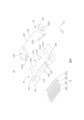
圖1是本發明的電連接器組合的一實施例的立體圖。 Figure 1 is a three-dimensional diagram of an embodiment of the electrical connector assembly of the present invention.
圖2是圖1的電連接器組合的立體分解圖。 Figure 2 is a three-dimensional exploded view of the electrical connector assembly of Figure 1.
圖3是圖2的電連接器組合的另一視角的立體分解圖。 FIG. 3 is a three-dimensional exploded view of the electrical connector assembly of FIG. 2 from another perspective.
圖4是本發明的電連接器組合的公端電連接器的立體分解圖。 Figure 4 is a three-dimensional exploded view of the male end electrical connector of the electrical connector assembly of the present invention.
圖5是圖4的公端電連接器的另一視角的立體分解圖。 FIG. 5 is a three-dimensional exploded view of the male end electrical connector of FIG. 4 from another perspective.
圖6是本發明的電連接器組合的母端電連接器的立體分解圖。 Figure 6 is a three-dimensional exploded view of the female end electrical connector of the electrical connector assembly of the present invention.
圖7是圖6的母端電連接器的另一視角的立體分解圖。 FIG. 7 is a three-dimensional exploded view of the female electrical connector of FIG. 6 from another perspective.
圖8是本發明的電連接器組合的公端電連接器與母端電連接器組裝前的側視圖。 Figure 8 is a side view of the male end electrical connector and the female end electrical connector of the electrical connector assembly of the present invention before assembly.
圖9為本發明的電連接器組合的公端電連接器與母端電連接器組裝後的側視圖。 Figure 9 is a side view of the assembled male electrical connector and female electrical connector of the electrical connector assembly of the present invention.
圖10為本發明的電連接器組合的俯視圖。 Figure 10 is a top view of the electrical connector assembly of the present invention.
圖11為圖10的沿A-A線的剖視圖。 Figure 11 is a cross-sectional view along line A-A of Figure 10.
圖12為本發明的電連接器組合的又另一視角的立體圖。 Figure 12 is a three-dimensional diagram of the electrical connector assembly of the present invention from another perspective.
圖13為本發明的電連接器組合的又另一視角的立體圖。 Figure 13 is a three-dimensional diagram of the electrical connector assembly of the present invention from another perspective.
1電連接器組合
10公端電連接器
20母端電連接器
P1第一電路板
P2第二電路板
1
Claims (10)
Priority Applications (2)
| Application Number | Priority Date | Filing Date | Title |
|---|---|---|---|
| TW111146651A TWI856445B (en) | 2022-12-05 | 2022-12-05 | Assembly of electrical connectors |
| CN202310203850.0A CN118156837A (en) | 2022-12-05 | 2023-03-06 | Electric connector combination |
Applications Claiming Priority (1)
| Application Number | Priority Date | Filing Date | Title |
|---|---|---|---|
| TW111146651A TWI856445B (en) | 2022-12-05 | 2022-12-05 | Assembly of electrical connectors |
Publications (2)
| Publication Number | Publication Date |
|---|---|
| TW202425431A TW202425431A (en) | 2024-06-16 |
| TWI856445B true TWI856445B (en) | 2024-09-21 |
Family
ID=91292386
Family Applications (1)
| Application Number | Title | Priority Date | Filing Date |
|---|---|---|---|
| TW111146651A TWI856445B (en) | 2022-12-05 | 2022-12-05 | Assembly of electrical connectors |
Country Status (2)
| Country | Link |
|---|---|
| CN (1) | CN118156837A (en) |
| TW (1) | TWI856445B (en) |
Citations (4)
| Publication number | Priority date | Publication date | Assignee | Title |
|---|---|---|---|---|
| WO2010135540A1 (en) * | 2009-05-20 | 2010-11-25 | Molex Incorporated | Board-to-board connector |
| JP2019129039A (en) * | 2018-01-23 | 2019-08-01 | 京セラ株式会社 | Connector and electronic apparatus |
| TWM601911U (en) * | 2020-04-30 | 2020-09-21 | 禾昌興業股份有限公司 | Floating connector |
| TWM642792U (en) * | 2022-12-05 | 2023-06-21 | 禾昌興業股份有限公司 | Assembly of electrical connectors |
-
2022
- 2022-12-05 TW TW111146651A patent/TWI856445B/en active
-
2023
- 2023-03-06 CN CN202310203850.0A patent/CN118156837A/en active Pending
Patent Citations (4)
| Publication number | Priority date | Publication date | Assignee | Title |
|---|---|---|---|---|
| WO2010135540A1 (en) * | 2009-05-20 | 2010-11-25 | Molex Incorporated | Board-to-board connector |
| JP2019129039A (en) * | 2018-01-23 | 2019-08-01 | 京セラ株式会社 | Connector and electronic apparatus |
| TWM601911U (en) * | 2020-04-30 | 2020-09-21 | 禾昌興業股份有限公司 | Floating connector |
| TWM642792U (en) * | 2022-12-05 | 2023-06-21 | 禾昌興業股份有限公司 | Assembly of electrical connectors |
Also Published As
| Publication number | Publication date |
|---|---|
| CN118156837A (en) | 2024-06-07 |
| TW202425431A (en) | 2024-06-16 |
Similar Documents
| Publication | Publication Date | Title |
|---|---|---|
| US9972946B2 (en) | Electrical connector and electrical connector assembly | |
| TWI543454B (en) | Shield and locking type board to board connector | |
| CN102157858B (en) | Electric connector | |
| US8888505B2 (en) | Board-to-board connector | |
| CN113178718B (en) | Connectors and connecting devices | |
| TWI504079B (en) | Electrical connectors for circuit boards | |
| TWI592877B (en) | Daughter card assembly having a power contact | |
| TW201535879A (en) | Connector | |
| TW201728014A (en) | Rigid-flex circuit connector | |
| US10243288B2 (en) | Female-type electrical connector, male-type electrical connector, and electrical connector assembly utilizing same | |
| JP2010123690A (en) | Printed board and printed board mounting structure | |
| US7938651B2 (en) | Substrate connector | |
| US11747664B2 (en) | Display device | |
| TWI856445B (en) | Assembly of electrical connectors | |
| US7442069B2 (en) | Orienting structure for connecting male connector and female connector and display device using the same | |
| TWM642792U (en) | Assembly of electrical connectors | |
| US20240380143A1 (en) | Board connector | |
| US9413111B2 (en) | Electrical connector assembly having foolproof structure | |
| US7833049B2 (en) | Electrical connector with changeover of circuit board | |
| US20110317089A1 (en) | Backlight assembly for supplying electric power to a light-emitting element via a connector and a backlight unit and a liquid crystal display which use the backlight assembly | |
| US20110107592A1 (en) | Holding mechanism for electrical connectors and pcbs | |
| CN115064889B (en) | Connector components | |
| JP2022178434A (en) | Electrical connector and mating connector assembly | |
| KR101463655B1 (en) | Electric connector | |
| CN220324775U (en) | Cover assembly for connector and connector |