TWI794067B - Brake discs for railway vehicles - Google Patents
Brake discs for railway vehicles Download PDFInfo
- Publication number
- TWI794067B TWI794067B TW111111662A TW111111662A TWI794067B TW I794067 B TWI794067 B TW I794067B TW 111111662 A TW111111662 A TW 111111662A TW 111111662 A TW111111662 A TW 111111662A TW I794067 B TWI794067 B TW I794067B
- Authority
- TW
- Taiwan
- Prior art keywords
- radial direction
- inner peripheral
- brake disc
- fins
- brake
- Prior art date
Links
- 230000002093 peripheral effect Effects 0.000 claims abstract description 149
- 238000009423 ventilation Methods 0.000 description 54
- 238000001816 cooling Methods 0.000 description 33
- 230000007423 decrease Effects 0.000 description 15
- 230000017525 heat dissipation Effects 0.000 description 9
- 230000000052 comparative effect Effects 0.000 description 6
- 239000012530 fluid Substances 0.000 description 6
- 238000005452 bending Methods 0.000 description 5
- 238000010586 diagram Methods 0.000 description 5
- 230000000694 effects Effects 0.000 description 5
- 238000011156 evaluation Methods 0.000 description 2
- 230000012447 hatching Effects 0.000 description 2
- 230000001771 impaired effect Effects 0.000 description 2
- 229910000831 Steel Inorganic materials 0.000 description 1
- 238000013459 approach Methods 0.000 description 1
- 150000001875 compounds Chemical class 0.000 description 1
- 230000001186 cumulative effect Effects 0.000 description 1
- 238000010438 heat treatment Methods 0.000 description 1
- 238000000034 method Methods 0.000 description 1
- 238000003825 pressing Methods 0.000 description 1
- 230000001737 promoting effect Effects 0.000 description 1
- 230000005855 radiation Effects 0.000 description 1
- 238000005096 rolling process Methods 0.000 description 1
- 239000010959 steel Substances 0.000 description 1
- 238000012546 transfer Methods 0.000 description 1
- 238000012795 verification Methods 0.000 description 1
Images


Classifications
-
- F—MECHANICAL ENGINEERING; LIGHTING; HEATING; WEAPONS; BLASTING
- F16—ENGINEERING ELEMENTS AND UNITS; GENERAL MEASURES FOR PRODUCING AND MAINTAINING EFFECTIVE FUNCTIONING OF MACHINES OR INSTALLATIONS; THERMAL INSULATION IN GENERAL
- F16D—COUPLINGS FOR TRANSMITTING ROTATION; CLUTCHES; BRAKES
- F16D65/00—Parts or details
- F16D65/78—Features relating to cooling
- F16D65/84—Features relating to cooling for disc brakes
- F16D65/847—Features relating to cooling for disc brakes with open cooling system, e.g. cooled by air
-
- B—PERFORMING OPERATIONS; TRANSPORTING
- B61—RAILWAYS
- B61H—BRAKES OR OTHER RETARDING DEVICES SPECIALLY ADAPTED FOR RAIL VEHICLES; ARRANGEMENT OR DISPOSITION THEREOF IN RAIL VEHICLES
- B61H5/00—Applications or arrangements of brakes with substantially radial braking surfaces pressed together in axial direction, e.g. disc brakes
-
- F—MECHANICAL ENGINEERING; LIGHTING; HEATING; WEAPONS; BLASTING
- F16—ENGINEERING ELEMENTS AND UNITS; GENERAL MEASURES FOR PRODUCING AND MAINTAINING EFFECTIVE FUNCTIONING OF MACHINES OR INSTALLATIONS; THERMAL INSULATION IN GENERAL
- F16D—COUPLINGS FOR TRANSMITTING ROTATION; CLUTCHES; BRAKES
- F16D65/00—Parts or details
- F16D65/02—Braking members; Mounting thereof
- F16D65/12—Discs; Drums for disc brakes
- F16D65/123—Discs; Drums for disc brakes comprising an annular disc secured to a hub member; Discs characterised by means for mounting
- F16D65/124—Discs; Drums for disc brakes comprising an annular disc secured to a hub member; Discs characterised by means for mounting adapted for mounting on the wheel of a railway vehicle
-
- F—MECHANICAL ENGINEERING; LIGHTING; HEATING; WEAPONS; BLASTING
- F16—ENGINEERING ELEMENTS AND UNITS; GENERAL MEASURES FOR PRODUCING AND MAINTAINING EFFECTIVE FUNCTIONING OF MACHINES OR INSTALLATIONS; THERMAL INSULATION IN GENERAL
- F16D—COUPLINGS FOR TRANSMITTING ROTATION; CLUTCHES; BRAKES
- F16D65/00—Parts or details
- F16D65/02—Braking members; Mounting thereof
- F16D65/12—Discs; Drums for disc brakes
- F16D65/128—Discs; Drums for disc brakes characterised by means for cooling
Landscapes
- Engineering & Computer Science (AREA)
- General Engineering & Computer Science (AREA)
- Mechanical Engineering (AREA)
- Braking Arrangements (AREA)
Abstract
煞車碟盤(100),具備環狀的碟盤本體(10),鰭片(20)。鰭片(20),在碟盤本體(10)的背面(12)上配置成放射狀。鰭片(20)的至少其中一部分,在碟盤本體(10)的半徑方向中,於中央部具有螺栓孔(22)。碟盤本體(10)含有內周部(15)。內周部(15),在半徑方向中,較螺栓孔(22)更位於內側。內周部(15)的厚度,在半徑方向中,越朝向內側則越小。鰭片(20)分別含有頂面(21),凸部(25)。凸部(25),在半徑方向上較虛擬平面(S1)更朝內側突出。虛擬平面(S1)通過:頂面(21)的端部(212),背面(12)的內周緣(123)。The brake disc (100) has an annular disc body (10) and fins (20). The fins (20) are arranged radially on the back surface (12) of the disc body (10). At least a part of the fin (20) has a bolt hole (22) in the central part in the radial direction of the disc body (10). The disc body (10) includes an inner peripheral portion (15). The inner peripheral portion (15) is located on the inside of the bolt hole (22) in the radial direction. The thickness of the inner peripheral portion (15) becomes smaller toward the inner side in the radial direction. The fins (20) respectively include a top surface (21) and a convex portion (25). The convex portion (25) protrudes further inward than the imaginary plane (S1) in the radial direction. The virtual plane (S1) passes through: the end (212) of the top surface (21), the inner periphery (123) of the back surface (12).
Description
本發明關於鐵道車輛用的煞車碟盤。The present invention relates to brake discs for railway vehicles.
碟煞廣泛地作為鐵道車輛的制動裝置使用。碟煞,具備環狀的煞車碟盤、煞車襯。煞車碟盤,譬如連結於車輪,而與車輪一起轉動。將煞車襯壓附於煞車碟盤的表面(滑動面)。藉由煞車襯與煞車碟盤之間的摩擦,使煞車碟盤及車輪受到制動。Disc brakes are widely used as braking devices for railway vehicles. Disc brakes are equipped with annular brake discs and brake linings. The brake disc, for example, is connected to the wheel and rotates together with the wheel. Press the brake lining to the surface (sliding surface) of the brake disc. The brake disc and the wheel are braked by the friction between the brake lining and the brake disc.
譬如新幹線等以高速行駛之鐵道車輛所使用的煞車碟盤,基於確保其耐久性的觀點,於制動時要求充分的冷卻性能(散熱性能)。特別是高速鐵道車輛行駛於下坡路段的期間,煞車碟盤的制動間歇地執行。此時,只要煞車碟盤的冷卻性能不充分,煞車碟盤將變得高溫,結果將損及煞車碟盤的耐久性。不僅如此,煞車碟盤因高溫而熱膨脹,因此對「將煞車碟盤與車輪連結的螺栓」的負荷將增加。For example, brake discs used in railway vehicles running at high speeds such as the Shinkansen require sufficient cooling performance (radiation performance) during braking from the viewpoint of ensuring durability. Especially when the high-speed railway vehicle is running on a downhill section, the braking of the brake disc is performed intermittently. At this time, as long as the cooling performance of the brake rotor is insufficient, the brake rotor will become hot, and as a result, the durability of the brake rotor will be impaired. Not only that, but the brake rotor thermally expands due to high temperature, so the load on the "bolts that connect the brake rotor to the wheel" will increase.
專利文獻1揭示一種用來提升制動時之冷卻性能的鐵道車輛用煞車碟盤。該煞車碟盤,於背面具有複數個鰭片。各鰭片接觸於車輪,而在煞車碟盤與車輪之間形成通氣路徑。該通氣路徑,當煞車碟盤與車輪一起轉動時,使空氣從煞車碟盤的內周側朝外周側通過。藉由該空氣而使煞車碟盤受到冷卻。
專利文獻1中,鰭片的一部分具有螺栓孔。螺栓孔,在煞車碟盤的半徑方向中,形成於鰭片的中央部。在各鰭片,於螺栓孔的外周側及內周側,形成有沿著煞車碟盤之圓周方向的溝。該溝,令「流動於煞車碟盤與車輪間之通氣路徑的空氣」產生壓力損失,而使氣動聲(aerodynamic sound)降低。In
專利文獻2揭示了一種預設成適用於汽車用碟煞的煞車碟盤。該煞車碟盤具有:一對滑動板,被安裝於車軸;複數個鰭片,被設在滑動板之間。各鰭片延伸於煞車碟盤的半徑方向,並由鄰接的鰭片及一對滑動板一起區劃出通氣路徑。一對滑動板之中,在車軸方向被配置於內側的滑動板,在其內周側具有錐形部(傾斜部)。錐形部形成:在煞車碟盤的半徑方向上越朝向內側,滑動板之間的的間隔則越寬。根據專利文獻2,藉由該錐形部,在於煞車碟盤的內周側使通氣路徑的開口面積擴大,降低空氣對通氣路徑的流入抵抗,因此能提高通氣路徑內的風量,可提高煞車碟盤的冷卻性能。
[先前技術文獻]
[專利文獻]
[專利文獻1]國際公開第2014/038621號 [專利文獻2]日本特許第3521266號公報 [Patent Document 1] International Publication No. 2014/038621 [Patent Document 2] Japanese Patent No. 3521266
[發明欲解決之問題][Problem to be solved by the invention]
如以上所述,倘若在下坡路段中間歇地執行煞車碟盤的制動,煞車碟盤的溫度將上升,而存在損及煞車碟盤及螺栓之耐久性的可能性。煞車碟盤之溫度上升的程度,取決於煞車碟盤的冷卻性能。據此,鐵道車輛用煞車碟盤,要求在制動時發揮絕佳的冷卻性能。As mentioned above, if the braking of the brake disc is performed intermittently in the downhill section, the temperature of the brake disc will rise, which may damage the durability of the brake disc and bolts. The temperature rise of the brake disc depends on the cooling performance of the brake disc. Accordingly, brake discs for railway vehicles are required to exhibit excellent cooling performance during braking.
本發明的課題為:提供一種能在制動時發揮絕佳的冷卻性能的鐵道車輛用煞車碟盤。 [解決問題之手段] An object of the present invention is to provide a brake disc for a railway vehicle that exhibits excellent cooling performance during braking. [means to solve the problem]
本發明的鐵道車輛用煞車碟盤,具備環狀的碟盤本體、複數個鰭片。碟盤本體具有表面及背面。複數個鰭片,在背面上配置成放射狀。複數個鰭片的至少其中一部分,在碟盤本體的半徑方向中,於中央部具有螺栓孔。碟盤本體含有內周部。內周部,在半徑方向中,較螺栓孔更位於內側。內周部的厚度,在半徑方向中,越朝向內側則越小。鰭片分別含有頂面、凸部。頂面延伸於半徑方向。凸部,在「沿著半徑方向切斷煞車碟盤」的剖面觀看,相較於虛擬平面,在半徑方向上更朝內側突出。虛擬平面,在上述剖面觀看,通過「半徑方向中頂面的兩端部之中,位於內側的端部」、「背面的內周緣」。 [發明的效果] The brake disc for railway vehicles according to the present invention includes an annular disc body and a plurality of fins. The disk body has a surface and a back surface. A plurality of fins are arranged radially on the back surface. At least a part of the plurality of fins has a bolt hole in the central part in the radial direction of the disc body. The disc body includes an inner peripheral portion. The inner peripheral portion is located on the inside of the bolt hole in the radial direction. The thickness of the inner peripheral portion becomes smaller toward the inner side in the radial direction. The fins respectively include a top surface and a convex portion. The top surface extends in the radial direction. The convex part protrudes inward in the radial direction compared to the imaginary plane when viewed in the cross-section of "the brake rotor is cut along the radial direction". The virtual plane passes through "the end located on the inner side among both ends of the top surface in the radial direction" and "the inner peripheral edge of the back surface" when viewed in the above cross-section. [Effect of the invention]
本發明的鐵道車輛用煞車碟盤,在制動時可發揮絕佳的冷卻性能。The brake disc for railway vehicles of the present invention can exert excellent cooling performance during braking.
實施形態的鐵道車輛用煞車碟盤,具備環狀的碟盤本體、複數個鰭片。碟盤本體具有表面及背面。複數個鰭片,在背面上配置成放射狀。複數個鰭片的至少其中一部分,在碟盤本體的半徑方向中,於中央部具有螺栓孔。碟盤本體含有內周部。內周部,在半徑方向中,較螺栓孔更位於內側。內周部的厚度,在半徑方向中,越朝向內側則越小。鰭片分別含有頂面、凸部。頂面延伸於半徑方向。凸部,在「沿著半徑方向切斷煞車碟盤」的剖面觀看,相較於虛擬平面,在半徑方向上更朝內側突出。虛擬平面,在上述的剖面觀看,通過「半徑方向中頂面的兩端部之中,位於內側的端部」、「背面的內周緣」(第1構造)。A brake disc for a railway vehicle according to an embodiment includes an annular disc body and a plurality of fins. The disk body has a surface and a back surface. A plurality of fins are arranged radially on the back surface. At least a part of the plurality of fins has a bolt hole in the central part in the radial direction of the disc body. The disc body includes an inner peripheral portion. The inner peripheral portion is located on the inside of the bolt hole in the radial direction. The thickness of the inner peripheral portion becomes smaller toward the inner side in the radial direction. The fins respectively include a top surface and a convex portion. The top surface extends in the radial direction. The convex part protrudes inward in the radial direction compared to the imaginary plane when viewed in the cross-section of "the brake rotor is cut along the radial direction". The imaginary plane passes through "the inner edge of both ends of the top surface in the radial direction" and "the inner peripheral edge of the back surface" when viewed in the above-mentioned cross-section (first structure).
鐵道車輛用煞車碟盤,在使用時,連結(鎖附)於固定在車軸之圓板狀的轉動構件(譬如車輪)。煞車碟盤,以各鰭片的頂面接觸於轉動構件之側面的方式,安裝於轉動構件。各鰭片,與碟盤本體及轉動構件一起區劃出:延伸於煞車碟盤之半徑方向的複數個通氣路徑。在第1構造中,由於碟盤本體之內周部的厚度,朝向半徑方向內側變小,因此各通氣路徑的剖面積,在煞車碟盤的內周側擴大。如此一來,在制動時,促使大量的空氣從煞車碟盤的內周側流入通氣路徑而使通氣量增大,能快速地冷卻煞車碟盤。據此,第1構造的煞車碟盤,在制動時可發揮絕佳的冷卻性能。Brake discs for railway vehicles are connected (locked) to a disc-shaped rotating member (such as a wheel) fixed to an axle when in use. The brake rotor is attached to the rotating member such that the top surface of each fin is in contact with the side surface of the rotating member. Each fin, together with the disc body and the rotating member, defines a plurality of ventilation paths extending in the radial direction of the brake disc. In the first structure, since the thickness of the inner peripheral portion of the rotor main body becomes smaller toward the inner side in the radial direction, the cross-sectional area of each air passage increases toward the inner peripheral side of the brake rotor. In this way, when braking, a large amount of air is forced to flow into the air passage from the inner peripheral side of the brake disc to increase the air flow, and the brake disc can be cooled rapidly. Accordingly, the brake disc of the first structure can exert excellent cooling performance during braking.
一般而言,倘若鐵道車輛用煞車碟盤在使用中過度地高溫化,將使煞車碟盤的變形程度、或者對螺栓的負載應力變大,因此在煞車碟盤中存在「產生強度性問題(耐久性的問題)」的可能性。另外,倘若為了避免煞車碟盤的過度高溫化,而降低制動力時,將導致鐵道車輛的制動距離伸長。據此,鐵道車輛用的煞車碟盤,有必要確保適當的熱容量。在此,在單純地使碟盤本體的內周部形成薄壁化的場合中,煞車碟盤之內周側的質量減少而使熱容量下降。其結果,存在以下的可能性:在制動時,於煞車碟盤的內周側,產生局部性的高溫化。然而,在第1構造中,藉由朝半徑方向內側突出的凸部而使各鰭片增量,藉此填補煞車碟盤之內周側的熱容量。因此,能避免在煞車碟盤之內周側的局部性高溫化。亦即,藉由將「朝半徑方向內側突出的凸部」設於鰭片,可在煞車碟盤確保適當的熱容量,不必降低制動力,能抑制煞車碟盤的高溫化。據此,可確保作為鐵道車輛用煞車碟盤所需求的耐久性。Generally speaking, if the brake discs for railway vehicles are heated excessively during use, the degree of deformation of the brake discs or the load stress on the bolts will increase, so there is a "strength problem" in the brake discs ( Durability issues)" possibility. In addition, if the braking force is reduced to avoid excessive temperature rise of the brake disc, the braking distance of the railway vehicle will be extended. Accordingly, it is necessary to secure an appropriate heat capacity for a brake disc for a railway vehicle. Here, when simply thinning the inner peripheral portion of the rotor main body, the mass of the inner peripheral side of the brake rotor is reduced to lower the heat capacity. As a result, there is a possibility that a local increase in temperature may occur on the inner peripheral side of the brake disc during braking. However, in the first structure, the heat capacity on the inner peripheral side of the brake rotor is compensated by increasing the number of fins by the protrusion protruding inward in the radial direction. Therefore, a local increase in temperature on the inner peripheral side of the brake rotor can be avoided. In other words, by providing the fins with "protruding radially inwards", an appropriate heat capacity can be ensured in the brake rotor, and the increase in temperature of the brake rotor can be suppressed without reducing the braking force. Accordingly, the durability required as a brake disc for a railway vehicle can be ensured.
由於空氣從煞車碟盤的內周側流入通氣路徑,一旦在煞車碟盤的內周側使鰭片增量,預估將藉由該鰭片而限制空氣朝通氣路徑的流入,而使冷卻性能下降。然而,根據本案的發明人所進行的驗證結果,朝徑向內側突出的凸部,擴大了鰭片的表面積,反而提升煞車碟盤的冷卻性能。亦即,第1構造的煞車碟盤,可藉由各鰭片的凸部,在制動時發揮更進一步的絕佳冷卻性能。因此,可降低「煞車碟盤升溫時」的終點溫度(end‐point temperature)。其結果,可抑制煞車碟盤的變形程度以及對螺栓的負載應力,並能確保作為鐵道車輛用煞車碟盤所需求的耐久性。此外,可提高「升溫後之煞車碟盤的冷卻速度」,能縮短煞車碟盤冷卻所需的時間。如此一來,舉例來說,由於抑制鐵道車輛的速度,而容易間歇地反覆制動。Since air flows into the ventilation path from the inner peripheral side of the brake disc, once the fins are increased on the inner peripheral side of the brake rotor, it is estimated that the fins will restrict the inflow of air to the ventilation path, thereby improving the cooling performance. decline. However, according to the results of the verification conducted by the inventor of the present application, the radially inwardly protruding convex portion enlarges the surface area of the fin, which in turn improves the cooling performance of the brake disc. That is to say, the brake disc of the first structure can exert further excellent cooling performance during braking by the protrusions of the fins. Therefore, it is possible to reduce the end-point temperature of "when the brake disc heats up". As a result, the degree of deformation of the brake disc and the load stress on the bolts can be suppressed, and the durability required as a brake disc for railway vehicles can be ensured. In addition, the "cooling speed of the brake disc after heating" can be increased, and the time required for the brake disc to cool can be shortened. This makes it easy to intermittently re-brake, for example, by suppressing the speed of a railway vehicle.
每個具有螺栓孔的鰭片,亦可含有橫越其本體的溝。各鰭片的溝,在半徑方向中,被配置於螺栓孔的外側及內側(第2構造)。Each fin, having a bolt hole, may also include a groove across its body. The grooves of the respective fins are arranged on the outside and inside of the bolt holes in the radial direction (second structure).
通常,一旦通氣路徑內的通氣量增大,鐵道車輛行駛時所產生的氣動聲也將增加。相對於此,根據第2構造,在具有螺栓孔的鰭片,形成有橫越其本體的溝。這些溝的緣部和壁面,令「流動於通氣路徑的空氣」產生壓力損失,而降低通氣路徑內的通氣量。因此,可抑制「行駛時之氣動聲的產生」。Generally, once the ventilation volume in the ventilation path increases, the aerodynamic sound generated when the railway vehicle is running will also increase. On the other hand, according to the second structure, the fins having the bolt holes are formed with grooves extending across the main body. The edges and walls of these grooves cause pressure loss in the "air flowing in the ventilation path", which reduces the air flow in the ventilation path. Therefore, "generation of aerodynamic sound during driving" can be suppressed.
在第2構造中,形成於鰭片的溝,雖使通氣路徑內的通氣量略為下降,卻使鰭片的表面積增加。據此,在制動時可促進煞車碟盤的冷卻。如此一來,根據第2構造的煞車碟盤,既能維持制動時的絕佳冷卻性能,又能抑制氣動聲的產生。In the second structure, the grooves formed in the fins increase the surface area of the fins although the air flow rate in the air passages is slightly reduced. Accordingly, the cooling of the brake disc can be promoted during braking. In this way, according to the second structure of the brake disc, while maintaining excellent cooling performance during braking, it is possible to suppress the generation of aerodynamic sound.
碟盤本體的內周部,亦可含有傾斜面。該傾斜面,構成碟盤本體之背面的一部分。傾斜面,朝向碟盤本體的表面側形成縮徑。在「沿著半徑方向切斷煞車碟盤」的剖面觀看,傾斜面與碟盤本體的表面所形成的角度,最好是25°以上45°以下(第3構造)。The inner peripheral portion of the disc body may also include an inclined surface. The inclined surface constitutes a part of the back surface of the disc body. The inclined surface forms a reduced diameter toward the surface side of the disc body. The angle formed by the inclined surface and the surface of the disc main body is preferably not less than 25° and not more than 45° (third structure) when viewed in a cross-section of "the brake rotor is cut along the radial direction".
當將煞車襯壓附於碟盤本體的表面時,因碟盤本體與煞車襯之間的摩擦,而使煞車碟盤以各鰭片之半徑方向的兩端部作為支點而熱變形為拱形。在該場合中,由於碟盤本體的內周部接近轉動構件而縮小通氣路徑之入口附近的剖面積,故流入通氣路徑之空氣的量減少。When the brake lining is attached to the surface of the disc body, due to the friction between the disc body and the brake lining, the brake disc is thermally deformed into an arched shape with the two ends of the fins in the radial direction as the fulcrum . In this case, since the inner peripheral portion of the disk body is close to the rotating member, the cross-sectional area near the inlet of the air passage is reduced, thereby reducing the amount of air flowing into the air passage.
相對於此,實施形態的煞車碟盤,藉由使碟盤本體的內周部形成薄壁化,而使通氣路徑之附近的剖面積擴大。因此,即使是煞車碟盤已產生了熱變形的場合,也能使比較多的空氣流入通氣路徑,可維持通氣路徑內的通氣量。On the other hand, in the brake rotor of the embodiment, the cross-sectional area near the air passage is enlarged by thinning the inner peripheral portion of the rotor body. Therefore, even when the brake disc is thermally deformed, a relatively large amount of air can flow into the air passage, and the air flow in the air passage can be maintained.
除此之外,根據第3構造,在碟盤本體的內周部,形成有從背面朝向表面形成縮徑的傾斜面。該傾斜面,以「越朝向煞車碟盤的內周側,則越遠離轉動構件」的方式,形成25°以上的傾斜,將通氣路徑的開口面積(入口面積)保持寬闊。藉由上述的方式,即使煞車碟盤已產生熱變形時,也能維持傾斜面的傾斜,可將通氣路徑的開口面積維持成一定的程度。據此,可抑制因煞車碟盤的熱變形所導致的通氣量下降。此外,碟盤本體中,呈現薄壁化之內周部的範圍不會變得過大,能維持稍後所述之剛性的平衡。In addition, according to the third configuration, an inclined surface that decreases in diameter from the back surface toward the front surface is formed on the inner peripheral portion of the disc body. The inclined surface is inclined at 25° or more so that the opening area (inlet area) of the air passage is kept wide so that "the more toward the inner peripheral side of the brake rotor, the farther away from the rotating member". By means of the above method, even when the brake disc is thermally deformed, the inclination of the inclined surface can be maintained, and the opening area of the ventilation path can be maintained to a certain degree. Accordingly, it is possible to suppress a reduction in air flow due to thermal deformation of the brake rotor. In addition, in the disk main body, the range of the thinned inner peripheral portion does not become too large, and the balance of rigidity described later can be maintained.
根據第3構造,在碟盤本體的內周部,傾斜面的角度被設定為45°以下。如此一來,通氣路徑的剖面積,從碟盤本體的內周側朝向外周側,在沒有急遽變化的狀態下緩緩地縮小。據此,可抑制「流動於通氣路徑內之空氣的壓力損失」,能充分地確保通氣路徑內的通氣量。According to the third structure, the angle of the inclined surface is set to be 45° or less in the inner peripheral portion of the disc body. In this way, the cross-sectional area of the air passage gradually decreases from the inner peripheral side toward the outer peripheral side of the disk main body without changing abruptly. Thereby, "the pressure loss of the air flowing in the ventilation path" can be suppressed, and the ventilation volume in the ventilation path can be fully ensured.
碟盤本體的內周部,亦可具有曲面。該曲面,構成碟盤本體之背面的一部分。曲面與碟盤本體的表面之間的距離,在半徑方向中,朝向內側變小。在「沿著半徑方向切斷煞車碟盤」的剖面觀看,曲面的切線之中,「對碟盤本體的表面形成最大斜度的切線」與該表面所形成的角度,最好是25°以上45°以下(第4構造)。The inner peripheral portion of the disc body may also have a curved surface. The curved surface constitutes a part of the back surface of the disc body. The distance between the curved surface and the surface of the disc body becomes smaller toward the inside in the radial direction. Viewed in the section of "cutting the brake disc along the radial direction", among the tangents of the curved surface, the angle formed by "the tangent that forms the largest inclination to the surface of the disc body" and the surface is preferably 25° or more Below 45° (4th configuration).
根據第4構造,在碟盤本體的背面形成有:朝向半徑方向內側,使碟盤本體形成薄壁化的曲面。該曲面的切線之中,「具有最大斜度的切線」與碟盤本體的表面所形成的角度,被設定為25°以上。如此一來,越朝向煞車碟盤的內周側,碟盤本體從轉動構件充分地分離,寬闊地確保通氣路徑的開口面積。據此,即使煞車碟盤已產生熱變形,在煞車碟盤的內周側,碟盤本體與轉動構件之間的距離也不會變得過小,可將通氣路徑的開口面積維持成一定的程度。因此,可抑制因煞車碟盤的熱變形所導致的通氣量下降。此外,碟盤本體中,呈現薄壁之內周部的範圍不會變得過大,能維持稍後所述之剛性的平衡。According to the fourth structure, the rear surface of the disc main body is formed with a curved surface facing inward in the radial direction to make the disc main body thinner. Among the tangents to the curved surface, the angle formed by the "tangent with the largest inclination" and the surface of the disc body is set to be 25° or more. In this way, the rotor body is sufficiently separated from the rotating member toward the inner peripheral side of the brake rotor, and a wide opening area of the air passage is ensured. Accordingly, even if the brake rotor is thermally deformed, the distance between the rotor body and the rotating member does not become too small on the inner peripheral side of the brake rotor, and the opening area of the air passage can be maintained to a certain extent. . Therefore, it is possible to suppress a reduction in air flow due to thermal deformation of the brake rotor. In addition, in the disk main body, the range where the inner peripheral portion exhibits a thin wall does not become too large, and the balance of rigidity described later can be maintained.
根據第4構造,在碟盤本體,背面側之曲面的切線,與表面形成45°以下的角度。如此一來,通氣路徑的剖面積,從碟盤本體的內周側朝向外周側,在沒有急遽變化的狀態下緩緩地縮小。據此,可抑制「流動於通氣路徑內之空氣的壓力損失」,能充分地確保通氣路徑內的通氣量。According to the fourth structure, in the disc main body, the tangent to the curved surface on the back side forms an angle of 45° or less with the surface. In this way, the cross-sectional area of the air passage gradually decreases from the inner peripheral side toward the outer peripheral side of the disk main body without changing abruptly. Thereby, "the pressure loss of the air flowing in the ventilation path" can be suppressed, and the ventilation volume in the ventilation path can be fully ensured.
L1/L0最好為1/4以下。L0,是具有螺栓孔的鰭片之半徑方向的長度。L1,是內周部之半徑方向的長度(第5構造)。L1/L0 is preferably 1/4 or less. L0 is the length in the radial direction of the fin with the bolt hole. L1 is the length in the radial direction of the inner peripheral portion (fifth structure).
在螺栓孔設於鰭片之中央部的場合中,倘若在碟盤本體的廣泛範圍形成薄壁的部分,在煞車碟盤中,將使螺栓孔的外周側與內周側之間的剛性平衡崩壞。其結果,在制動時,隔著被插入螺栓孔的螺栓,在煞車碟盤的外周側與內周側產生非對稱的熱變形,故使產生於螺栓的彎曲應力增大。相對於此,根據第5構造,碟盤本體之薄壁的內周部長度,為鰭片之長度的1/4以下,碟盤本體中薄壁化的範圍受到限制。如此一來,在煞車碟盤中,可維持螺栓孔的外周側與內周側之間的剛性平衡。據此,可抑制產生於螺栓的彎曲應力,能確保螺栓的耐久性。In the case where the bolt hole is provided at the center of the fin, if a thin-walled portion is formed over a wide range of the disc body, in the brake disc, the rigidity between the outer peripheral side and the inner peripheral side of the bolt hole will be balanced. collapse. As a result, during braking, asymmetrical thermal deformation occurs on the outer peripheral side and inner peripheral side of the brake rotor through the bolts inserted into the bolt holes, thereby increasing the bending stress generated in the bolts. On the other hand, according to the fifth configuration, the length of the thinned inner peripheral portion of the disk body is 1/4 or less of the length of the fins, and the range of thinning the disk body is limited. In this way, in the brake rotor, the balance of rigidity between the outer peripheral side and the inner peripheral side of the bolt hole can be maintained. According to this, the bending stress generated in the bolt can be suppressed, and the durability of the bolt can be ensured.
碟盤本體,可進一步在其背面上具有複數個突起(第6構造)。The disc body may further have a plurality of protrusions on its back surface (sixth structure).
根據第6構造,藉由碟盤本體之背面上的突起,擴大煞車碟盤的表面積。如此一來,在制動時可促進煞車碟盤的冷卻。According to the sixth structure, the surface area of the brake disc is enlarged by the protrusion on the back surface of the disc body. In this way, the cooling of the brake disc is promoted when braking.
以下,參考圖面說明本發明之實施形態的鐵道車輛用煞車碟盤。對於各圖面中相同或者相當的構造標示相同的圖號,其說明不再重複敘述。各圖,是用來說明實施形態之煞車碟盤的主要構造的示意圖。因此,各圖所顯示之煞車碟盤的細部形狀或者尺寸比率等,有時與實際上的煞車碟盤不同。Hereinafter, a brake disc for a railway vehicle according to an embodiment of the present invention will be described with reference to the drawings. The same or corresponding structures in each drawing are denoted by the same drawing number, and the description thereof will not be repeated. Each figure is a schematic diagram for explaining the main structure of the brake disc of the embodiment. Therefore, the detailed shape and dimensional ratio of the brake rotor shown in each drawing may differ from the actual brake rotor.
<第1實施形態>
[煞車碟盤的構造]
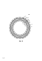
圖1為第1實施形態之鐵道車輛用煞車碟盤100的背面圖。圖2為圖1所示之煞車碟盤100的1/8圓部分立體圖。煞車碟盤單元100,連結於鐵道車輛的轉動構件(圖示省略)。轉動構件為環狀圓板,被固定於車軸並與車軸一起轉動。轉動構件譬如為車輪。
<First Embodiment>
[Structure of the brake disc]
Fig. 1 is a rear view of a
參考圖1及圖2,煞車碟盤100具備碟盤本體10、複數個鰭片20。Referring to FIG. 1 and FIG. 2 , the
碟盤本體10為環狀的圓板。碟盤本體10具有表面11及背面12。表面11,是可供煞車襯(圖示省略)壓附的滑動面。背面12,是表面11之相反方向的面。當煞車碟盤100已連結於轉動構件時,背面12面向轉動構件的側面。以下,為了說明上的方便,將碟盤本體10的半徑方向及圓周方向,稱為半徑方向及圓周方向,並將正交於半徑方向與圓周方向雙方的方向,稱為厚度方向。The
碟盤本體10,在其背面12上具有複數個突起13。各突起13,譬如成為半球狀、或者半橢球體狀。各突起13,亦可具有與其他突起13相同的形狀、或亦可具有與其他突起13不同的形狀。The
複數個鰭片20,在碟盤本體10的背面12上配置成放射狀。鰭片20,從碟盤本體10的內周側朝外周側延伸。鰭片20分別含有延伸於半徑方向的頂面21。當煞車碟盤100已連結於轉動構件時,頂面21接觸於轉動構件的側面。藉此,在轉動構件、於周方向相鄰的鰭片20、碟盤本體10之間形成有空間。這些空間,當煞車碟盤100與轉動構件一起轉動時,成為可供空氣通過的通氣路徑。A plurality of
鰭片20的至少其中一部分,在半徑方向的中央部具有螺栓孔22。在本實施形態的例子中,被配置於碟盤本體10之背面12上的複數個鰭片20中,僅一部分的鰭片20設有螺栓孔22。螺栓孔22,朝厚度方向貫穿鰭片20及碟盤本體10。當將煞車碟盤100連結於轉動構件時,將螺栓(圖示省略)插入螺栓孔22。At least a part of the
具有螺栓孔22的鰭片20,分別具有溝23、24。溝23、24,從頂面21朝碟盤本體10側成為凹陷的形狀。溝23、24,大致延伸於圓周方向並橫越鰭片20。
溝23、24,在半徑方向中被配置於螺栓孔22的兩側。溝23在半徑方向中被設在螺栓孔22的外側。溝24在半徑方向中被設在螺栓孔22的內側。溝23、24的形狀,並沒有特別的限制。溝23、24的壁面及底面,可藉由平面、凸曲面或凹曲面、或者前述各種面的組合所構成。在本實施形態中,不具有螺栓孔22的鰭片20,也具有溝23、24。The
參考圖3,更詳細地說明碟盤本體10及鰭片20的構造。圖3,為圖1所示之煞車碟盤100的III-III線剖面圖,亦即是沿著半徑方向切斷煞車碟盤100的剖面圖。以下,將「沿著半徑方向之煞車碟盤100的剖面」稱為「半徑方向剖面」。Referring to FIG. 3 , the structure of the
碟盤本體10含有外周部14與內周部15。內周部15,在半徑方向中,較螺栓孔22更位於內側。更詳細地說,內周部15,在半徑方向中,較溝24更位於內側。外周部14,是碟盤本體10之中,於半徑方向上位在比內周部15更外側的部分,並圍繞內周部15。The
外周部14含有主背面121。主背面121是背面12的主要部分。主背面121,是實質上平行於表面11的平面。因此,外周部14的厚度t0,在半徑方向上略呈一定(恆定)。厚度t0,是從主背面121到表面11為止之厚度方向的長度。厚度t0,譬如可形成17mm~25mm。The outer
前述的突起13,形成於主背面121上。更詳細地說,在圓周方向上相鄰的鰭片20之間,於主背面121上形成有複數個突起13。考慮到成形性,位於碟盤本體10之外周側的突起13,最好呈現半橢球體狀。其它的突起13,可形成半球狀。The
內周部15含有傾斜面122。傾斜面122,構成背面12的一部分。傾斜面122與主背面121連接。傾斜面122,雖然可以與主背面121直接連接,但亦可隔著C倒角或者R倒角而間接地與主背面121連接。The inner
傾斜面122,是朝向碟盤本體10的表面11側形成縮徑的圓錐面。在煞車碟盤100的半徑方向剖面視角中,傾斜面122以「在半徑方向上,越朝向內側則越接近表面11」的方式形成傾斜。在煞車碟盤100的半徑方向剖面視角中,傾斜面122與表面11所形成的角度α,最好是25°以上45°以下。The
藉由傾斜面122,內周部15的厚度,在半徑方向上越朝向內側則越小。亦即,內周部15,從外周部14側朝向碟盤本體10之內周側的緣部,緩緩地形成薄壁化。內周部15,在碟盤本體10的背面12之內周緣123的位置,具有最小厚度t1。The thickness of the inner
最小厚度t1是指:從背面12的內周緣123到表面11為止之厚度方向的長度。在本實施形態中,雖然在內周部15的表面11側設有缺口部,但最小厚度t1,是不考慮該缺口部的厚度。最小厚度t1,譬如可設定為3mm~12mm。「內周部15的最小厚度」對「外周部14的厚度」的比率t1/t0,最好是0.12~0.70。藉由使t1/t0形成0.12以上,在碟盤本體10的內周側可確保對最低限度之必要的熱容量及強度。另外,藉由使t1/t0形成0.70以下,使通氣路徑的開口面積擴大,在煞車碟盤100中可充分發揮「增加通氣路徑之風量」的效果。The minimum thickness t1 refers to the length in the thickness direction from the inner
如圖3所示,各鰭片20含有凸部25。凸部25,是鰭片20之中,在半徑方向較虛擬平面S1更朝內側突出的部分。在煞車碟盤100的半徑方向剖面視角中,凸部25被設在從虛擬平面S1到虛擬平面S2之間。虛擬平面S1,是通過「半徑方向中頂面21的兩端部211、212之中,位於內側的端部212」、與「碟盤本體10之背面12的內周緣123」的虛擬性平面。虛擬平面S2,是通過背面12的內周緣123並朝厚度方向延伸的虛擬性平面。As shown in FIG. 3 , each
凸部25,具有在半徑方向上向內的表面251。在本實施形態中,表面251是由平滑的曲面所構成。但是,表面251亦可由平面所構成。在煞車碟盤100的半徑方向剖面視角中,表面251可組合複數種類的曲線及/或直線而構成。The
具有螺栓孔22的鰭片20,在半徑方向中具有長度L0。內周部15,在半徑方向中具有長度L1。內周部15的長度L1,最好為鰭片20之長度L0的1/4以下。內周部15的長度L1,在煞車碟盤100的半徑方向剖面視角中,由從「背面12的內周緣123」到「傾斜面122的延長線與主背面121的延長線之間的交點」為止之半徑方向的長度所定義。鰭片20的長度L0,是鰭片20之半徑方向的最大長度。在本實施形態中,半徑方向內側之鰭片20端部的位置,與碟盤本體10之背面12的內周緣123的位置一致。The
[第1實施形態的效果]
在本實施形態的煞車碟盤100中,碟盤本體10之內周部15的厚度,在半徑方向上越朝內側變得越小。藉此,在煞車碟盤100的內周側,由「鐵道車輛的轉動構件」、「在圓周方向中相鄰的鰭片20」、「碟盤本體10」所形成之通氣路徑的剖面積被擴大。因此,在轉動構件的制動時,可促使「從煞車碟盤100的內周側流入通氣路徑內之空氣的量(通氣量)」增大。據此,煞車碟盤100,在制動時可發揮絕佳的冷卻性能。
[Effect of the first embodiment]
In the
在本實施形態中,藉由凸部25,在煞車碟盤100的內周側使鰭片20增量。因此,即便碟盤本體10的內周部15已形成薄壁化,也能在煞車碟盤100的內周側確保熱容量。據此,在制動時可避免煞車碟盤100的內周側局部地形成高溫化。其結果,在煞車碟盤100,可確保作為鐵道車輛用煞車碟盤所需求的耐久性。In this embodiment, the
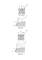
在促使煞車碟盤100之內周側的熱容量增加的場合,考慮在煞車碟盤100的內周側,使鰭片20的一部分朝圓周方向突出。舉例來說,如圖4所示,只要單純地使煞車碟盤100之內周側的熱容量增加,考慮在煞車碟盤100的內周側,將凸部26設在鰭片20的兩側面。但是,在該場合中,由於在煞車碟盤100的內周側通氣路徑的剖面積特別是朝圓周方向減少,因此通氣路徑內的通氣量減少。亦即,如同在圖4的上圖中標示剖面線所示,通氣路徑中空氣的流入面被凸部26所縮小,煞車碟盤100與轉動構件之間的通氣性下降。據此,煞車碟盤100的冷卻性能下降。不僅如此,在使鰭片20局部地朝圓周方向突出的場合中,在朝半徑方向延伸的通氣路徑中形成「剖面積急遽擴大」的部分。其結果,在通氣路徑,流動於其內部的空氣之壓力損失增大而使通氣量減少,在半徑方向越朝外側,空氣的流速及通氣路徑表面的熱傳導率下降。In order to increase the heat capacity on the inner peripheral side of the
或者,只要單純地使煞車碟盤100之內周側的熱容量增加,舉例來說,如圖5所示考慮在煞車碟盤100的內周側,將凸部17設在碟盤本體10的背面12上。但是,在該場合中,由於在煞車碟盤100的內周側通氣路徑的剖面積特別是朝厚度方向減少,因此通氣路徑內的通氣量減少。亦即,如同在圖5的上圖中標示剖面線所示,通氣路徑中空氣的流入面被凸部17所縮小,煞車碟盤100與轉動構件之間的通氣性下降。據此,煞車碟盤100的冷卻性能下降。Alternatively, as long as the heat capacity of the inner peripheral side of the
相對於此,在本實施形態中,於煞車碟盤100的內周側,使鰭片20朝半徑方向內側突出而形成凸部25。凸部25,由於未突出於通氣路徑內,因此在煞車碟盤100的內周側,實質上不會使通氣路徑的剖面積減少。亦即,通氣路徑中空氣的流入面不會被凸部25所縮小,可確保煞車碟盤100與轉動構件之間的良好通氣性。據此,在煞車碟盤100既能維持良好的冷卻性能,又能使熱容量增加。On the other hand, in this embodiment, on the inner peripheral side of the
此外,由於藉由朝半徑方向內側突出的凸部25而使鰭片20的表面積擴大,因此可獲得:更進一步促進煞車碟盤100冷卻的效果。據此,煞車碟盤100,在制動時可發揮更良好的冷卻性能。In addition, since the surface area of the
在本實施形態中,在各鰭片20形成有橫越鰭片本身的溝23、24。溝23、24的緣部和壁面,令「流動於通氣路徑的空氣」產生壓力損失,而降低通氣路徑的通氣量。因此,可抑制「制動時之氣動聲的產生」。另外,溝23、24擴大鰭片20的表面積,在制動時可促進煞車碟盤100的冷卻。據此,可確保制動時煞車碟盤100的冷卻性能。In the present embodiment,
在本實施形態中,所有的鰭片20,具有溝23、24。但是,溝23、24並非各鰭片20的必要構造,鰭片20的一部分或者全部亦可不具有溝23、24。舉例來說,也可以僅在設有螺栓孔22的鰭片20,形成溝23、24。In this embodiment, all the
半徑方向中煞車碟盤100之剛性的平衡,影響「碟盤本體10的剛性」及「鰭片20的剛性」的雙方。在煞車碟盤100的半徑方向剖面視角中,薄壁的內周部15接近溝24的場合,螺栓孔22之內周側的溝24附近的剛性,小於螺栓孔22之外周側的溝23附近的剛性。因此,在制動時,相對於螺栓孔22內的螺栓,非對稱的熱變形容易產生於煞車碟盤100,而使產生於螺栓的彎曲應力增大。其結果,有損及螺栓之耐久性的可能。The balance of the rigidity of the
可慮到這一點,在本實施形態中,將碟盤本體10之薄壁的內周部15,配置在比溝24更朝半徑方向內側。如此一來,在螺栓孔22的內周側與外周側,煞車碟盤100的剛性形成平衡,在制動時不易產生煞車碟盤100之非對稱的熱變形。據此,可抑制產生於「螺栓孔22內之螺栓」的彎曲應力,能確保螺栓的耐久性。Taking this point into consideration, in the present embodiment, the thin inner
在本實施形態中,碟盤本體10之內周部15的厚度,藉由傾斜面122,在半徑方向上朝外側緩緩地變大。因此,通氣路徑的剖面積,從碟盤本體10的內周側朝向外周側,在沒有急遽變化的狀態下緩緩地縮小。據此,可抑制「流動於通氣路徑內之空氣的壓力損失」,能充分地確保通氣路徑內的通氣量。In this embodiment, the thickness of the inner
在本實施形態的煞車碟盤100中,背面12的傾斜面122與表面11所形成的角度α,最好被設定成25°以上。如此一來,即使煞車碟盤100的熱變形時,也能維持傾斜面122對轉動構件的傾斜。In the
圖6為誇大表示煞車碟盤100之熱變形的圖。如圖6所示,在制動時,將鰭片20之頂面21的兩端部211、212作為支點,而煞車碟盤100熱變形成拱形的場合,煞車碟盤100的外周側及內周側接近轉動構件,轉動構件與傾斜面122之間的開口角(angular aperture;傾斜面122對轉動構件的傾斜)變小。有鑑於此,在本實施形態中,相對於表面11,使傾斜面122形成25°以上的傾斜,藉此可預先大幅地確保該開口角。因此,即使在煞車碟盤100已產生熱變形的場合,也能保持轉動構件與傾斜面122之間的開口角,可將轉動構件與背面12的內周緣123之間的距離(通氣路徑的入口面積)維持成一定的程度。據此,即使煞車碟盤100的熱變形時,也能抑制通氣路徑內之通氣量的減少,可確保制動時的高冷卻性能。此外,碟盤本體10中,薄壁之內周部15的範圍不會變得過大,能維持外周側與內周側之剛性的平衡。FIG. 6 is an exaggerated view showing thermal deformation of the
如圖6所示,考慮到煞車碟盤100熱變形成拱形的狀況,鰭片20的表面251,最好是由曲面所構成。只要表面251為曲面狀,即使是因熱變形而使鰭片20接觸於轉動構件的場合,也不容易由鰭片20對轉動構件造成損傷。As shown in FIG. 6 , considering that the
在本實施形態中,碟盤本體10之內周部15的半徑方向長度L1,最好設定成鰭片20之半徑方向長度L0的1/4以下。如此一來,碟盤本體10中,薄壁之內周部15的範圍受到限制。據此,在煞車碟盤100中,可維持螺栓孔22的外周側與內周側之間的剛性平衡,能抑制在螺栓孔22的外周側及內周側產生非對稱的熱變形。其結果,可抑制產生於「螺栓孔22內之螺栓」的彎曲應力,能確保螺栓的耐久性。In this embodiment, the radial length L1 of the inner
在本實施形態的煞車碟盤100中,內周部15的傾斜面122與表面11所形成的角度α,最好被設定成45°以下。在該場合中,通氣路徑的剖面積,從碟盤本體10的內周側朝向外周側,在沒有急遽變化的狀態下緩緩地縮小。據此,可抑制「流動於通氣路徑內之空氣的壓力損失」,能充分地確保通氣路徑內的通氣量。In the
在本實施形態的例子中,複數個突起13設於碟盤本體10的背面12上。由於藉由該突起13而使碟盤本體10的表面積擴大,因此可促進制動時之煞車碟盤100的冷卻。In the example of this embodiment, a plurality of
突起13並非碟盤本體10的必要構造。亦即,在碟盤本體10的背面12,亦可不設有突起13。The
<第2實施形態>
圖7為第2實施形態之煞車碟盤100A的半徑方向剖面圖。本實施形態的煞車碟盤100A,碟盤本體10A之內周部16的形狀,與第1實施形態的煞車碟盤100(圖3)不同。
<Second Embodiment>
Fig. 7 is a radial sectional view of a
內周部16含有曲面124。曲面124,構成背面12A的一部分。曲面124亦可由複合圓弧面所構成。曲面124與表面11之間的距離,在半徑方向中,朝向內側實質地變小。內周部16,與第1實施形態相同,在碟盤本體10A的背面12A之內周緣123的位置,具有最小厚度t1。The inner
在煞車碟盤100A的半徑方向剖面視角中,曲面124的切線T與表面11所形成的角度β,最好是25°以上45°以下。曲面124的切線T,是曲面124的切線之中,對表面11的傾斜最大的切線。藉由使角度β形成25°以上,與第1實施形態相同,即使在煞車碟盤100A已產生熱變形的場合,也能將背面12A的內周緣123與轉動構件之間的距離(通氣路徑之入口的開口面積)維持成一定的程度。此外,碟盤本體10A中,薄壁之內周部16的範圍不會變得過大,能維持外周側與內周側之剛性的平衡。另外,藉由使角度β形成45°以下,通氣路徑的剖面積,從碟盤本體10A的內周側朝向外周側,在沒有急遽變化的狀態下緩緩地縮小。據此,可抑制「流動於通氣路徑內之空氣的壓力損失」,能充分地確保通氣路徑內的通氣量。In the radial cross-sectional view of the
根據「限制碟盤本體10A中薄壁化之範圍」的觀點,內周部16的長度L1,與第1實施形態相同,最好設定成鰭片20之長度L0的1/4以下。內周部16的長度L1,在煞車碟盤100A的半徑方向剖面視角中,由從「背面12A的內周緣123」到「曲面124的切線T與主背面121的延長線之間的交點」為止之半徑方向的長度所定義。From the viewpoint of "limiting the thinning range of the
即使在本實施形態中,也和第1實施形態相同,碟盤本體10A之內周部16的厚度,在半徑方向上越朝內側變得越小。因此,在煞車碟盤100A的內周側,通氣路徑的剖面積擴大。據此,當制動鐵道車輛的轉動構件時,可增大通氣路徑內的通氣量,能使煞車碟盤100A發揮絕佳的冷卻性能。Also in this embodiment, as in the first embodiment, the thickness of the inner
以上,雖然說明了本發明的實施形態,但本發明並不侷限於上述實施形態,在不脫離本發明要旨的範圍內,能有各式各樣的變更。 [實施例] As mentioned above, although the embodiment of this invention was described, this invention is not limited to the said embodiment, Various changes are possible in the range which does not deviate from the summary of this invention. [Example]
以下,藉由實施例,更詳細地說明本發明。但是,本發明並不侷限於以下的實施例。Hereinafter, the present invention will be described in more detail by means of examples. However, the present invention is not limited to the following examples.
為了驗證本發明之鐵道車輛用煞車碟盤所帶來的效果,採用泛用熱流體分析軟體(製品名:ANSYS Fluent,ANSYS公司製),假設「鐵道車輛以360km/h恆定行駛」的場合而執行了三維熱流體分析。熱流體分析所使用之煞車碟盤的基本規格如下。 <基本規格> ・新幹線用的鍛鋼(forged steel)煞車碟盤 ・碟盤本體的內徑:466mm ・碟盤本體的外徑:722mm ・鰭片之半徑方向的長度L0:128mm ・螺栓孔:配置成中心位於直徑585mm的圓上 In order to verify the effect brought by the brake disc for railway vehicles of the present invention, a general-purpose thermal fluid analysis software (product name: ANSYS Fluent, manufactured by ANSYS Corporation) was used, assuming the situation of "a railway vehicle running at a constant speed of 360km/h". A 3D thermo-fluid analysis was performed. The basic specifications of brake discs used in thermal fluid analysis are as follows. <Basic Specifications> ・Forged steel brake discs for the Shinkansen ・Inner diameter of the disc body: 466mm ・Outer diameter of the disc body: 722mm ・The length L0 of the radial direction of the fin: 128mm ・Bolt holes: Arranged so that the center is on a circle with a diameter of 585mm
採用散熱指數,作為表示煞車碟盤之冷卻性能的評價指標。散熱指數,是碟盤表面的平均熱傳達率、與碟盤表面積的累計值(每1片煞車碟盤,360km/h恆定行駛時)。該散熱指數越高,則意味著煞車碟盤的冷卻性能高。The heat dissipation index is used as an evaluation index to express the cooling performance of the brake disc. The heat dissipation index is the cumulative value of the average heat transfer rate on the surface of the disc and the surface area of the disc (per 1 brake disc, when driving at a constant speed of 360km/h). The higher the heat dissipation index, the higher the cooling performance of the brake disc.
此外,採用通氣量,作為表示氣動聲之程度的評價指標。通氣量,是360km/h恆定行駛時,煞車碟盤與車輪(轉動構件)之間的通氣量。如同國際公開第2010/071169號的記載,「煞車碟盤與車輪之間的通氣量」與「氣動聲的程度」之間,具有強力的關聯。因此,將熱流體分析所獲得的通氣量(每個單位時間),作為用來評價氣動聲之程度的指標。可說是通氣量越大,氣動聲的程度也越大。In addition, the ventilation volume is used as an evaluation index indicating the degree of aerodynamic sound. The air flow is the air flow between the brake disc and the wheel (rotating member) when driving at a constant speed of 360km/h. As recorded in International Publication No. 2010/071169, there is a strong correlation between "the air flow between the brake disc and the wheel" and "the degree of aerodynamic sound". Therefore, the ventilation rate (per unit time) obtained by thermofluid analysis is used as an index for evaluating the degree of aeroacoustics. It can be said that the greater the ventilation volume, the greater the degree of aerodynamic sound.
圖8為顯示用於熱流體分析之各模型的半徑方向剖面的示意圖。實施例1~4的模型,與第1實施形態的煞車碟盤100相同,在碟盤本體10設有薄壁的內周部15,並且在鰭片20設有凸部25。實施例2及實施例4的模型,在碟盤本體10的背面12上設有複數個突起13。實施例3及實施例4的模型,在鰭片20設有溝23、24。Fig. 8 is a schematic diagram showing a radial section of each model used for thermal fluid analysis. The models of Examples 1 to 4 are similar to the
比較例1的模型,在碟盤本體10未設有薄壁的內周部15,並且在鰭片20未設有凸部25。比較例2的模型,雖在碟盤本體10設有薄壁的內周部15,但在鰭片20未設有凸部25。In the model of Comparative Example 1, the thin inner
在實施例1~4及比較例2中,內周部15的角度α設為39°,「內周部15的長度」對「鰭片20的長度」的比率L1/L0設為0.16。角度α及長度L0、L1的定義,如同上述實施形態(圖3)所說明。In Examples 1 to 4 and Comparative Example 2, the angle α of the inner
圖9是針對各模型,顯示利用熱流體分析所獲得之通氣量與散熱指數間之關係的圖表。如圖9所示,比較例2之模型的散熱指數,高於比較例1之模型的散熱指數。據此,得知藉由將薄壁的內周部15設在碟盤本體10,能提高煞車碟盤的冷卻性能。FIG. 9 is a graph showing, for each model, the relationship between airflow and heat dissipation index obtained by thermofluid analysis. As shown in FIG. 9 , the heat dissipation index of the model of Comparative Example 2 is higher than that of the model of Comparative Example 1. From this, it is found that the cooling performance of the brake rotor can be improved by providing the thin inner
實施例1~4之模型的散熱指數,更高於比較例2之模型的散熱指數。亦即,除了將薄壁的內周部15設在碟盤本體10,藉由將「朝半徑方向內側突出的凸部25」設在鰭片20,能使煞車碟盤具有絕佳的冷卻性能。The heat dissipation index of the models of Examples 1-4 is higher than that of the model of Comparative Example 2. That is, in addition to providing the thin-walled inner
實施例2~4之模型的散熱指數,高於實施例1之模型的散熱指數。藉由碟盤本體10的突起13及/或鰭片20的溝23、24而使煞車碟盤的表面積擴大,因此可更進一部提高煞車碟盤的冷卻性能。The heat dissipation index of the model of
實施例3及實施例4之模型的通氣量,小於實施例1及實施例2之模型的通氣量。據此,鰭片20的溝23、24,不僅能提高煞車碟盤的冷卻性能,也有助於氣動聲的降低。The ventilation volume of the model of embodiment 3 and embodiment 4 is less than the ventilation volume of the model of
100,100A:煞車碟盤
10,10A:碟盤本體
11:表面
12:背面
122:傾斜面
123:內周緣
124:曲面
13:突起
15,16:內周部
20:鰭片
21:頂面
22:螺栓孔
23,24:溝
25:凸部
100,100A:
[圖1]圖1為第1實施形態之鐵道車輛用煞車碟盤的背面圖。 [圖2]圖2為圖1所示之煞車碟盤的1/8圓部分立體圖。 [圖3]圖3為圖1所示之煞車碟盤的半徑方向剖面圖。 [圖4]圖4為顯示與第1實施形態之鐵道車輛用煞車碟盤進行比較之其它煞車碟盤的圖。 [圖5]圖5顯示與第1實施形態之鐵道車輛用煞車碟盤進行比較的其它煞車碟盤,是顯示與圖4所示的煞車碟盤不同之煞車碟盤的圖。 [圖6]圖6為誇大表示圖3所示之煞車碟盤的熱變形的圖。 [圖7]圖7為第2實施形態之鐵道車輛用煞車碟盤的半徑方向剖面圖。 [圖8]圖8為顯示用於熱流體分析之各模型的半徑方向剖面的示意圖。 [圖9]圖9是針對各模型,顯示利用熱流體分析所獲得之通氣量與散熱指數間之關係的圖表。 [ Fig. 1] Fig. 1 is a rear view of a brake disc for a railway vehicle according to a first embodiment. [ Fig. 2] Fig. 2 is a perspective view of a 1/8 circle portion of the brake disc shown in Fig. 1 . [ Fig. 3] Fig. 3 is a sectional view in the radial direction of the brake disc shown in Fig. 1 . [ Fig. 4] Fig. 4 is a diagram showing another brake disc for comparison with the brake disc for a railway vehicle according to the first embodiment. [ Fig. 5 ] Fig. 5 shows another brake disc for comparison with the brake disc for a railway vehicle according to the first embodiment, and is a view showing a brake disc different from the brake disc shown in Fig. 4 . [ Fig. 6] Fig. 6 is an exaggerated view showing thermal deformation of the brake disc shown in Fig. 3 . [ Fig. 7] Fig. 7 is a cross-sectional view in the radial direction of a brake disc for a railway vehicle according to a second embodiment. [ Fig. 8] Fig. 8 is a schematic view showing a section in the radial direction of each model used for thermal fluid analysis. [ Fig. 9] Fig. 9 is a graph showing, for each model, the relationship between the air flow rate obtained by thermal fluid analysis and the heat dissipation index.
L0,L1:長度
S1,S2:虛擬平面
t0,t1:厚度
α:角度
10:碟盤本體
11:表面
12:背面
13:突起
14:外周部
15:內周部
20:鰭片
21:頂面
22:螺栓孔
23,24:溝
25:凸部
100:煞車碟盤
121:主背面
122:傾斜面
123:內周緣
211,212:兩端部
251:表面
L0, L1: Length
S1, S2: virtual plane
t0, t1: thickness
α: angle
10: Disc body
11: surface
12: back
13: Protrusion
14: Peripheral part
15: Inner peripheral part
20: Fins
21: top surface
22:
Claims (6)
Applications Claiming Priority (2)
| Application Number | Priority Date | Filing Date | Title |
|---|---|---|---|
| JP2021-055971 | 2021-03-29 | ||
| JP2021055971A JP2022152986A (en) | 2021-03-29 | 2021-03-29 | Brake disc for railway vehicle |
Publications (2)
| Publication Number | Publication Date |
|---|---|
| TW202246095A TW202246095A (en) | 2022-12-01 |
| TWI794067B true TWI794067B (en) | 2023-02-21 |
Family
ID=83459196
Family Applications (1)
| Application Number | Title | Priority Date | Filing Date |
|---|---|---|---|
| TW111111662A TWI794067B (en) | 2021-03-29 | 2022-03-28 | Brake discs for railway vehicles |
Country Status (8)
| Country | Link |
|---|---|
| US (1) | US20240140501A1 (en) |
| EP (1) | EP4316941A1 (en) |
| JP (1) | JP2022152986A (en) |
| KR (1) | KR20230160379A (en) |
| CN (1) | CN117083471A (en) |
| BR (1) | BR112023018560A2 (en) |
| TW (1) | TWI794067B (en) |
| WO (1) | WO2022210474A1 (en) |
Citations (6)
| Publication number | Priority date | Publication date | Assignee | Title |
|---|---|---|---|---|
| EP0683331A1 (en) * | 1994-05-20 | 1995-11-22 | Knorr-Bremse Systeme für Schienenfahrzeuge GmbH | Wheel brake disc for railway vehicles |
| JP2006009862A (en) * | 2004-06-23 | 2006-01-12 | Sumitomo Metal Ind Ltd | Brake disk for rolling stock |
| WO2011051603A2 (en) * | 2009-10-28 | 2011-05-05 | Afe Metal | Railway brake disk |
| TW201420404A (en) * | 2012-09-07 | 2014-06-01 | Nippon Steel & Sumitomo Metal Corp | Brake disc used for railroad vehicle |
| US20150232108A1 (en) * | 2012-08-03 | 2015-08-20 | Knorr-Bremse Systems Für Schienenfahrzeuge Gmbh | Wheel brake disc |
| CN105518331A (en) * | 2013-04-12 | 2016-04-20 | 韦伯太克控股公司 | Brake disc assembly for a wheel |
Family Cites Families (3)
| Publication number | Priority date | Publication date | Assignee | Title |
|---|---|---|---|---|
| JPS521266B1 (en) | 1967-07-18 | 1977-01-13 | ||
| JP3521266B2 (en) | 1994-09-08 | 2004-04-19 | 株式会社豊田中央研究所 | Brake disc rotor |
| BRPI0921368B1 (en) | 2008-12-19 | 2020-06-09 | Nippon Steel & Sumitomo Metal Corp | railroad vehicle brake disc |
-
2021
- 2021-03-29 JP JP2021055971A patent/JP2022152986A/en active Pending
-
2022
- 2022-03-28 EP EP22780685.8A patent/EP4316941A1/en active Pending
- 2022-03-28 US US18/548,663 patent/US20240140501A1/en active Pending
- 2022-03-28 CN CN202280025111.0A patent/CN117083471A/en active Pending
- 2022-03-28 TW TW111111662A patent/TWI794067B/en active
- 2022-03-28 BR BR112023018560A patent/BR112023018560A2/en unknown
- 2022-03-28 WO PCT/JP2022/014828 patent/WO2022210474A1/en active Application Filing
- 2022-03-28 KR KR1020237036558A patent/KR20230160379A/en active Search and Examination
Patent Citations (6)
| Publication number | Priority date | Publication date | Assignee | Title |
|---|---|---|---|---|
| EP0683331A1 (en) * | 1994-05-20 | 1995-11-22 | Knorr-Bremse Systeme für Schienenfahrzeuge GmbH | Wheel brake disc for railway vehicles |
| JP2006009862A (en) * | 2004-06-23 | 2006-01-12 | Sumitomo Metal Ind Ltd | Brake disk for rolling stock |
| WO2011051603A2 (en) * | 2009-10-28 | 2011-05-05 | Afe Metal | Railway brake disk |
| US20150232108A1 (en) * | 2012-08-03 | 2015-08-20 | Knorr-Bremse Systems Für Schienenfahrzeuge Gmbh | Wheel brake disc |
| TW201420404A (en) * | 2012-09-07 | 2014-06-01 | Nippon Steel & Sumitomo Metal Corp | Brake disc used for railroad vehicle |
| CN105518331A (en) * | 2013-04-12 | 2016-04-20 | 韦伯太克控股公司 | Brake disc assembly for a wheel |
Also Published As
| Publication number | Publication date |
|---|---|
| WO2022210474A1 (en) | 2022-10-06 |
| BR112023018560A2 (en) | 2023-10-10 |
| TW202246095A (en) | 2022-12-01 |
| KR20230160379A (en) | 2023-11-23 |
| US20240140501A1 (en) | 2024-05-02 |
| CN117083471A (en) | 2023-11-17 |
| JP2022152986A (en) | 2022-10-12 |
| EP4316941A1 (en) | 2024-02-07 |
Similar Documents
| Publication | Publication Date | Title |
|---|---|---|
| TWI535947B (en) | Brake disc used for railroad vehicle | |
| JP4991534B2 (en) | Ventilated brake disc and corresponding car | |
| WO2002073060A1 (en) | Braking band and disc for disc brake | |
| US20150323025A1 (en) | Brake disc | |
| CN212225833U (en) | Brake disc | |
| TWI794067B (en) | Brake discs for railway vehicles | |
| TWI746175B (en) | Brake disc unit for railway vehicles | |
| JP6311554B2 (en) | Railway wheel with brake disc | |
| TWI807729B (en) | Brake discs for railway vehicles | |
| JP6923073B2 (en) | brake disc | |
| JP2000274463A (en) | Disc rotor and disc brake device using the disc rotor | |
| JP2021081039A (en) | Railroad vehicle disk brake device | |
| JP4509599B2 (en) | Brake disc rotor | |
| TWI772028B (en) | Disc brakes for railway vehicles | |
| WO2023127287A1 (en) | Disc brake device | |
| JP6419683B2 (en) | Disc brakes for automotive disc brakes | |
| WO2022210831A1 (en) | Brake disc | |
| CN220378766U (en) | Novel plane brake disc of wind channel structure | |
| JP7181109B2 (en) | brake disc | |
| CN214661642U (en) | C/SiC ventilation brake disc | |
| WO2015041039A1 (en) | Brake disc rotor | |
| KR102070699B1 (en) | Hub having improved efficiency of heat dissipation for disk of high speed trains | |
| CN117157472A (en) | Brake disc | |
| JP2017089670A (en) | Brake disc rotor |