TWI768923B - Alignment method of camera lens and light source - Google Patents

Alignment method of camera lens and light source Download PDF

Info

Publication number
TWI768923B
TWI768923B TW110118692A TW110118692A TWI768923B TW I768923 B TWI768923 B TW I768923B TW 110118692 A TW110118692 A TW 110118692A TW 110118692 A TW110118692 A TW 110118692A TW I768923 B TWI768923 B TW I768923B
Authority
TW
Taiwan
Prior art keywords
light source
camera lens
fixture
camera
result
Prior art date
Application number
TW110118692A
Other languages
Chinese (zh)
Other versions
TW202246851A (en
Inventor
王秀雯
林士文
Original Assignee
致伸科技股份有限公司
Priority date (The priority date is an assumption and is not a legal conclusion. Google has not performed a legal analysis and makes no representation as to the accuracy of the date listed.)
Filing date
Publication date
Application filed by 致伸科技股份有限公司 filed Critical 致伸科技股份有限公司
Priority to TW110118692A priority Critical patent/TWI768923B/en
Priority to US17/383,471 priority patent/US11509888B1/en
Application granted granted Critical
Publication of TWI768923B publication Critical patent/TWI768923B/en
Publication of TW202246851A publication Critical patent/TW202246851A/en

Links

Images

Classifications

    • HELECTRICITY
    • H04ELECTRIC COMMUNICATION TECHNIQUE
    • H04NPICTORIAL COMMUNICATION, e.g. TELEVISION
    • H04N17/00Diagnosis, testing or measuring for television systems or their details
    • H04N17/002Diagnosis, testing or measuring for television systems or their details for television cameras
    • GPHYSICS
    • G02OPTICS
    • G02BOPTICAL ELEMENTS, SYSTEMS OR APPARATUS
    • G02B7/00Mountings, adjusting means, or light-tight connections, for optical elements
    • G02B7/003Alignment of optical elements
    • HELECTRICITY
    • H04ELECTRIC COMMUNICATION TECHNIQUE
    • H04NPICTORIAL COMMUNICATION, e.g. TELEVISION
    • H04N23/00Cameras or camera modules comprising electronic image sensors; Control thereof
    • H04N23/50Constructional details
    • H04N23/55Optical parts specially adapted for electronic image sensors; Mounting thereof
    • HELECTRICITY
    • H04ELECTRIC COMMUNICATION TECHNIQUE
    • H04NPICTORIAL COMMUNICATION, e.g. TELEVISION
    • H04N23/00Cameras or camera modules comprising electronic image sensors; Control thereof
    • H04N23/56Cameras or camera modules comprising electronic image sensors; Control thereof provided with illuminating means
    • HELECTRICITY
    • H04ELECTRIC COMMUNICATION TECHNIQUE
    • H04NPICTORIAL COMMUNICATION, e.g. TELEVISION
    • H04N23/00Cameras or camera modules comprising electronic image sensors; Control thereof
    • H04N23/70Circuitry for compensating brightness variation in the scene
    • H04N23/71Circuitry for evaluating the brightness variation
    • HELECTRICITY
    • H04ELECTRIC COMMUNICATION TECHNIQUE
    • H04NPICTORIAL COMMUNICATION, e.g. TELEVISION
    • H04N23/00Cameras or camera modules comprising electronic image sensors; Control thereof
    • H04N23/70Circuitry for compensating brightness variation in the scene
    • H04N23/74Circuitry for compensating brightness variation in the scene by influencing the scene brightness using illuminating means

Abstract

The present invention relates to an alignment method of a camera lens and a light source, which is applied to an alignment system. The system includes an alignment plane, a reference camera and a fixture. The method includes steps of: photographing a reference chart on the alignment plane by the reference camera; placing a light source on the fixture; illuminating the alignment plane to form an illumination result by the light source, and capturing the illumination result by the reference camera; adjusting the light source by the fixture when the illumination result does not comply with a preset specification represented by the reference chart; placing a camera lens on the fixture; photographing the reference chart on the alignment plane by the camera lens to obtain a photographing result; and adjusting the camera lens by the fixture when the photographing result does not comply with the preset specification.

Description

相機鏡頭與光源之對位方法Alignment method of camera lens and light source

本發明是有關於一種相機鏡頭與光源之對位方法,且特別是有關於一種在組裝階段使光源的照射範圍和位置及相機鏡頭的拍攝範圍和位置相互對應的對位方法。The present invention relates to a method for aligning a camera lens and a light source, and more particularly, to a method for aligning the illumination range and position of the light source and the shooting range and position of the camera lens during assembly.

隨著3D影像感測技術的日漸發展,目前在許多行動電子裝置(例如數位相機、平板電腦、智慧型手機、智慧型手錶或穿戴式電子裝置)上也逐漸以具有3D影像感測功能的模組來作為其相機鏡頭及光源的配置。With the development of 3D image sensing technology, many mobile electronic devices (such as digital cameras, tablet computers, smart phones, smart watches or wearable electronic devices) are gradually using models with 3D image sensing functions. group as the configuration of its camera lens and light source.

目前3D影像感測技術主要包含有立體視覺(Stereo Vision)、結構光(Structured Light)、飛時測距(Time of Flight,簡稱TOF)等技術,而視應用的不同,其設計可採用一至多個相機鏡頭或是一至多個光源的配置來構成其3D影像感測模組。其次,所設置的光源可採用發光二極體(LED)、雷射二極體(LD)或垂直腔面發射雷射(VCSEL),並能以可見光、紅外光或近紅外光發出感測光。另外,其相機鏡頭則是根據所使用的光源的類型來作對應的設置。At present, 3D image sensing technology mainly includes stereo vision (Stereo Vision), structured light (Structured Light), time of flight (Time of Flight, TOF) and other technologies, and depending on the application, its design can use one or more The configuration of one camera lens or one or more light sources constitutes the 3D image sensing module. Secondly, the light source can be light emitting diode (LED), laser diode (LD) or vertical cavity surface emitting laser (VCSEL), and can emit sensing light in visible light, infrared light or near-infrared light. In addition, the camera lens is set according to the type of light source used.

就理想的狀態而言,光源在空間中的照射範圍和位置是相應於相機鏡頭的拍攝範圍和位置。然而,為達到較好的感測結果,設計上光源實際的照射範圍通常會略大於相機鏡頭的拍攝範圍。是以,光源與相機鏡頭在行動電子裝置或在所設置的電路板上就需要有良好的搭配。若兩者的搭配不佳,例如有偏差的情形時,相機鏡頭的部份拍攝範圍就無法被運用。換言之,於後續的計算與處理上,相機鏡頭(特別是其中的影像感測器)在相應位置上的像素點的感測應用就會被犧牲。In an ideal state, the illumination range and position of the light source in space correspond to the shooting range and position of the camera lens. However, in order to achieve better sensing results, the actual illumination range of the light source is usually slightly larger than the shooting range of the camera lens. Therefore, the light source and the camera lens need to be well matched on the mobile electronic device or on the circuit board provided. If the combination of the two is not good, such as when there is a deviation, part of the shooting range of the camera lens cannot be used. In other words, in the subsequent calculation and processing, the sensing application of the pixels at the corresponding positions of the camera lens (especially the image sensor) will be sacrificed.

是以,就組裝階段來說,光源與相機鏡頭之間必須透過調整與校正以使其照射和拍攝的範圍與位置相互對應。目前的方式可採用一自動光學檢測(Automated Optical Inspection,簡稱AOI)技術,利用例如機械手臂之治具和自動控制系統對光源與相機鏡頭進行機構限位上的組裝位置對應。詳細來說,可根據機械手臂的夾取結果的「機械視覺」去檢測相機鏡頭或光源的位置有無偏差,若無偏差情形時才進行組裝。但這樣的方式仍無法確定其照射和拍攝的範圍與位置相互對應。Therefore, in the assembly stage, the light source and the camera lens must be adjusted and corrected so that the range and position of the illumination and shooting correspond to each other. In the current method, an automated optical inspection (AOI) technology can be used, and a fixture such as a robotic arm and an automatic control system are used to correspond to the assembly position of the light source and the camera lens on the mechanical limit. In detail, the "mechanical vision" of the gripping result of the robotic arm can detect whether there is any deviation in the position of the camera lens or the light source, and assemble only if there is no deviation. However, in this way, it is still impossible to determine that the range and position of the irradiation and shooting correspond to each other.

或者,可先以相機鏡頭為準或以光源為準來進行調校。例如,先以一參考基準面對相機鏡頭進行調校,並作為光源組裝的基準面,再利用光源的均勻度來調校本身的組裝姿態。然而,此種分別以光源或相機鏡頭為參考基準的調校方式需要經過多次地調校才能完成對位的程序,故會耗費相當長的時間才能得到適合的對應關係,從而造成產線的效率下降。Alternatively, you can adjust the camera lens or the light source first. For example, the camera lens is first adjusted with a reference datum, which is used as the reference plane for light source assembly, and then the uniformity of the light source is used to adjust its assembly posture. However, this kind of adjustment method that takes the light source or the camera lens as the reference respectively needs to be adjusted many times to complete the alignment procedure, so it will take a long time to obtain a suitable corresponding relationship, which will cause the production line to fail. Efficiency drops.

本發明的目的在於提出一種相機鏡頭與光源之對位方法。該對位方法特別是應用在組裝階段以使光源的照射範圍和位置及相機鏡頭的拍攝範圍和位置相互對應,從而能減少因機構的對位誤差而需進行數位校正的影像處理時間,並能避免造成犠牲待組裝相機鏡頭的像素點的可能性。The purpose of the present invention is to provide a method for aligning a camera lens and a light source. The alignment method is especially applied in the assembly stage to make the irradiation range and position of the light source and the shooting range and position of the camera lens correspond to each other, thereby reducing the image processing time required for digital correction due to the alignment error of the mechanism, and can Avoid the possibility of sacrificing the pixels of the camera lens to be assembled.

本發明為一種相機鏡頭與光源之對位方法,應用於一對位系統上。該系統包含有一對位平面、一參考相機與一治具。該方法包含下列步驟:使該對位平面、該參考相機與該治具各自所在的平面相互平行,且該對位平面位於該參考相機與該治具之間;由該參考相機拍攝該對位平面上的一標定圖案;置放一光源於該治具上;由該光源照射該對位平面而形成一照射結果,並由該參考相機拍攝該照射結果;當該照射結果不符合該標定圖案所代表的一預設規格時,由該治具調整該光源;置放一相機鏡頭於該治具上;由該相機鏡頭拍攝該對位平面上的該標定圖案而得到一拍攝結果;以及當該拍攝結果不符合該預設規格時,由該治具調整該相機鏡頭。The present invention is a method for aligning a camera lens and a light source, which is applied to a aligning system. The system includes a pair of bit planes, a reference camera and a fixture. The method includes the following steps: making the alignment plane, the reference camera and the jig in parallel to each other, and the alignment plane is located between the reference camera and the jig; photographing the alignment plane by the reference camera A calibration pattern on the plane; a light source is placed on the fixture; an illumination result is formed by illuminating the alignment plane by the light source, and the illumination result is photographed by the reference camera; when the illumination result does not conform to the calibration pattern When a preset specification is represented, the light source is adjusted by the fixture; a camera lens is placed on the fixture; the calibration pattern on the alignment plane is photographed by the camera lens to obtain a photographing result; and when When the shooting result does not meet the preset specification, the camera lens is adjusted by the fixture.

本發明另一方面為一種相機鏡頭與光源之對位方法,應用於一對位系統上。該系統包含有一對位平面、一參考相機與一治具。該方法包含下列步驟:使該對位平面、該參考相機與該治具各自所在的平面相互平行,且該對位平面位於該參考相機與該治具之間;由該參考相機拍攝該對位平面上的一標定圖案;置放一相機鏡頭於該治具上;由該相機鏡頭拍攝該對位平面上的該標定圖案而得到一拍攝結果;當該拍攝結果不符合該標定圖案所代表的一預設規格時,由該治具調整該相機鏡頭;置放一光源於該治具上;由該光源照射該對位平面而形成一照射結果,並由該參考相機或該相機鏡頭拍攝該照射結果;以及當該照射結果不符合該預設規格時,由該治具調整該光源。Another aspect of the present invention is a method for aligning a camera lens and a light source, which is applied to an alignment system. The system includes a pair of bit planes, a reference camera and a fixture. The method includes the following steps: making the alignment plane, the reference camera and the jig in parallel to each other, and the alignment plane is located between the reference camera and the jig; photographing the alignment plane by the reference camera A calibration pattern on the plane; place a camera lens on the fixture; shoot the calibration pattern on the alignment plane with the camera lens to obtain a shooting result; when the shooting result does not conform to the calibration pattern represented In a preset specification, the camera lens is adjusted by the fixture; a light source is placed on the fixture; the light source illuminates the alignment plane to form an illumination result, and the reference camera or the camera lens captures the The irradiation result; and when the irradiation result does not meet the preset specification, the light source is adjusted by the fixture.

為了對本發明之上述及其他方面有更佳的瞭解,下文特舉實施例並配合所附圖式進行詳細說明。In order to have a better understanding of the above and other aspects of the present invention, the following embodiments are given and described in detail with the accompanying drawings.

以下係提出實施例進行詳細說明,實施例僅用以作為範例說明,並不會限縮本發明欲保護之範圍。此外,實施例中之圖式係省略不必要或以通常技術即可完成之元件,以清楚顯示本發明之技術特點。The following examples are provided for detailed description, and the examples are only used as examples to illustrate, and do not limit the scope of protection of the present invention. In addition, the drawings in the embodiments omit unnecessary elements or elements that can be completed with ordinary techniques, so as to clearly show the technical characteristics of the present invention.

現以一第一實施例進行本發明所提出之相機鏡頭與光源之對位方法的實施說明。請參見圖1A,為應用本發明的相機鏡頭與光源之對位方法的一對位系統100的平面示意圖。如圖1A所示,該對位系統100包含有一對位平面20、一參考相機10與一治具30,而其特徵在於,在空間中的配置是使該對位平面20、該參考相機10與該治具30各自所在的平面相互平行,且該對位平面20位於該參考相機10與該治具30之間,也就是該參考相機10與該治具30是分別位於該對位平面20的兩側。A first embodiment is now used to describe the implementation of the method for aligning a camera lens and a light source provided by the present invention. Please refer to FIG. 1A , which is a schematic plan view of an alignment system 100 applying the alignment method of a camera lens and a light source of the present invention. As shown in FIG. 1A , the alignment system 100 includes an alignment plane 20 , a reference camera 10 and a fixture 30 , and is characterized in that the alignment plane 20 , the reference camera 10 are arranged in space such that the alignment plane 20 and the reference camera 10 are arranged in space. The planes on which the fixture 30 is located are parallel to each other, and the alignment plane 20 is located between the reference camera 10 and the fixture 30 , that is, the reference camera 10 and the fixture 30 are located on the alignment plane 20 respectively. on both sides.

於此實施例中,該參考相機10是已經通過測試且確認為效能良好的一外部相機,以提供本發明的對位方法之應用。其次,該對位平面20具有光穿透性,並呈現出表面平整。換言之,該對位平面20是作為一種布幕。當某一光源照射於其上時,除了能在其中的一面顯示出光源的照射情形外,藉由部份光線的穿透,亦能在其相對的另一面上清楚地顯示光源的照射內容或影像範圍。另外,該治具30是一種可進行對位測試、調整校正和組裝等運作的工作機台,其上可置放應用本發明的對位方法之待測物件,即圖1A中的一相機鏡頭32與一光源31。In this embodiment, the reference camera 10 is an external camera that has been tested and confirmed to have good performance, so as to provide the application of the alignment method of the present invention. Secondly, the alignment plane 20 has light transmittance and presents a flat surface. In other words, the alignment plane 20 acts as a kind of curtain. When a light source shines on it, in addition to showing the illumination situation of the light source on one side, the illumination content of the light source can also be clearly displayed on the opposite side by the penetration of part of the light. Image range. In addition, the jig 30 is a workbench that can perform alignment testing, adjustment and calibration, and assembly operations, on which can place the object to be tested applying the alignment method of the present invention, that is, a camera lens in FIG. 1A 32 and a light source 31.

於圖1A還示意了該對位系統100還配置有一電腦裝置50,且該電腦裝置50是分別和該治具30與該參考相機10作信號連接。該電腦裝置50除了能接收該治具30與該參考相機10所產生的包括拍攝影像和運作狀態等內容之信號外,也是作為運作本發明的對位方法的主要控制及運算裝置。FIG. 1A also shows that the alignment system 100 is further configured with a computer device 50 , and the computer device 50 is respectively connected with the fixture 30 and the reference camera 10 for signal connection. The computer device 50 is not only capable of receiving the signals generated by the fixture 30 and the reference camera 10 including the captured image and the operation status, but also serves as the main control and computing device for operating the alignment method of the present invention.

請參見圖1B,為圖1A中的該對位平面20的正視示意圖。如圖1B所示,為運作本發明的對位方法,於該對位平面20的表面上繪製有一標定圖案40。於此實施例中,該標定圖案40具有多個特徵點41,這些特徵點41分別呈現出圓形與正方形,並分布在一特定範圍內的中央及各個角落。此外,該標定圖案40還包括了由多個特徵點41所共同組成的一棋盤格圖形42,這些特徵點41為黑白相間之正方形,且在部份的特徵點41中還具有顏色為對比的圓形。該棋盤格圖形42主要是位於所述的特定範圍的中央。Please refer to FIG. 1B , which is a schematic front view of the alignment plane 20 in FIG. 1A . As shown in FIG. 1B , in order to operate the alignment method of the present invention, a calibration pattern 40 is drawn on the surface of the alignment plane 20 . In this embodiment, the calibration pattern 40 has a plurality of feature points 41 , and the feature points 41 respectively present a circle and a square, and are distributed in the center and each corner within a specific range. In addition, the calibration pattern 40 also includes a checkerboard pattern 42 composed of a plurality of feature points 41. These feature points 41 are black and white squares, and some of the feature points 41 also have contrasting colors. round. The checkerboard pattern 42 is mainly located in the center of the specified range.

承上所述,該標定圖案40是作為本發明的對位方法之調整、校正的基準,也就是針對所要組裝的光源31與相機鏡頭32彼此之間是否能達到包括照射和拍攝的範圍與位置可相互對應的參考標準。另一方面,於此實施例中,作為外部相機的該參考相機10具有較高的解析度,且如圖1A所示,該參考相機10的一拍攝範圍F10(或視野)是設定為涵蓋該對位平面20的大部份範圍,也就是大於該標定圖案40的範圍。Continuing from the above, the calibration pattern 40 is used as a reference for the adjustment and correction of the alignment method of the present invention, that is, whether the light source 31 and the camera lens 32 to be assembled can reach the range and position including irradiation and shooting. Corresponding reference standards. On the other hand, in this embodiment, the reference camera 10 as an external camera has a higher resolution, and as shown in FIG. 1A , a shooting range F10 (or field of view) of the reference camera 10 is set to cover the Most of the area of the alignment plane 20 is larger than the area of the calibration pattern 40 .

為了達到較好的參考效果,此實施例是設計將該參考相機10的設置位置正對於該對位平面20上的該標定圖案40,使得當該參考相機10拍攝該標定圖案40時,該標定圖案40就會出現在整個拍攝影像的顯示範圍的正中央。如此,對於待組裝的該相機鏡頭32與該光源31之間後續所要分析的對位情形和所要判斷的調整程度,可以較方便地進行。In order to achieve a better reference effect, in this embodiment, the setting position of the reference camera 10 is designed to be aligned with the calibration pattern 40 on the alignment plane 20 , so that when the reference camera 10 captures the calibration pattern 40 , the calibration The pattern 40 will appear in the center of the display range of the entire captured image. In this way, the subsequent analysis of the alignment situation between the camera lens 32 to be assembled and the light source 31 and the adjustment degree to be judged can be performed more conveniently.

雖然在圖1A中同時示意了待組裝的該相機鏡頭32與該光源31,但需注意的是,本發明的該相機鏡頭32與該光源31是會被依序地做測試。詳細來說,本發明是設計可以先對該相機鏡頭32做測試,但也可以先對該光源31做測試,也就是尚未做測試的物件將不會出現在該治具30上。此外,由於該對位平面20具有光穿透性,故該標定圖案40除了會被該相機鏡頭32觀察到之外,也會被該參考相機10所觀察到。Although FIG. 1A shows the camera lens 32 and the light source 31 to be assembled at the same time, it should be noted that the camera lens 32 and the light source 31 of the present invention are tested in sequence. Specifically, the present invention is designed to test the camera lens 32 first, but also test the light source 31 first, that is, objects that have not been tested will not appear on the fixture 30 . In addition, since the alignment plane 20 has light transmittance, the calibration pattern 40 can be observed by the reference camera 10 in addition to the camera lens 32 .

另一方面,待組裝的該相機鏡頭32與該光源31於該治具30上的置放是置放在相應的支架(bracket)(未顯示於圖式)上,也就是在其所應用的電子裝置的電路板上有預設的組裝位置給該相機鏡頭32與該光源31進行組裝。因此,該相機鏡頭32與該光源31之間大致上是有固定的間距,而後續所要做的調整與校正則是在此一位置上進行三維的極小距離的平移或極小角度的偏轉,待測試完成後即進行組裝之固定。其次,該治具30於該對位平面20前方的設置位置可有類似的考量,例如可將該相機鏡頭32或該光源31正對於該標定圖案40。On the other hand, the placement of the camera lens 32 and the light source 31 to be assembled on the fixture 30 is placed on a corresponding bracket (not shown in the drawings), that is, in the applied bracket. There are preset assembly positions on the circuit board of the electronic device for the camera lens 32 to be assembled with the light source 31 . Therefore, there is generally a fixed distance between the camera lens 32 and the light source 31, and the subsequent adjustment and correction is to perform three-dimensional translation at this position with a minimum distance or deflection at a minimum angle, which is to be tested. Assemble and fix after completion. Secondly, the setting position of the fixture 30 in front of the alignment plane 20 may have similar considerations, for example, the camera lens 32 or the light source 31 may face the calibration pattern 40 .

請參見圖2,為本發明的相機鏡頭與光源之對位方法的第一實施例的流程圖。需注意的是,此第一實施例是先對該光源31做測試,再對該相機鏡頭32做測試。首先,使該對位平面20、該參考相機10與該治具30各自所在的平面相互平行,且該對位平面20位於該參考相機10與該治具30之間(步驟S101);其次,由該參考相機10拍攝該對位平面20上的一標定圖案40(步驟S102);之後,置放一光源31於該治具30上(步驟S103);接著,由該光源31照射該對位平面20而形成一照射結果,並由該參考相機10拍攝該照射結果(步驟S104);接著,判斷該照射結果是否符合該標定圖案40所代表的一預設規格(步驟S105);其中,當該照射結果不符合該標定圖案40所代表的該預設規格時,由該治具30調整該光源31(步驟S106);之後,置放一相機鏡頭32於該治具30上(步驟S107);接著,由該相機鏡頭32拍攝該對位平面20上的該標定圖案40而得到一拍攝結果(步驟S108);接著,判斷該拍攝結果是否符合該預設規格(步驟S109);其中,當該拍攝結果不符合該預設規格時,由該治具30調整該相機鏡頭32(步驟S110);最後,完成該相機鏡頭32與該光源31之對位(步驟S111)。Please refer to FIG. 2 , which is a flowchart of a first embodiment of a method for aligning a camera lens and a light source according to the present invention. It should be noted that, in this first embodiment, the light source 31 is tested first, and then the camera lens 32 is tested. First, make the alignment plane 20, the reference camera 10 and the jig 30 are parallel to each other, and the alignment plane 20 is located between the reference camera 10 and the jig 30 (step S101); secondly, A calibration pattern 40 on the alignment plane 20 is photographed by the reference camera 10 (step S102 ); after that, a light source 31 is placed on the fixture 30 (step S103 ); then, the alignment is illuminated by the light source 31 plane 20 to form an irradiation result, and the irradiation result is photographed by the reference camera 10 (step S104 ); then, it is determined whether the irradiation result conforms to a preset specification represented by the calibration pattern 40 (step S105 ); wherein, when When the irradiation result does not meet the preset specification represented by the calibration pattern 40, the light source 31 is adjusted by the fixture 30 (step S106); after that, a camera lens 32 is placed on the fixture 30 (step S107) Then, the calibration pattern 40 on the alignment plane 20 is photographed by the camera lens 32 to obtain a photographing result (step S108); then, it is judged whether the photographing result complies with the preset specification (step S109); wherein, when When the shooting result does not meet the preset specification, the camera lens 32 is adjusted by the fixture 30 (step S110 ); finally, the alignment of the camera lens 32 and the light source 31 is completed (step S111 ).

針對所述步驟S101,如前所述,本發明的特徵是採用相互平行的該對位平面20、該參考相機10與該治具30。而當這三者所在的平面相互平行時,能讓後續在組裝該相機鏡頭32與該光源31時所要處理的對位或傾斜情況的變因全都歸結到該治具30的控制上,也就是將該治具30在進行調整與校正所可能存在的其他影響因素都予以排除。換句話說,步驟S101必需在實際測試開始前就先完成。For the step S101 , as mentioned above, the present invention is characterized in that the alignment plane 20 , the reference camera 10 and the jig 30 are parallel to each other. When the planes where the three are located are parallel to each other, the causes of the alignment or inclination to be dealt with in the subsequent assembly of the camera lens 32 and the light source 31 can be attributed to the control of the fixture 30, that is, All other influencing factors that may exist in the adjustment and calibration of the fixture 30 are excluded. In other words, step S101 must be completed before the actual test starts.

本發明能以多種方式讓上述三者相互平行。舉例來說,將該對位平面20設置於該參考相機10與該治具30之間後,利用一水平儀調整該對位平面20、該參考相機10與該治具30而使該對位平面20、該參考相機10與該治具30各自所在的平面相互平行。根據目前技術,習知的雷射水平儀可藉由射出的雷射光束來判斷在被照射面上是否呈現垂直,從而能判斷與被照射面之間是否相互平行。The present invention can make the above three parallel to each other in various ways. For example, after the alignment plane 20 is set between the reference camera 10 and the fixture 30, a spirit level is used to adjust the alignment plane 20, the reference camera 10 and the fixture 30 to make the alignment plane 20. The planes on which the reference camera 10 and the fixture 30 are located are parallel to each other. According to the current technology, the conventional laser level can judge whether the irradiated surface is vertical by the emitted laser beam, so as to judge whether the irradiated surface is parallel to each other.

或者,將該對位平面20設置於該參考相機10與該治具30之間後,分別從該參考相機10與該治具30上拍攝該對位平面20上的該標定圖案40而分別得到一傾斜程度,並分別根據相應的該傾斜程度調整該參考相機10與該治具30而使該對位平面20、該參考相機10與該治具30各自所在的平面相互平行。詳細來說,可在該參考相機10與該治具30所在的平面上使用一標準相機(該參考相機10本身可直接使用)來分別拍攝該標定圖案40,若看到的各特徵點41有非正方形或非圓形的樣式時,代表兩平面之間有傾斜情形。相反的,若看到的各特徵點41是正方形或圓形的樣式時,代表兩平面之間為平行。上述的傾斜程度之判斷可由該電腦裝置50來進行,並分別對該參考相機10與該治具30提供調整的指示。Alternatively, after the alignment plane 20 is disposed between the reference camera 10 and the fixture 30 , the calibration pattern 40 on the alignment plane 20 is photographed from the reference camera 10 and the fixture 30 to obtain respectively The reference camera 10 and the jig 30 are adjusted according to the corresponding inclination degrees so that the alignment plane 20 , the planes on which the reference camera 10 and the jig 30 are respectively located are parallel to each other. In detail, a standard camera (the reference camera 10 itself can be used directly) can be used on the plane where the reference camera 10 and the fixture 30 are located to take pictures of the calibration pattern 40 respectively. If the feature points 41 seen have A non-square or non-circular style means that there is an inclination between the two planes. On the contrary, if each feature point 41 seen is in the form of a square or a circle, it means that the two planes are parallel. The above-mentioned determination of the degree of inclination can be performed by the computer device 50, and the reference camera 10 and the jig 30 are provided with adjustment instructions respectively.

針對所述步驟S102~S104,該參考相機10拍攝該標定圖案40之目的在於設定後續要進行比較的參考標準,而該電腦裝置50能對該參考相機10所取得的該標定圖案40的影像進行記錄、處理與分析,並在該對位平面20上對各特徵點41定義出相應的座標位置。由於是先測試該光源31,故此一階段在該治具30上的僅有該光源31。其次,該參考相機10接著再拍攝該光源31所產生的該照射結果,並將該照射結果傳給該電腦裝置50,該電腦裝置50可藉由找尋該光源31的最高亮度位置而得知其分佈範圍,並亦在該對位平面20上定義出該照射結果的座標位置。如此,該電腦裝置50能將所得到的該標定圖案40與該照射結果相互比較。For the steps S102 to S104 , the purpose of photographing the calibration pattern 40 by the reference camera 10 is to set a reference standard to be compared later, and the computer device 50 can perform the image processing of the calibration pattern 40 obtained by the reference camera 10 on the image of the calibration pattern 40 . Record, process and analyze, and define corresponding coordinate positions for each feature point 41 on the alignment plane 20 . Since the light source 31 is tested first, only the light source 31 is on the fixture 30 at this stage. Next, the reference camera 10 then captures the illumination result generated by the light source 31, and transmits the illumination result to the computer device 50, and the computer device 50 can find out the position of the highest brightness of the light source 31 to know the illumination result. distribution range, and also define the coordinate position of the irradiation result on the alignment plane 20 . In this way, the computer device 50 can compare the obtained calibration pattern 40 with the irradiation result.

針對所述步驟S105~S106,承上所述,此實施例中的該預設規格可為待組裝的該相機鏡頭32與該光源31於應用狀態下要能彼此相互對應的條件,故該標定圖案40需依此條件而繪製於該對位平面20上。此外,由於該光源31的照射範圍和位置及該相機鏡頭32的拍攝範圍和位置亦會和該光源31或該相機鏡頭32與該對位平面20之間的距離有關,故在設計該標定圖案40時除了須考量該對位平面20與該參考相機10之間距外,亦應考量該對位平面20與該治具30之間距。For the steps S105-S106, the preset specification in this embodiment can be the condition that the camera lens 32 and the light source 31 to be assembled can correspond to each other in the application state, so the calibration The pattern 40 needs to be drawn on the alignment plane 20 according to this condition. In addition, since the irradiation range and position of the light source 31 and the shooting range and position of the camera lens 32 are also related to the distance between the light source 31 or the camera lens 32 and the alignment plane 20, the calibration pattern is designed In addition to the distance between the alignment plane 20 and the reference camera 10 , the distance between the alignment plane 20 and the jig 30 should also be considered at 40 .

由此觀之,本發明的該預設規格可包含有一預設範圍、一預設位置、一預設形狀和一預設尺寸。若該照射結果的範圍是未對應到該預設範圍(即該標定圖案40的範圍)時,就代表不符合規格;或是若該照射結果所具有的結構光圖案或範圍其形狀呈現偏轉或傾斜時,也代表不符合規格。另外,由該照射結果的位置和分佈範圍的尺寸也可和該預設規格的位置、尺寸進行比較,從而能提供是否有偏差情形的判斷。From this point of view, the predetermined specification of the present invention may include a predetermined range, a predetermined position, a predetermined shape and a predetermined size. If the range of the irradiation result does not correspond to the preset range (that is, the range of the calibration pattern 40 ), it means that it does not meet the specification; or if the structured light pattern or range of the irradiation result has a shape that is deflected or When tilted, it also means out of specification. In addition, the position and size of the distribution range of the irradiation result can also be compared with the position and size of the preset specification, so as to provide a judgment on whether there is a deviation.

請參見圖3A,為本發明的一照射結果F31與該標定圖案40於一測試階段的情況示意圖。以圖3A所示為例,由於該照射結果F31的範圍未對應到該標定圖案40的範圍,故被判斷為不符合規格。當然,實際可能的情況並不限於此。舉例來說,若一照射結果的範圍可完全對應到該標定圖案40的範圍,但卻出現形狀傾斜或顯示位置偏差時,則亦會被判斷為不符合規格。是以,當該照射結果符合該預設規格時,就可進行後續的其他程序;而當該照射結果不符合該預設規格時,就需要進行步驟S106的調整程序。Please refer to FIG. 3A , which is a schematic diagram of an irradiation result F31 and the calibration pattern 40 in a test stage of the present invention. Taking the example shown in FIG. 3A , since the range of the irradiation result F31 does not correspond to the range of the calibration pattern 40 , it is judged to be out of specification. Of course, the actual possible situation is not limited to this. For example, if the range of an irradiation result can completely correspond to the range of the calibration pattern 40, but the shape is inclined or the display position is deviated, it will also be judged as not conforming to the specification. Therefore, when the irradiation result meets the predetermined specification, other subsequent procedures can be performed; and when the irradiation result does not meet the predetermined specification, the adjustment procedure of step S106 needs to be performed.

圖3A所示的影像內容可代表該參考相機10所看到的拍攝範圍F10,同時也是該電腦裝置50所進行分析的畫面。因此,步驟S106的細節可包含下列步驟:由該電腦裝置50分析該照射結果與該預設規格之間的差異而產生一光源調整對策;以及該電腦裝置50將該光源調整對策發送至該治具30,並由該治具30根據該光源調整對策調整該光源31。所述的調整可為對該光源31進行三維的平移或偏轉,也就是要往哪個方向平移、平移多少,或是往哪個方向偏轉、偏轉多少,從而使例如圖3A的該照射結果F31的範圍與該標定圖案40的範圍形成重疊或中心對準。由於調整可能無法一次完成,故設計當步驟S106完成之後再重覆步驟S104~S105以再做新狀態的判斷,從而完成該光源31與該標定圖案40之間的相應與對位。The image content shown in FIG. 3A can represent the shooting range F10 seen by the reference camera 10 , and is also the image analyzed by the computer device 50 . Therefore, the details of step S106 may include the following steps: the computer device 50 analyzes the difference between the irradiation result and the preset specification to generate a light source adjustment strategy; and the computer device 50 sends the light source adjustment strategy to the treatment device 50 The fixture 30 is used to adjust the light source 31 according to the light source adjustment strategy. The adjustment can be three-dimensional translation or deflection of the light source 31, that is, in which direction to translate and how much to translate, or in which direction and how much to deflect, so that, for example, the range of the illumination result F31 in FIG. 3A is changed. Overlap or center alignment with the extent of the calibration pattern 40 . Since the adjustment may not be completed at one time, it is designed to repeat steps S104 to S105 after step S106 to determine a new state, thereby completing the correspondence and alignment between the light source 31 and the calibration pattern 40 .

舉例來說,由於無論是面光源或點光源在進行照射時,也都會有要符合的照射形狀、照射範圍或照射位置的標準,因此,步驟S106的該電腦裝置50可進行以下的計算或分析:將該照射結果以形態學(Morphology)進行處理,並萃取出其中的特徵,進而取得該照射結果的中心座標。接著,可將此一中心座標投影至該參考相機10所拍攝到圓形的該特徵點41的中心座標,以求得空間變換矩陣,並進一步求解出其相應的旋轉矩陣,即可獲得姿態調整參數。For example, since no matter whether it is a surface light source or a point light source, there will be standards for the irradiation shape, irradiation range or irradiation position to be met. Therefore, the computer device 50 in step S106 can perform the following calculation or analysis : The irradiation result is processed by Morphology, and the features therein are extracted, and then the center coordinates of the irradiation result are obtained. Then, the center coordinate can be projected to the center coordinate of the circular feature point 41 captured by the reference camera 10 to obtain the space transformation matrix, and further solve the corresponding rotation matrix to obtain the attitude adjustment parameter.

再者,於完成該光源31的測試後,即步驟S105與步驟S107之間的階段,於其他實施例中可進一步設計:當該照射結果符合該預設規格時,將該光源31固定於一印刷電路板(未顯示於圖式)上。如此便能完成該光源31的對位與組裝。Furthermore, after the test of the light source 31 is completed, that is, the stage between step S105 and step S107, in other embodiments, it can be further designed: when the irradiation result meets the preset specification, the light source 31 is fixed in a on a printed circuit board (not shown). In this way, the alignment and assembly of the light source 31 can be completed.

針對所述步驟S107~S108,此一階段在該治具30上的有已調整好的該光源31以及待測試的該相機鏡頭32。其次,由於該相機鏡頭32本身可進行拍攝,也就是從該相機鏡頭32對該標定圖案40拍攝所得到的該拍攝結果可提供分析,從而能知道其分佈是否在所需的位置上。再加上該電腦裝置50已記錄了該標定圖案40的座標位置,故此一階段的該參考相機10可不用再拍攝。是以,該治具30能將該拍攝結果傳給該電腦裝置50,該電腦裝置50可藉由影像分析而得知該拍攝結果的分佈範圍,例如將該標定圖案40在該對位平面20上的座標位置換算成在該拍攝結果中的座標位置,進而可在該對位平面20上定義出該拍攝結果的座標位置。For the steps S107 - S108 , at this stage, the light source 31 and the camera lens 32 to be tested are already adjusted on the fixture 30 . Secondly, since the camera lens 32 can shoot itself, that is, the shooting result obtained from shooting the calibration pattern 40 by the camera lens 32 can provide analysis, so as to know whether its distribution is in the required position. In addition, the computer device 50 has recorded the coordinate position of the calibration pattern 40, so the reference camera 10 in this stage does not need to take pictures. Therefore, the jig 30 can transmit the shooting result to the computer device 50 , and the computer device 50 can know the distribution range of the shooting result through image analysis, for example, the calibration pattern 40 on the alignment plane 20 The coordinate position on the photographing result is converted into the coordinate position in the photographing result, and then the coordinate position of the photographing result can be defined on the alignment plane 20 .

針對所述步驟S109~S110,類似地,該標定圖案40所代表的該預設規格包含有該預設範圍、該預設位置、該預設形狀和該預設尺寸。若該拍攝結果的範圍是未對應到該標定圖案40的範圍時,就代表不符合規格;或是若該拍攝結果所看到的該標定圖案40其形狀呈現偏轉或傾斜時,也代表不符合規格。For the steps S109 to S110 , similarly, the preset specification represented by the calibration pattern 40 includes the preset range, the preset position, the preset shape and the preset size. If the range of the photographing result does not correspond to the range of the calibration pattern 40 , it means that it does not meet the specification; or if the shape of the calibration pattern 40 seen in the photographing result is deflected or inclined, it also means that it does not meet the specification. Specification.

請參見圖3B,為本發明的一拍攝結果F32與該標定圖案40於一測試階段的情況示意圖。於此實施例中,此一階段對該拍攝結果F32的判斷是分析該拍攝結果F32中的該標定圖案40;例如,該標定圖案40的各特徵點41是否呈現在指定的位置上,或是分析這些特徵點41的形狀是否水平或無傾斜。以圖3B所示為例,由於該拍攝結果F32的範圍未對應到該標定圖案40的範圍,造成各特徵點41的位置錯誤,故被判斷為不符合規格。是以,當該拍攝結果符合該預設規格時,即完成對位程序(步驟S111),或可再進行其他程序;而當該拍攝結果不符合該預設規格時,就需要進行步驟S110的調整程序。Please refer to FIG. 3B , which is a schematic diagram of a photographing result F32 and the calibration pattern 40 in a test stage of the present invention. In this embodiment, the determination of the photographing result F32 at this stage is to analyze the calibration pattern 40 in the photographing result F32; It is analyzed whether the shape of these feature points 41 is horizontal or not inclined. Taking the example shown in FIG. 3B , since the range of the photographing result F32 does not correspond to the range of the calibration pattern 40 , the position of each feature point 41 is wrong, so it is judged to be out of specification. Therefore, when the shooting result meets the preset specification, the alignment procedure is completed (step S111 ), or other procedures can be performed; and when the shooting result does not meet the preset specification, step S110 needs to be performed. Adjustment Program.

圖3B所示的影像內容可代表該相機鏡頭32所看到的拍攝結果F32,同時也是該電腦裝置50所進行分析的畫面。因此,步驟S110的細節可包含下列步驟:由該電腦裝置50分析該拍攝結果與該預設規格之間的差異而產生一相機鏡頭調整對策;以及該電腦裝置50將該相機鏡頭調整對策發送至該治具30,並由該治具30根據該相機鏡頭調整對策調整該相機鏡頭32。所述的調整可為對該相機鏡頭32進行三維的平移或偏轉,也就是要往哪個方向平移、平移多少,或是往哪個方向偏轉、偏轉多少,從而使例如圖3B的該拍攝結果F32的範圍與該標定圖案40的範圍形成重疊或中心對準。類似地,可設計當步驟S110完成之後再重覆步驟S108~S109以再做新狀態的判斷,從而完成該相機鏡頭32與該標定圖案40之間的相應與對位。The image content shown in FIG. 3B can represent the photographing result F32 seen by the camera lens 32 , and is also the image analyzed by the computer device 50 . Therefore, the details of step S110 may include the following steps: the computer device 50 analyzes the difference between the shooting result and the preset specification to generate a camera lens adjustment strategy; and the computer device 50 sends the camera lens adjustment strategy to The jig 30 adjusts the camera lens 32 according to the camera lens adjustment countermeasure by the jig 30 . The adjustment may be three-dimensional translation or deflection of the camera lens 32, that is, in which direction to translate and how much to translate, or in which direction and how much to deflect, so that, for example, the photographing result F32 in FIG. The extents overlap or center-align with the extents of the calibration pattern 40 . Similarly, after step S110 is completed, steps S108 to S109 can be repeated to determine a new state, so as to complete the correspondence and alignment between the camera lens 32 and the calibration pattern 40 .

舉例來說,步驟S110的該電腦裝置50可進行以下的計算:針對其中正方形的該特徵點41,該參考相機10或該相機鏡頭32所拍攝到的該特徵點41的四個角的點座標(u,v)可與理想正方形的點座標(x,y)先做正規化,而將拍攝到的點座標投影至正方形的點座標,以求得空間變換矩陣。其算式為:

Figure 02_image001
其中,定義U為
Figure 02_image003
,X為
Figure 02_image005
,T為
Figure 02_image007
, 也就是U=X×T。因此,T=X -1×U,T即為空間變換矩陣。再將空間變換矩陣T轉置後獲得拍攝影像與理想正方形的點座標之間的單應性矩陣(Homography Matrix),最後將矩陣的引數以外積求解出旋轉矩陣,此旋轉矩陣即可獲得姿態調整參數。當然,在進行正規化的計算時,除了可針對正方形的該特徵點41的四個角之外,亦可如上所述的針對圓形的該特徵點41的中心來求得空間變換矩陣。 For example, the computer device 50 in step S110 may perform the following calculation: for the feature point 41 in the square, the point coordinates of the four corners of the feature point 41 captured by the reference camera 10 or the camera lens 32 (u, v) can be normalized with the point coordinates (x, y) of an ideal square, and then the captured point coordinates are projected to the square point coordinates to obtain the space transformation matrix. Its formula is:
Figure 02_image001
Among them, define U as
Figure 02_image003
, X is
Figure 02_image005
, T is
Figure 02_image007
, which is U=X×T. Therefore, T=X -1 ×U, T is the space transformation matrix. Then transpose the space transformation matrix T to obtain the homography matrix (Homography Matrix) between the shot image and the point coordinates of the ideal square, and finally solve the rotation matrix by the outer product of the arguments of the matrix, and the attitude can be obtained by this rotation matrix. Adjustment parameters. Of course, in the normalization calculation, in addition to the four corners of the feature point 41 of the square, the space transformation matrix can also be obtained for the center of the feature point 41 of the circle as described above.

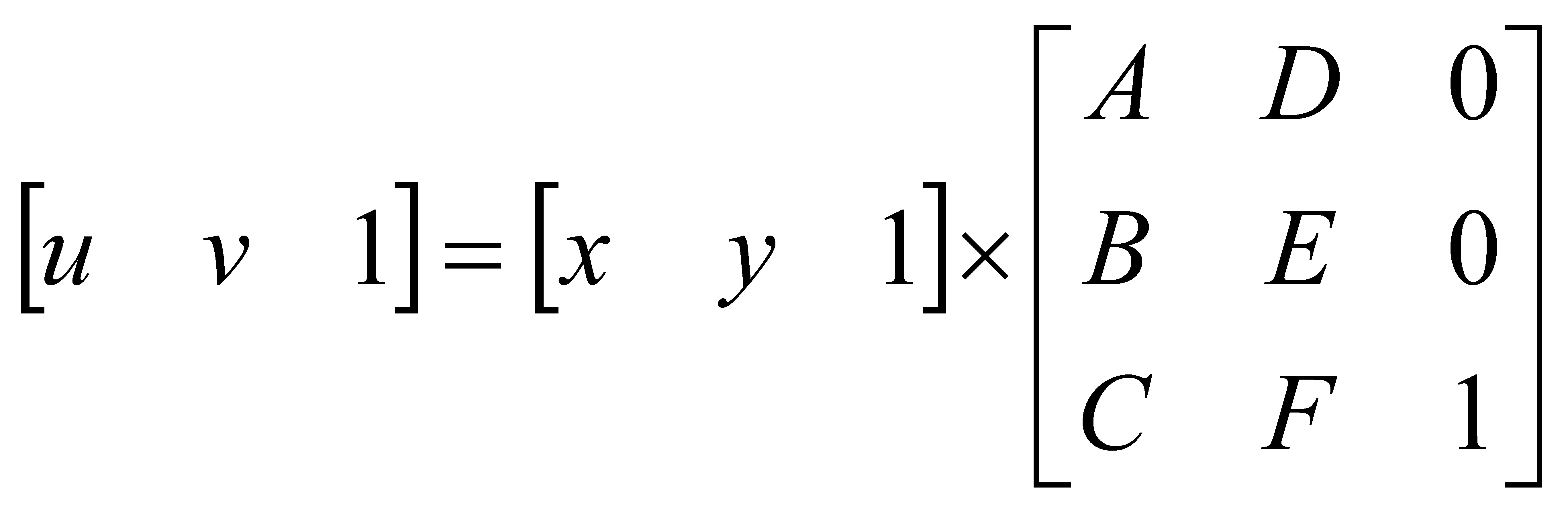
再者,於完成該相機鏡頭32的測試後,即步驟S109與步驟S111之間的階段,於其他實施例中可進一步設計:當該拍攝結果符合該預設規格時,將該相機鏡頭32固定於一印刷電路板(未顯示於圖式)上。如此便能完成該相機鏡頭32的對位與組裝。是以,該光源31與該標定圖案40之間完成了相應與對位,而該相機鏡頭32與該標定圖案40之間也完成了相應與對位,代表該光源31與該相機鏡頭32之間完成了相應與對位。Furthermore, after the test of the camera lens 32 is completed, that is, the stage between step S109 and step S111, in other embodiments, it can be further designed: when the shooting result meets the preset specification, the camera lens 32 is fixed. on a printed circuit board (not shown). In this way, the alignment and assembly of the camera lens 32 can be completed. Therefore, the correspondence and alignment between the light source 31 and the calibration pattern 40 are completed, and the correspondence and alignment between the camera lens 32 and the calibration pattern 40 are also completed, representing the relationship between the light source 31 and the camera lens 32 Correspondence and alignment are completed in time.

需注意的是,上述第一實施例的該預設規格的設定是以一個光源與一個相機鏡頭的設置作實施說明,因此在判斷彼此是否對應時,可以對其範圍是否重疊、涵蓋或是其中心點是否相互對準等判斷方式來進行。然而,若所應用的光源或相機鏡頭不只一個時,該預設規格的設定可以作相應的改變。舉例來說,若設置的相機鏡頭為兩個時,則每一相機鏡頭的拍攝範圍可以僅涵蓋該標定圖案40相應的一半範圍即可,因後續可再藉由影像處理來將兩相機鏡頭的拍攝結果進行組合、拼接。It should be noted that the setting of the preset specification in the above-mentioned first embodiment is implemented by the setting of one light source and one camera lens, so when judging whether they correspond to each other, it is possible to determine whether their ranges overlap, cover or otherwise. Whether the center points are aligned with each other is determined. However, if more than one light source or camera lens is used, the setting of the default specification can be changed accordingly. For example, if there are two camera lenses, the shooting range of each camera lens can only cover half of the corresponding range of the calibration pattern 40, because the subsequent image processing can be used to combine the two camera lenses. The shooting results are combined and stitched.

上述第一實施例是以一個光源與一個相機鏡頭的設置作實施說明,但可以理解的是本發明並不限於此。換言之,本發明的對位方法亦可視其3D影像感測應用的不同而對多個光源或多個相機鏡頭的組裝進行應用。是以,本發明還可根據上述第一實施例所揭露的概念作其他的變化。The above-mentioned first embodiment is described by the arrangement of one light source and one camera lens, but it should be understood that the present invention is not limited to this. In other words, the alignment method of the present invention can also be applied to the assembly of multiple light sources or multiple camera lenses depending on the application of 3D image sensing. Therefore, the present invention can also make other changes according to the concept disclosed in the above-mentioned first embodiment.

舉例來說,若還有其他待組裝的光源時,可於圖2的步驟S105判斷為符合的流程之後進一步設計下列步驟:置放一另一光源於該治具30上並照射該對位平面20而形成一另一照射結果,並由該參考相機10拍攝該另一照射結果;以及當該另一照射結果不符合該預設規格時,由該治具30調整該另一光源。也就是重覆步驟S103~S106。For example, if there are other light sources to be assembled, the following steps can be further designed after step S105 in FIG. 2 is determined to be in line with the process: placing another light source on the fixture 30 and illuminating the alignment plane 20 to form another illumination result, and the other illumination result is photographed by the reference camera 10 ; and when the other illumination result does not meet the preset specification, the fixture 30 adjusts the other light source. That is, steps S103 to S106 are repeated.

或者,若還有其他待組裝的相機鏡頭時,可於圖2的步驟S109判斷為符合的流程之後進一步設計下列步驟:置放一另一相機鏡頭於該治具30上並拍攝該對位平面20上的該標定圖案40而得到一另一拍攝結果;以及當該另一拍攝結果不符合該預設規格時,由該治具30調整該另一相機鏡頭。也就是重覆步驟S107~S110。Or, if there are other camera lenses to be assembled, the following steps can be further designed after the process determined in step S109 of FIG. 2 is in line with the procedure: place another camera lens on the fixture 30 and photograph the alignment plane The calibration pattern 40 on the 20 is obtained to obtain another photographing result; and when the other photographing result does not meet the preset specification, the fixture 30 adjusts the other camera lens. That is, steps S107 to S110 are repeated.

另一方面,上述步驟S109關於該拍攝結果有無符合該預設規格的判斷是設計成分析該拍攝結果中的該標定圖案40,但判斷有無符合該預設規格的方式並不限於此。舉例來說,由於在此一階段的該光源31已調整好(即步驟S105),代表此時該光源31進行照射所形成的一照射結果是符合該預設規格的,也就是該照射結果的範圍是對應到該標定圖案40的範圍,同時也未有偏轉(未水平)或傾斜的問題。是以,在該光源31開啟的情形下,所形成的該照射結果亦可作為判斷的標準。On the other hand, the above step S109 is designed to analyze the calibration pattern 40 in the photographing result, but the method of determining whether the photographing result meets the preset specification is not limited to this. For example, since the light source 31 has been adjusted at this stage (ie, step S105 ), it means that an irradiation result formed by the light source 31 irradiating at this time conforms to the preset specification, that is, the irradiation result is The range is the range corresponding to the calibration pattern 40, and there is no deflection (not horizontal) or tilt problem. Therefore, when the light source 31 is turned on, the irradiation result formed can also be used as a criterion for judgment.

承上所述,所以步驟S109的判斷方式也可以設計成分析該拍攝結果中的該照射結果;也就是把該照射結果的範圍當成該標定圖案40的範圍。因此,若該拍攝結果的範圍是未對應到該照射結果的範圍時,就判斷為不符合規格;或是若該拍攝結果所看到的該照射結果其結構光有呈現偏轉或傾斜時,也會判斷為不符合規格。而其調整的方式則可為對該相機鏡頭32進行三維的平移或偏轉,以使該拍攝結果的範圍與該照射結果的範圍形成重疊或中心對準。As mentioned above, the judgment method of step S109 can also be designed to analyze the irradiation result in the photographing result; that is, the range of the irradiation result is regarded as the range of the calibration pattern 40 . Therefore, if the range of the photographing result does not correspond to the range of the irradiation result, it is judged that it does not meet the specification; or if the structured light of the irradiation result seen by the photographing result is deflected or tilted, it is also It will be judged that it does not meet the specifications. The adjustment method may be three-dimensional translation or deflection of the camera lens 32 , so that the range of the photographing result and the range of the irradiation result overlap or align with the center.

現以一第二實施例進行本發明所提出之相機鏡頭與光源之對位方法的實施說明。此第二實施例可採用與第一實施例的圖1A中相同的該對位系統100以及圖1B中的該標定圖案40,其差異僅在於,此第二實施例是先對該相機鏡頭32做測試,再對該光源31做測試。A second embodiment is now used to describe the implementation of the method for aligning a camera lens and a light source provided by the present invention. The second embodiment can use the same alignment system 100 in FIG. 1A and the calibration pattern 40 in FIG. 1B as the first embodiment, the only difference is that the camera lens 32 in the second embodiment is first Do the test, and then test the light source 31 again.

請參見圖4,為本發明的相機鏡頭與光源之對位方法的第二實施例的流程圖。首先,使該對位平面20、該參考相機10與該治具30各自所在的平面相互平行,且該對位平面20位於該參考相機10與該治具30之間(步驟S201);其次,由該參考相機10拍攝該對位平面20上的一標定圖案40(步驟S202);之後,置放一相機鏡頭32於該治具30上(步驟S203);接著,由該相機鏡頭32拍攝該對位平面20上的該標定圖案40而得到一拍攝結果(步驟S204);接著,判斷該拍攝結果是否符合該標定圖案40所代表的一預設規格(步驟S205);其中,當該拍攝結果不符合該預設規格時,由該治具30調整該相機鏡頭32(步驟S206);之後,置放一光源31於該治具30上(步驟S207);接著,由該光源31照射該對位平面20而形成一照射結果,並由該參考相機10或該相機鏡頭32拍攝該照射結果(步驟S208);接著,判斷該照射結果是否符合該預設規格(步驟S209);其中,當該照射結果不符合該預設規格時,由該治具30調整該光源31(步驟S210);最後,完成該相機鏡頭32與該光源31之對位(步驟S211)。Please refer to FIG. 4 , which is a flow chart of a second embodiment of a method for aligning a camera lens and a light source according to the present invention. First, make the alignment plane 20 , the reference camera 10 and the jig 30 are parallel to each other, and the alignment plane 20 is located between the reference camera 10 and the jig 30 (step S201 ); secondly, A calibration pattern 40 on the alignment plane 20 is photographed by the reference camera 10 (step S202 ); after that, a camera lens 32 is placed on the fixture 30 (step S203 ); then, the camera lens 32 is photographed on the jig 30 Align the calibration pattern 40 on the plane 20 to obtain a photographing result (step S204); then, determine whether the photographing result complies with a preset specification represented by the calibration pattern 40 (step S205); wherein, when the photographing result When the preset specification is not met, the camera lens 32 is adjusted by the fixture 30 (step S206 ); after that, a light source 31 is placed on the fixture 30 (step S207 ); then, the light source 31 illuminates the pair of Then, determine whether the irradiation result complies with the preset specification (step S209); When the irradiation result does not meet the preset specification, the light source 31 is adjusted by the fixture 30 (step S210 ); finally, the alignment of the camera lens 32 and the light source 31 is completed (step S211 ).

此第二實施例的步驟S201的具體內容係相同於第一實施例的步驟S101。The specific content of step S201 of the second embodiment is the same as that of step S101 of the first embodiment.

針對所述步驟S202~S204,類似地,該電腦裝置50能藉由該參考相機10而設定參考標準,也就是取得該標定圖案40所代表的該預設規格,並記錄該標定圖案40的座標位置。由於是先測試該相機鏡頭32,故此一階段在該治具30上的僅有該相機鏡頭32。類似地,該治具30能將該相機鏡頭32對該標定圖案40拍攝所得到的該拍攝結果傳給該電腦裝置50,該電腦裝置50可藉由影像分析而在該對位平面20上定義出該拍攝結果的座標位置。For the steps S202 - S204 , similarly, the computer device 50 can set the reference standard by the reference camera 10 , that is, obtain the preset specification represented by the calibration pattern 40 and record the coordinates of the calibration pattern 40 Location. Since the camera lens 32 is tested first, only the camera lens 32 is on the fixture 30 at this stage. Similarly, the jig 30 can transmit the photographing result obtained by photographing the calibration pattern 40 with the camera lens 32 to the computer device 50 , and the computer device 50 can define the alignment plane 20 through image analysis The coordinate position of the shooting result.

針對所述步驟S205~S206,類似地,此一階段對該拍攝結果的判斷是分析該拍攝結果中的該標定圖案40。當該拍攝結果符合該預設規格時,可進行後續的其他程序;而當該拍攝結果不符合該預設規格時,就需要進行步驟S206的調整程序。關於進行差異分析與調整程序的具體說明係類似於第一實施例的步驟S109~S110。再者,於完成該相機鏡頭32的測試後,亦可將該相機鏡頭32進行固定。For the steps S205-S206, similarly, the determination of the photographing result at this stage is to analyze the calibration pattern 40 in the photographing result. When the photographing result conforms to the preset specification, other subsequent procedures can be performed; and when the photographing result does not conform to the preset specification, the adjustment procedure of step S206 needs to be performed. The specific description of the difference analysis and adjustment procedure is similar to steps S109 to S110 of the first embodiment. Furthermore, after the test of the camera lens 32 is completed, the camera lens 32 can also be fixed.

針對所述步驟S207~S208,類似於第一實施例的步驟S103~S104,該參考相機10拍攝該照射結果並傳給該電腦裝置50,該電腦裝置50可在該對位平面20上定義出該照射結果的座標位置。此外,此一階段在該治具30上的除了待測試的該光源31外,還有已調整好的該相機鏡頭32,代表此時該相機鏡頭32所具有的拍攝條件是符合該預設規格的,也就是該相機鏡頭32亦可用來拍攝該照射結果。可以理解的是,無論是該參考相機10或是該相機鏡頭32所拍攝的內容,其影像中的該標定圖案40都會在指定的位置上,而影像中的該照射結果的分佈情形就可呈現出與該標定圖案40是否對應(類似於圖3A)。For the steps S207 to S208 , similar to the steps S103 to S104 of the first embodiment, the reference camera 10 captures the irradiation result and transmits it to the computer device 50 , and the computer device 50 can define on the alignment plane 20 The coordinate position of the irradiation result. In addition, besides the light source 31 to be tested on the fixture 30 at this stage, there is also the camera lens 32 that has been adjusted, which means that the shooting conditions of the camera lens 32 at this time meet the preset specifications , that is, the camera lens 32 can also be used to photograph the irradiation result. It can be understood that, whether it is the content shot by the reference camera 10 or the camera lens 32, the calibration pattern 40 in the image will be at a designated position, and the distribution of the illumination results in the image can be presented. Whether it corresponds to the calibration pattern 40 (similar to FIG. 3A ).

針對所述步驟S209~S210,承上所述,此一階段所判斷的該照射結果可以是來自該參考相機10,也可以是來自該相機鏡頭32,但步驟S209的判斷對象是擇其一種即可。當該照射結果符合該預設規格時,即完成對位程序(步驟S211),或可再進行其他程序;而當該照射結果不符合該預設規格時,就需要進行步驟S210的調整程序。關於進行差異分析與調整程序的具體說明係類似於第一實施例的步驟S105~S106。再者,於完成該光源31的測試後,亦可將該光源31進行固定,而該光源31與該相機鏡頭32之間的相應與對位也就因此完成。For the steps S209 to S210, as mentioned above, the irradiation result judged at this stage can be from the reference camera 10 or from the camera lens 32, but the judgment object in step S209 is to choose one of them. Can. When the irradiation result meets the preset specification, the alignment procedure is completed (step S211 ), or other procedures may be performed; and when the irradiation result does not meet the preset specification, the adjustment procedure of step S210 needs to be performed. The specific description of the difference analysis and adjustment procedure is similar to steps S105 to S106 of the first embodiment. Furthermore, after the test of the light source 31 is completed, the light source 31 can also be fixed, and the correspondence and alignment between the light source 31 and the camera lens 32 are thus completed.

上述第二實施例也是以一個光源與一個相機鏡頭的設置作實施說明,但可以理解的是本發明並不限於此,也就是還可作多個光源或多個相機鏡頭的應用。The above-mentioned second embodiment is also implemented by the arrangement of one light source and one camera lens, but it is understood that the present invention is not limited to this, that is, it can also be applied to multiple light sources or multiple camera lenses.

舉例來說,若還有其他待組裝的相機鏡頭時,可於圖4的步驟S205判斷為符合的流程之後進一步設計下列步驟:置放一另一相機鏡頭於該治具30上並拍攝該對位平面20上的該標定圖案40而得到一另一拍攝結果;以及當該另一拍攝結果不符合該預設規格時,由該治具30調整該另一相機鏡頭。也就是重覆步驟S203~S206。For example, if there are other camera lenses to be assembled, the following steps can be further designed after step S205 in FIG. 4 is determined to be in line with the process: placing another camera lens on the fixture 30 and photographing the pair The calibration pattern 40 on the bit plane 20 is used to obtain another photographing result; and when the other photographing result does not meet the preset specification, the jig 30 adjusts the other camera lens. That is, steps S203 to S206 are repeated.

或者,若還有其他待組裝的光源時,可於圖4的步驟S209判斷為符合的流程之後進一步設計下列步驟:置放一另一光源於該治具30上並照射該對位平面20而形成一另一照射結果;由該參考相機10或該相機鏡頭32拍攝該另一照射結果;以及當該另一照射結果不符合該預設規格時,由該治具30調整該另一光源。也就是重覆步驟S207~S210。Alternatively, if there are other light sources to be assembled, the following steps can be further designed after the process determined in step S209 of FIG. 4 is in line with: placing another light source on the fixture 30 and irradiating the alignment plane 20 forming another illumination result; photographing the other illumination result by the reference camera 10 or the camera lens 32 ; and adjusting the other light source by the fixture 30 when the other illumination result does not meet the preset specification. That is, steps S207 to S210 are repeated.

綜上所述,本發明所提出之相機鏡頭與光源之對位方法相較於先前技術可達到以下幾點的技術增進:其一,利用設置在外部且具有較高解析度的參考相機作為對位過程的拍攝工具與標準,可有效提高後續影像分析的精準度;其二,無論是相機鏡頭或光源的對位測試,都可直接和標定圖案來進行比較,因此能非常快速地得知是否符合所設定的預設規格,並可正確地對相機鏡頭或光源提供進行平移或偏轉等的調整校正策略,從而能有效地完成兩者之間的相應與對位;其三,在對位的準確度提高之下,本發明可以減少因機構的對位誤差而需再以計算誤差方式進行數位校正的影像處理時間,並能避免造成犠牲待組裝相機鏡頭的像素點的可能性。To sum up, compared with the prior art, the method for aligning the camera lens and the light source proposed by the present invention can achieve the following technical improvements: First, a reference camera with a higher resolution set outside is used as the alignment method. The shooting tools and standards of the positioning process can effectively improve the accuracy of subsequent image analysis; secondly, whether it is the alignment test of the camera lens or the light source, it can be directly compared with the calibration pattern, so it can be quickly known whether it is It conforms to the set preset specifications, and can correctly provide adjustment and correction strategies such as translation or deflection for the camera lens or light source, so as to effectively complete the correspondence and alignment between the two; With the improved accuracy, the present invention can reduce the image processing time required to perform digital correction by calculating the error due to the alignment error of the mechanism, and can avoid the possibility of sacrificing the pixels of the camera lens to be assembled.

是故,本發明能有效解決先前技術中所提出之相關問題,而能成功地達到本案發展之主要目的。Therefore, the present invention can effectively solve the related problems raised in the prior art, and can successfully achieve the main purpose of the development of this case.

雖然本發明已以實施例揭露如上,然其並非用以限定本發明。本發明所屬技術領域中具有通常知識者,在不脫離本發明之精神和範圍內,當可作各種之更動與潤飾。因此,本發明之保護範圍當視後附之申請專利範圍所界定者為準。Although the present invention has been disclosed above with the embodiments, it is not intended to limit the present invention. Those skilled in the art to which the present invention pertains can make various changes and modifications without departing from the spirit and scope of the present invention. Therefore, the protection scope of the present invention shall be determined by the scope of the appended patent application.

100:對位系統 10:參考相機 20:對位平面 30:治具 31:光源 32:相機鏡頭 40:標定圖案 41:特徵點 42:棋盤格圖形 50:電腦裝置 F10:拍攝範圍 F31:照射結果 F32:拍攝結果 S101~S111、S201~S211:步驟100: Alignment system 10: Reference Camera 20: Alignment plane 30: Jig 31: Light source 32: Camera Lens 40: Calibration pattern 41: Feature points 42: Checkerboard Graphics 50: Computer device F10: Shooting range F31: Irradiation result F32: Shooting result S101~S111, S201~S211: Steps

[圖1A]為應用本發明的相機鏡頭與光源之對位方法的對位系統100的平面示意圖。 [圖1B]為圖1A中的對位平面20的正視示意圖。 [圖2]為本發明的相機鏡頭與光源之對位方法的第一實施例的流程圖。 [圖3A]為本發明第一實施例的照射結果F31與標定圖案40於一測試階段的情況示意圖。 [圖3B]為本發明第一實施例的拍攝結果F32與標定圖案40於一測試階段的情況示意圖。 [圖4]為本發明的相機鏡頭與光源之對位方法的第二實施例的流程圖。 1A is a schematic plan view of an alignment system 100 applying the alignment method of a camera lens and a light source of the present invention. [ FIG. 1B ] is a schematic front view of the alignment plane 20 in FIG. 1A . 2 is a flowchart of the first embodiment of the method for aligning a camera lens and a light source according to the present invention. 3A is a schematic diagram of the irradiation result F31 and the calibration pattern 40 in a test stage according to the first embodiment of the present invention. [ FIG. 3B ] is a schematic diagram of the photographing result F32 and the calibration pattern 40 in a test stage according to the first embodiment of the present invention. 4 is a flowchart of a second embodiment of the method for aligning a camera lens and a light source according to the present invention.

100:對位系統 100: Alignment system

10:參考相機 10: Reference Camera

20:對位平面 20: Alignment plane

30:治具 30: Jig

31:光源 31: Light source

32:相機鏡頭 32: Camera Lens

50:電腦裝置 50: Computer device

F10:拍攝範圍 F10: Shooting range

Claims (20)

一種相機鏡頭與光源之對位方法,應用於一對位系統上,該系統包含有一對位平面、一參考相機與一治具,該方法包含下列步驟: 使該對位平面、該參考相機與該治具各自所在的平面相互平行,且該對位平面位於該參考相機與該治具之間; 由該參考相機拍攝該對位平面上的一標定圖案; 置放一光源於該治具上; 由該光源照射該對位平面而形成一照射結果,並由該參考相機拍攝該照射結果; 當該照射結果不符合該標定圖案所代表的一預設規格時,由該治具調整該光源; 置放一相機鏡頭於該治具上; 由該相機鏡頭拍攝該對位平面上的該標定圖案而得到一拍攝結果;以及 當該拍攝結果不符合該預設規格時,由該治具調整該相機鏡頭。 A method for aligning a camera lens and a light source is applied to a aligning system. The system includes a aligning plane, a reference camera and a fixture. The method includes the following steps: Make the alignment plane, the reference camera and the jig where the planes are parallel to each other, and the alignment plane is located between the reference camera and the jig; photographing a calibration pattern on the alignment plane by the reference camera; placing a light source on the fixture; illuminating the alignment plane by the light source to form an illumination result, and photographing the illumination result by the reference camera; When the irradiation result does not meet a preset specification represented by the calibration pattern, the light source is adjusted by the fixture; placing a camera lens on the fixture; photographing the calibration pattern on the alignment plane by the camera lens to obtain a photographing result; and When the shooting result does not meet the preset specification, the camera lens is adjusted by the fixture. 如請求項1之相機鏡頭與光源之對位方法,其中該對位平面具有光穿透性。The method for aligning a camera lens and a light source according to claim 1, wherein the alignment plane has light penetration. 如請求項1之相機鏡頭與光源之對位方法,其中該標定圖案具有多個特徵點,而該預設規格包含有一預設範圍、一預設位置、一預設形狀和一預設尺寸。The method for aligning a camera lens and a light source according to claim 1, wherein the calibration pattern has a plurality of feature points, and the predetermined specification includes a predetermined range, a predetermined position, a predetermined shape and a predetermined size. 如請求項1之相機鏡頭與光源之對位方法,還包含下列步驟: 設置該對位平面、該參考相機與該治具;以及 利用一水平儀調整該對位平面、該參考相機與該治具而使該對位平面、該參考相機與該治具各自所在的平面相互平行。 The method for aligning the camera lens and the light source as claimed in claim 1 further includes the following steps: setting the alignment plane, the reference camera and the fixture; and A spirit level is used to adjust the alignment plane, the reference camera and the fixture so that the planes on which the alignment plane, the reference camera and the fixture are located are parallel to each other. 如請求項1之相機鏡頭與光源之對位方法,還包含下列步驟: 設置該對位平面、該參考相機與該治具;以及 分別從該參考相機與該治具上拍攝該對位平面上的該標定圖案而分別得到一傾斜程度,並分別根據相應的該傾斜程度調整該參考相機與該治具而使該對位平面、該參考相機與該治具各自所在的平面相互平行。 The method for aligning the camera lens and the light source as claimed in claim 1 further includes the following steps: setting the alignment plane, the reference camera and the fixture; and Taking pictures of the calibration pattern on the alignment plane from the reference camera and the fixture respectively to obtain an inclination degree, respectively, and adjusting the reference camera and the fixture according to the corresponding inclination degree to make the alignment plane, The planes on which the reference camera and the fixture are respectively located are parallel to each other. 如請求項1之相機鏡頭與光源之對位方法,還包含下列步驟: 置放一另一光源於該治具上並照射該對位平面而形成一另一照射結果,並由該參考相機拍攝該另一照射結果;以及 當該另一照射結果不符合該預設規格時,由該治具調整該另一光源。 The method for aligning the camera lens and the light source as claimed in claim 1 further includes the following steps: Placing another light source on the fixture and illuminating the alignment plane to form another illumination result, and photographing the other illumination result by the reference camera; and When the other illumination result does not meet the preset specification, the fixture adjusts the other light source. 如請求項1之相機鏡頭與光源之對位方法,還包含下列步驟: 置放一另一相機鏡頭於該治具上並拍攝該對位平面上的該標定圖案而得到一另一拍攝結果;以及 當該另一拍攝結果不符合該預設規格時,由該治具調整該另一相機鏡頭。 The method for aligning the camera lens and the light source as claimed in claim 1 further includes the following steps: Placing another camera lens on the fixture and photographing the calibration pattern on the alignment plane to obtain another photographing result; and When the other shooting result does not meet the preset specification, the jig adjusts the other camera lens. 如請求項1之相機鏡頭與光源之對位方法,還包含下列步驟: 當該照射結果符合該預設規格時,將該光源固定於一印刷電路板上;以及 當該拍攝結果符合該預設規格時,將該相機鏡頭固定於該印刷電路板上。 The method for aligning the camera lens and the light source as claimed in claim 1 further includes the following steps: When the irradiation result meets the predetermined specification, fixing the light source on a printed circuit board; and When the shooting result meets the preset specification, the camera lens is fixed on the printed circuit board. 如請求項1之相機鏡頭與光源之對位方法,還包含下列步驟: 分析該照射結果與該預設規格之間的差異而產生一光源調整對策;以及 由該治具根據該光源調整對策調整該光源。 The method for aligning the camera lens and the light source as claimed in claim 1 further includes the following steps: Analyzing the difference between the illumination result and the preset specification to generate a light source adjustment strategy; and The light source is adjusted by the fixture according to the light source adjustment strategy. 如請求項1之相機鏡頭與光源之對位方法,還包含下列步驟: 分析該拍攝結果與該預設規格之間的差異而產生一相機鏡頭調整對策;以及 由該治具根據該相機鏡頭調整對策調整該相機鏡頭。 The method for aligning the camera lens and the light source as claimed in claim 1 further includes the following steps: generating a camera lens adjustment countermeasure by analyzing the difference between the shooting result and the preset specification; and The camera lens is adjusted by the jig according to the camera lens adjustment strategy. 一種相機鏡頭與光源之對位方法,應用於一對位系統上,該系統包含有一對位平面、一參考相機與一治具,該方法包含下列步驟: 使該對位平面、該參考相機與該治具各自所在的平面相互平行,且該對位平面位於該參考相機與該治具之間; 由該參考相機拍攝該對位平面上的一標定圖案; 置放一相機鏡頭於該治具上; 由該相機鏡頭拍攝該對位平面上的該標定圖案而得到一拍攝結果; 當該拍攝結果不符合該標定圖案所代表的一預設規格時,由該治具調整該相機鏡頭; 置放一光源於該治具上; 由該光源照射該對位平面而形成一照射結果,並由該參考相機或該相機鏡頭拍攝該照射結果;以及 當該照射結果不符合該預設規格時,由該治具調整該光源。 A method for aligning a camera lens and a light source is applied to a aligning system. The system includes a aligning plane, a reference camera and a fixture. The method includes the following steps: Make the alignment plane, the reference camera and the jig where the planes are parallel to each other, and the alignment plane is located between the reference camera and the jig; photographing a calibration pattern on the alignment plane by the reference camera; placing a camera lens on the fixture; Photographing the calibration pattern on the alignment plane by the camera lens to obtain a photographing result; When the shooting result does not meet a preset specification represented by the calibration pattern, adjust the camera lens by the fixture; placing a light source on the fixture; illuminating the alignment plane by the light source to form an illumination result, and photographing the illumination result by the reference camera or the camera lens; and When the irradiation result does not meet the preset specification, the light source is adjusted by the fixture. 如請求項11之相機鏡頭與光源之對位方法,其中該對位平面具有光穿透性。The method for aligning a camera lens and a light source according to claim 11, wherein the alignment plane has light penetration. 如請求項11之相機鏡頭與光源之對位方法,其中該標定圖案具有多個特徵點,而該預設規格包含有一預設範圍、一預設位置、一預設形狀和一預設尺寸。The method for aligning a camera lens and a light source according to claim 11, wherein the calibration pattern has a plurality of feature points, and the predetermined specification includes a predetermined range, a predetermined position, a predetermined shape and a predetermined size. 如請求項11之相機鏡頭與光源之對位方法,還包含下列步驟: 設置該對位平面、該參考相機與該治具;以及 利用一水平儀調整該對位平面、該參考相機與該治具而使該對位平面、該參考相機與該治具各自所在的平面相互平行。 The method for aligning a camera lens and a light source as claimed in claim 11 further includes the following steps: setting the alignment plane, the reference camera and the fixture; and A spirit level is used to adjust the alignment plane, the reference camera and the fixture so that the planes on which the alignment plane, the reference camera and the fixture are located are parallel to each other. 如請求項11之相機鏡頭與光源之對位方法,還包含下列步驟: 設置該對位平面、該參考相機與該治具;以及 分別從該參考相機與該治具上拍攝該對位平面上的該標定圖案而分別得到一傾斜程度,並分別根據相應的該傾斜程度調整該參考相機與該治具而使該對位平面、該參考相機與該治具各自所在的平面相互平行。 The method for aligning a camera lens and a light source as claimed in claim 11 further includes the following steps: setting the alignment plane, the reference camera and the fixture; and Taking pictures of the calibration pattern on the alignment plane from the reference camera and the fixture respectively to obtain an inclination degree, respectively, and adjusting the reference camera and the fixture according to the corresponding inclination degree to make the alignment plane, The planes on which the reference camera and the fixture are respectively located are parallel to each other. 如請求項11之相機鏡頭與光源之對位方法,還包含下列步驟: 置放一另一相機鏡頭於該治具上並拍攝該對位平面上的該標定圖案而得到一另一拍攝結果;以及 當該另一拍攝結果不符合該預設規格時,由該治具調整該另一相機鏡頭。 The method for aligning a camera lens and a light source as claimed in claim 11 further includes the following steps: Placing another camera lens on the fixture and photographing the calibration pattern on the alignment plane to obtain another photographing result; and When the other shooting result does not meet the preset specification, the jig adjusts the other camera lens. 如請求項11之相機鏡頭與光源之對位方法,還包含下列步驟: 置放一另一光源於該治具上並照射該對位平面而形成一另一照射結果; 由該參考相機或該相機鏡頭拍攝該另一照射結果;以及 當該另一照射結果不符合該預設規格時,由該治具調整該另一光源。 The method for aligning a camera lens and a light source as claimed in claim 11 further includes the following steps: Placing another light source on the fixture and irradiating the alignment plane to form another irradiating result; photographing the other illumination result by the reference camera or the camera lens; and When the other illumination result does not meet the preset specification, the fixture adjusts the other light source. 如請求項11之相機鏡頭與光源之對位方法,還包含下列步驟: 當該拍攝結果符合該預設規格時,將該相機鏡頭固定於一印刷電路板上;以及 當該照射結果符合該預設規格時,將該光源固定於該印刷電路板上。 The method for aligning a camera lens and a light source as claimed in claim 11 further includes the following steps: Fixing the camera lens on a printed circuit board when the shooting result meets the preset specification; and When the irradiation result meets the preset specification, the light source is fixed on the printed circuit board. 如請求項11之相機鏡頭與光源之對位方法,還包含下列步驟: 分析該拍攝結果與該預設規格之間的差異而產生一相機鏡頭調整對策;以及 由該治具根據該相機鏡頭調整對策調整該相機鏡頭。 The method for aligning a camera lens and a light source as claimed in claim 11 further includes the following steps: generating a camera lens adjustment countermeasure by analyzing the difference between the shooting result and the preset specification; and The camera lens is adjusted by the jig according to the camera lens adjustment strategy. 如請求項11之相機鏡頭與光源之對位方法,還包含下列步驟: 分析該照射結果與該預設規格之間的差異而產生一光源調整對策;以及 由該治具根據該光源調整對策調整該光源。 The method for aligning a camera lens and a light source as claimed in claim 11 further includes the following steps: Analyzing the difference between the illumination result and the preset specification to generate a light source adjustment strategy; and The light source is adjusted by the fixture according to the light source adjustment strategy.
TW110118692A 2021-05-24 2021-05-24 Alignment method of camera lens and light source TWI768923B (en)

Priority Applications (2)

Application Number Priority Date Filing Date Title
TW110118692A TWI768923B (en) 2021-05-24 2021-05-24 Alignment method of camera lens and light source
US17/383,471 US11509888B1 (en) 2021-05-24 2021-07-23 Method for aligning camera lens with light source

Applications Claiming Priority (1)

Application Number Priority Date Filing Date Title
TW110118692A TWI768923B (en) 2021-05-24 2021-05-24 Alignment method of camera lens and light source

Publications (2)

Publication Number Publication Date
TWI768923B true TWI768923B (en) 2022-06-21
TW202246851A TW202246851A (en) 2022-12-01

Family

ID=83104067

Family Applications (1)

Application Number Title Priority Date Filing Date
TW110118692A TWI768923B (en) 2021-05-24 2021-05-24 Alignment method of camera lens and light source

Country Status (2)

Country Link
US (1) US11509888B1 (en)
TW (1) TWI768923B (en)

Citations (4)

* Cited by examiner, † Cited by third party
Publication number Priority date Publication date Assignee Title
US7573569B2 (en) * 2004-10-06 2009-08-11 Generic Power Pte Ltd System for 2-D and 3-D vision inspection
CN110121660A (en) * 2016-12-30 2019-08-13 帕诺森斯有限公司 Laser radar sensor component calibration based on reference surface
CN110824722A (en) * 2018-08-07 2020-02-21 宁波舜宇光电信息有限公司 Structured light projection module assembly device and projection module assembly and detection method
CN112817160A (en) * 2020-12-31 2021-05-18 常州奥创医疗科技有限公司 Method for assembling and adjusting optical imaging system

Family Cites Families (2)

* Cited by examiner, † Cited by third party
Publication number Priority date Publication date Assignee Title
US9772465B2 (en) * 2015-06-04 2017-09-26 Qualcomm Incorporated Methods and devices for thin camera focusing alignment
WO2021109012A1 (en) * 2019-12-04 2021-06-10 Yangtze Memory Technologies Co., Ltd. Inspection system of semiconductor device and related inspection method

Patent Citations (4)

* Cited by examiner, † Cited by third party
Publication number Priority date Publication date Assignee Title
US7573569B2 (en) * 2004-10-06 2009-08-11 Generic Power Pte Ltd System for 2-D and 3-D vision inspection
CN110121660A (en) * 2016-12-30 2019-08-13 帕诺森斯有限公司 Laser radar sensor component calibration based on reference surface
CN110824722A (en) * 2018-08-07 2020-02-21 宁波舜宇光电信息有限公司 Structured light projection module assembly device and projection module assembly and detection method
CN112817160A (en) * 2020-12-31 2021-05-18 常州奥创医疗科技有限公司 Method for assembling and adjusting optical imaging system

Also Published As

Publication number Publication date
US11509888B1 (en) 2022-11-22
TW202246851A (en) 2022-12-01
US20220377315A1 (en) 2022-11-24

Similar Documents

Publication Publication Date Title
US11544874B2 (en) System and method for calibration of machine vision cameras along at least three discrete planes
TWI518637B (en) Metthod and machine vision apparatus for 3d verification from 2d images
US8363929B2 (en) Shape measurement apparatus and calibration method
US7001023B2 (en) Method and system for calibrating projectors to arbitrarily shaped surfaces with discrete optical sensors mounted at the surfaces
US20140232850A1 (en) Vision testing device with enhanced image clarity
TWI423101B (en) Method for positioning compensation of a touch object on a touch surface of a screen and optical touch module thereof
CN114577135A (en) 3D detection method and system for warpage of chip pin based on single lens
TWI768923B (en) Alignment method of camera lens and light source
CN115412719B (en) Method for aligning camera lens and light source
US20130070089A1 (en) Position detecting device and image processing system
CN111294527B (en) Infrared lens active imaging correction device and method
JPH0545117A (en) Optical method for measuring three-dimensional position
JP7312594B2 (en) Calibration charts and calibration equipment
TWI650530B (en) Measure system and method thereof
JP4741943B2 (en) Inspection apparatus and inspection method
KR20200032442A (en) 3D information generating device and method capable of self-calibration
CN216210272U (en) Device is prejudged to group's lens position
KR102091930B1 (en) Panel member inclination angle measuring device and method
US20220330420A1 (en) Method of verifying fault of inspection unit, inspection apparatus and inspection system
KR102581986B1 (en) Relative active align apparatus
JP2000082900A (en) Part recognizing device calibration jig, part recognition calibrating method using the same, and part attaching device handling calibration jig
WO2020114001A1 (en) Detection system and detection method for detecting light power of light emitting module
GB2536604A (en) Touch sensing systems
EP3413029A1 (en) Method for verifying abnormality of inspection unit, inspection apparatus, and inspection system
TWI468640B (en) Socket connector detection system and detection method