TWI730449B - Lifting device and lifting method by using the same - Google Patents

Lifting device and lifting method by using the same Download PDF

Info

Publication number
TWI730449B
TWI730449B TW108137049A TW108137049A TWI730449B TW I730449 B TWI730449 B TW I730449B TW 108137049 A TW108137049 A TW 108137049A TW 108137049 A TW108137049 A TW 108137049A TW I730449 B TWI730449 B TW I730449B
Authority
TW
Taiwan
Prior art keywords
shaft
main body
positioning
hole
perforation
Prior art date
Application number
TW108137049A
Other languages
Chinese (zh)
Other versions
TW202117135A (en
Inventor
王瑞禎
呂紹國
張坤隆
Original Assignee
潤弘精密工程事業股份有限公司
Priority date (The priority date is an assumption and is not a legal conclusion. Google has not performed a legal analysis and makes no representation as to the accuracy of the date listed.)
Filing date
Publication date
Application filed by 潤弘精密工程事業股份有限公司 filed Critical 潤弘精密工程事業股份有限公司
Priority to TW108137049A priority Critical patent/TWI730449B/en
Priority to US16/855,615 priority patent/US11161720B2/en
Publication of TW202117135A publication Critical patent/TW202117135A/en
Application granted granted Critical
Publication of TWI730449B publication Critical patent/TWI730449B/en

Links

Images

Classifications

    • BPERFORMING OPERATIONS; TRANSPORTING
    • B66HOISTING; LIFTING; HAULING
    • B66CCRANES; LOAD-ENGAGING ELEMENTS OR DEVICES FOR CRANES, CAPSTANS, WINCHES, OR TACKLES
    • B66C1/00Load-engaging elements or devices attached to lifting or lowering gear of cranes or adapted for connection therewith for transmitting lifting forces to articles or groups of articles
    • B66C1/10Load-engaging elements or devices attached to lifting or lowering gear of cranes or adapted for connection therewith for transmitting lifting forces to articles or groups of articles by mechanical means
    • B66C1/62Load-engaging elements or devices attached to lifting or lowering gear of cranes or adapted for connection therewith for transmitting lifting forces to articles or groups of articles by mechanical means comprising article-engaging members of a shape complementary to that of the articles to be handled
    • B66C1/66Load-engaging elements or devices attached to lifting or lowering gear of cranes or adapted for connection therewith for transmitting lifting forces to articles or groups of articles by mechanical means comprising article-engaging members of a shape complementary to that of the articles to be handled for engaging holes, recesses, or abutments on articles specially provided for facilitating handling thereof
    • EFIXED CONSTRUCTIONS
    • E04BUILDING
    • E04GSCAFFOLDING; FORMS; SHUTTERING; BUILDING IMPLEMENTS OR AIDS, OR THEIR USE; HANDLING BUILDING MATERIALS ON THE SITE; REPAIRING, BREAKING-UP OR OTHER WORK ON EXISTING BUILDINGS
    • E04G21/00Preparing, conveying, or working-up building materials or building elements in situ; Other devices or measures for constructional work
    • E04G21/14Conveying or assembling building elements
    • E04G21/142Means in or on the elements for connecting same to handling apparatus
    • EFIXED CONSTRUCTIONS
    • E04BUILDING
    • E04CSTRUCTURAL ELEMENTS; BUILDING MATERIALS
    • E04C3/00Structural elongated elements designed for load-supporting
    • E04C3/02Joists; Girders, trusses, or trusslike structures, e.g. prefabricated; Lintels; Transoms; Braces
    • E04C3/20Joists; Girders, trusses, or trusslike structures, e.g. prefabricated; Lintels; Transoms; Braces of concrete or other stone-like material, e.g. with reinforcements or tensioning members

Abstract

The present invention relates to a lifting device and a lifting method by using the same. The lifting device comprises a main body, a clasping assembly, a fist shaft and a second shaft. The main body is symmetrically arranged with respect to an axis and comprises a fist through hole, a second through hole and a third through hole, wherein the axis passes through the third through hole, and the first through hole and the second through hole are symmetrically arranged with respect to the axis. The clasping assembly comprises a closed-loop structure and is provided in the third through hole. The first shaft is inserted into the first through hole of the main body, and the second shaft is inserted into the second through hole of the main body.

Description

吊裝裝置及使用該吊裝裝置之吊裝方法Hoisting device and hoisting method using the hoisting device

本發明係有關於一種吊裝裝置及使用該吊裝裝置之吊裝方法,特别關於一種用於吊裝半預鑄梁之吊裝裝置及吊裝半預鑄梁之方法。The present invention relates to a hoisting device and a hoisting method using the hoisting device, in particular to a hoisting device for hoisting a half-beam and a method for hoisting a half-beam.

習知吊裝半預鑄梁之方法係在半預鑄梁中預埋連接件,使吊鉤可直接鉤於半預鑄梁所預埋之連接件。然而,由於預埋之連接件隨後在對半預鑄梁澆置混凝土以成為完整之梁的過程中將被埋設於混凝土中,無法重複使用,因而會提高工程建築成本。習知吊裝半預鑄梁之另一方法係以吊鉤直接鉤於半預鑄梁之裸露的箍筋處,但如此一來會使吊掛處之箍筋的應力分配不均,易造成箍筋變形以及吊掛過程中半預鑄梁掉落,影響工程安全。有鑑於此,發展可重複使用且不易造成箍筋變形之吊裝裝置,實為產業界所長久企盼。The conventional method for hoisting a half-beam is to embed the connecting piece in the half-beam, so that the hook can be directly hooked to the pre-embedded connecting piece of the half-beam. However, since the pre-embedded connector is subsequently buried in the concrete during the process of pouring the concrete half of the beam to become a complete beam, it cannot be reused, which will increase the construction cost. Another conventional method for hoisting a half-beam is to directly hook the hook on the exposed stirrup of the half-beam. However, this will cause uneven stress distribution of the stirrup at the hanging place, which is easy to cause the hoop. The deformation of the ribs and the fall of the semi-beam during the hanging process affect the safety of the project. In view of this, the development of a hoisting device that can be reused and is not easy to cause deformation of the stirrup is indeed a long-awaited by the industry.

緣是,為達上述目的,本發明之一實施例係關於一種用於吊裝半預鑄梁之吊裝裝置,該半預鑄梁包括在該半預鑄梁之一長軸方向以一預定間隔排列之複數個環狀箍筋或一連續螺旋狀箍筋,該吊裝裝置包括:一主體,其相對於一軸線對稱配置,且包括一第一穿孔、一第二穿孔及一第三穿孔,其中該軸線穿過該第三穿孔且該第一穿孔與該第二穿孔相對於該軸線對稱配置;一吊扣組件,其為一封閉圈狀結構,並穿置於該第三穿孔中;一第一軸桿,其穿置於該主體之該第一穿孔中;一第二軸桿,其穿置於該主體之該第二穿孔中,其中當該吊裝裝置用以吊裝該半預鑄梁時,該吊裝裝置之該第一軸桿及該第二軸桿抵靠該半預鑄梁之該複數個環狀箍筋或該連續螺旋狀箍筋之一部分箍筋的內側。The reason is that, in order to achieve the above-mentioned object, one embodiment of the present invention relates to a lifting device for lifting half-beams, the half-beams being arranged at a predetermined interval in the direction of a long axis of the half-beams A plurality of annular stirrups or a continuous spiral stirrup, the hoisting device includes: a main body, which is symmetrically arranged with respect to an axis, and includes a first perforation, a second perforation and a third perforation, wherein the The axis passes through the third perforation and the first perforation and the second perforation are symmetrically arranged with respect to the axis; a buckle assembly, which is a closed loop structure and passes through the third perforation; a first axis Rod, which passes through the first perforation of the main body; a second shaft rod passes through the second perforation of the main body, wherein when the hoisting device is used for hoisting the half beam, the The first shaft and the second shaft of the hoisting device abut against the inner side of the plurality of annular stirrups of the half beam or a part of the continuous spiral stirrup.

本發明之另一實施例係關於一種吊裝裝置,其包括:一主體,其相對於一軸線對稱配置,且包括一第一穿孔、一第二穿孔及一第三穿孔;一吊扣組件,其包括一吊扣及一軸桿,該軸桿穿置於該吊扣及該主體之該第三穿孔,使該吊扣可活動軸接於該主體;一第一軸桿,其穿置於該主體之該第一穿孔;一第二軸桿,其穿置於該主體之該第二穿孔,該第一軸桿及第二軸桿用以支撐欲吊裝的物體。此實施例吊裝裝置之用途不限於吊裝半預鑄梁,其亦可使用於吊裝其他具有類似結構之物體。Another embodiment of the present invention relates to a hoisting device, which includes: a main body, which is symmetrically arranged with respect to an axis, and includes a first through hole, a second through hole, and a third through hole; and a buckle assembly, which includes A sling and a shaft, the shaft passing through the sling and the third through hole of the main body, so that the sling can be movably connected to the main body; a first shaft passing through the first of the main body Perforation; a second shaft, which passes through the second hole of the main body, the first shaft and the second shaft are used to support the object to be hoisted. The use of the hoisting device of this embodiment is not limited to hoisting half beams, and it can also be used to hoist other objects with similar structures.

本發明之另一實施例係關於一種吊裝半預鑄梁之方法,其包括:裝設一吊扣組件於一主體;懸吊該吊扣組件以將該主體移至一半預鑄梁之裸露的箍筋處,使該主體之一第一穿孔及一第二穿孔略低於該等箍筋;分別穿置一第一軸桿及一第二軸桿於該主體之該第一穿孔及該第二穿孔,使該第一軸桿及該第二軸桿抵靠該等箍筋的內側。Another embodiment of the present invention relates to a method for lifting a half-beam, which includes: installing a buckle assembly on a main body; suspending the buckle assembly to move the main body to the exposed stirrup of the half-beam Place, make a first perforation and a second perforation of the main body slightly lower than the stirrups; respectively pass a first shaft and a second shaft in the first perforation and the second perforation of the main body , Make the first shaft and the second shaft abut against the inner side of the stirrups.

本發明之另一實施例係關於一種吊裝半預鑄梁之方法,其包括:裝設一吊扣組件於一主體;懸吊該吊扣組件以將該主體移至一半預鑄梁之裸露的箍筋處,使該主體之複數個第一穿孔及複數個第二穿孔略低於該等箍筋;分別穿置一第一軸桿及一第二軸桿於該主體之該複數個第一穿孔之一者及該複數個第二穿孔之一者,使該第一軸桿及該第二軸桿抵靠於該等箍筋的內側之大致角落位置。Another embodiment of the present invention relates to a method for lifting a half-beam, which includes: installing a buckle assembly on a main body; suspending the buckle assembly to move the main body to the exposed stirrup of the half-beam Place, make the plurality of first perforations and the plurality of second perforations of the main body slightly lower than the stirrups; respectively insert a first shaft and a second shaft in the plurality of first perforations of the main body One and one of the plurality of second perforations make the first shaft and the second shaft abut the approximate corner positions of the inner sides of the stirrups.

為更清楚了解本創作之特徵、內容與優點及其所能達成之功效,茲將本創作配合附圖,並以實施例之表達形式詳細說明如下,而其中所使用之圖式,其主旨僅為示意及輔助說明書之用,故不應就所附之圖式的比例與配置關係解讀、侷限本創作的申請專利範圍。In order to have a clearer understanding of the features, content and advantages of this creation and its achievable effects, the creation is described in detail with the accompanying drawings and in the form of embodiment expressions as follows, and the schematics used therein are only For the purpose of illustrating and supplementing the description, it should not be interpreted or limited to the scope of patent application for this creation on the basis of the proportion and configuration relationship of the attached drawings.

請參考圖1A及圖1B。圖1A為顯示本發明之第一較佳實施例之吊裝裝置之分解示意圖。圖1B為圖1A所示吊裝裝置組裝後之示意圖。吊裝裝置1包括主體11、吊扣組件12、第一軸桿13及第二軸桿14。主體11包括從軸線A1朝兩側向外延伸之第一延伸臂111及第二延伸臂112。在本發明一些實施例中,第一延伸臂111及第二延伸臂112每一者與軸線A1的夾角θ介於30度至60度之範圍內。在本實施例中,第一延伸臂111及第二延伸臂112於圖式中為向外及向下延伸,且其每一者與軸線A1的夾角θ大約為45度。主體1之第一穿孔113及第二穿孔114分別位於第一延伸臂111及第二延伸臂112中,且位於第一延伸臂111及第二延伸臂112中之遠端部1111,1121。主體1之第一穿孔113及第二穿孔114大致位於同一水平高度且低於主體11之第三穿孔115。主體1相對於軸線A1對稱配置,使軸線A1穿過主體11之第三穿孔115,並使主體11之第一穿孔113及第二穿孔114相對於軸線A1對稱配置。吊扣組件12係為封閉圈狀結構並可穿置於主體11之第三穿孔115中。吊扣組件12包括卸扣121及支撐軸桿122,支撐軸桿122穿置於卸扣121之兩端部1211、1212之穿孔1213、1214中並以緊固件123(例如螺帽)固定而使支撐軸桿122可旋轉地穿置於主體11之第三穿孔115中。支撐軸桿122的第一端122a的直徑略大於穿孔1213的直徑,支撐軸桿122的第二端122b的直徑小於穿孔1213、1214的直徑並設有螺紋。因此安裝時,於第二端122b先行穿過穿孔1213、1214並以螺帽123與第二端122b的螺紋嚙合。第一軸桿13及第二軸桿14之截面形狀與主體11之第一穿孔113及第二穿孔114相配合,在本發明之實施例中,第一軸桿13及第二軸桿14係為圓柱狀結構。在本發明之其他實施例中,第一軸桿13及第二軸桿14亦可為多角形的柱狀結構,例如:三角柱及四角柱。Please refer to Figure 1A and Figure 1B. Fig. 1A is an exploded schematic diagram showing the hoisting device of the first preferred embodiment of the present invention. Fig. 1B is a schematic diagram of the hoisting device shown in Fig. 1A after being assembled. The hoisting device 1 includes a main body 11, a buckle assembly 12, a first shaft 13 and a second shaft 14. The main body 11 includes a first extension arm 111 and a second extension arm 112 extending outward from the axis A1 toward both sides. In some embodiments of the present invention, the angle θ between each of the first extension arm 111 and the second extension arm 112 and the axis A1 is in the range of 30 degrees to 60 degrees. In this embodiment, the first extension arm 111 and the second extension arm 112 extend outward and downward in the drawing, and the angle θ between each of them and the axis A1 is approximately 45 degrees. The first through hole 113 and the second through hole 114 of the main body 1 are respectively located in the first extension arm 111 and the second extension arm 112, and are located at the distal ends 1111 and 1121 of the first extension arm 111 and the second extension arm 112. The first through hole 113 and the second through hole 114 of the main body 1 are approximately at the same level and lower than the third through hole 115 of the main body 11. The main body 1 is arranged symmetrically with respect to the axis A1, so that the axis A1 passes through the third through hole 115 of the main body 11, and the first through hole 113 and the second through hole 114 of the main body 11 are arranged symmetrically with respect to the axis A1. The buckle assembly 12 is a closed loop structure and can be inserted into the third through hole 115 of the main body 11. The buckle assembly 12 includes a shackle 121 and a support shaft 122. The support shaft 122 is inserted into the perforations 1213, 1214 of the two ends 1211, 1212 of the shackle 121 and fixed with a fastener 123 (such as a nut) to support it. The shaft 122 is rotatably inserted into the third through hole 115 of the main body 11. The diameter of the first end 122a of the support shaft 122 is slightly larger than the diameter of the perforation 1213, and the diameter of the second end 122b of the support shaft 122 is smaller than the diameter of the perforations 1213, 1214 and is provided with threads. Therefore, during installation, the second end 122b passes through the through holes 1213 and 1214 first, and the nut 123 is engaged with the threads of the second end 122b. The cross-sectional shape of the first shaft 13 and the second shaft 14 matches the first through hole 113 and the second through hole 114 of the main body 11. In the embodiment of the present invention, the first shaft 13 and the second shaft 14 are It is a cylindrical structure. In other embodiments of the present invention, the first shaft 13 and the second shaft 14 may also be polygonal columnar structures, such as triangular columns and quadrangular columns.

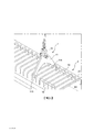
請參考圖2A及圖2B,其為本發明之使用第一較佳實施例吊裝裝置吊裝半預鑄梁之示意圖,其包含如下步驟:在步驟(a)中,如圖2A所示,裝設吊扣組件12於主體11;在步驟(b)中,如圖2A所示,懸吊吊扣組件12以將主體11移至半預鑄梁2之裸露的箍筋21處,使主體11之第一穿孔113及第二穿孔114略低於箍筋21之頂部;在步驟(c)中,如圖2B所示,分別穿置第一軸桿13及第二軸桿14於主體11之第一穿孔113及第二穿孔114,使第一軸桿113及第二軸桿114抵靠半預鑄梁2之箍筋21之內側接近角落處以支撐箍筋21。在本發明之實施例中,半預鑄梁2包括在其長軸R1方向以預定間隔排列之複數個呈現封閉之矩形狀的環狀箍筋21。在本發明之其他實施例中,半預鑄梁2包括一連續螺旋狀方箍筋或其他形狀之螺旋狀箍筋。Please refer to FIGS. 2A and 2B, which are schematic diagrams of using the hoisting device of the first preferred embodiment of the present invention to hoist a half beam, which includes the following steps: In step (a), as shown in FIG. 2A, install The sling assembly 12 is attached to the main body 11; in step (b), as shown in FIG. 2A, the sling assembly 12 is suspended to move the main body 11 to the exposed stirrup 21 of the half beam 2 so that the main body 11 is the first The perforation 113 and the second perforation 114 are slightly lower than the top of the stirrup 21; in step (c), as shown in FIG. 2B, the first shaft 13 and the second shaft 14 are respectively inserted through the first perforation of the main body 11 113 and the second through hole 114 make the first shaft 113 and the second shaft 114 abut against the inner side of the stirrup 21 of the half beam 2 near the corner to support the stirrup 21. In the embodiment of the present invention, the half beam 2 includes a plurality of closed rectangular ring stirrups 21 arranged at predetermined intervals in the direction of its long axis R1. In other embodiments of the present invention, the half beam 2 includes a continuous spiral square stirrup or spiral stirrups of other shapes.

請參考圖3及圖4A-4C,其顯示本發明之一第二較佳實施例吊裝裝置,其具有多個第一穿孔113'及第二穿孔114'之主體11'以適應不同尺寸,特別是不同寬度的半預鑄梁。主體11'之第一延伸臂111'包括複數個第一穿孔113',以供第一軸桿13可選擇性地穿置於複數個第一穿孔113'中之一者。主體11'之第二延伸臂112'包括複數個第二穿孔114',以供第二軸桿14可選擇性地穿置於複數個第二穿孔114'中之一者。第一延伸臂111'及第二延伸臂112'係沿水平方向朝兩側向外延伸,使主體11'之第一穿孔113'及複數個第二穿孔114'大致對齊,但與主體11'之第三穿孔115'不對齊。如圖3所示之實施例中,複數個第一穿孔113'及複數個第二穿孔114'大致位於同一水平高度,且低於第三穿孔115'。Please refer to FIGS. 3 and 4A-4C, which show a second preferred embodiment of the hoisting device of the present invention, which has a plurality of first through holes 113' and second through holes 114' of the main body 11' to adapt to different sizes, especially It is a half-beam of different widths. The first extension arm 111' of the main body 11' includes a plurality of first perforations 113' for the first shaft 13 to be selectively inserted into one of the plurality of first perforations 113'. The second extension arm 112' of the main body 11' includes a plurality of second perforations 114' for the second shaft 14 to be selectively inserted into one of the plurality of second perforations 114'. The first extension arm 111' and the second extension arm 112' extend horizontally to both sides outwards, so that the first perforation 113' and the plurality of second perforations 114' of the main body 11' are substantially aligned, but are aligned with the main body 11' The third perforation 115' is not aligned. In the embodiment shown in FIG. 3, the plurality of first perforations 113' and the plurality of second perforations 114' are approximately at the same level and lower than the third perforation 115'.

在本實施例中,使用主體11'吊裝半預鑄梁2之步驟(a)與步驟(b)與先前所述實施例大致相同。由於主體11'具有多個第一穿孔113'及第二穿孔114',在步驟(c)中,可選擇性地分別穿置第一軸桿13及第二軸桿14於不同位置的第一穿孔113'及第二穿孔114'中,使第一軸桿13及第二軸桿14可抵靠於不同寬度之半預鑄梁之箍筋21之內側的鄰近角落位置。如圖4A所示,第一軸桿13及第二軸桿14分別穿置於主體11'之最內側的第一穿孔113'及第二穿孔114'。如圖4B所示,第一軸桿13及第二軸桿14分別穿置於主體11'之中間位置的第一穿孔113'及第二穿孔114'。如圖4C所示,第一軸桿13及第二軸桿14分別穿置於主體11'之最外側的第一穿孔113'及第二穿孔114'。In this embodiment, the steps (a) and (b) of using the main body 11' to hoist the half-beam 2 are substantially the same as the previous embodiment. Since the main body 11' has a plurality of first through holes 113' and second through holes 114', in step (c), the first shaft 13 and the second shaft 14 can be selectively inserted into the first shaft 13 and the second shaft 14 in different positions. In the perforation 113' and the second perforation 114', the first shaft 13 and the second shaft 14 can abut the adjacent corners of the inner side of the stirrup 21 of the half-beam beams of different widths. As shown in FIG. 4A, the first shaft 13 and the second shaft 14 respectively pass through the first through hole 113' and the second through hole 114' on the innermost side of the main body 11'. As shown in FIG. 4B, the first shaft 13 and the second shaft 14 respectively pass through the first through hole 113' and the second through hole 114' in the middle of the main body 11'. As shown in FIG. 4C, the first shaft 13 and the second shaft 14 respectively pass through the first through hole 113' and the second through hole 114' on the outermost side of the main body 11'.

為防止軸桿在穿置於穿孔之後產生滑動,如圖5A及圖5B所示之第三較佳實施例中,第一軸桿13'進一步具有第一檔止部131'套置於其上及供第一插銷133'穿置之第一插銷孔132'於其中,而第二軸桿14'具有第二檔止部141'套置於其上及供第二插銷143'穿置之第二插銷孔142'於其中。在本發明之實施例中,第一檔止部131'及第二檔止部141'為環圈狀結構且其外徑大於主體11之第一穿孔113及第二穿孔114的直徑。另外,在將第一軸桿13'穿置於主體11之第一穿孔113及將第二軸桿14'穿置於主體11之第二穿孔114之步驟(c)中,如圖5A及圖5B所示,穿置第一軸桿13'於第一穿孔113,使第一軸桿13'之第一檔止部131'卡抵於主體11之第一側116之表面,且第一軸桿13'之第一插銷孔132'位於主體之第二側117,此時穿置第一插銷133'於第一插銷孔132'中,以防止第一軸桿13'滑動或脫落。同樣地,穿置第二軸桿14'於第二穿孔114,使第二軸桿14'之第二檔止部141'卡抵於主體11之第一側116之表面,且第二軸桿14'之第二插銷孔142'位於主體11之第二側117,此時穿置第二插銷143'於第二插銷孔142',以防止第二軸桿14'滑動或脫落。In order to prevent the shaft from sliding after being inserted into the perforation, in the third preferred embodiment shown in FIGS. 5A and 5B, the first shaft 13' further has a first stop portion 131' sleeved on it And the first pin hole 132' for the first pin 133' to pass through, and the second shaft 14' has a second stop portion 141' sleeved on it and the first pin hole 132' for the second pin 143' to pass through. There are two pin holes 142' therein. In the embodiment of the present invention, the first stop portion 131 ′ and the second stop portion 141 ′ have a ring-shaped structure and have an outer diameter larger than the diameter of the first through hole 113 and the second through hole 114 of the main body 11. In addition, in the step (c) of inserting the first shaft 13' into the first perforation 113 of the main body 11 and inserting the second shaft 14' into the second perforation 114 of the main body 11, as shown in FIGS. 5A and As shown in 5B, the first shaft 13' is inserted into the first through hole 113, so that the first stop portion 131' of the first shaft 13' is stuck to the surface of the first side 116 of the main body 11, and the first shaft The first pin hole 132' of the rod 13' is located on the second side 117 of the main body. At this time, the first pin 133' is inserted into the first pin hole 132' to prevent the first shaft 13' from sliding or falling off. Similarly, the second shaft 14' is inserted into the second through hole 114, so that the second stop portion 141' of the second shaft 14' is stuck against the surface of the first side 116 of the main body 11, and the second shaft The second pin hole 142' of 14' is located on the second side 117 of the main body 11. At this time, the second pin 143' is inserted into the second pin hole 142' to prevent the second shaft 14' from sliding or falling off.

圖6A-6F顯示本發明之第四較佳實施例,其中第一軸桿13''包括第一檔止部131''套設於其上及包括第一定位件134''及第三定位件135''於其上,其中第一定位件134''及第三定位件135''在第一軸桿13''之軸向R2方向上不對齊。第二軸桿14''包括第二檔止部141''套設於其上及包括第二定位件144''及第四定位件145''於其上,其中第二定位件144''及第四定位件145''在第二軸桿14''之軸向R2方向上不對齊。在本發明之一實施例中,第一定位件134''與第三定位件135''的位置在第一軸桿13''的周緣方向上大致相差1/4圓周,而第二定位件144''及第四定位件145''的位置在第二軸桿14''的周緣方向上大致相差1/4圓周。主體11''於鄰接於第一穿孔113''處設置有第一定位槽1131'以供第一軸桿13''之第一定位件134''及第三定位件135''分別穿過,且於鄰接於第二穿孔114'處設置有第二定位槽1141''以供第二軸桿14''之第二定位件144''及第四定位件145''分別穿過。6A-6F show the fourth preferred embodiment of the present invention, in which the first shaft 13" includes a first stop portion 131" sleeved thereon and includes a first positioning member 134" and a third positioning The member 135" is on it, wherein the first positioning member 134" and the third positioning member 135" are not aligned in the axial direction R2 of the first shaft 13". The second shaft 14" includes a second stopper 141" sleeved thereon, and includes a second positioning member 144" and a fourth positioning member 145" on it, wherein the second positioning member 144" And the fourth positioning member 145" is not aligned in the axial direction R2 of the second shaft 14". In an embodiment of the present invention, the positions of the first positioning member 134" and the third positioning member 135" are substantially different from each other by 1/4 of the circumference in the peripheral direction of the first shaft 13", and the second positioning member The positions of 144" and the fourth positioning member 145" are substantially different from each other by a quarter of a circle in the circumferential direction of the second shaft 14". The main body 11'' is provided with a first positioning groove 1131' adjacent to the first through hole 113'' for the first positioning member 134'' and the third positioning member 135'' of the first shaft 13'' to pass through, respectively , And a second positioning slot 1141" is provided adjacent to the second through hole 114' for the second positioning member 144" and the fourth positioning member 145" of the second shaft 14" to pass through.

請參考圖6A至圖6F。在此第四較佳實施例中,使用主體11''吊裝半預鑄梁2之步驟(a)與步驟(b)與先前所述實施例大致相同。在將第一軸桿13''穿置於主體11''之第一穿孔113''及將第二軸桿14''穿置於主體11''之第二穿孔114''之步驟(c)中,如圖6B所示,當穿置第一軸桿13''於該主體11''之第一穿孔113''中時,將第三定位件135''對準第一定位槽1131'';如圖6C所示,將第三定位件135''穿過第一定位槽1131';如圖6D所示,旋轉第一軸桿13''使第三定位件135''不對準第一定位槽1131'',同時將第一定位件134''對準第一定位槽1131'';如圖6E所示,將第一定位件134''穿過第一定位槽1131''後旋轉第一軸桿13''使第一定位件134''不對準第一定位槽1131',並使第一軸桿13''之第一檔止部131''卡抵於主體11'之一表面。同樣地,第二軸桿14''穿置第二穿孔114''之方式與第一軸桿13''穿置第一穿孔113''之方式相同。圖6F顯示第一軸桿13''及第二軸桿14''分別已穿置第一穿孔113''及第二穿孔114'完成組裝。在本發明之其他實施例中,亦可依需求調整第一軸桿13''及第二軸桿14''上定位件之數量,例如:第一軸桿13''僅設置第一定位件134''於其上,而第二軸桿14''僅設置第二定位件144''於其上。Please refer to Figure 6A to Figure 6F. In this fourth preferred embodiment, the steps (a) and (b) of using the main body 11" to hoist the half-beam 2 are substantially the same as the previous embodiments. In the step of inserting the first shaft 13'' into the first perforation 113'' of the main body 11'' and inserting the second shaft 14'' into the second perforation 114'' of the main body 11'' (c ), as shown in FIG. 6B, when the first shaft 13" is inserted into the first through hole 113" of the main body 11", the third positioning member 135" is aligned with the first positioning groove 1131 ''; As shown in Figure 6C, pass the third positioning member 135" through the first positioning slot 1131'; as shown in Figure 6D, rotate the first shaft 13" so that the third positioning member 135" is not aligned The first positioning groove 1131", while aligning the first positioning member 134" with the first positioning groove 1131"; as shown in FIG. 6E, the first positioning member 134" passes through the first positioning groove 1131" Rotate the first shaft 13" backwards so that the first positioning member 134" is not aligned with the first positioning groove 1131', and the first stop portion 131" of the first shaft 13" is locked against the main body 11' One surface. Similarly, the second shaft 14" penetrates the second through hole 114" in the same manner as the first shaft 13" penetrates the first through hole 113". FIG. 6F shows that the first shaft 13" and the second shaft 14" have respectively penetrated the first through hole 113" and the second through hole 114' to complete the assembly. In other embodiments of the present invention, the number of positioning elements on the first shaft 13" and the second shaft 14" can also be adjusted according to requirements, for example: the first shaft 13" is provided with only the first positioning element 134" is on it, and the second shaft 14" only has a second positioning member 144" on it.

請參考圖7A及圖7B。圖7A為本發明之第五較佳實施例顯示吊裝裝置之分解示意圖。圖7B為圖7A所示吊裝裝置組裝後之示意圖。主體11'''包括第一主件118'''及第二主件119'''。第一主件118'''包含一第一側1183'''、自該第一側1183'''圓滑過渡朝向該第二主件119'''之方向延伸之第二側1184''',並於其一近端具有第四穿孔1182''',以及於其一遠端具有第一穿孔113'''且在第一主件118'''之第一側1183'''具有第一抵固件1181'''設置於其上;第一側1183'''具有一平滑之曲度且第二側1184'''大致平直,第一側1183'''的長度大於第二側1184'''的長度。第二主件119'''包含一第一側1193'''、自該第一側1193'''圓滑過渡朝向該第一主件118'''之方向延伸之第二側1194''',並於其一近端具有第五穿孔1192''',以及於其一遠端具有第七穿孔1192b'''且在第二主件119'''之第一側1193'''具有第二抵固件1191'''設置於其上;第一側1193'''具有一平滑之曲度且第二側1194'''大致平直,第一側1193'''的長度大於第二側1194'''的長度。當第四穿孔1182'''對準並貼齊該第五穿孔1192'''時,則其形成相當於前述實施例中主體之第三穿孔,用以供吊扣組件12穿置。當支撐軸桿122穿置於卸扣121之穿孔1213、1214、第一主件118'''之第四穿孔1182'''及第二主件119'''之第五穿孔1192'''時,第一主件118'''之第二側1184'''相對於支撐軸桿122可滑動地抵靠於第二主件119'''之第二抵固件1191'''之一內側表面上,而第二主件119'''之第二側1194'''相對於支撐軸桿122可滑動地抵靠於第一主件118'''之第一抵固件1181'''之一內側表面上。在本發明之某些實施例中,在吊扣組件12穿置於主體11'''之第一主件118'''之第四穿孔1182'''及第二主件119'''之第五穿孔1192'''之後,將第一軸桿13穿置於主體11'''之第一主件118'''之第一穿孔113'''及將第二軸桿14穿置於主體11'''之第二主件119'''之第二穿孔114'''。在本發明之其他實施例中,可選擇如先前第三較佳實施例之第一軸桿13'及第二軸桿14',或是主體11'''之第一主件118'''在鄰接於第一穿孔113'''處及第二主件119'''在鄰接於第二穿孔114'''處亦可分別設置有如先前第四較佳實施例之第一定位槽1131''及第二定位槽1141'',用以穿置如先前第四較佳實施例實施例之第一軸桿13''及第二軸桿14''。除此之外,在本發明之其他實施例中,在吊扣組件12穿置於主體11'''之第一主件118'''之第四穿孔1182'''及第二主件119'''之第五穿孔1192'''之步驟前,可先將第一軸桿13穿置於主體11'''之第一主件118'''之第一穿孔113'''及將第二軸桿14穿置於主體11'''之第二主件119'''之第二穿孔114'''中。Please refer to Figure 7A and Figure 7B. Fig. 7A is an exploded schematic diagram showing the hoisting device according to the fifth preferred embodiment of the present invention. Fig. 7B is a schematic diagram of the hoisting device shown in Fig. 7A after being assembled. The main body 11'" includes a first main part 118'" and a second main part 119"'. The first main part 118''' includes a first side 1183''' and a second side 1184''' extending from the first side 1183''' to the direction of the second main part 119'''. , And has a fourth perforation 1182'" at one proximal end, and a first perforation 113"' at one distal end, and a first side 1183"' on the first side 1183"' of the first main member 118"" A retaining member 1181"' is arranged on it; the first side 1183"' has a smooth curvature and the second side 1184"' is approximately straight, and the length of the first side 1183"' is greater than that of the second side 1184''' length. The second main part 119''' includes a first side 1193''' and a second side 1194''' extending from the first side 1193''' to the direction of the first main part 118'''. , And has a fifth perforation 1192''' at one proximal end, and a seventh perforation 1192b''' at one distal end, and a first side 1193''' on the first side of the second main part 119''' The two retaining members 1191"' are arranged on it; the first side 1193"' has a smooth curvature and the second side 1194"' is approximately straight, and the length of the first side 1193"' is greater than that of the second side 1194''' length. When the fourth perforation 1182"' is aligned with and aligned with the fifth perforation 1192"', it forms the third perforation equivalent to the main body in the foregoing embodiment for the buckle assembly 12 to pass through. When the support shaft 122 passes through the perforations 1213 and 1214 of the shackle 121, the fourth perforation 1182''' of the first main part 118''' and the fifth perforation 1192''' of the second main part 119''' When, the second side 1184''' of the first main member 118"' slidably abuts against the inner side of one of the second abutment members 1191"' of the second main member 119"' relative to the supporting shaft 122 On the surface, the second side 1194'” of the second main member 119'" slidably abuts against the first abutment member 1181"' of the first main member 118"' with respect to the support shaft 122 One on the inside surface. In some embodiments of the present invention, the hanging buckle assembly 12 passes through the fourth perforation 1182''' of the first main part 118''' of the main body 11''' and the fourth hole 1182''' of the second main part 119'''. After five perforations 1192"', the first shaft 13 is inserted into the first main part 118"' of the main body 11"' through the first perforation 113"' and the second shaft 14 is inserted into the main body 11'"The second main part 119'"The second perforation 114'". In other embodiments of the present invention, the first shaft 13' and the second shaft 14' of the previous third preferred embodiment can be selected, or the first main part 118"' of the main body 11"' Adjacent to the first perforation 113''' and the second main part 119''' to the second perforation 114''' can also be respectively provided with the first positioning groove 1131' as in the previous fourth preferred embodiment. 'And the second positioning groove 1141", used to pass through the first shaft 13" and the second shaft 14" as in the previous fourth preferred embodiment. In addition, in other embodiments of the present invention, the hanging buckle assembly 12 passes through the fourth perforation 1182"' of the first main part 118"' of the main body 11"' and the second main part 119' Before the step of''the fifth perforation 1192''', the first shaft 13 can be inserted into the first perforation 113''' of the first main part 118''' of the main body 11''' and the The second shaft 14 penetrates into the second perforation 114"' of the second main part 119"' of the main body 11'".

本文中的用語「一」或「一種」係用以敘述本創作之元件及成分。此術語僅為了敘述方便及給予本創作之基本觀念。此敘述應被理解為包括一種或至少一種,且除非明顯地另有所指,表示單數時亦包括複數。於申請專利範圍中和「包含」一詞一起使用時,該用語「一」可意謂一個或超過一個。此外,本文中的用語「或」其意同「及/或」。The term "one" or "one" in this article is used to describe the elements and components of this creation. This term is only for the convenience of description and to give the basic idea of this creation. This description should be understood to include one or at least one, and unless clearly indicated otherwise, the singular number also includes the plural number. When used with the word "include" in the scope of patent application, the term "one" can mean one or more than one. In addition, the term "or" in this article means the same as "and/or".

除非另外規定,否則諸如「上方」、「下方」、「向上」、「左邊」、「右邊」、「向下」、「本體」、「底座」、「垂直」、「水平」、「側」、「較高」、「下部」、「上部」、「上方」、「下面」等空間描述係關於圖中所展示之方向加以指示。應理解,本文中所使用之空間描述僅出於說明之目的,且本文中所描述之結構之實際實施可以任何相對方向在空間上配置,此限制條件不會改變本發明實施例之優點。舉例來說,在一些實施例之描述中,提供「在」另一元件「上」之一元件可涵蓋前一元件直接在後一元件上(例如,與後一元件實體接觸)的狀況以及一或複數個介入元件位於前一元件與後一元件之間的狀況。Unless otherwise specified, such as "above", "below", "up", "left", "right", "down", "body", "base", "vertical", "horizontal", "side" , "Higher", "Lower", "Upper", "Above", "Below" and other space descriptions indicate the directions shown in the figure. It should be understood that the spatial description used herein is only for illustrative purposes, and the actual implementation of the structure described herein can be spatially arranged in any relative direction, and this restriction will not change the advantages of the embodiments of the present invention. For example, in the description of some embodiments, providing an element "on" another element may cover the situation where the previous element is directly on the next element (for example, physically contacting the next element) and a Or a situation where a plurality of intervening elements are located between the previous element and the next element.

如本文中所使用,術語「大致」、「實質上」、「實質的」及「約」用以描述及考慮微小之變化。當與事件或情形結合使用時,該些術語可意指事件或情形明確發生之情況以及事件或情形極近似於發生之情況。As used herein, the terms "approximately", "substantially", "substantial" and "about" are used to describe and consider minor changes. When used in conjunction with an event or situation, these terms can mean a situation in which the event or situation clearly occurs and an event or situation that closely approximates the situation in which it occurred.

以上所述之實施例僅係為說明本創作之技術思想及特點,其目的在使熟習此項技藝之人士能夠瞭解本創作之內容並據以實施,當不能以之限定本創作之專利範圍,依本創作所揭示之精神所作之均等變化或修飾,仍應涵蓋在本創作之專利範圍內。The above-mentioned embodiments are only to illustrate the technical ideas and characteristics of this creation, and their purpose is to enable those who are familiar with the art to understand the content of this creation and implement them accordingly. When they cannot be used to limit the patent scope of this creation, Equal changes or modifications made in accordance with the spirit of this creation should still be covered by the scope of the patent of this creation.

1              吊裝裝置 2              半預鑄梁 11            主體 11'           主體 11''           主體 11'''          主體 12            吊扣組件 13            第一軸桿 13'           第一軸桿 13''           第一軸桿 14            第二軸桿 14'           第二軸桿 14''           第二軸桿 21            箍筋 111           第一延伸臂 111'          第一延伸臂 111''         第一延伸臂 112          第二延伸臂 112'          第二延伸臂 112''         第二延伸臂 113          第一穿孔 113'          第一穿孔 113''         第一穿孔 113'''        第一穿孔 114          第二穿孔 114'          第二穿孔 114''         第二穿孔 114'''        第二穿孔 115          第三穿孔 115'          第三穿孔 115''         第三穿孔 115'''        第三穿孔 116          第一側 116'          第一側 116''         第一側 117          第二側 117'          第二側 117''         第二側 118'''        第一主件 119'''        第二主件 121          卸扣 122          支撐軸桿 122a         第一端 122b         第二端 123          緊固件 131'          第一檔止部 131''         第一檔止部 132'          第一插銷孔 133'          第一插銷 134''         第一定位件 135''         第三定位件 141'          第二檔止部 141''         第二檔止部 142'          第二插銷孔 143'          第二插銷 144''         第二定位件 145''         第四定位件 1111         遠端部 1121         遠端部 1131'        第一定位槽 1141'        第二定位槽 1181'''      第一抵固件 1182'''      第四穿孔 1183'''      第一側 1184'''      第二側 1191'''      第二抵固件 1192'''      第五穿孔 1193'''      第一側 1194'''      第二側 1211         端部 1212         端部 1213         穿孔 1214         穿孔 A1           軸線 R1            長軸 R2            軸向 θ              夾角 1 Lifting device 2 Half-beam 11 Subject 11' Subject 11'' Subject 11''' Subject 12 Hanging buckle assembly 13 First shaft 13' First shaft 13'' First shaft 14 Second shaft 14' Second shaft 14'' Second shaft 21 Stirrups 111 First extension arm 111' First extension arm 111'' First extension arm 112 Second extension arm 112' Second extension arm 112'' Second extension arm 113 First punch 113' First punch 113'' First hole 113''' The first hole 114 Second hole 114' Second hole 114'' Second hole 114''' Second hole 115 Third hole 115' The third hole 115'' Third hole 115''' The third hole 116 First side 116' First side 116'' First side 117 Second side 117' second side 117'' Second side 118''' The first main part 119''' The second main part 121 Shackle 122 Support shaft 122a First end 122b Second end 123 Fasteners 131' First stop 131'' First gear stop 132' The first pin hole 133' First bolt 134'' The first positioning piece 135'' Third positioning piece 141' The second stop 141'' Second gear stop 142' The second pin hole 143' Second latch 144'' The second positioning piece 145'' Fourth positioning piece 1111 Remote department 1121 Remote part 1131' The first positioning slot 1141' The second positioning slot 1181''' First arrival firmware 1182''' Fourth perforation 1183''' The first side 1184''' second side 1191''' The second firmware 1192''' Fifth perforation 1193''' The first side 1194''' second side 1211 End 1212 End 1213 Piercing 1214 Piercing A1 Axis R1 Long axis R2 Axial θ Included angle

以下所描述的附圖僅是出於示例性目的,並非欲以任何方式限制本揭露之範疇: 圖1A為本發明之第一較佳實施例之吊裝裝置之分解示意圖。 圖1B為圖1A所示吊裝裝置組裝後之示意圖。 圖2A為本發明之第一較佳實施例顯示使用吊裝裝置吊裝半預鑄梁之示意圖之一。 圖2B為本發明之第一較佳實施例顯示使用吊裝裝置吊裝半預鑄梁之示意圖之二。 圖3為本發明之第二較佳實施例顯示具有多個第一穿孔及第二穿孔之吊裝裝置的主體之示意圖。 圖4A為本發明之第二較佳實施例中軸桿穿置於最內側穿孔位置之示意圖。 圖4B為本發明之第二較佳實施例中軸桿穿置於中央穿孔位置之示意圖。 圖4C為本發明之第二較佳實施例中軸桿穿置於最外側穿孔位置之示意圖。 圖5A為本發明之第三較佳實施例之吊裝裝置之分解示意圖。 圖5B為圖5A所示吊裝裝置組裝後之示意圖。 圖6A為本發明之第四較佳實施例之吊裝裝置之分解示意圖。 圖6B為圖6A之吊裝裝置的局部放大圖。 圖6C為本發明第四較佳實施例顯示軸桿之一定位件穿越吊裝裝置穿孔之示意圖。 圖6D為本發明之第四實施例顯示軸桿之另一定位件對準但尚未穿越吊裝裝置穿孔之示意圖。 圖6E為本發明之第四實施例顯示軸桿之兩定位件均穿越吊裝裝置穿孔之示意圖。 圖6F為圖6A所示吊裝裝置組裝後之示意圖。 圖7A為本發明之第五較佳實施例之吊裝裝置之分解示意圖。 圖7B為圖7A所示吊裝裝置組裝後之示意圖。 The drawings described below are only for exemplary purposes, and are not intended to limit the scope of the disclosure in any way: Fig. 1A is an exploded schematic view of the hoisting device of the first preferred embodiment of the present invention. Fig. 1B is a schematic diagram of the hoisting device shown in Fig. 1A after being assembled. 2A is one of the schematic diagrams showing the use of the hoisting device to hoist a semi-beam beam according to the first preferred embodiment of the present invention. 2B is the second schematic diagram of the first preferred embodiment of the present invention showing the use of the hoisting device to hoist the half beam. 3 is a schematic diagram showing the main body of the hoisting device with a plurality of first through holes and second through holes according to the second preferred embodiment of the present invention. Fig. 4A is a schematic diagram of the shaft inserted in the innermost perforation position in the second preferred embodiment of the present invention. Fig. 4B is a schematic diagram of the shaft passing through the central hole in the second preferred embodiment of the present invention. Fig. 4C is a schematic diagram of the shaft passing through the outermost perforation position in the second preferred embodiment of the present invention. Fig. 5A is an exploded schematic view of the hoisting device of the third preferred embodiment of the present invention. Fig. 5B is a schematic diagram of the hoisting device shown in Fig. 5A after being assembled. Fig. 6A is an exploded schematic view of the hoisting device of the fourth preferred embodiment of the present invention. Fig. 6B is a partial enlarged view of the lifting device of Fig. 6A. 6C is a schematic diagram showing a positioning member of a shaft passing through a hole of the hoisting device according to the fourth preferred embodiment of the present invention. 6D is a schematic diagram of the fourth embodiment of the present invention showing that another positioning member of the shaft is aligned but has not passed through the hole of the hoisting device. 6E is a schematic diagram of the fourth embodiment of the present invention showing that both positioning members of the shaft pass through the holes of the hoisting device. Fig. 6F is a schematic diagram of the lifting device shown in Fig. 6A after being assembled. Fig. 7A is an exploded schematic diagram of the hoisting device of the fifth preferred embodiment of the present invention. Fig. 7B is a schematic diagram of the hoisting device shown in Fig. 7A after being assembled.

1              吊裝裝置 11            主體 12            吊扣組件 13            第一軸桿 14            第二軸桿 111           第一延伸臂 112          第二延伸臂 113          第一穿孔 114          第二穿孔 115          第三穿孔 121          卸扣 122          支撐軸桿 122a         第一端 122b         第二端 123          緊固件 1111         遠端部 1121         遠端部 1211         端部 1212         端部 1213         穿孔 1214         穿孔 A1           軸線 θ              夾角 1 Lifting device 11 Subject 12 Hanging buckle assembly 13 First shaft 14 Second shaft 111 First extension arm 112 Second extension arm 113 First punch 114 Second hole 115 Third hole 121 Shackle 122 Support shaft 122a First end 122b Second end 123 Fasteners 1111 Remote department 1121 Remote part 1211 End 1212 End 1213 Piercing 1214 Piercing A1 Axis θ Included angle

Claims (26)

一種用於吊裝半預鑄梁之吊裝裝置,該半預鑄梁包括在該半預鑄梁之一長軸方向以一預定間隔排列之複數個環狀箍筋或一連續螺旋狀箍筋,該吊裝裝置包括:一主體,其相對於一軸線對稱配置,且包括一第一穿孔、一第二穿孔及一第三穿孔,其中該軸線穿過該第三穿孔且該第一穿孔與該第二穿孔相對於該軸線對稱配置;一吊扣組件,其為封閉圈狀結構,並穿置於該第三穿孔中;一第一軸桿,其穿置於該主體之該第一穿孔中;一第二軸桿,其穿置於該主體之該第二穿孔中,其中當該吊裝裝置用以吊裝該半預鑄梁時,該吊裝裝置之該第一軸桿及該第二軸桿抵靠該半預鑄梁之該複數個環狀箍筋或該連續螺旋狀箍筋之一部分箍筋的內側。 A hoisting device for hoisting a half-beam. The half-beam comprises a plurality of annular stirrups or a continuous spiral stirrup arranged at a predetermined interval in the direction of a long axis of the half-beam. The hoisting device includes: a main body, which is symmetrically arranged with respect to an axis, and includes a first through hole, a second through hole, and a third through hole, wherein the axis passes through the third through hole and the first through hole and the second through hole The perforations are arranged symmetrically with respect to the axis; a buckle assembly, which is a closed loop structure, and is inserted in the third perforation; a first shaft is inserted in the first perforation of the main body; Two shafts, which pass through the second perforation of the main body, wherein when the hoisting device is used for hoisting the half beam, the first shaft and the second shaft of the hoisting device abut against the The inner side of the plurality of annular stirrups or a part of the continuous spiral stirrups of the half beam. 如請求項1之吊裝裝置,其中該封閉圈狀結構包括兩端具有穿孔之一卸扣及一支撐軸桿,該支撐軸桿穿置於該卸扣之兩端部之穿孔中並可旋轉地穿置於該主體之該第三穿孔中。 Such as the hoisting device of claim 1, wherein the closed ring structure includes a shackle with perforations at both ends and a support shaft, the support shaft is inserted into the perforations at both ends of the shackle and can rotate Put in the third perforation of the main body. 如請求項2之吊裝裝置,其中該第一軸桿包含一第一定位件於其上且該第二軸桿包含一第二定位件於其上,該主體於鄰接於該第一穿孔處設置有一第一定位槽,供該第一軸桿之該第一定位件穿過,且其中該主體於鄰接於該第二穿孔處設置有一第二定位槽,供該該第二軸桿之該第二定位件 穿過。 Such as the hoisting device of claim 2, wherein the first shaft includes a first positioning member thereon and the second shaft includes a second positioning member thereon, and the main body is disposed adjacent to the first perforation There is a first positioning groove for the first positioning member of the first shaft to pass through, and wherein the main body is provided with a second positioning groove adjacent to the second through hole for the second positioning of the second shaft. Two positioning parts Through. 如請求項3之吊裝裝置,其中該第一軸桿設置有一第一檔止部於其上,當該第一軸桿穿置於該主體之該第一穿孔時,該第一定位件位於該主體之一第一側,而該第一檔止部位於該主體之相對於該第一側之一第二側,藉此該第一檔止部卡抵於該主體之一表面,且其中該第二軸桿設置有一第二檔止部,當該第二軸桿穿置於該主體之該第二穿孔時,該第二定位件位於該主體之該第一側,而該第二檔止部位於該第主體之相對於該第二側,藉此該第二檔止部卡抵於該主體之該表面。 For example, the hoisting device of claim 3, wherein the first shaft is provided with a first stop portion, and when the first shaft passes through the first perforation of the main body, the first positioning member is located at the A first side of the main body, and the first stop is located on a second side of the main body opposite to the first side, whereby the first stop is clamped against a surface of the main body, and wherein the The second shaft is provided with a second stopper. When the second shaft passes through the second through hole of the main body, the second positioning member is located on the first side of the main body, and the second stopper The portion is located on the second side of the first main body, whereby the second stop portion is clamped against the surface of the main body. 如請求項4之吊裝裝置,其中該第一軸桿進一步設置有一第三定位件於其上且該第二軸桿進一步設置有一第四定位件於其上,該第三定位件與該第一定位件於該第一軸桿之軸向方向上不對齊,且該第四定位件與該第二定位件於該第二軸桿之軸向方向上不對齊,其中當第一軸桿穿置於該第一穿孔時,該第三定位件先通過該第一定位槽,而後該第一定位件再通過該第一定位槽,使該第一定位件及該第三定位件皆位於該主體之該第一側,當第二軸桿穿置於該第二穿孔時,該第四定位件先穿過該第二定位槽,而後該第二定位件再穿過該該第二定位槽,使該第二定位件及該第四定位件皆位於該主體之該第一側。 For example, the lifting device of claim 4, wherein the first shaft is further provided with a third positioning member thereon and the second shaft is further provided with a fourth positioning member thereon, the third positioning member and the first The positioning member is not aligned in the axial direction of the first shaft, and the fourth positioning member and the second positioning member are not aligned in the axial direction of the second shaft, wherein when the first shaft passes through During the first perforation, the third positioning element first passes through the first positioning groove, and then the first positioning element passes through the first positioning groove, so that the first positioning element and the third positioning element are both located on the main body On the first side, when the second shaft passes through the second through hole, the fourth positioning member first passes through the second positioning groove, and then the second positioning member passes through the second positioning groove, Both the second positioning member and the fourth positioning member are located on the first side of the main body. 如請求項1之吊裝裝置,其中該主體包括朝兩側向外延伸之一第一延伸臂及一第二延伸臂,該第一穿孔及該第二穿孔分別位於該第一延伸臂及該第二延伸臂中。 For example, the hoisting device of claim 1, wherein the main body includes a first extension arm and a second extension arm that extend outward to both sides, and the first through hole and the second through hole are respectively located at the first extension arm and the first extension arm. Two extension arms. 如請求項1之吊裝裝置,其中該第一軸桿具有一第一檔止部於其上、一第一插銷孔於其中以及一第一插銷,當該第一軸桿穿置於該主體之該第一穿孔中時,該第一插銷孔位於該主體之一第一側且該第一插銷穿置於該第一插銷孔中,該第一檔止部位於該主體之相對於該第一側之一第二側以卡抵於該主體之一面,且其中該第二軸桿設置有一第二檔止部於其上、一第二插銷孔於其中以及一第二插銷,當該第二軸桿穿置於該主體之該該第二穿孔時,該第二插銷孔位於該主體之該第一側且該第二插銷穿置於該第二插銷孔中,該第二檔止部位於該主體之該第二側以卡抵於該主體之該面。 Such as the hoisting device of claim 1, wherein the first shaft has a first stop portion thereon, a first pin hole in it, and a first pin, when the first shaft passes through the main body When the first through hole is in the first hole, the first plug hole is located on a first side of the main body and the first plug is inserted into the first plug hole, and the first stop portion is located on the main body relative to the first A second side of the side is snapped against a surface of the main body, and the second shaft is provided with a second stopper on it, a second pin hole in it, and a second pin. When the second When the shaft is inserted into the second through hole of the main body, the second pin hole is located on the first side of the main body and the second pin is inserted into the second pin hole, and the second stop is located The second side of the main body is snapped against the surface of the main body. 如請求項1之吊裝裝置,其中該主體設置有複數個第一穿孔及複數個第二穿孔,藉此該第一軸桿可選擇地穿置於該複數個第一穿孔之一者,且該第二軸桿可選擇地穿置於該複數個第二穿孔之一者。 For example, the lifting device of claim 1, wherein the main body is provided with a plurality of first perforations and a plurality of second perforations, whereby the first shaft can be selectively inserted into one of the plurality of first perforations, and the The second shaft can optionally pass through one of the plurality of second perforations. 如請求項8之吊裝裝置,其中該複數個第一穿孔以及該複數個第二穿孔大致對齊,且該第三穿孔與該複數個第一穿孔或該複數個第二穿孔並不對齊。 Such as the lifting device of claim 8, wherein the plurality of first perforations and the plurality of second perforations are substantially aligned, and the third perforation is not aligned with the plurality of first perforations or the plurality of second perforations. 一種吊裝裝置,其包括:一主體,其相對於一軸線對稱配置,且包括一第一穿孔、一第二穿孔及一第三穿孔;一吊扣組件,其包括一卸扣及一支撐軸桿,該支撐軸桿穿置於該卸 扣及該主體之該第三穿孔,使該吊扣組件可活動軸接於該主體;一第一軸桿,其穿置於該主體之該第一穿孔;及一第二軸桿,其穿置於該主體之該第二穿孔;其中該第一軸桿及第二軸桿用以抵靠以及支撐欲吊裝的物體的複數個環狀或連續螺旋狀結構的內側。 A hoisting device includes: a main body, which is symmetrically arranged with respect to an axis, and includes a first perforation, a second perforation, and a third perforation; a hanging buckle assembly, which includes a shackle and a support shaft, The support shaft is put on the unloading The buckle and the third perforation of the main body enable the buckle assembly to be movably connected to the main body; a first shaft that penetrates the first perforation of the main body; and a second shaft that penetrates The second perforation in the main body; wherein the first shaft and the second shaft are used to abut against and support the inner side of a plurality of annular or continuous spiral structures of the object to be hoisted. 如請求項10之吊裝裝置,其中該第一穿孔與該第二穿孔大致位於同一水平高度且低於該第三穿孔。 Such as the hoisting device of claim 10, wherein the first perforation and the second perforation are approximately at the same level and lower than the third perforation. 如請求項11之吊裝裝置,其中該主體於鄰接於該第一穿孔處設置有一第一定位槽,以供該第一軸桿之一第一定位件穿過,且其中該主體於鄰接於該第二穿孔設置處有一第二定位槽,以供該該第二軸桿之一第二定位件穿過。 For example, the lifting device of claim 11, wherein the main body is provided with a first positioning slot adjacent to the first through hole for a first positioning member of the first shaft to pass through, and wherein the main body is adjacent to the A second positioning slot is provided at the second perforation for passing through a second positioning member of the second shaft. 如請求項12之吊裝裝置,其中該第一軸桿設置有一第一檔止部於其上,當該第一軸桿穿置於該主體之該第一穿孔時,該第一定位件位於該主體之一第一側,而該第一檔止部位於該第主體之相對於該第一側之一第二側,藉此該第一檔止部卡抵於該主體之一表面,且其中該第二軸桿設置有一第二檔止部,當該第二軸桿穿置於該主體之該第二穿孔時,該第二定位件位於該主體之該第一側,而該第二檔止部位於該第主體之相對於該第二側,藉此該第二檔止部卡抵於該主體之該表面。 For example, the hoisting device of claim 12, wherein the first shaft is provided with a first stop portion, and when the first shaft passes through the first perforation of the main body, the first positioning member is located at the A first side of the main body, and the first stop is located on a second side of the first main body opposite to the first side, whereby the first stop is clamped against a surface of the main body, and wherein The second shaft is provided with a second stop portion. When the second shaft passes through the second through hole of the main body, the second positioning member is located on the first side of the main body, and the second stop The stop portion is located on the second side of the first main body, so that the second stop portion is clamped against the surface of the main body. 如請求項13之吊裝裝置,其中該第一軸桿進一步設置有一第三定位 件於其上且該第二軸桿進一步設置有一第四定位件於其上,該第三定位件與該第一定位件於該第一軸桿之軸向方向上不對齊,且該第四定位件與該第二定位件於該第二軸桿之軸向方向上不對齊,其中當第一軸桿穿置於該第一穿孔時,該第三定位件先通過該第一定位槽,而後該第一定位件再通過該第一定位槽,使該第一定位件及該第三定位件皆位於該主體之該第一側,當第二軸桿穿置於該第二穿孔時,該第四定位件先穿過該第二定位槽,而後該第二定位件再穿過該該第二定位槽,使該第二定位件及該第四定位件皆位於該主體之該第一側。 Such as the hoisting device of claim 13, wherein the first shaft is further provided with a third positioning And the second shaft is further provided with a fourth positioning part thereon, the third positioning part and the first positioning part are not aligned in the axial direction of the first shaft, and the fourth positioning part is not aligned with the first positioning part in the axial direction of the first shaft. The positioning member and the second positioning member are not aligned in the axial direction of the second shaft, wherein when the first shaft passes through the first through hole, the third positioning member first passes through the first positioning groove, Then, the first positioning member passes through the first positioning slot, so that the first positioning member and the third positioning member are both located on the first side of the main body. When the second shaft is inserted into the second perforation, The fourth positioning element first passes through the second positioning groove, and then the second positioning element passes through the second positioning groove, so that the second positioning element and the fourth positioning element are both located at the first position of the main body. side. 如請求項10之吊裝裝置,其中該主體包括朝兩側向外延伸之一第一延伸臂及一第二延伸臂,該第一穿孔及該第二穿孔分別位於該第一延伸臂及該第二延伸臂中。 For example, the hoisting device of claim 10, wherein the main body includes a first extension arm and a second extension arm that extend outward to both sides, and the first through hole and the second through hole are located at the first extension arm and the first extension arm, respectively. Two extension arms. 如請求項10之吊裝裝置,其中該第一軸桿具有一第一檔止部於其上、一第一插銷孔於其中以及一第一插銷,當該第一軸桿穿置於該主體之該第一穿孔中時,該第一插銷孔位於該主體之一第一側且該第一插銷穿置於該第一插銷孔中,該第一檔止部位於該主體之相對於該第一側之一第二側以卡抵於該主體之一面,且其中該第二軸桿設置有一第二檔止部於其上、一第二插銷孔於其中以及一第二插銷,當該第二軸桿穿置於該主體之該該第二穿孔時,該第二插銷孔位於該主體之該第一側且該第二插銷穿置於該第二插銷孔中,該第二檔止部位於該主體之該第二側以卡抵於該主體之該面。 For example, the lifting device of claim 10, wherein the first shaft has a first stop portion on it, a first pin hole in it, and a first pin, when the first shaft passes through the main body When the first through hole is in the first hole, the first plug hole is located on a first side of the main body and the first plug is inserted into the first plug hole, and the first stop portion is located on the main body relative to the first One side of the second side is snapped against a surface of the main body, and the second shaft is provided with a second stopper on it, a second pin hole in it, and a second pin. When the second shaft When the shaft is inserted into the second through hole of the main body, the second pin hole is located on the first side of the main body and the second pin is inserted into the second pin hole, and the second stop is located The second side of the main body is snapped against the surface of the main body. 如請求項10之吊裝裝置,其中該主體設置有複數個第一穿孔及複數個第二穿孔,藉此該第一軸桿可選擇地穿置於該複數個第一穿孔之一者,且該第二軸桿可選擇地穿置於該複數個第二穿孔之一者。 For example, the lifting device of claim 10, wherein the main body is provided with a plurality of first perforations and a plurality of second perforations, whereby the first shaft can be selectively inserted into one of the plurality of first perforations, and the The second shaft can optionally pass through one of the plurality of second perforations. 如請求項17之吊裝裝置,其中該複數個第一穿孔以及該複數個第二穿孔大致對齊,且該第三穿孔與該複數個第一穿孔或該複數個第二穿孔並不對齊。 For example, the lifting device of claim 17, wherein the plurality of first perforations and the plurality of second perforations are substantially aligned, and the third perforation is not aligned with the plurality of first perforations or the plurality of second perforations. 如請求項17之吊裝裝置,其中該主體包括一第一主件及一第二主件,該第一主件具有一第一側以及自該第一側圓滑過渡朝向該第二主件之方向延伸之第二側,以及位於一近端之一第四穿孔且在該第一主件之一第一側具有一第一抵固件設置於其上,該第二主件具有一第一側以及自該第一側圓滑過渡朝向該第一主件之方向延伸之第二側,以及位於一近端之一第五穿孔且在該第二主件之一第一側具有一第二抵固件設置於其上,該第四穿孔對準並貼合該第五穿孔以形成該主體之該第三穿孔,且其中當該支撐軸桿穿置於該卸扣之該等穿孔及該主體之該第三穿孔中時,該第一主件之該第二側相對於該支撐軸桿可滑動地抵靠於該第二主件之該第二抵固件一內側表面,而該第二主件之該第二側相對於該支撐軸桿可滑動地抵靠於該第一主件之該第一抵固件一內側表面。 Such as the hoisting device of claim 17, wherein the main body includes a first main part and a second main part, the first main part has a first side and a smooth transition from the first side to the second main part The second side of the extension, and a fourth through hole located at a proximal end, and a first abutment member is provided on a first side of the first main part, the second main part has a first side and A second side extending smoothly from the first side toward the direction of the first main member, and a fifth perforation located at a proximal end with a second abutting member on a first side of the second main member On it, the fourth perforation is aligned with and attached to the fifth perforation to form the third perforation of the main body, and when the support shaft passes through the perforations of the shackle and the first perforation of the main body In the three through-holes, the second side of the first main part slidably abuts against an inner surface of the second abutment member of the second main part relative to the support shaft, and the second main part of the second main part The second side slidably abuts against an inner surface of the first retaining member of the first main component relative to the supporting shaft. 一種吊裝半預鑄梁之方法,其包括:(a)裝設一吊扣組件於一主體;(b)懸吊該吊扣組件以將該主體移至一半預鑄梁之裸露的箍筋處,使該 主體之一第一穿孔及一第二穿孔略低於該等箍筋;(c)分別穿置一第一軸桿及一第二軸桿於該主體之該第一穿孔及該第二穿孔,使該第一軸桿及該第二軸桿抵靠該等箍筋的內側。 A method for hoisting a half-beam, which includes: (a) installing a sling assembly on a main body; (b) suspending the sling assembly to move the main body to half of the skein's exposed stirrups, so that The A first perforation and a second perforation of the main body are slightly lower than the stirrups; (c) a first shaft and a second shaft are respectively inserted through the first perforation and the second perforation of the main body, The first shaft and the second shaft are abutted against the inner side of the stirrups. 如請求項20之方法,其中在步驟(c)中,將該第一軸桿之一第一定位件對準該第一穿孔之一第一定位槽,將該第一定位件穿過該第一定位槽後旋轉該第一軸桿使該第一定位件不對準該第一定位槽,將該第一軸桿之一第一檔止部卡抵於該主體之一面;及將該第二軸桿之一第二定位件對準該第二穿孔之一第二定位槽,將該第二定位件穿過該第二定位槽後旋轉該第二軸桿使該第二定位件不對準該第二定位槽,將該第二軸桿之一第二檔止部卡抵於該主體之該面。 Such as the method of claim 20, wherein in step (c), a first positioning member of the first shaft is aligned with a first positioning groove of the first perforation, and the first positioning member passes through the first positioning member After a positioning groove, rotate the first shaft so that the first positioning member does not align with the first positioning groove, and snap a first stop portion of the first shaft against a surface of the main body; and A second positioning member of the shaft is aligned with a second positioning groove of the second perforation, the second positioning member is passed through the second positioning groove, and then the second shaft is rotated so that the second positioning member is not aligned with the second positioning member. The second positioning groove clamps a second stop portion of the second shaft against the surface of the main body. 如請求項20之方法,其中在步驟(c)中,將該第一軸桿之一第三定位件對準該第一穿孔之一第一定位槽,將該第三定位件穿過該第一定位槽後旋轉該第一軸桿使該第三定位件不對準該第一定位槽,再將該第一軸桿之一第一定位件對準該第一穿孔之該第一定位槽,將該第一定位件穿過該第一定位槽後旋轉該第一軸桿使該第一定位件不對準該第一定位槽,將該第一軸桿之一第一檔止部卡抵於該主體之一面;及將該第二軸桿之一第四定位件對準該第二穿孔之一第二定位槽,將該第四定位件穿過該第二定位槽後旋轉該第二軸桿使該第四定位件不對準該第二定位槽,再將該第二軸桿之一第二定位件對準該第二穿孔之該第二定位槽,將該第二定位件穿過該第二定位槽後旋轉該第二軸桿使該第二定位件不對準該第二定位槽,將該第二軸桿之一第二檔止部卡抵於該主體之該面。 Such as the method of claim 20, wherein in step (c), a third positioning member of the first shaft is aligned with a first positioning groove of the first perforation, and the third positioning member is passed through the first positioning groove. Rotate the first shaft to make the third positioning member not align with the first positioning groove after a positioning groove, and then align a first positioning member of the first shaft with the first positioning groove of the first through hole, After passing the first positioning member through the first positioning groove, rotate the first shaft so that the first positioning member does not align with the first positioning groove, and a first stop portion of the first shaft is clamped against A surface of the main body; and a fourth positioning member of the second shaft is aligned with a second positioning groove of the second perforation, the fourth positioning member passes through the second positioning groove and then the second shaft is rotated The rod makes the fourth positioning member not aligned with the second positioning groove, and then one of the second positioning members of the second shaft rod is aligned with the second positioning groove of the second through hole, and the second positioning member passes through the After the second positioning slot, the second shaft is rotated to make the second positioning member not aligned with the second positioning slot, and a second stop portion of the second shaft is clamped against the surface of the main body. 如請求項20之方法,其中在步驟(c)中,穿置該第一軸桿於該第一穿孔,使該第一軸桿之一第一檔止部卡抵於該主體之一面而該第一軸桿之一第一插銷孔位於該主體之另一面,穿置一第一插銷於該第一插銷孔;及穿置該第二軸桿於該第二穿孔,使該第二軸桿之一第二檔止部卡抵於該主體之該面而該第二軸桿之一第二插銷孔位於該主體之該另一面,穿置一第二插銷於該第二插銷孔。 Such as the method of claim 20, wherein in step (c), the first shaft is inserted through the first through hole, so that a first stop portion of the first shaft is clamped against a surface of the main body and the A first pin hole of the first shaft is located on the other side of the main body, and a first pin is inserted into the first pin hole; and the second shaft is inserted into the second hole to make the second shaft A second stop portion is clamped against the surface of the main body, and a second pin hole of the second shaft is located on the other surface of the main body, and a second pin is inserted through the second pin hole. 一種吊裝半預鑄梁之方法,其包括:(a)裝設一吊扣組件於一主體;(b)懸吊該吊扣組件以將該主體移至一半預鑄梁之裸露的箍筋處,使該主體之複數個第一穿孔及複數個第二穿孔略低於該等箍筋;(c)分別穿置一第一軸桿及一第二軸桿於該主體之該複數個第一穿孔之一者及該複數個第二穿孔之一者,使該第一軸桿及該第二軸桿抵靠該等箍筋的內側之大致角落位置。 A method for hoisting a half-beam, which includes: (a) installing a sling assembly on a main body; (b) suspending the sling assembly to move the main body to half of the skein's exposed stirrups, so that The plurality of first perforations and the plurality of second perforations of the main body are slightly lower than the stirrups; (c) a first shaft and a second shaft are respectively inserted into the plurality of first perforations of the main body One and one of the plurality of second perforations make the first shaft and the second shaft abut the approximate corner positions of the inner sides of the stirrups. 如請求項24之方法,其中在步驟(c)中,將該第一軸桿之一第一定位件對準該複數個第一穿孔之該者之一第一定位槽,將該第一定位件穿過該第一定位槽後旋轉該第一軸桿使該第一定位件不對準該第一定位槽,將該第一軸桿之一第一檔止部卡抵於該主體之一面;及將該第二軸桿之一第二定位件對準該複數個第二穿孔之該者之一第二定位槽,將該第二定位件穿過該第二定位槽後旋轉該第二軸桿使該第二定位件不對準該第二定位槽,將該第二軸桿之一第二檔止部卡抵於該主體之該面。 Such as the method of claim 24, wherein in step (c), a first positioning member of the first shaft is aligned with one of the first positioning grooves of the plurality of first perforations, and the first positioning After passing through the first positioning groove, rotate the first shaft so that the first positioning part does not align with the first positioning groove, and snap a first stop portion of the first shaft against a surface of the main body; And align a second positioning member of the second shaft with one of the second positioning grooves of the plurality of second through holes, and rotate the second shaft after passing the second positioning member through the second positioning groove The rod makes the second positioning member not align with the second positioning groove, and a second stop portion of the second shaft is clamped against the surface of the main body. 如請求項24之方法,其中在步驟(c)中,穿置該第一軸桿於該複數個第一穿孔之該者,使該第一軸桿之一第一檔止部卡抵於該主體之一面而該第一軸桿之一第一插銷孔位於該主體之另一面,穿置一第一插銷於該第一插銷孔;及穿置該第二軸桿於該複數個第二穿孔之該者,使該第二軸桿之一第二檔止部卡抵於該主體之該面而該第二軸桿之一第二插銷孔位於該主體之該另一面,穿置一第二插銷於該第二插銷孔。Such as the method of claim 24, wherein in step (c), the first shaft is inserted through the one of the plurality of first perforations, so that a first stop portion of the first shaft is stuck against the One side of the main body and a first pin hole of the first shaft is located on the other side of the main body, a first pin is inserted through the first pin hole; and the second shaft is inserted through the plurality of second holes In this case, a second stop portion of the second shaft is clamped against the surface of the main body, and a second pin hole of the second shaft is located on the other surface of the main body, passing through a second The pin is inserted in the second pin hole.
TW108137049A 2019-10-15 2019-10-15 Lifting device and lifting method by using the same TWI730449B (en)

Priority Applications (2)

Application Number Priority Date Filing Date Title
TW108137049A TWI730449B (en) 2019-10-15 2019-10-15 Lifting device and lifting method by using the same
US16/855,615 US11161720B2 (en) 2019-10-15 2020-04-22 Lifting device for lifting a semi-precast beam and lifting method using the same

Applications Claiming Priority (1)

Application Number Priority Date Filing Date Title
TW108137049A TWI730449B (en) 2019-10-15 2019-10-15 Lifting device and lifting method by using the same

Publications (2)

Publication Number Publication Date
TW202117135A TW202117135A (en) 2021-05-01
TWI730449B true TWI730449B (en) 2021-06-11

Family

ID=75382617

Family Applications (1)

Application Number Title Priority Date Filing Date
TW108137049A TWI730449B (en) 2019-10-15 2019-10-15 Lifting device and lifting method by using the same

Country Status (2)

Country Link
US (1) US11161720B2 (en)
TW (1) TWI730449B (en)

Families Citing this family (5)

* Cited by examiner, † Cited by third party
Publication number Priority date Publication date Assignee Title
US10752472B2 (en) * 2017-08-09 2020-08-25 Illinois Tool Works Inc. Lifting and jacking apparatus
CN113445428B (en) * 2021-07-15 2023-05-09 中交一公局集团有限公司 Transfer device for continuous movement of large-scale component in air and construction method
CN113863124B (en) * 2021-08-27 2023-08-01 上海市城市建设设计研究总院(集团)有限公司 Prefabricated pier with stirrups arranged in internal and external spiral mode and reinforcing steel bar binding method of prefabricated pier
CN114776047B (en) * 2022-04-14 2023-07-07 中建八局第一建设有限公司 Steel beam installation and fixation device and implementation method
CN115853154B (en) * 2022-12-02 2023-11-21 无锡锡晟建设有限公司 Environment-friendly and energy-saving prefabricated component for composite external wall panel

Citations (2)

* Cited by examiner, † Cited by third party
Publication number Priority date Publication date Assignee Title
CN105438972A (en) * 2015-12-20 2016-03-30 徐州益众不锈钢有限公司 Automatic steel clamping hanger of high-temperature steel blank
CN208776198U (en) * 2018-08-02 2019-04-23 成都交投建筑工业化有限公司 A kind of steel reinforcement cage Universal hanger

Family Cites Families (13)

* Cited by examiner, † Cited by third party
Publication number Priority date Publication date Assignee Title
US718506A (en) * 1902-08-04 1903-01-13 William F Cowham Lifter for building-blocks.
US1536643A (en) * 1924-04-16 1925-05-05 Irvin H Williams Sling
US2905501A (en) * 1955-07-07 1959-09-22 Jarke Mfg Company Lifting hitch
US4018470A (en) * 1975-06-09 1977-04-19 Superior Concrete Accessories, Inc. Anchor insert for embedment in a concrete slab
US4079983A (en) * 1977-02-04 1978-03-21 W. C. Dillon And Company, Inc. Weight lifting eye and socket
US5857296A (en) * 1996-05-16 1999-01-12 Dayton Superior Corporation Concrete sandwich panel erection anchor
US7393033B1 (en) * 2004-10-07 2008-07-01 Bisso Iv William A Shackle
ES1073014Y (en) * 2010-07-29 2011-03-01 Acciona Windpower Sa UIL FOR ELEVATION AND DESCENT OF A WINDER SHOVEL
US8720129B2 (en) * 2012-02-08 2014-05-13 Simpson Strong-Tie Company, Inc. Component hoist clip
EP2824057B1 (en) * 2013-07-11 2017-06-28 Siemens Aktiengesellschaft Raising a tower segment
US20190282847A1 (en) * 2016-09-02 2019-09-19 Roberto Acuna, Jr. Deadlift bar apparatus and method
US10188899B1 (en) * 2016-09-02 2019-01-29 Roberto Acuna, Jr. Deadlift bar apparatus and method
US10703611B2 (en) * 2018-05-17 2020-07-07 Gearench Division Of Orbix Corporation Shackle assembly for use in lifting an object

Patent Citations (2)

* Cited by examiner, † Cited by third party
Publication number Priority date Publication date Assignee Title
CN105438972A (en) * 2015-12-20 2016-03-30 徐州益众不锈钢有限公司 Automatic steel clamping hanger of high-temperature steel blank
CN208776198U (en) * 2018-08-02 2019-04-23 成都交投建筑工业化有限公司 A kind of steel reinforcement cage Universal hanger

Also Published As

Publication number Publication date
US20210107773A1 (en) 2021-04-15
US11161720B2 (en) 2021-11-02
TW202117135A (en) 2021-05-01

Similar Documents

Publication Publication Date Title
TWI730449B (en) Lifting device and lifting method by using the same
US20110036520A1 (en) Systems and methods for attaching barrier sheet material to extensible pole assemblies
JPH02221545A (en) Truss beam mounting device
US10328583B2 (en) Lifting equipment for waffle slab
US3030984A (en) Hanger wire tie bar
CN105858500A (en) Building device with anti-skidding sleeves
CN102691987A (en) Installing fastener, anti-falling assembly and lighting device
CN112660977A (en) Hoisting device and hoisting method using same
KR101804044B1 (en) hook assembly for lifting heavy object
CN103879885B (en) Suspender
JP2015229886A (en) Gap widening device
CN108820852B (en) Heavy ring work piece transport fixture device
KR102322705B1 (en) Gang form safety lifting apparatus
KR20170062011A (en) The flag pole
JP2019089642A (en) Receiving metal fitting for suspension
CN210558874U (en) Steel construction hoist device based on BIM
JPS6034705Y2 (en) Device to prevent wires etc. from coming off from hooks
US10882722B2 (en) Tool for lifting open floor grating and the like
US11192760B1 (en) Locking side pull hoist ring assembly
CN110436326B (en) Large-scale rotatable hanging beam with variable diameter
JP7358298B2 (en) How to attach a backstay for a boiler
JP6844919B2 (en) Fixture
JP3003448U (en) Suspension tool
CN105858506A (en) Device for building
CN105858498A (en) Constructing device capable of being safely hoisted