TWI698736B - Standoffs with removable spacers - Google Patents
Standoffs with removable spacers Download PDFInfo
- Publication number
- TWI698736B TWI698736B TW108113416A TW108113416A TWI698736B TW I698736 B TWI698736 B TW I698736B TW 108113416 A TW108113416 A TW 108113416A TW 108113416 A TW108113416 A TW 108113416A TW I698736 B TWI698736 B TW I698736B
- Authority
- TW
- Taiwan
- Prior art keywords
- spacer
- column
- diameter
- electronic device
- attached
- Prior art date
Links
Images


Classifications
-
- G—PHYSICS
- G06—COMPUTING; CALCULATING OR COUNTING
- G06F—ELECTRIC DIGITAL DATA PROCESSING
- G06F1/00—Details not covered by groups G06F3/00 - G06F13/00 and G06F21/00
- G06F1/16—Constructional details or arrangements
- G06F1/18—Packaging or power distribution
- G06F1/183—Internal mounting support structures, e.g. for printed circuit boards, internal connecting means
-
- G—PHYSICS
- G06—COMPUTING; CALCULATING OR COUNTING
- G06F—ELECTRIC DIGITAL DATA PROCESSING
- G06F1/00—Details not covered by groups G06F3/00 - G06F13/00 and G06F21/00
- G06F1/16—Constructional details or arrangements
- G06F1/1613—Constructional details or arrangements for portable computers
- G06F1/1633—Constructional details or arrangements of portable computers not specific to the type of enclosures covered by groups G06F1/1615 - G06F1/1626
- G06F1/1656—Details related to functional adaptations of the enclosure, e.g. to provide protection against EMI, shock, water, or to host detachable peripherals like a mouse or removable expansions units like PCMCIA cards, or to provide access to internal components for maintenance or to removable storage supports like CDs or DVDs, or to mechanically mount accessories
-
- G—PHYSICS
- G06—COMPUTING; CALCULATING OR COUNTING
- G06F—ELECTRIC DIGITAL DATA PROCESSING
- G06F1/00—Details not covered by groups G06F3/00 - G06F13/00 and G06F21/00
- G06F1/16—Constructional details or arrangements
- G06F1/18—Packaging or power distribution
- G06F1/181—Enclosures
-
- G—PHYSICS
- G06—COMPUTING; CALCULATING OR COUNTING
- G06F—ELECTRIC DIGITAL DATA PROCESSING
- G06F1/00—Details not covered by groups G06F3/00 - G06F13/00 and G06F21/00
- G06F1/16—Constructional details or arrangements
- G06F1/1613—Constructional details or arrangements for portable computers
- G06F1/1633—Constructional details or arrangements of portable computers not specific to the type of enclosures covered by groups G06F1/1615 - G06F1/1626
- G06F1/1656—Details related to functional adaptations of the enclosure, e.g. to provide protection against EMI, shock, water, or to host detachable peripherals like a mouse or removable expansions units like PCMCIA cards, or to provide access to internal components for maintenance or to removable storage supports like CDs or DVDs, or to mechanically mount accessories
- G06F1/1658—Details related to functional adaptations of the enclosure, e.g. to provide protection against EMI, shock, water, or to host detachable peripherals like a mouse or removable expansions units like PCMCIA cards, or to provide access to internal components for maintenance or to removable storage supports like CDs or DVDs, or to mechanically mount accessories related to the mounting of internal components, e.g. disc drive or any other functional module
Abstract
Description
本發明係有關於具有可移除間隔件之支座。The present invention relates to a support with removable spacers.
電子裝置可具有可設置該電子裝置之多數組件的一殼體及外殼。該等電子裝置及因此其外殼之大小及/或覆蓋區不斷地減少以使該電子裝置更緊緻、圓滑及/或讓一終端使用者更想要。此外,電子裝置可包括多數安裝結構及/或組件以便將一配件安裝在該電子裝置上或將該電子裝置安裝在另一裝置或支架上。The electronic device may have a housing and a shell in which most components of the electronic device can be arranged. The size and/or coverage area of the electronic devices and therefore their housings are continuously reduced to make the electronic devices more compact, sleek and/or more desirable by an end user. In addition, the electronic device may include many mounting structures and/or components for mounting an accessory on the electronic device or mounting the electronic device on another device or bracket.
依據本發明之一實施例,係特地提出一種支座,其包含:一托架;一柱,其可附接在該托架上,該柱包含:一第一部份,其具有一第一直徑;及一第二部份,其具有一第二直徑,該第二直徑比該柱之該第一部份的該第一直徑大;及一間隔件,其可移除地附接在該柱上,該間隔件包含:一第一部份,其具有在該間隔件之一第一端的一第一內徑;及一第二部份,其具有在該間隔件之一第二端的一第二內徑,且該間隔件之該第二端與該第一端相對,其中該第二內徑比該間隔件之該第一部份的該第一內徑大。According to an embodiment of the present invention, a support is specifically proposed, which includes: a bracket; a column, which can be attached to the bracket, the column includes: a first part having a first Diameter; and a second part having a second diameter larger than the first diameter of the first part of the column; and a spacer, which is removably attached to the On the column, the spacer includes: a first part having a first inner diameter at a first end of the spacer; and a second part having a second end at a second end of the spacer A second inner diameter, and the second end of the spacer is opposite to the first end, wherein the second inner diameter is larger than the first inner diameter of the first part of the spacer.
例如桌上型電腦或工作站之電子裝置不斷地變小及變圓滑以便在使用該電子裝置時節省重量及空間。此外,電子裝置變得越來越小以獲得一較佳外觀及讓該裝置之一終端使用者更想要。因此,該等裝置或外殼、殼體或其底盤內之空間及體積通常非常寶貴,且浪費之空間是不必要的。此外,有時需要將一電子裝置安裝在另一裝置、安裝件或支架上,或將一配件附接在該電子裝置上。因此,電子裝置亦可包括多數安裝結構及/或組件以完成該等工作。為了保持一電子裝置之美觀及圓滑結構,需要避免在該等安裝結構及組件未使用時在該電子裝置之外部看到它們,且因此可藉由一可移除蓋或面板將該等結構及組件隱藏在一電子裝置之一殼體或外殼內。For example, electronic devices such as desktop computers or workstations are continuously becoming smaller and more sleek in order to save weight and space when using the electronic devices. In addition, electronic devices are becoming smaller and smaller to obtain a better appearance and more desirable for an end user of the device. Therefore, the space and volume in these devices or casings, casings or their chassis are usually very precious, and the wasted space is unnecessary. In addition, sometimes it is necessary to mount an electronic device on another device, mounting member or bracket, or attach an accessory to the electronic device. Therefore, the electronic device may also include most installation structures and/or components to accomplish these tasks. In order to maintain the beautiful and sleek structure of an electronic device, it is necessary to avoid seeing the mounting structures and components on the outside of the electronic device when they are not in use, and therefore, these structures and components can be combined with a removable cover or panel. The components are hidden in a housing or shell of an electronic device.
在某些情形中,為了使用該等安裝結構或組件,可移除該可移除蓋或面板,因此暴露該等安裝結構及組件。但是,因為需要維持該電子裝置之一圓滑且吸引人之外觀,所以當附接該蓋時該可移除蓋可凹入該電子裝置之外殼或與該外殼齊平。因此,當移除該蓋時,該等安裝結構或組件凹入該電子裝置之外殼以便為該可移除蓋或面板提供間隙。因此,在某些情形中,因為該等安裝結構至少部份地凹入該電子裝置之外殼,所以難以將一配件或一裝置附接在該等安裝結構上。在某些情形中,可與該等安裝結構或組件一起使用一間隔件或配接件以使與一配件之附接點有效地升高至該外殼外側,但是這會增加該電子裝置之成本及複雜性。In some cases, in order to use the mounting structures or components, the removable cover or panel can be removed, thus exposing the mounting structures and components. However, because it is necessary to maintain a sleek and attractive appearance of one of the electronic devices, the removable cover can be recessed or flush with the housing of the electronic device when the cover is attached. Therefore, when the cover is removed, the mounting structures or components are recessed into the housing of the electronic device to provide a gap for the removable cover or panel. Therefore, in some cases, because the mounting structures are at least partially recessed into the housing of the electronic device, it is difficult to attach an accessory or a device to the mounting structures. In some cases, a spacer or an adapter can be used with the mounting structures or components to effectively raise the attachment point with an accessory to the outside of the housing, but this will increase the cost of the electronic device and Complexity.
因此,在某些情形中,需要具有可在未使用時隱藏在該電子裝置之一外殼內的多數安裝結構或組件,且當需要使用該等安裝結構或組件時,該等安裝結構或組件可延伸至該電子裝置之外部以使將該電子裝置附接在一配件或其他另外裝置上更容易。Therefore, in some cases, it is necessary to have many mounting structures or components that can be hidden in a housing of the electronic device when not in use, and when these mounting structures or components need to be used, the mounting structures or components can be Extend to the outside of the electronic device to make it easier to attach the electronic device to an accessory or another device.
本揭示之實施例提供用於將電子裝置安裝在配件或其他裝置上的多數支座。在此揭露之支座例可在在該等支座在一第一位置時且在未使用時凹入一裝置之一外殼,且可切換至一第二位置以便在需要使用該等支座時由該外殼突出。The embodiments of the present disclosure provide multiple supports for mounting electronic devices on accessories or other devices. The example of the support disclosed here can be recessed into a housing of a device when the supports are in a first position and when not in use, and can be switched to a second position for when the supports are needed Protruding from the shell.
以下請參閱圖1A,顯示一支座100例之立體圖。支座100可包括可附接在一托架102上之一柱104。在某些實施例中,該托架102可為一實質平面結構,例如一板、台、底盤或其一部份。在某些實施例中,該托架102可為已經是一電子裝置之一部份的該組件之一部份,例如一底盤、殼體或台。在其他實施例中,該托架102可為該支座100之一部份的一獨立、專用組件且可附接在可實施該支座100的一電子裝置之另一組件、結構或其他部份上。該托架102可具有用於收納該柱104或其一部份之一柱孔(未圖示)。該柱孔可為延伸穿過該托架102之一厚度且尺寸作成足以收納該柱104或其一部份的一窗、缺口、開口或其他型式之孔。Please refer to Figure 1A below, which shows a three-dimensional view of 100 examples of a base. The
在一例子中,該柱104包括:一第一部份106,其具有一第一直徑;及一第二部份108,其具有一第二直徑,該第二直徑比該柱104之第一部份106的第一直徑大(例如,請參見圖1B)。該第二部份108之較大直徑可為設置在該柱104上之一部份或形貌體,且可為具有一邊緣及一相關平面之一擱架、凸緣、突起或另一形貌體,而該邊緣及該相關平面可將另一組件,例如可移除地附接在該柱104上之間隔件110支持在例如一第一與第二位置。In one example, the
在一例子中,該間隔件110包括一第一部份112,該第一部份112具有在該間隔件110之一第一端的一第一內徑。此外,該間隔件110包括一第二部份114,該第二部份114具有在該間隔件110之一第二端的一第二內徑,且該第二端與該第一端相對。如圖所示,該第二內徑比該間隔件110之第一部份112的第一內徑大。就該間隔件110而言,當它由圖1A所示之第一位置轉換至圖1C所示之第二位置時,該間隔件110之第一部份112可透過該間隔件110之第一端或第二端附接在該柱104之第一部份106上。在一例子中,該間隔件110之第一部份112可螺接在該柱之第一部份106上,且該間隔件之第一部份112的第一內徑比該柱104之第二部份108的第二直徑小。因此,如上所述,當該間隔件110附接在該柱104上時,該柱104之第二部份108可支持該間隔件110,如圖1A或圖1C所示。在一例子中,該間隔件110及該柱104可具有互補形貌體以便支持被固結及/或固定在該柱104之第一部份106上的該間隔件110之第一部份112。例如,該柱104及該間隔件110可具有互補螺紋。在其他實施例中,該間隔件110可以另一種方式,例如一壓入配合或干涉配合或藉由一十字銷等附接在該柱104上。In one example, the
如以下進一步所述地,當該間隔件110透過該間隔件110之第二端附接在該柱104上時,如圖1A所示,該間隔件110之第一端與該托架102之一平面齊平或在該平面下方。但是,當該間隔件110翻轉(例如,請參見圖1B)且透過該間隔件110之第一端附接在該柱104上時,如圖1C所示,該間隔件110之第二端在該托架102之該平面上方。在一例子中,當該間隔件110之該第二端在該托架102之該平面上方時,使用該支座100之一電子裝置使將該電子裝置附接在一配件或其他另外裝置上更容易。As described further below, when the
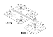
以下請參閱圖2A,顯示具有多數支座100例之一電子裝置的一安裝部份200的一立體圖。請注意,在某些實施例中,該安裝部份200可具有與所示者不同數目之支座100例,包括只具有一單一支座100例。請另外地參閱圖2B,顯示該安裝部份200例之一放大圖,其中以一分解狀態顯示該等多數支座100中之一支座。Please refer to FIG. 2A below, which shows a three-dimensional view of a
該安裝部份200可包括具有多數支座孔204之一板202。該板202可為一剛性或半剛性構件或面板。在某些實施例中,該板202可為附接該等多數支座100之一獨立組件。在其他實施例中,該板202可為一電子裝置之一體部件或組件,例如一框架、殼體、底盤、電路板或其一部份或多數部份。該等多數支座孔204可在該板上配置成由圖案208所示之一安裝圖案。類似地,該等多數支座100例亦可配置成該安裝圖案208使得該等多數支座100之各支座或其一托架102與該等多數支座孔204中之一支座孔對齊。在某些實施例中,該安裝圖案208可為適合使該等多數支座100對齊在一配件或裝置上之配合或互補安裝點或形貌體的任何圖案,且該安裝部份200及因此實施該安裝部份200之一電子裝置可附接或安裝在該配件或裝置上。在其他實施例中,該安裝圖案208可為一工業標準安裝圖案,例如視訊電子標準協會(VESA)安裝介面標準(MIS)。在另外實施例中,該安裝圖案208可為具有大約100mm×100mm、100mm×50mm、100mm×200mm、200mm×50mm之尺寸的一矩形配置或另一適當工業標準安裝圖案。The mounting
包括托架102之各支座100例可設置或附接在該板202之一底側上,且因此以虛線顯示。在其他實施例中,該托架102可為該板202之一體部件,或該板202之一部份可作為該托架102,且可由該支座100省略一分開或獨立托架102。該托架102可具有一柱孔(未圖示),且該柱孔可與該等多數支座孔204中之各支座孔對齊。該等多數支座孔204之各支座孔可為可插穿過該板202之厚度的一窗、缺口、開口或其他孔。因此,該等多數支座100之各支座的一柱104可插入該柱孔,且亦可插入該柱孔對齊之各支座孔204。Each
在某些實施例中,該等多數支座100之各支座的托架102可藉由多數鉚釘226附接在該板202上。在某些實施例中,該等鉚釘226可為該托架102之一部份且可插入板202中之互補孔,且在某些實施例中,該等鉚釘226可為該板202之一部份且可插入該托架102中之互補孔。與一互補孔接合後,各鉚釘可被壓平、被衝壓或變形以重疊該孔並將該托架102扣持在該板202上。In some embodiments, the
以下請參閱圖3A,顯示具有多數支座100例之一電子裝置300例的立體圖。在某些實施例中,該電子裝置300可為一運算裝置。在其他實施例中,該電子裝置300可為一桌上型個人電腦(PC)、一迷你桌上型PC、例如一繪圖卡之一外PC配件或擴充組件、或另一種運算裝置或組件。在其他實施例中,該電子裝置300可為需要安裝例如一路由器、數據機、機上盒、不斷電設備(UPS)或另一種電子裝置等的任一種電子裝置。Please refer to FIG. 3A below, which shows a three-dimensional view of an
該等多數支座100可在該電子裝置300之安裝部份306上配置成一安裝圖案。此外,該電子裝置300可具有一底盤304,且該底盤304具有一安裝側308。該安裝部份306可設置在該安裝側308上且在某些實施例中,可至少部分地設置或凹入該底盤304中。該底盤304亦可收容及支持該電子裝置300之其他組件,包括但不限於:電路板、處理器、記憶體、電源供應器、通訊埠、硬碟、電池及/或其他適當組件。該電子裝置300亦可具有可移除地附接或耦合在該底盤304上之一安裝蓋302。該底盤304可包括一安裝蓋凹部310,且該安裝蓋凹部310設置在該安裝部份306上以便將該安裝蓋302收納在該安裝蓋凹部310內。該安裝蓋302可附接在該電子裝置300上以便在不使用該安裝部份306及該等多數支座100時隱藏它們。換言之,當該等多數支座100之各支座在一未使用位置時(例如,請參見圖1A),它們可放置成與該安裝蓋凹部310齊平或在其下方使得該安裝蓋302可放置在該凹部內且與該底盤304之其他部份齊平或形成一平面。因此,當附接該安裝蓋302時,可保持該底盤及該電子裝置300整體之美觀及吸引力。The plurality of
請參閱圖3B,顯示該電子裝置300之立體圖,其中該安裝蓋302已移除,藉此暴露該等多數支座100,且各支座100之間隔件110已翻轉至圖1C所示之位置。在所示升高位置,該等多數支座100之各支座的間隔件110可延伸超出該底盤304且離開該安裝蓋凹部310。因此,各支座100此時被扣持在該升高位置且可在不使用一配接板之情形下與該底盤304外之一配件的一安裝點或組件接合。Please refer to FIG. 3B, which shows a perspective view of the
請另外地參閱圖3C,該電子裝置300係顯示為與一配件312接合。該配件312可為可能需要附接在該電子裝置300上之任何組件。例如,該配件312可為一壁安裝件、監視器安裝件、支架、桌安裝件、或其某些部份或托架。在其他實施例中,該配件312可為另一種組件或另一電子裝置。該配件312可使用一固結件314附接在各支座100之柱104上,且各固結件314可與各柱104之一固結孔(未圖示)接合或被該固結孔收納。請另外地參閱圖3D,該電子裝置300之多數支座100中之一支座的橫截面圖顯示為藉由一固結件314完全地接合或附接在一配件312上。該固結件314可將該配件312之一部份剛性地安裝在該間隔件110之一安裝表面上。因此,該配件312可藉由附接在該等支座100中之各或某些支座上而剛性地附接在該電子裝置300上。Please additionally refer to FIG. 3C, the
如上所述,當各支座100之間隔件110翻轉且設置在該升高位置時,各間隔件110可伸出該安裝蓋凹部310以便簡單地且容易地附接該配件312。如圖3D所示,因為該間隔件110之伸出,當附接在該電子裝置300上時,該配件312之一最低部份可與該底盤304之一表面,例如與托架102之一最上方表面分開距離316。因此,當將多數電子裝置附在一配件上時可不需使用一配接板。As described above, when the
100…支座
102…托架
104…柱
106, 112…第一部份
108, 114…第二部份
110…間隔件
200, 306…安裝部份
202…板
204…支座孔
208…(安裝)圖案
226…鉚釘
300…電子裝置
302…安裝蓋
304…底盤
308…安裝側
310…安裝蓋凹部
312…配件
314…固結件
316…距離
100...support
102...
圖1A至C係一支座例之立體圖;Figures 1A to C are three-dimensional views of an example of a seat;
圖2A至B係具有一支座例之一電子裝置的一安裝部份的立體圖;及Figures 2A to B are perspective views of an installation part of an electronic device with an example of a seat; and
圖3A至D係具有一支座例之一電子裝置例的立體圖。3A to D are perspective views of an example of an electronic device with a stand example.
100…支座
102…托架
104…柱
106, 112…第一部份
108, 114…第二部份
110…間隔件
312…配件
314…固結件
316…距離
100...support
102...
Claims (15)
Applications Claiming Priority (2)
| Application Number | Priority Date | Filing Date | Title |
|---|---|---|---|
| WOPCT/US18/51946 | 2018-09-20 | ||
| PCT/US2018/051946 WO2020060554A1 (en) | 2018-09-20 | 2018-09-20 | Standoffs with removable spacers |
Publications (2)
| Publication Number | Publication Date |
|---|---|
| TW202013124A TW202013124A (en) | 2020-04-01 |
| TWI698736B true TWI698736B (en) | 2020-07-11 |
Family
ID=69887796
Family Applications (1)
| Application Number | Title | Priority Date | Filing Date |
|---|---|---|---|
| TW108113416A TWI698736B (en) | 2018-09-20 | 2019-04-17 | Standoffs with removable spacers |
Country Status (3)
| Country | Link |
|---|---|
| US (1) | US11181954B2 (en) |
| TW (1) | TWI698736B (en) |
| WO (1) | WO2020060554A1 (en) |
Families Citing this family (3)
| Publication number | Priority date | Publication date | Assignee | Title |
|---|---|---|---|---|
| US11116101B2 (en) * | 2018-03-06 | 2021-09-07 | Hewlett-Packard Development Company, L.P. | Movable standoffs with posts |
| WO2021091547A1 (en) * | 2019-11-06 | 2021-05-14 | Hewlett-Packard Development Company, L.P. | Computing device stands and display mount interface spacers |
| CN114370563A (en) * | 2020-10-15 | 2022-04-19 | 华硕电脑股份有限公司 | Screen fixing device |
Citations (5)
| Publication number | Priority date | Publication date | Assignee | Title |
|---|---|---|---|---|
| US5881979A (en) * | 1997-06-04 | 1999-03-16 | Knoll, Inc. | Telescoping leveler |
| TW201305779A (en) * | 2011-07-26 | 2013-02-01 | Hon Hai Prec Ind Co Ltd | Connecting assembly and electronic apparatus having the same |
| US20130240688A1 (en) * | 2012-03-19 | 2013-09-19 | David Schwartz | Adjustable Foot for Furniture |
| CN204377298U (en) * | 2015-02-03 | 2015-06-03 | 广东美的暖通设备有限公司 | For household electrical appliance circuit board mounting structure and there are its household electrical appliance |
| CN204887744U (en) * | 2015-07-09 | 2015-12-16 | 浙江大华技术股份有限公司 | Cabinet |
Family Cites Families (7)
| Publication number | Priority date | Publication date | Assignee | Title |
|---|---|---|---|---|
| KR100526620B1 (en) | 1999-05-01 | 2005-11-08 | 삼성전자주식회사 | Structure For Fixing VESA Cover To L.C.D Monitor |
| JP4762005B2 (en) | 2006-03-01 | 2011-08-31 | 三洋電機株式会社 | Video display device |
| KR20080028235A (en) | 2006-09-26 | 2008-03-31 | 주식회사 대우일렉트로닉스 | Displayer comprising flat display mounting interface device |
| CN201349768Y (en) * | 2008-12-26 | 2009-11-25 | 科勒(中国)投资有限公司 | Supporting leg for being mounted on mounting bottom surface of furniture |
| US7856732B2 (en) | 2009-02-06 | 2010-12-28 | Omnimount Systems, Inc. | System for mounting an object to a surface |
| JP2010252213A (en) * | 2009-04-20 | 2010-11-04 | Funai Electric Co Ltd | Thin panel display device |
| RU2011145390A (en) * | 2011-11-08 | 2013-05-27 | Игорь Константинович Бирченко | FURNITURE SUPPORT |
-
2018
- 2018-09-20 US US17/048,679 patent/US11181954B2/en active Active
- 2018-09-20 WO PCT/US2018/051946 patent/WO2020060554A1/en active Application Filing
-
2019
- 2019-04-17 TW TW108113416A patent/TWI698736B/en not_active IP Right Cessation
Patent Citations (5)
| Publication number | Priority date | Publication date | Assignee | Title |
|---|---|---|---|---|
| US5881979A (en) * | 1997-06-04 | 1999-03-16 | Knoll, Inc. | Telescoping leveler |
| TW201305779A (en) * | 2011-07-26 | 2013-02-01 | Hon Hai Prec Ind Co Ltd | Connecting assembly and electronic apparatus having the same |
| US20130240688A1 (en) * | 2012-03-19 | 2013-09-19 | David Schwartz | Adjustable Foot for Furniture |
| CN204377298U (en) * | 2015-02-03 | 2015-06-03 | 广东美的暖通设备有限公司 | For household electrical appliance circuit board mounting structure and there are its household electrical appliance |
| CN204887744U (en) * | 2015-07-09 | 2015-12-16 | 浙江大华技术股份有限公司 | Cabinet |
Also Published As
| Publication number | Publication date |
|---|---|
| US20210255673A1 (en) | 2021-08-19 |
| US11181954B2 (en) | 2021-11-23 |
| WO2020060554A1 (en) | 2020-03-26 |
| TW202013124A (en) | 2020-04-01 |
Similar Documents
| Publication | Publication Date | Title |
|---|---|---|
| TWI698736B (en) | Standoffs with removable spacers | |
| US9578960B1 (en) | Supporting rack | |
| US11116101B2 (en) | Movable standoffs with posts | |
| TW201305779A (en) | Connecting assembly and electronic apparatus having the same | |
| US8254145B2 (en) | Electronic device with expansion card modules | |
| US20060087596A1 (en) | Display device | |
| US20140139998A1 (en) | Server rack | |
| JP2012195790A (en) | Television receiver and electronic apparatus | |
| CN101652042B (en) | Electronic apparatus | |
| JP6427868B2 (en) | Support device and table for portable information equipment | |
| JP2011249975A (en) | Electronic apparatus | |
| US8614889B2 (en) | Computer enclosure | |
| CN101930259A (en) | Monitor and computer | |
| US7522229B2 (en) | Flat panel display having support of multiple use states | |
| TWM602653U (en) | Quick release carrier | |
| JP4719928B2 (en) | Assembly of electronic device casing and support device, and set of this assembly and electronic device | |
| TWI510166B (en) | Fixing apparatus of expansion board | |
| CN213840086U (en) | Well accuse is dull and stereotyped and is used for dull and stereotyped mounting structure of well accuse | |
| US20210289652A1 (en) | Device mounts | |
| TW201422100A (en) | Electronic device and housing of electronic device | |
| CN210607929U (en) | Detachable concentrator | |
| JP6823278B1 (en) | Display device | |
| US20040057196A1 (en) | Integral computer | |
| US8605453B2 (en) | Electronic device with detachable printed circuit board | |
| JPH05108208A (en) | Expansion unit device |
Legal Events
| Date | Code | Title | Description |
|---|---|---|---|
| MM4A | Annulment or lapse of patent due to non-payment of fees |